

Page 1
@
<
Z
<
Z
0
<
SAFETY INSTRUCTIONS ............... 2
WARRANTY INFORMATION ............ 3
INTRODUCTION .................... 3
CONTROL DESCRIPTIONS ............. 4
CONNECTING SUBWOOFER ............ 5
TROUBLESHOOTING ................. 6
SPECIFICATIONS .................... 6
0
× > _ * >+>
[I||IMWII_
SM-LW12 1
8ERtnCE MANUAL
Page 2
i WARNING: TO REDUCE THE RISK OF FiRE OR ELECTRIC SHOCK, DO NOT EXPOSE THIS SPEAKER CABINET TO RAIN OR MOISTURE. ]
CAUTION k
RISK OF ELEC'IrRI €
SHOCK DO NOT OPEN
AVIS RlSCiUE DE CHOC IELEClrRI_tUE HE PAS OUVlUR
C.A_: TO RI_K3E n-lE RISK OF
I[1ECtlRIC5HOCK, IX) I_OT OF'F_. NO USER
SE_ PARTS INSIDE. REFI_ Sk'RVICS_
TO C3OALIFIED $_R_KI PERSON.
THIS SYMBOL INDICAI_ IHAT
D_OUS VOLTAGE COhlS111UI1NG
A RISK OF EUECIRIC5HOCK IS PRIESENT
WII141N IH1$ UNIT.
THI$ SYMBOL INDICAIE5 "IHAT THB_E
A.R£ IMPORTANT _
IINSIR_ IN "n_ELlllERA1LIRE
ACCOMPANYING THIESPEAK]ElL
SAFETY INSTRUCTIONS
Read Instructions - Readallsafety and operatinginstructionsbefore
operatingthe product.
Retain hlslruclfl.ons- Retainall safetyand operating instructions for
future reference.
Read Warnings- Readallwarnings on the product and in the
operatinginstructions.
Follow Instructions - Follow all operatingand use instructions.
Water and Moisture- Do not use the product nearwater; for
example,near abathtub, washbowl,kitchen sink, laundry tub, in a wet
basement, or near aswimming pool, etc.
Ventilation - Do not placethe product in a location or position that
interfereswith its proper ventilation. For example, do not setthe product
on a bed, sofa,rug, or similarsurfacethat may block the beat sink; or
placeit in a built-in situation, such as abookcase or cabinet that may
impede the flow of airaround the heat sink.
Placement - This product isdesignedfor floor placement only. Do not
place it on a cart or table. Do not place objectson top ofthe product, as
theywig vibrate off.
Heat- Placethe product awayfromheat sourcessuch as radiators,heat
registers,stoves, or other appliances(induding amplifiers)that produce
heat.
Power Sources - Connect the product only to a power receptacle
of the type described in the operating instructions or as marked on
product.
Grounding or Polarization - Do not defeat the product's grounding
or polarization feature.
Power Cord Protection- Routepower-supply cords so that they are
not likelyto be walked on orpinchedby items placed on or againstthem.
Pay particular attention to cords at plugs, convenience receptacles, and the
point where they exit fromthe product.
Cleaning- Clean theproductonly with a drydoth; do not use any
liquids such as water orsolvents.
Power lanes - Locate an outdoor antenna away from power lines.
Non-Use Periods- Unplug the product's powercord fromthe oudet
when left unused for along periodof time.
Object and Liquid Entry - This apparatus shall not be exposed to
dripping or splashng and that no objects filled with liquids, such as vases,
shall be placed on the apparatus. Do not use the product near water; e.g.,
near a bathtub, washbowl, kitchen sink, laundry tub, in a wet basement,
or near a swimming pool, etc. Use care so that objects do not fall, and
liquids are not spilled into the enclosure through openings.
Damage Requiring Service- If the product requiresservice,use only
qualified servicepersonnel when:
A. The power supply cord or the plug hasbeen damaged; or
B. Objects have fallen,or liquid hasbeen spilled into the product; or
C. The product has been exposedto rain; or
D. The product does not appear to operatenormally, or exhibits a
marked change in performance;,or
E. The product hasbeen dropped, or the endosure damaged; or
F. Fuse blows repeatedly.
Servicing - Do not attempt to servicethe product beyond what is
describedin the operatinginstructions.All otherservicingshould be
referred to qualified servicepersonnel.
In the event your Cerwin-VegaSubwoofer failsto operateproperly, please
contactthe dealerwhere you purchased the unit. Or, for further
assistancecontact us atthe addsemeslisted below.
The HT and LW powered subwoofers are CE compliant.
CERWIN-VEGA, 555 EAST EASY STREEr, SIMI VALLEY, CA 93065 TEL:+l-805-584 9332 FtOe+1-805 583-0865 • WWW.CERVa_-Vm&CO._
Cr_w_-VEcat CANt_A, 1655 FEtDSVt_Or. #2, PlOddiNG, Om'tauo LIW 3R7 • C_WIN-VECatEUROVt,Dt,u Au_ 1, DK-9610 NO_G_, D_Mm, K
2
Page 3

CERWIN-VEGA'S LIMITED WARRANTY
WELCOMETOTHEFAMILY[
Firstoff,youhavegreattasteinloudspeakers.AtCerwin-Vega,deepbass
and greathighsareawayof life. Niceto knowthereareafewpeopleout
therewhoshareourpassionformusic.You'llbegladtoknowthatthisis
afamily-ownedcompany(hasbeensince1953). Andweconsideryouto
bethe newestmemberofthe family.
Webopeyourspeakersgiveyouyearsofenjoyment.Ofcourse,in theevent
ofa problem,makesureyoufamiliarizeyoursdfwiththiswarranty.Welike
to thinkthatwhileyou'resittinginfrontofyourspeakers,we'restanding
behindthem.Andnowa fewchoicewordsfromourlawyer.(Hey,every
familyhasone.)
WHO'S COVERED BY THIS WARRANTY?
Cerwin-Vega's Limited Warranty onresidential speakersextends only to
the original purchaser asevidenced by the original BillofSaleand only to
the residentialspeakers purchased from authorizedCerwin-Vega dealers.
Ten words of advice:Retain the originalbillof salein asad placet
WHAT'S COVEREDBY THIS WARRANTY?
C.e_vin-Vegawarrants that allnew residential speakers shall be flee from
defectsin material and workmanship, under normal and proper use.
Cetwin-Vega agreesto repair orreplace(at ouroption) allsuch defective
parts at no charge for labor or materials.
WNM'S NOT COVEREDBY THIS WARRANTY?
This Limited Warranty does not apply to defective equipment that: has
been altered orrepairedby other than factory approvedprocedures; has
been subjected to negligence, misuse or accident;has been damaged by
improper line voltage; had its serialnumber orany part of it altered,
defaced, orremoved; has been used for otherthan home entertainment
purposes; or has been used in awaythat is contrary to Cerwin-Vega's
written instructions.
Except as provided by statute, this Limited Warranty does not cover
losses,consequential or otherwise, resulting from the improper use of, or
inability to operate, any Cerwm-Vega product.
HOW LONGDOESTHEWARRANTYEXTEND?
Cerwin-Vega'sLimitedWarrantyextendsforaperiodoffive(5) yearsfor
allsystemspeakercomponentsandtwo(2)yearsforallassociated
electronicscomponents,includingamplifierand controllerdevices,'from
dateofpurchaseasshownonthe originalBillofSale. Ifa defectexists
withinthewarrantyperiod,thewarrantywiltnot expireuntilthedefect
hasbeenfixed.
The warranty period willalso beextendedif the warranty repairshave
not beenperformed due to delayscausedby drcumstancesbeyond the
control of the originalpurchaser,or ifthe warrantyrepairsdid not
remedy the defect and the original purchaser notifies Cerwin-Vegaor the
originaldealeroran AuthorizedCerwin-VegaService Centerof the
failure of the repairswithin 30 days afterthey were completed.
HowDOYOUGET WARRANTY SERVICE?
Inorder to obtainwarrantyservice,contact youroriginaldealer or
distributor,or an AuthorizedCerwin-VegaServiceCenter. If,for some
reason, you havetrouble locatinga servicerepresentative,contact Cerwin-
Vega'sCustomerService Department forassistance:
Cerwin-Vega!
Customer ServiceDept.
555 EastEasy Srteet
Simi Valley, CA 93065
PHONE: 805-584-5300 or FAX:805-526-3653
In some cases, the Customer ServiceDepartment can solvea service
problem without anyreturn of equipment, thereby avoiding transit delays.
WHATIF THEPRODUCTMUSTBERETURNED?
Iftbe CustomerServiceDepartmentdeterminesthattheequipmentmust
hereturnedtoCerwin-Vegaforservice,a ReturnAuthorizationwillbe
issuedbymail,and thedefectivemerchandisemaybeshippeddirectlyto
theaboveaddressfreightprepaid,alongwithacopyofboththe Return
Authorizationand theoriginalBillofSale.
The product will be replaced orrepaired (atour option)and returned to
the originalpurchaser. Only the return postagewill be paid byCerwin-
Vega. Cerwin-Vega will not be responsible for damage occurringin
shipment from the originalpurchaser or dueto improper packing
materials. Rememberto pack all equipment carefullyandin the original
carton ifpossible. Additional chargesmay be added if new packing
materials arerequired for return shipment. SAVEYOUR ORIGINAL
PACKING MATERIALS_
WHM ARE OTHERREMEDIES UNDERTHE LAW?
The exerciseof any of the provisions under the Limited Warranty does
not affectthe protections or remedies of the originalpurchaser under
otherlaws. lfyou have additionalquestions aboutservice,write or callthe
Customer Service Department. This Limited Warranty appliesto all
residential speakers, andsupersedesallpreVmuswarrantystatements.
Cerwin-Vega reservesthe right to make changesin product design and
specificationsat any time.
EXCEPT AS PROVIDED HEREIN AND BYAPPLICABLE LAW,
CERWIN-VEGA MAKESNO ADDITIONAL REPRESENTATION
OR WARRANTY OF ANY NATURE WHATSOEVER, EXPRESSED
OR IMPLIED, AS TO THE EQUIPMENT, INCLUDING BUT
NOT LIMITED TO, THE MERCHANTABILITY,FITNESS FOR A
PARTICULAR PURPOSE, DESIGN CONDITION OR
WORKMANSHIP OF THE EQUIPMENT, OR THE QUALITY OF
THE MATERIALINCLUDED THEREIN, THIS LIMITED
WARRANTY CONSTITUTES THE SOLE AND ENTIRE
AGREEMENT BETWEEN CERWIN-VEGA AND THE ORIGINAL
PURCHASER.
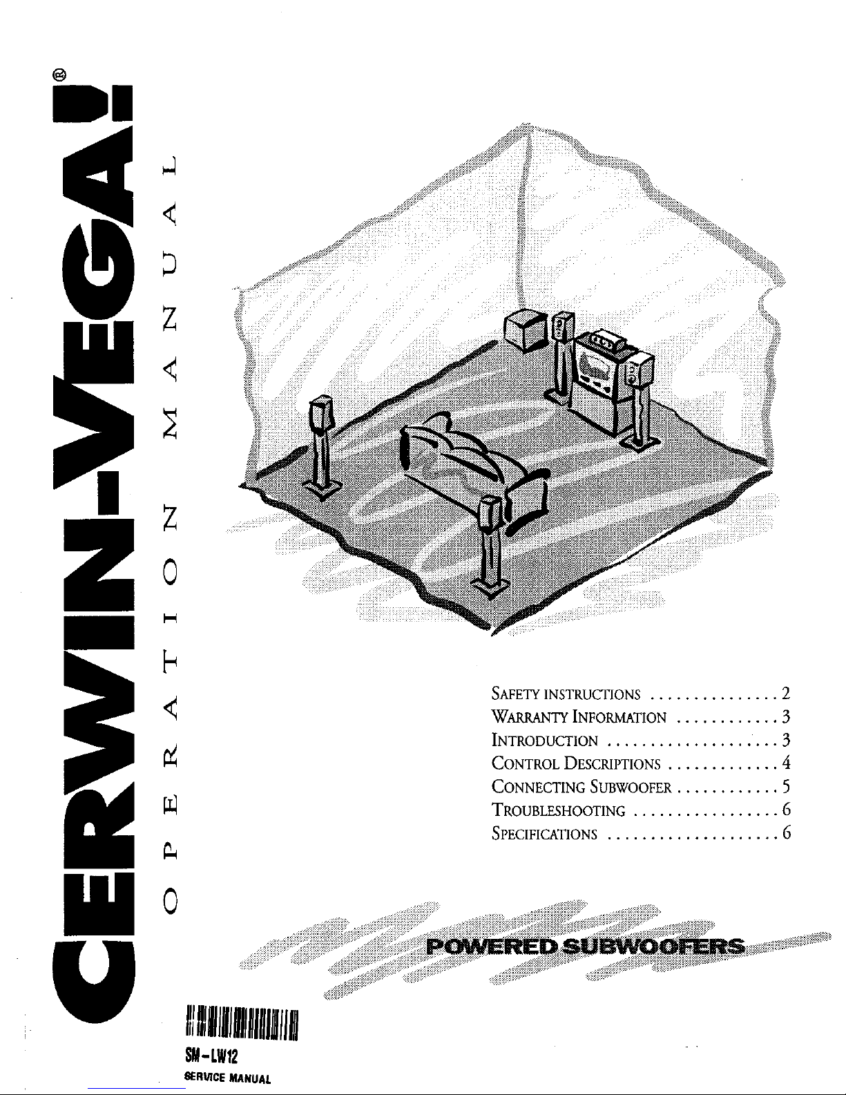
INTRODUCTION
This manual coversoperationinformationfor allPowered Subwoofers in
Cerwin-Vega'sHT-Sand LW series. Illustrations of control locationsand
book-up wiring may differ in physical appearance and location than those
shown on the actualproduct you own. However, the operation
information isstill the same.
PRIOR TO INSTALLATION
Carefully unpack your subwoofer, saving the box and packing materials
incaseyou ever need to transport,ship,or move your subwoofer. Before
continuing with installation, pleasemake sure the subwooferisunplugged
and the power switch is turned OFF.
sd,xtul _ Sct_kageukctlonuoltcb® totheproperACvoltage,
ver# prot_ f_e rat=g(O_ and value)® b(ore aue_ang toconnea
d,ifud,wooferwAC_wer.
INSTALLATION
Pleasereadthe remaining pagesto determine which installation
procedure is best for your audiovideo system. For additionalhook-up
connections, you maywant to referto yourAN receiver,processor,or
amplifier's manual. NOTE.. Besureto readand obsen_ the"Safety
Insmuffons" (wepage2) be_re startingthe installation.
Page 4

CONTROL DESCRIPTIONS
ATTENTION! Each subwoofi.r has speaker-level and _e-levd input
connections¢choose only one optionfor hook-up. DO NOT USE
BOTH INPUT CONNECTIONS AT THE SAME TIME!
The following (numbered) comrols are located on the subwoofer's rear
panel, as shown in Figures 1 and 2.
(!) LINE-LEVEL INPUT: Stereo line-level inputs to subwoofer. Use
these RCA jacks to connect audio signals from line-level outputs from
an AN receiver/preamp/processor. (seefigure 3 & 4,j_r hook-up)
(_) SPEAKER-LEVEL INPUT: Stereo speaker-levelinputs to
subwoofer. Use these terminalswhen line-levelconnections are not
availablefrom A/V receiver/preamp/processor.
(seefigure 5,fir hook-up)
(_) VOLUME CONTROL: Controls volume levelofsubwoofer. Use
to balance the outputof the subwoofer with the main speaker output.
@ CROSSOVER FREQUENCY: The crossovercontrol allows you m
adjust the upper limit of the subwoofer's frequency response from 40
to 120Hz. The subwoofer's response will begin rolling offabove the
set frequency. Set the CROSSOVER FREQUENCY to the lower
value listed in the main speaker manual.
(_) SPEAKER-LEVEL OUTPUT: Audio loop of stereohigh-level
(SPEAKER-LEVEL)inputs. Use m loop (continue) signalto speaker
connections to the leftandright main speakers.
(seeflgure 5,for hook-up)
_) LINE-LEVEL OlYl'PUT (LW-10/12*, HT-S10MI2A): Useto loop
the full-rangeline-levdsignalback to the receiver/preamplifier/amplifier
fordistribution to mainspeakers. Referto the owner's manual provided
with yourreceiver/preamplifier/amplifier.(seefigure4,fbr hook-up)
0 LINE-LEVELOUTPUT (HT-SI5A & LW-15*): Use to loop
signal back to the recdver/preamplifiedamplif]erfordistribution to the
main speakers. Use the Line-Levd Output ifyou wish to filter low
frequenciesoutof the signalgoing to your main speakers. Referto the
owner'smanual providedwith your receiver/preamplifier/ampl_er.
(seefigure3, j_r hook-up)
®
®
@
®
@
@
PHASE: Compensates for havingsubwoofer and main speakers in
different locations. Ideally,subwoofer sound should reach the
listening position at the same time assound from the main speakers.
However, if the distance from the listening position to the
subwoofer, and from the listening position to the main speakers
differ, the sound from each willreach your earsat different times.
The PHASE control delays the signal 180 degrees,so the subwoofer
output will blend with that oftbe main speakers. Slide the PHASE
switch to "180." At the listening position, listen to the midbass
output. If it sounds weak,set PHASE back to "0."
POWER LED: Power indicatorlamp. Glows green in "AUTO
ON" mode if audio signalispresent. Glowsred in both "OFF" and
"AUTO ON "modes if receivingAC power, and audio signalisnot
present afterapproximately20 minutes.
POWF_: Two-position power switch. In the "AUTO ON" mode,
the subwoofer's amplifierisautomaticallyactivated if an audio signal
is present and willautomaticallybecome inactivewhen there is no
audio signalpresent afterapproximately20 minutes. In the "OFF"
mode, power isshut offto the amplifier.
VOLTAGE SELECTION (LW-X Models only) : User-switchable
voltageselectionforuse with 115 or 230 volt AC. Auentiom A//
suhomofermndds comefrom thefactorypreset to 115 volts. To select
adifferent voltage,usea flat-headscrewdriverto reposition the switch
to the desiredvoltage. WARNING: Severedamagemay mult from
improperlysekcted voltage.Make sw_ you know the voltage
requirement of tl_ _untry you are in beforeattempting to connect
this mhomofer toACpower. Obwrveproper fuse rating (typeand
value)@for sde_cd voltage®.
POWER CORD RECEPTACLE: Connect IEC cord to this
receptacle. If the cord supplied doesnot fit artavailableAC outlet,
purchase the correctAC cord from your audio dealeror an electrical
supply store.
REPLACEABLE FUSE: Protectssystem from overload,replace
with fuserating as indicated on amplifier panel at fuse location.
o o
@
O
?
&
o@ ® o ® o
Figure1. Connectionpandj_rthe HT-S15AandLW-15/15X.
Figure2 ConnectionpandfortheHT-SlOA, HT-S12A, LW-lO/lOX
andLW-12/12X
4 * Designates LW or LW-X model.
Page 5

PLACEMENT
Cerwin-Vega SubwooferSystemscan be positioned anywhere on the
room's floor. For best performance however, placethe subwoofer nearthe
same wallas your mainspeakers.Experimentto find the areaofoptimum
performance.
NOTE" Usuallythe subwooferwillsound louderwben it'splaced next toa
wallorin a comer.
A 7TENTION! Do notplace the subwoofertoo closeto your television.
Some televisions are especially sensitive to the magnetl: field produced
by the subwoofer. If your television produces distorted colors a)qer
installation, this can be corrected bymoving the subwooferfurther
awayfrom the television until normal coloris returnea_
CA UTION! Cerwln- Vega Sulnooofers are intended for floor
placementonly!Do notplaceheavy objects of any type, (such as a
television) on top of a Cerwin-Vega Subwoofer!
CONNECTING YOUR SUBWOOFER
LINE-LEVEL CONNECTIONS
SUBWOOFER CONNECTION PANEL UNE4._VEL CONNECTIONS
I
_ I_OM UNE4.EVEL
! {may roquife am Rt:A "y" adapter
! i '..... R_,,u, Or,T)
,.......... i
Une-Level Connections for Ifte HT-S I SA and LW* 15/15X
SUBWOOFER CONNECTION PANEL UNE,Lk'VELCONNECTIONS
o...............................o I.
/ - - ,:. i io_.,,J_
_ UN E4.EVEL OUT
(_y r_eir# inn RGA -?" a_i_
for m_** _u#¢et like SUB _)
I
IAne-14_ei Connections foe' the h'T-S 10A, HT-$ t _. LW-IO/IOX
and LW-12/t_,
Figure3. Figure4.
Figure3&4. C_nnectingL_ and right line_leve__u_uts _f a_ A/V receivert_k_ and right llne_levdinputs _fthe Cerwin-Vegasubw_fer. Rememberto
maintain leftto L°ft,right to right,connectiom!Rememberto maintain left to left,right to t_ght,(+) to (+)and (-) to (-)connections.
SPEAKER-LEVEL CONNECTIONS
SUBWOOFER CONNECTION PANEL FROM SPEAKER-LEVEL OUT
_re 5. Connectleft and right.,_ker-_. outputsofa,, A/V receiverto leftand rightspeaker-levelinputsof thesubwoofe_.ThenconnectL_ and rightspeaker-
ou_utt of t_. mbwoofrr, with the mam lrJ_and rightsp_akosofyour qsten_ Remembertomamtamle_tole_,right to right,(+)te (+)and
(4te(-)conm_o_u.
Page 6

TROUBLESHOOTING
SYMPTOMS
Basssounds distorted
CAUSES SOLUTIONS
Subwoofer amplifier is at maximum output Lower subwoofer volume or receiverlevelcontrol
Receiver tone controls are set too high Set bass flat;usetone controls sparingly
Distortion with volume control near minimum Defective receiveror preamplifier, or shorted Repair defectivereceiver, preamplifier or replace
speaker wires speakerwires
Distortion on music peaks or sound effects Dynamic soundtrack (e.g., explosions) Turn down volume control to lower over£1
range; use a more powerfialreceiver/amplifier
Buzz, hum, or crackle when connecting wires Connecting wires with power on causes tramient Connect wires only when system power is off
signal spikes
50160 cyclehum when systemis on Residentialgrounding problem Use a three-to-two prong AC adaptor (available
at your audio dealer or localelectronic supply).
No sound after listening at high levels Amplifier's thermal protection has been Lowersubwoofer volume and allow amplifier to
temporarily activated cool down; sound should resume automatically
Volume control is at maximum, yet sound is low Both channels are not being driven Use an RCA "y" adapter[o drive both channels
SPECIFICATIONS: HT-S SERIES SPECIFICATIONS: LW SERIES
HT-S10A LW-10/10X
F_QUENO/RESFONSE: 30 to 150 Hz F_EQUENO/RESPONSE: 32 Hz to 180 Hz
A_puF[ra Po'm_ Otm,i_: 100 Waas (RMS) _uHr_ PowL_OLrrP_: 100Wat,s(RMS)
c.o_2_.............. c2_n£"."°__t"Z92"9ogAO_2_50_EL_28__dB_2_"_.....
PotaarrY SWffCH: 0° m 180"(userseLectabLe)
St_SONICFILTE_ 18dB per octavebelow30 Hz
VOLTAGe: 115Vac
DtMF_I$1ONS(H XW x D): 1T' x 15" x 15"/ 432 can• 38.1cm x 38.1 cm
Po_r'r SWITCH: 0°or 180° (t_er sHeo_ble)
.........................................
s_E"2cF'J___........ 18'iB_y"= _°w3!___L.....................
VOLT/*_E: 115Vac (LW-10), 115/230 Vac (LW-10X)
DIMF_ZSlOi'lS(H XW XD): 18.5" x 12"x 18.75" / 47 canx30.5 cm x40 cm
o._^____w?,_Em-...... _E__(z_5_.o_....................... _y____5.q__y__,5__-........ 85*_(23.0_.............................................
FINISH; Blackwoodgralnvinyl FINISH: Black woodgrainvinyl
HT-S12A LW-12/12X
F_QUENCYR_PONSF_ 28 m 150 Hz FF,£qUE_ P,_OI_S_: 30 Hz _o150Hz
A_FI_. POW_ OU'I_sr: 150Wa_ (RMS) _FI_ Po'm.a O_: 150 Warn (RMS)
D_t_. D_sl¢;n: 12" high _iclmcy ,_,eofer/diexas__¢odnum flame DRIVERD_SmN: 12" high ei_ciene/weof_ldieost aluminumframe
C_OSSOW_.: Confiauomly variableflora 40 to 150 Hi @ 18 dBlocrave Ceosso'€_: Contin_i_sly variablefrom40 -150 Hz @18dB/octav:
POL_'_ Swrrol: 0°oe 1800 (l_e_wi:oable)
SUBSONICFILTE_ 18dB pe_o_taw bdow 28 Hz
VOLT^G_ 113Vac
DIM_e_SlONS(HXW XD): 19" x 17"x 17" 1483 _ x43.2 _m x432. o_
U_pAO_D WO_Wr: 60 _b(27.3 k0
F*_rSH: Bl,_kwo_.-..i, _.orl
pO_l_r_ SWITOt: 0_ or 180" (users_able)
SUBSONICFILTT2.: 18dB per octavebelow 30 Hz
VOLTAGE: 115 Vac (LW-12), 115/230 Vac(LW-12X)
DI_a',ZSIO_S(H x W x D): 19.5" x 14"x 17.3" / 49.5 cmx 35.6 cmx 44 nB
UNe^C_[_ WEm_: 60 Ib(27.3 kg)
FINISH: Bhck v,oodgr,ln vin_l
HT-S15A LW-15/15X
FREQUENCYRESPONSE: 25 to 150 Hz Fp_qUENC_IL_eo_s_ 27Hz to 150 Hz
AMmFIERPOWEaOL_PUT: 200 Watts (RMS) A_pu_ Pow_. O_: 200 Wa_ (RMS)
DRrVERDESIGN: 15" high dF_Aenc/_ferl_lie_st duminum flame De.lv_ DESIGN: 15"h_h *:_deBq, w_of_/ditcas_ aluminum frame
Crossov_.: Condmmusly _aiable from40 to 150Hz @ 18dBIoctave Cgossov_: Continuously variablefrom40 -150 Hz @18dB/oc_ave
POLARITYSWiTOA: 0_or 180_ (m_"sd_.'oable} PoLg_.ffYS_O4: 0"ot 180"(m_zs_le)
SU_ONICFILTE_ 18dB per octavebdow25 Hz SlaVONICFILTEg: 18 dBperochre below25 Hz
VOLTAGE: 115Vac VOLTAGE; 115Vac (LW-I8). 1151230Va_ (LW-I 5X)
DIM_ASlONS(H XWXD): 23.5" x 18.75" x 18.75" / 59.7 _ x 47.6 _ra x 47.6 cm Dit,_t_sloNs (H XWx D): 21"x IT x 18" 1533 o_ax 43.2 _ x 45.7 can
UNpt_ED WElkin': 72 Ib (32.8 Do) UNPt_g_ WEtGFrr: 72 Ib(32.8 kg)
FINISH: Bleakv,_d_n vinyl FINISH: Blackwoo_r_ _iny[
Geawln-V_ismmtanfl,/mMngtomlm_a tbehlgbe__ sland=ads.Asan:s_ltolrtheseeffom,raoclificath_roayh_madefrmntimetotimeto_tistiag_a_ _t _r _.
6 Spedfica_m andappearar.emaydiff=fromthoseIlatedor#aowain thismaaual.
 Loading...