

Page 1

CVM-1224FXUSB
CVM-1624FXUSB
PROFESSIONAL AUDIO MIXER (p. 2)
TABLE DE MIXAGE AUDIO PROFESSIONNELLE (p. 30)
MESA DE MEZCLAS PROFESIONAL (p. 58)
PROFESSIONELLEN AUDIO-MIXER (S. 86)
Page 2
IMPORTANT SAFETY INSTRUCTIONS
CAUTION: THE LIGHTNING FLASH WITH AN ARROWHEAD SYMBOL WITHIN AN EQUILATERAL TRIANGLE IS INTENDED TO ALERT
THE USER TO THE PRESENCE OF UN-INSULATED DANGEROUS VOLTAGE WITHIN THE UNITS ENCLOSURE THAT MAY BE OF
SUFFICIENT MAGNITUDE TO CONSTITUTE A RISK OF ELECTRIC SHOCK TO PERSONS.
WARNING: THE EXCLAMATION POINT WITHIN AN EQUILATERAL TRIANGLE IS INTENDED TO ALERT THE USER TO THE PRESENCE
OF IMPORTANT OPERATING AND MAINTENANCE (SERVICING) INSTRUCTIONS IN THE LITERATURE ACCOMPANYING THE
PRODUCT.
NOTE: THE HAND WITHIN AN EQUILATERAL TRIANGLE IS INTENDED TO ALERT THE USER TO SPECIFIC GUIDANCE AND
INFORMATION REGARDING THE OPERATION OF THE UNIT, AND SHOULD BE READ FULLY BEFORE USING THE UNIT FOR THE
FIRST TIME.
CAUTION: TO REDUCE THE RISKS OF FIRE OR ELECTRIC SHOCK DO NOT REMOVE ANY COVERS, OR OPEN THE UNIT. THERE ARE
NO USER-SERVICABLE PARTS INSIDE. ALL SERVICING SHOULD BE REFERRED TO QUALIFIED SERVICE ENGINEERS.
WARNING: READ AND FOLLOW ALL THE SAFETY AND OPERATING INSTRUCTIONS BEFORE CONNECTING OR USING THIS UNIT.
RETAIN THIS USER MANUAL FOR FUTURE REFERENCE. ALL WARNINGS ON THE UNIT AND ITS PACKAGING SHOULD BE READ AND
FOLLOWED.
WARNING: This product contains a chemical known to the State of California to cause cancer and birth defects or other
reproductive harm.
CAUTION: To reduce the risks of fire or electric shock do not expose this product to rain or moisture. Do not use this product
near water; for example, near a bath tub, washbowl, kitchen sink, laundry tub, in a wet basement or near a swimming pool.
Unplug the unit from the wall outlet before cleaning. Never use thinner, cleaning fluids, solvents or chemically impregnated
cloths. For cleaning always use a soft dry cloth. Unplug this product during lightning storms or when unused for long periods of
time.
CAUTION: The unit should be installed so that its location or position does not interfere with its proper ventilation. For example,
it should not be situated on a bed, sofa, rug or similar surface that may block the ventilation openings; or placed in a buil t-in
installation, such as a bookcase or cabinet, that may impede the flow of air through its ventilation openings. The unit should be
situated from heat sources such as radiators, heat registers, stoves or other devices (including amplifiers) that produce heat. No
naked flame sources, such as lighted candles, should be placed on, or near the unit.
WARNING: Do not place this unit on an unstable surface, cart, stand or tripod, bracket or table. The unit may fall, causing
serious injury to a child or adult and serious damage to the unit. Use only with a cart, stand, tripod, bracket or table
recommended by the manufacturer or sold with the unit. Any mounting of the device on a wall or ceiling should follow the
manufacturer’s instructions and should use a mounting accessory recommended by the manufacturer. An appliance and cart
combination should be moved with care. Quick stops, excessive force and uneven surfaces may cause the appliance and cart
combination to overturn. Use only with the cart, stand, tripod, bracket, or table specified by the manufacturer, or sold with the
apparatus. When a cart is used, use caution when moving the cart/apparatus combination to avoid injury from tip-over.
NOTE: Should the unit become damaged beyond repair, or reaches the end of its life, please consult the regulations regarding
disposal of electronic products in your region.
NOTE: Cerwin-Vega cannot be held responsible for damage, and, or including data loss caused by improper use of the unit and
or the applications provided for use with the unit.
2
Page 3

IMPORTANT SAFETY INSTRUCTIONS
CAUTION TO PREVENT ELECTRIC SHOCK, MATCH WIDE BLADE OF PLUG TO WIDE SLOT FULLY INSERT.
ENGLISH: The apparatus shall be connected to a Mains socket outlet with a protective earthing connection.
GERMAN: Das Gerät ist eine Wandsteckdose mit einem Erdungsleiter angeschlossen werden.
FRENCH: L’appareil doit être connecté à une prise secteur avec connexion à la terre.
SPANISH: El aparato estará conectado a una toma de red eléctrica con una conexión a tierra.
ITALIAN: L’apparecchio deve essere collegato a una presa di rete con una connessione a terra protettiva.
1. The unit and power supply should only be connected to a power supply outlet only of the voltage and frequency marked on
its casing.
2. Protect the power cable from being walked on or pinched particularly at plugs, convenience receptacles, and the point where
they exit from the apparatus.
3. Do not defeat the safety purpose of the polarized or grounding-type plug. A polarized plug has two blades with one wider
than the other. A grounding type plug has two blades and a third grounding prong.
The wide blade or the third prong is provided for your safety. If the provided plug does not fit into your outlet, consult a
qualified electrician for replacement of the obsolete outlet.
4. If the mains plug supplying this product incorporates a fuse then it should only be replaced with a fuse of identical or lower
rupture value.
5. Never use a damaged or frayed power cable; this can introduce serious risk of exposing lethal voltages.
6. The power supply cable of the unit should be unplugged from the wall outlet when it is to be unused for a long period of time.
7. Only use attachments/accessories specified by the manufacturer.
DO NOT ATTEMPT SERVICING OF THIS UNIT YOURSELF. REFER SERVICING TO QUALIFIED SERVICE PERSONNEL.
Upon completion of any servicing or repairs, request the assurance that only Factory Authorized Replacement Parts with the
same characteristics as the original parts have been used, and that the routine safety checks have been performed to guarantee
that the equipment is in safe operating condition.
REPLACEMENT WITH UNAUTHORIZED PARTS MAY RESULT IN FIRE, ELECTRIC SHOCK OR OTHER HAZARDS.
ATTENTION POUR …VITER LES CHOC ELECTRIQUES, INTRODUIRE LA LAME LA PLUS LARGE DE LA FICHE DANS LA BORNE
CORRESPONDANTE DE LA PRISE ET POUSSER JUSQUíAU FOND.
This unit should be serviced by qualified service personnel when:
The power cord or the plug has been damaged
Objects have fallen, or liquid has been spilled into the unit
The unit has been exposed to rain or liquids of any kind
The unit does not appear to operate normally or exhibits a marked change in performance
The device has been dropped or the enclosure damaged.
3
Page 4

REGULATORY CERTIFICATION
Cerwin-Vega declares under our sole responsibility that this product, to which this declaration relates, is in conformity with the
following standards:
The Declarations of Conformity can be obtained from Gibson Europe BV - Kamerlingh Onnesweg, 2 - 4131 PK Vianen - The
Netherlands Tel : +31 347 32 40 10 - Fax : +31 347 32 40 15
This device complies with Part 15 of the FCC Rules. Operation is subject to the following two conditions: (1) this device may not
cause harmful interference, and (2) this device must accept any interference received, including interference that may cause
undesired operation.
Warning: Changes or modifications to this unit not expressly approved by the party responsible for compliance could void the user's
authority to operate the equipment.
NOTE: This equipment has been tested and found to comply with the limits for a Class B digital device, pursuant to Part 15 of the FCC
Rules.
These limits are designed to provide reasonable protection against harmful interference in a residential installation. This equipment
generates, uses, and can radiate radio frequency energy and, if not installed and used in accordance with the instructions, may cause
harmful interference to radio communications. However, there is no guarantee that interference will not occur in a particular
installation. If this equipment does cause harmful interference to radio or television reception, which can be determined by turning
the equipment off and on, the user is encouraged to try to correct the interference by one or more of the following measures:
– Reorient or relocate the receiving antenna.
– Increase the separation between the equipment and receiver.
– Connect the equipment into an outlet on a circuit different from that to which the receiver is connected.
– Consult the dealer or an experienced radio TV technician for help.
This Class B digital apparatus complies with Canadian ICES-003.
4
Page 5

INTRODUCTION
UNPACKING & INSTALLATION
FEATURES
Thank you for your decision to purchase Cerwin-Vega’s new CV Mixer Series professional audio mixer! Engineered for
superior sound reproduction, the CV Mixer Series line of professional audio mixers deliver top quality audio at an
affordable price. The CV Mixer Series offer a standard of reliability and efficiency that makes them the perfect solution
for every DJ, musician, and sound engineer. Welcome to a new level of professional quality sound performance!
Although it is neither complicated to install, nor difficult to operate your new mixer, a few minutes of your time are
required to read this manual for a properly wired installation, and to become familiar with the unit’s features. Please
take great care in unpacking the unit and do not discard the carton and other packing materials. They may be needed
when moving the unit and are required if it ever becomes necessary to return the unit for service. Never place the unit
near a radiator, in front of heating vents, in direct sunlight, in excessive humidity, or dusty locations to avoid damages
and to guaranty a long reliable use. Connect the unit with the system components according to the description on the
following pages.
• 4 Mono and 4 Stereo line input with 6 XLR microphone inputs (12-Channel CVM-1224FXUSB)
• 8 Mono and 4 Stereo line input with 10 XLR microphone inputs (16-Channel CVM-1624FXUSB)
• Main L/R ¼” jack and XLR output and ALT 3/4 ¼” jack output
• 3-Band channel equalizer designed for ±15 dB (HF, LF) and ±12 dB (MF) control on input channel
• Phantom power (+48V) switch for easy connection of condenser microphones that typically require an external
power supply
• Detachable rack ears for mounting in a standard 19” rack enclosure
• Peak LED indicator to check on the signal input of each microphone channel
• Gain (trim) level control with sensitivity markings for both microphone and line inputs
• Low Cut (HPF) switch toggles the filter, with a cut-off frequency at 75Hz, to eliminate background microphone
rumble
• Pre/Post switch to set the aux signal as pre- or post-fader for foldback/monitoring mix or to preserve the
wet-to-dry ratio on aux sends
• Aux and EFX controls to adjust the level of the signal sent to the respective bus
• Pan control (mono channel) to position the signal across the master left and right bus
• Balance control (stereo channel) to adjust the level between left and right signals
• PFL (pre-fade listen) switch with adjacent indicator to allow the mixer to listen to each channel before it reaches
the main mix
• Built-in Vega-effects 24-bit digital signal processor with 100 selectable programs including reverb, echo, chorus
and flange
• Vega-effects master or footswitch on/off control
• USB input and output for laptop computer playback and recording
• Tape in stereo RCA jacks for connection to a CD or MP3 player
• Record out stereo RCA jacks for connection to a audio recorder
• Individual channel and main level control using 60mm faders
• Level control for headphone and control room connections
5
Page 6
FRONT PANEL CONTROLS – CHANNEL CONTROL SECTION
CONTROL
MAX.
BOOST/CUT
FREQUENCY
TYPE
HIGH
±15dB
12kHz
Shelving
MID
±12dB
2.5kHz
Peaking
LOW
±15dB
80Hz
Shelving
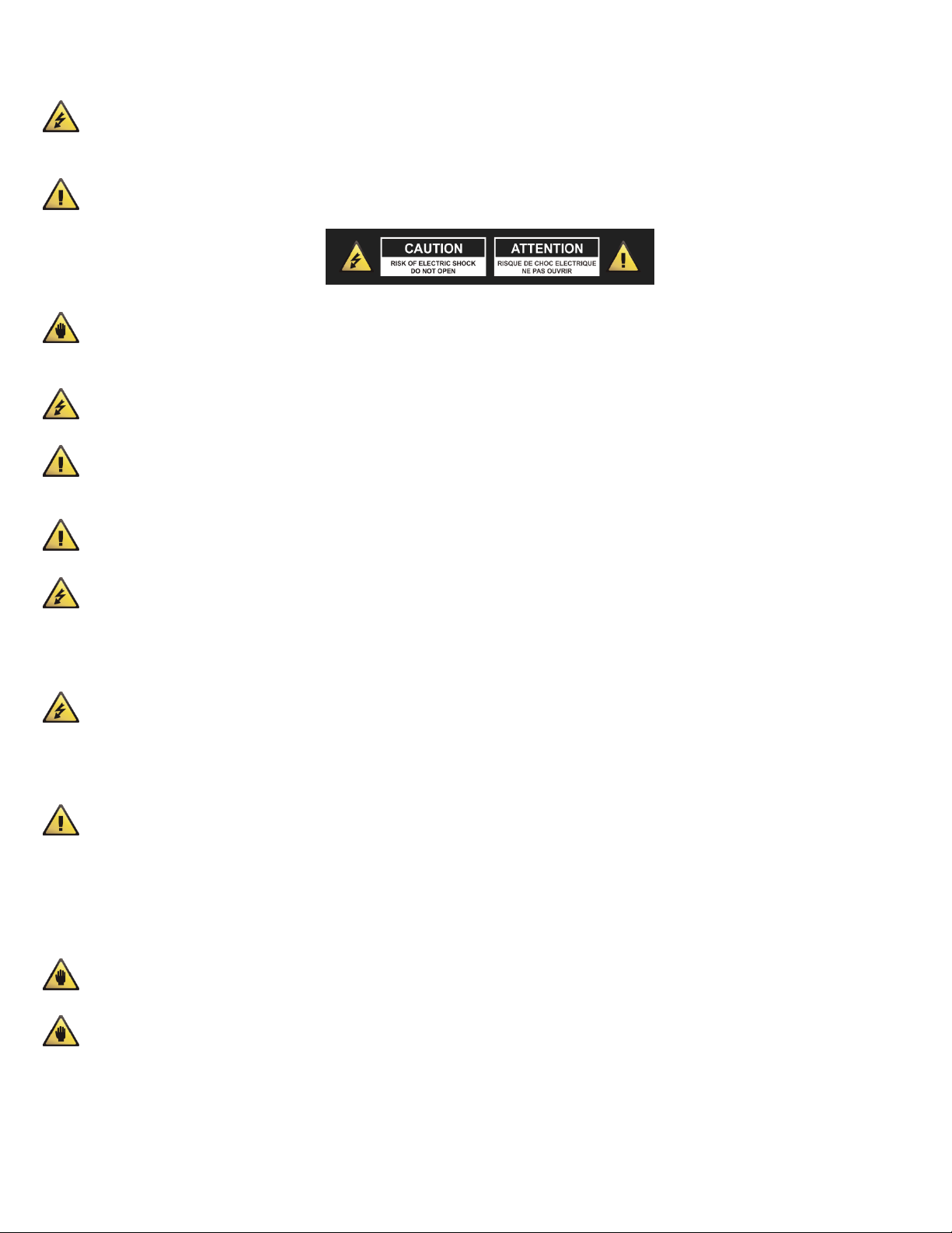
(1). PEAK LED INDICATOR
This LED indicators lets you check the level of the signal input to the channel.
The peak indicator lights when the input signal reaches 5dB below the
channel’s clipping point. This indicator shows the level of the Post-EQ /
pre-fader signal. If the PEAK indicator lights more than briefly on high-level
transients, you should use the GAIN control to decrease the input sensitivity
of the channel. If this does not work, reduce the output level of the connected
source.
(2). GAIN CONTROL
According to the level of the input signal, use this knob to adjust the input to
an appropriate level. The best balance of S/N and dynamic range will be
achieved if you adjust the GAIN control so that the peak indicator lights
occasionally. This control adjusts the channel’s mic input sensitivity between
-50dB and -6dB and the line input sensitivity between -30dB and +14dB. The
mono/stereo combination input channels have a sensitivity of +20dB to
-20dB.
(3). HPF (High-Pass Filter, cut frequencies below 75Hz)
This switch toggles the HPF on or off. To turn the HPF on, press the switch in
( ).
(4). 3 BAND EQUALIZER CONTROLS
This is a 3-band equalizer with center frequencies, range and type as shown
below. The frequency response is flat when all knobs are in the “0” position.
(5). AUX CONTROLS
This knobs control the level of the signals sent to AUX bus.
(6).PRE/POST SWITCH
This button determines whether the AUX signal is Pre or Post fader. Pre
means not affected by the position of the channel fader. Post means is
affected by the position of the channel fader.
(7). EFX CONTROLS
This knobs control the level of the signals sent to EFX bus. The channel signals mixed by this bus have their overall level
set by the EFX SEND Control to the EFX SEND jack on the front panel. The EFX bus signal is also fed into the internal
digital signal processor. Since this control is placed after the channel fader, the signal level will be affected by the
channel fader setting.
6
Page 7

FRONT PANEL CONTROLS – CHANNEL CONTROL SECTION (continued)
(8). PAN/BAL CONTROL
PAN (Mono Channel)
This control pans the channel signal across the master L and R buses, thus determining the perceived position of the
sound from that channel in the output stereo sound field. If a PAN control is set all the way to the left, for example, the
sound from that channel will be heard from the left speaker system only. If it is set all the way to the right, the sound
will be heard from the right speaker system only. Intermediate settings will cause the sound to appear at corresponding
locations in the stereo sound field.
BALANCE (Stereo Channel)
This control adjusts the balance or the L/R position of the stereo input signal. Turning the BALANCE control to the left of
center moves the apparent source toward the MAIN MIX L moves the source toward the MAIN MIX R bus.
(9). MUTE/ALT 3/4 SWITCH
When the Mute/ALT 3/4 switch is depressed, a channel output will be routed to the ALT 3/4 output instead of the MAIN
L/R output. ALT 3/4 bus offers you a second independent stereo sub mix with its own sub master stereo fader.
(10). PFL SWITCH
When this switch is depressed, the channel input signal can be routed to the PFL bus. This switch allows you to monitor
the pre-fader channel input signal through headphone outputs and control room outputs.
(11). PFL INDICATOR
This indicator lights when the PFL switch is turned on.
(12). CHANNEL FADER
This is the channels main level control. It determines the level of the signal that is sent from the channel to the master
mixing and effect buses. It is the settings of the input channel faders that determine the mix, or the balance of sound
levels between the instruments or other sources connected to the inputs. When a channel is not being used, its volume
should be set at the minimum position to prevent the addition of unwanted noise to the main program signal.
7
Page 8
FRONT PANEL CONTROLS – MAIN CONTROL SECTION
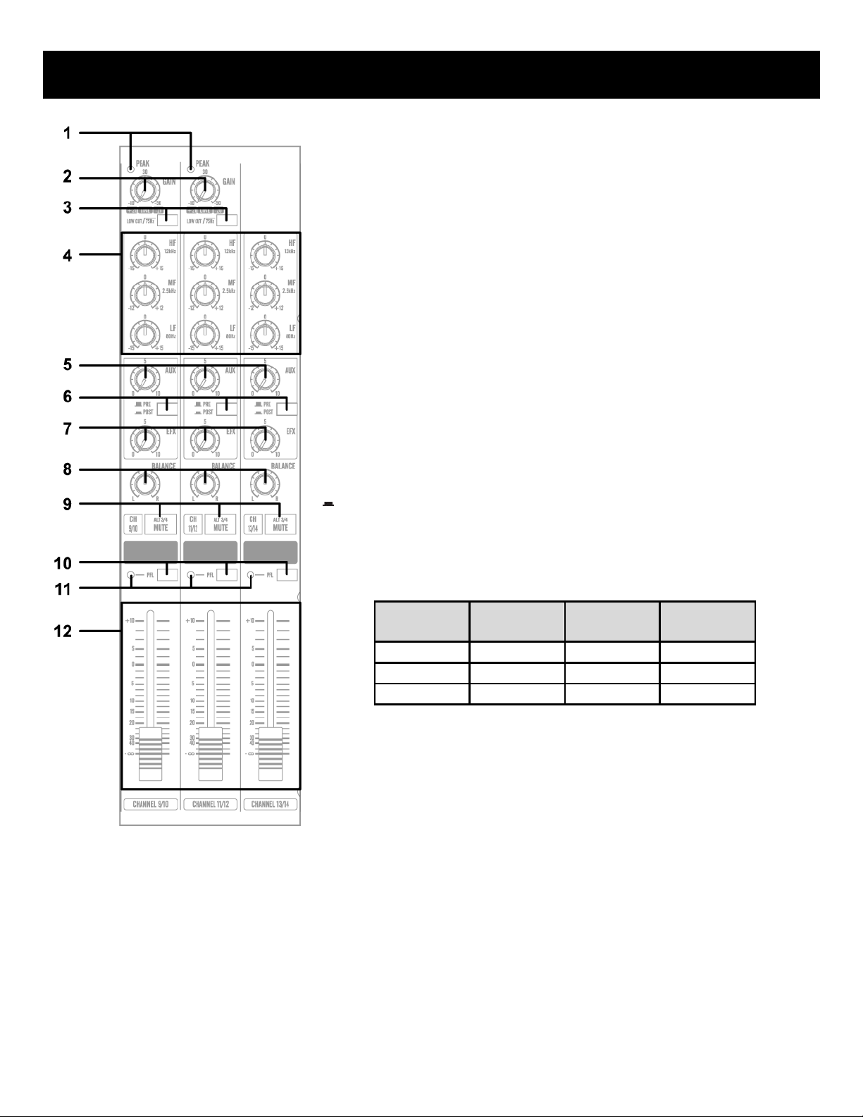
(1). VFX PROGRAM DISPLAY
The Program LED displays the number of the
selected effects program. Use the table located
above the VFX (EFX)ON/OFF switch to lookup the
desired effects.
(2). VFX PROGRAM SELECT SWITCH
This program knob selects one of the 100 built-in
digital effects, for each number you select. The VFX
programs feature a 24 Bit Digital Effects processor
with high quality, studio grade effects like Delay,
Chorus and Reverb.
(3). AUX PRE CONTROL
Adjust the level of the signal sent from the internal
digital effect to the AUX bus.
(4). VFX (EFX) ON/OFF SWITCH
This switch turns the internal digital effect on/off.
(5). PFL SWITCH
Set this switch on if you wish to output the effect
signal to the PFL bus.
(6). PFL INDICATOR
This indicator lights when the PFL switch is turned
on.
(7). EFX RTN Fader
Adjust the level of the signal sent from the internal
digital effect to the main bus.
(8). ALT 3/4 OUTPUT FADER
This fader adjusts the final level of the combined
stereo signal sent to the ALT 3/4 output jacks.
(9). MAIN L/R MASTER FADER
These faders adjust the final level of the combined
signals from all channels.
(10). TO MAIN L/R SWITCH
When this switch is on, the signal of each ALT 3/4 will
be sent to the MAIN L/R buses.
8
Page 9

FRONT PANEL CONTROLS – MAIN CONTROL SECTION (continued)
(11). Level-Meter Signal Switches (MAIN-ALT 3/4 Toggle Switch and TAPE IN Switch)
These level-meter switches, together with the channel PFL switches, select the signal that is sent through the CTRL
ROOM/HEADPHONE control to the CONTROL ROOM out jacks, the HEADPHONE jack, and the level meter. The following
illustration shows how the switch settings correspond to the signal selection.
(12). CTRL ROOM /PHONES CONTROL
Controls the level of the signal output to the HEADPHONE jack and CONTROL ROOM L and R jacks.
(13). TAPE IN CONTROL
This control adjusts the level of the playback signal that is inserted to the master mixing bus from the TAPE IN RCA
jacks on the top panel.
(14). MASTER SEND
* Master AUX Control
Adjust the level of the signal on the AUX bus to the corresponding AUX SEND jack.
* Master EFX Control
Adjust the level of the signal on the EFX bus. This is the signal that is output through the EFX SEND jack.
(15). PFL INDICATOR
This indicator lights when the PFL switch is turned on.
(16). OUTPUT LEVEL METER
A vertical row of ten LED shows the continuous output level of MAIN OUTPUT L/R. This type of display is highly visible
under poor lighting conditions. The 0 LED means an output level of +4dB for +4dB output (that’s the rated level).
(17). STEREO RETURN CONTROL
* AUX CONTROL
Adjust the level of the mixed L/R signal sent from the RETURN jack (L (MONO) and R) to the AUX bus.
* MAIN CONTROL
Adjust the level of the mixed L/R signal sent from the RETURN jack (L (MONO) and R) to the MAIN L/R bus.
9
Page 10

FRONT PANEL CONTROLS – MAIN CONTROL SECTION (continued)
(18). POWER INDICATOR
This indicator lights when the power switch is turned on.
(19). PHANTOM POWER SWITCH
This switch toggles phantom power on or off. If you set the switch on, the mixer supplies power to all channels that
provide XLR microphone input jacks. Set this switch on when using one or more condenser microphones.
WARNING, be sure the microphone you are using is compatible or will not be affected by phantom power. Failure
to do so may result in equipment damage. Please see the notes below:
NOTE: When this switch is on, the mixer supplies DC +48V power to pins 2 and 3 of all XLR-type MIC INPUT jacks.
NOTE: Be sure to leave this switch off ( ) if you do not need phantom power.
NOTE: When the switch is pressed on ( ), be sure that only condenser microphones are connected to the XLR input
jacks. Note, however, that the switch may be left on without problem when connecting to balanced dynamic
microphones. Be sure the balanced dynamic microphone you are using is not affected by phantom power in any way
before connection is made. The same applies with ribbon microphones.
NOTE: When the switch is pressed on ( ), do not use single-ended (unbalanced) microphones or instruments into the
XLR input jacks. Do not plug instrument outputs into the XLR input jack unless you know for certain it is safe to do so.
NOTE: To avoid damage to the speakers, be sure to turn off the amplifier (or powered speakers) before turning this
switch on or off. We also recommend that you turn all controls (MAIN L/R, CTRL ROOM / HEADPHONE, etc) to minimum
settings before operating the switch, to avoid risk of loud noises that could cause hearing loss or device damage.
(20). PHANTOM POWER INDICATOR
This indicator lights when the phantom power switch is turned on.
10
Page 11
FRONT PANEL CONTROLS – INPUT/OUTPUT CONNECTORS
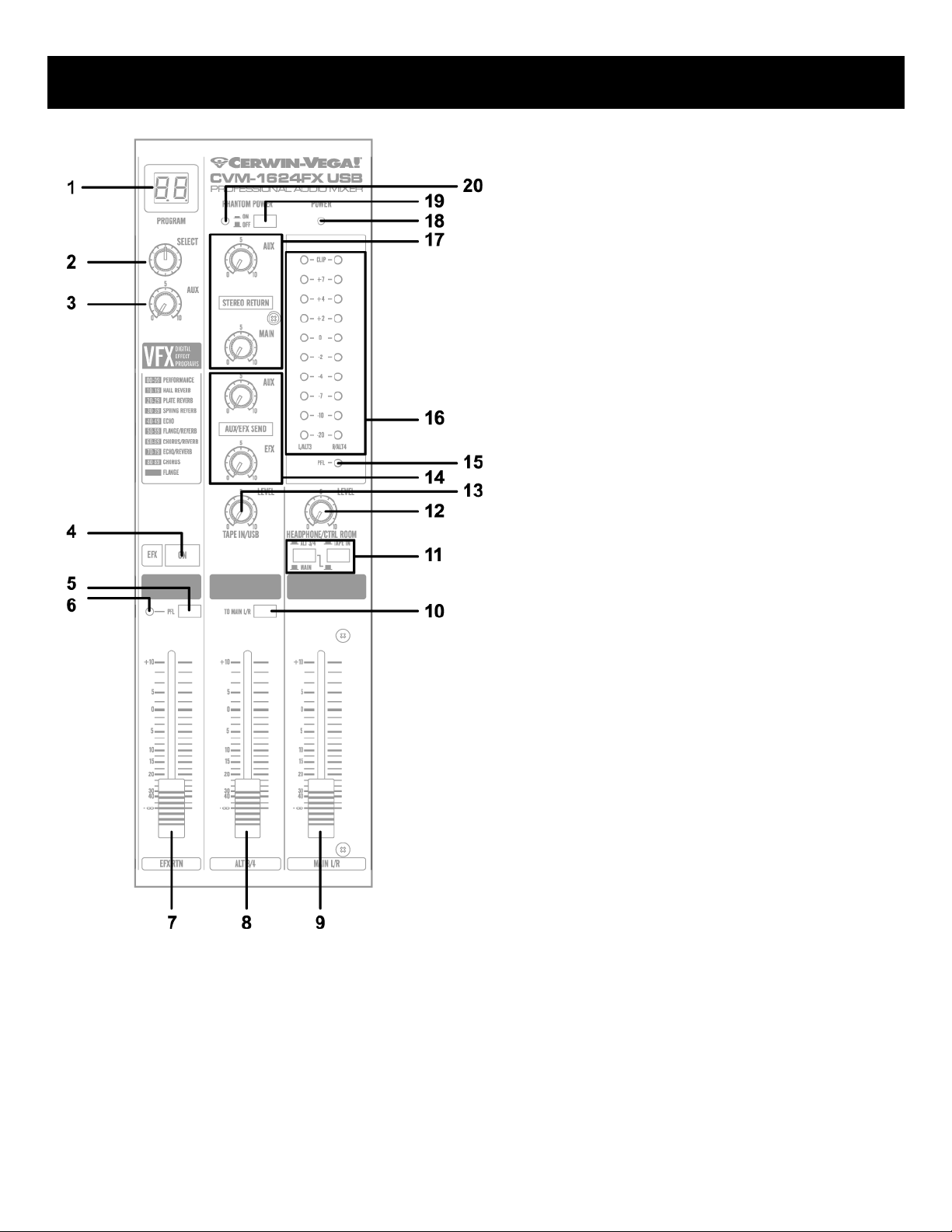
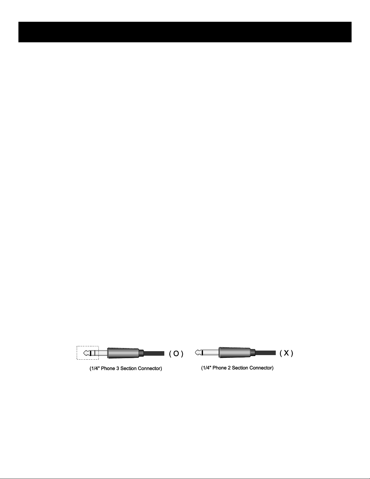
(1). Channel Input Jacks
MIC JACKS
A 3-pin XLR-type connector is used for balanced low impedance microphone inputs. (pin 1: sleeve, 2: hot, 3:cold)
BALANCED LINE IN JACKS
A standard 1/4” phone jack is used for balanced or unbalanced line level signals. Examples of line level signals include
most electronic keyboards, synthesizers, turn-tables (with appropriate pre-amps), tape decks and the line outputs from
other mixers.
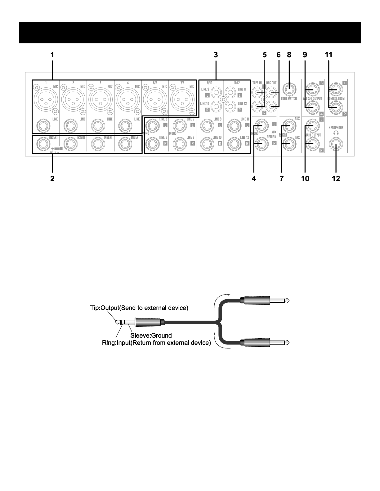
(2). CHANNEL INSERT I/O JACK
These are input/output jacks located between the head-amplifier and the high pass filter. These jacks allow you to use
graphic equalizers, compressors, noise filters, or other devices.
(3). CHANNEL INPUT JACKS
These are unbalanced stereo line input jacks. Two jack types are provided phone type and RCA pin type.
(4). STEREO RETURN L (MONO), R Jack
These are unbalanced ¼” phone-type line input jacks. The signal received by these jacks is sent to the MAIN bus and AUX
bus. These jacks are typically used to receive a return signal from an external effect (reverb, delay, etc.)
NOTE: These jacks can also be used as an auxiliary stereo input. If you connect to the L (MONO) jack only, the mixer
will recognize the signal as monaural and will propagate the identical signal on both L and R jacks.
11
Page 12
FRONT PANEL CONTROLS – INPUT/OUTPUT CONNECTORS (continued)
(5). TAPE IN JACKS
These RCA pin jacks input a stereo sound source. Use these jacks when you want to connect a CD or DAT directly to the
mixer for monitoring.
NOTE: You can adjust the signal level using the TAPE IN control in MAIN control section.
(6). REC OUT JACKS
The REC OUT jacks send the pre-fader signal from the master bus for recording by the tape deck.
(7). SEND JACKS
* AUX: These are unbalanced phone jacks-type output jack. This jack output the signal form AUX bus, respectively. You
use this jack, for example, to connect to an effector or to a cue box or other such monitoring system.
* EFX: These are unbalanced phone jacks-type output jack that output the signal form the EFFECT bus. You use this jack,
for example, to connect to an external effector
(8). FOOT SWITCH JACK
This phone input jack can connect to a foot switch. With the foot switch connected, you can use your foot to toggle the
digital effects ON and OFF.
(9). ALT 3/4 OUTPUT JACKS
These are unbalanced 1/4” phone-type output jacks which output the signals of the ALT 3/4 bus. Use these jacks to
connect to the input jack of a digital recorder, external mixer, or other such device.
(10). MAIN L/R OUTPUT JACKS
These jacks deliver stereo output of the mixer signal. You use these jacks, for example, to connect to the power
amplifiers driving your main speakers. You also use these jacks when you wish to record the signal utilizing the level
control applied by the main fader in the main control section. TRS phone-type balanced output jack.
(11). CONTROL ROOM OUTPUT JACKS
Use these stereo phone-type output jacks to connect to your monitor system.
NOTE: The signal monitored by these jacks is selected by the settings of the MAIN-ALT 3/4 toggle switch, the TAPE IN
switch, and the PFL switches on the input channels.
(12). HEADPHONE JACK
Connect for headphones. This is stereo phone-type output jack (3-conductor TRS).
NOTE: The signal monitored by these jacks is selected by the settings of the MAIN-ALT 3/4 toggle switch, the TAPE IN
switch, and the PFL switches on the input channels.
12
Page 13
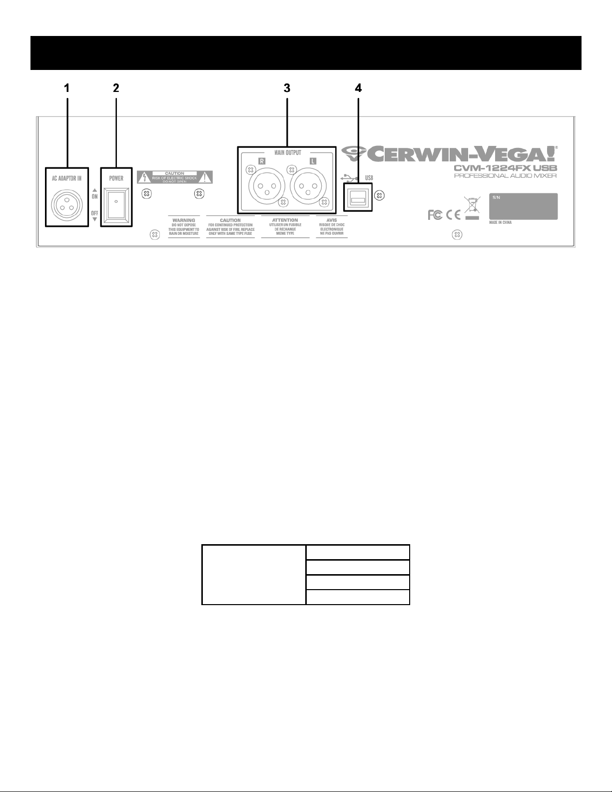
REAR PANEL CONTROLS
USB Compatibility*
Windows 7
Windows Vista
Windows XP
MAC OS X
*For compatibility on new operating
systems, please contact Customer Service.
(1). AC ADAPTOR IN CONNECTOR
Connects to the included power adaptor.
NOTE: Use only the adaptor included with this mixer. Use of a different adaptor may result in fire or electric shock.
(2). POWER SWITCH
Use this switch to turn mixer power to ON or OFF.
(3). MAIN L/R OUTPUT XLR JACK
These jacks deliver stereo output of the mixer signal. You use these jacks, for example, to connect to the power
amplifiers driving your main speakers. You also use these jacks when you wish to record the signal utilizing the level
control applied by the main fader in the main control section.
(4). USB PORT
A standard Type-A to Type-B cable is required to connect the mixer to a computer or laptop. The built-in stereo USB
audio interface allows you to record and playback from a desktop or laptop computer using virtually any digital
recording software. Payback adjustment is made using the TAPE IN/USB level knob. Connecting the audio mixer to your
computer is a simple procedure that takes just a few minutes. Since the Cerwin-Vega audio mixer is USB compliant, you
can use either a MAC or Windows-based PC. You will find detailed instructions on setting up the audio mixer in either
MAC or Windows-based computers in the following sections of this manual.
13
Page 14
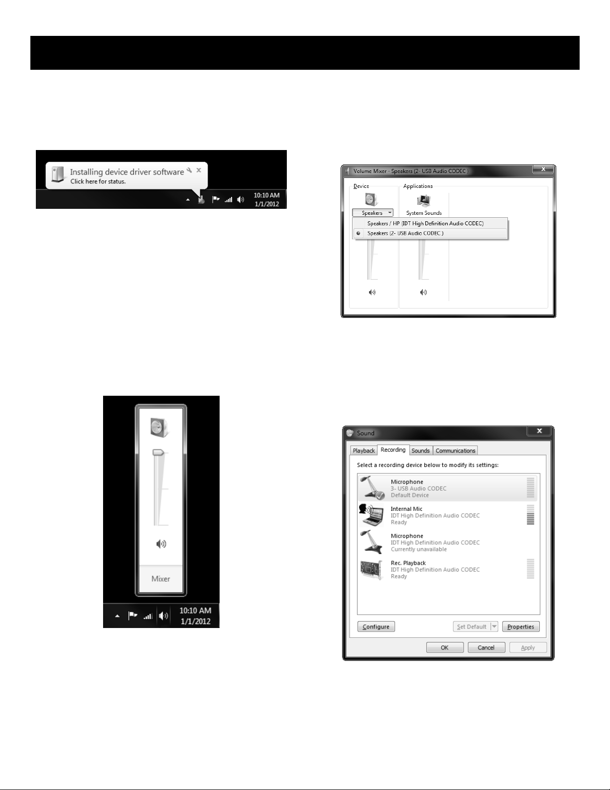
USB AUDIO INTERFACE (Windows 7)
1. The first time you plug the audio mixer into a USB
port, Windows will install the universal drivers for that
port. A balloon tip will pop-up, telling you it recognizes
the connection and will install the device driver.
2. When the drivers have finished installing, the balloon
tip will refresh itself and tell you installation is
complete.
Note: This balloon will not pop up again once the driver
has been installed.
3. Most of the time, you’ll want the output volume from
the computer at the maximum position, but sometimes
it defaults to the middle of the slider, making the output
very quiet. The volume can be increased in several
ways. The simplest is to click the loudspeaker icon in the
system tray and adjust the slider volume level.
4. Press ‘Mixer’ in the volume slider window to open up
the Volume Mixer window. To use the audio mixer as
your default output device, ensure that it is set for
speakers in the Volume Mixer window by setting the
default device to ‘USB Audio CODEC’.
5. Another way to set the default record and playback
to the audio mixer is in the Control Panel. Select the
Sound icon to open up a new window. Right-click on the
icon that lists ‘USB Audio CODEC’ and select ‘Set as
default’. A check mark on the icon indicates the device
is set to default.
6. To prevent system sounds from coming through the
audio mixer, select a different sound device for the
system default, and then choose the audio mixer
manually within your DAW software.
14
Page 15
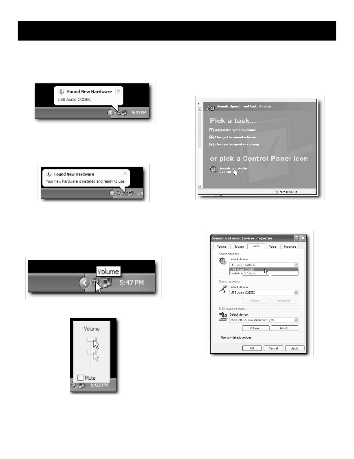
USB AUDIO INTERFACE (Windows XP)
1. The first time you plug the audio mixer into a USB
port, Windows will install the universal drivers for that
port. A balloon tip will pop-up, telling you it has found
the USB Audio codec.
2. When the drivers have finished installing, it will say
“Your new hardware is installed and ready to use”
Note: This balloon will not pop up again once the driver
has been installed.
4. To use the audio mixer as your default input/output
device (for system sounds and programs like Sound
Recorder), ensure that it is set for playback and
recording in the Properties window by setting the
default device to ‘USB Audio CODEC’. Go to Control
Panel and open Sounds, Speech and Audio Devices.
3. Most of the time, you’ll want the output volume from
the computer at the maximum position, but sometimes
it defaults to the middle of the slider, making the output
very quiet. The volume can be increased in several
ways. The simplest is to click the loudspeaker icon in the
system tray and drag the slider to the top.
A new window will appear showing a volume slider.
5. In the Properties window, set sound playback to ‘USB
Audio CODEC’. And set sound recording playback to
‘USB Audio CODEC’.
6. To prevent system sounds from coming through the
audio mixer, select a different sound device for the
system default, and then choose the audio mixer
manually within your DAW (digital audio workstation)
software.
15
Page 16
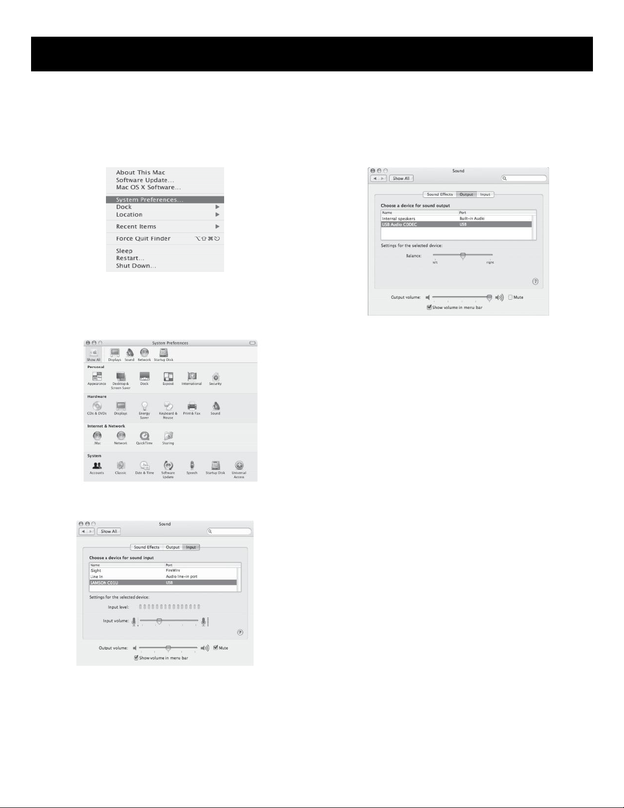
USB AUDIO INTERFACE (MAC OS X)
1. Connect the audio mixer to your MAC using a
standard USB cable. The LED will light to indicate it is
receiving USB power. The MAC will recognize the USB
audio device and automatically install a universal driver.
2. To select the audio mixer as the computer’s audio
input, open the System Preferences from the dock or
the main Apple Menu.
3. Next open the Sound preference.
4. Now, click in the Input tab and select USB Audio
CODEC. You may notice that the Volume slider sets
itself to the full level. This will allow you to have full
range using audio mixer hardware input level controls.
5. Next, click in the Output tab and select USB Audio
CODEC. You may notice that the Volume slider sets
itself to the full level. This will allow you to have full
range using audio mixer hardware MAIN Volume
control.
At this point you can begin using your audio mixer with
most any audio recording software, but you need to
select it as an input and output device within the DAW.
When selecting the inputs and outputs just look for and
select the USB Audio CODEC.
16
Page 17

POINTS TO REMEMBER
- In all cases, use good quality twin screened audio cable. Check for instability at the output.
- Always connect both conductors at both ends, and ensure that the screen is only connected at one end.
- Do not disconnect the mains earth from each piece of equipment. This is needed to provide both safety and
screen returns to the system start point.
- Equipment which has balanced inputs and outputs may need to be electrically isolated from the equipment rack
and/or other equipment, to avoid earth loops.
It is important to remember that all equipment which is connected to the mains is a potential source of hum and
interference and may radiate both electrostatic and electromagnetic radiation. In addition, the mains will also act as a
carrier for many forms of RF interference generated by electric motors, air-conditioning units, thyristor light dimmers
etc. Unless the earth system is clean, all attempts to improve hum noise levels will be futile. In extreme cases there will
be no alternative but to provide a completely separate and independent ‘technical earth’ to replace the incoming ‘noisy
earth’. However, always consults your local electricity supply authority to ensure that safety regulations are not being
infringed.
17
Page 18
CONNECTIONS
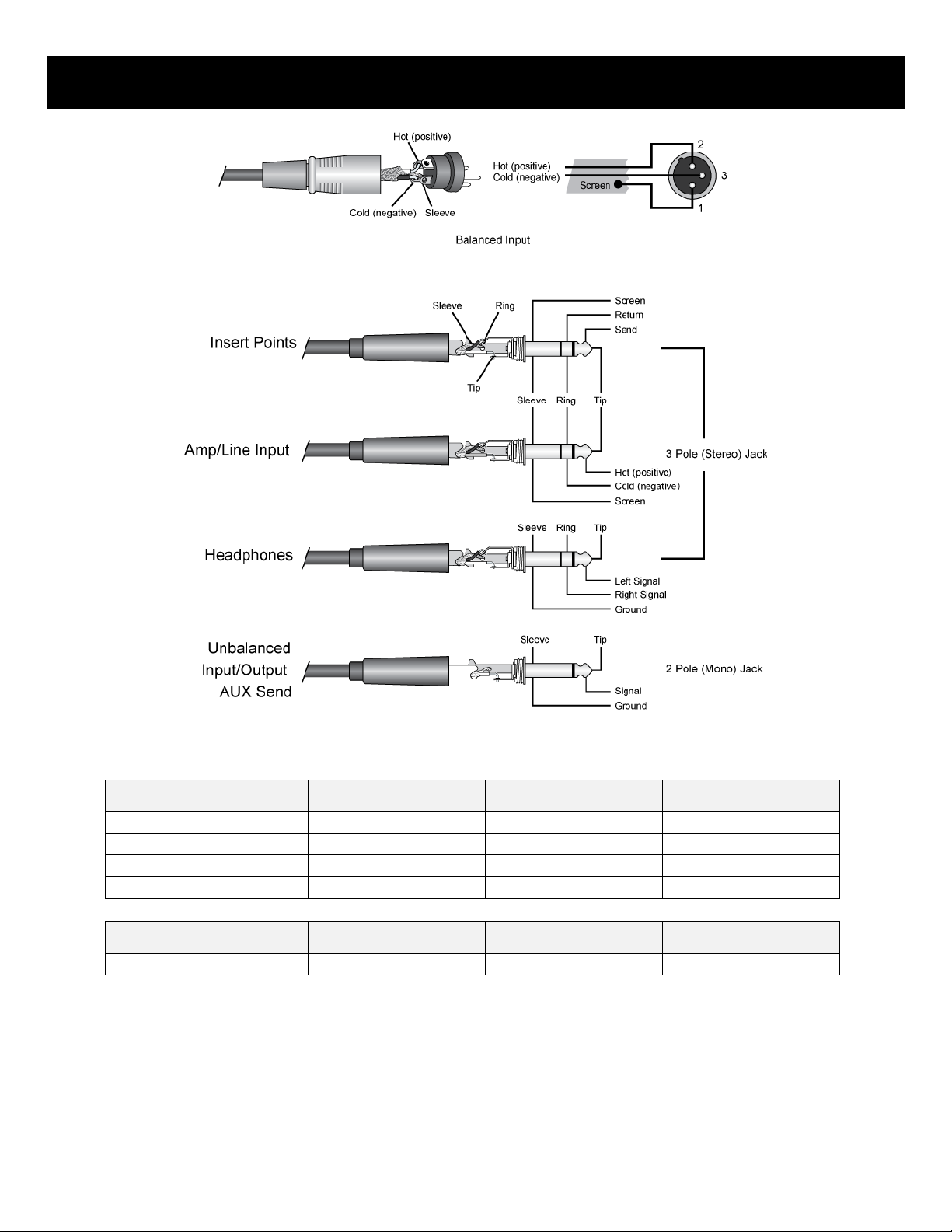
Table A (1/4” TRS)
Sleeve
Ring
Tip
Insert
Screen
Return
Send
Balanced Line
Ground
Cold (-)
Hot (+)
Unbalanced Line
Ground
n/a
Hot (+)
Headphones
Sleeve
Right
Left
Table B (XLR)
Pin 1
Pin 2
Pin 3
XLR
Shield/Ground
Cold (-)
Hot (+)
18
Page 19
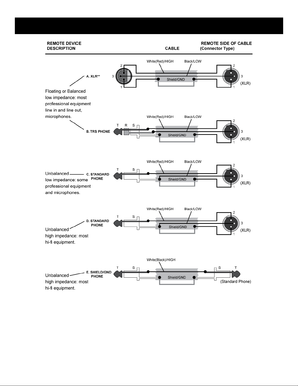
CONNECTIONS – CONNECTOR AND CABLE CONFIGURATIONS
19
Page 20
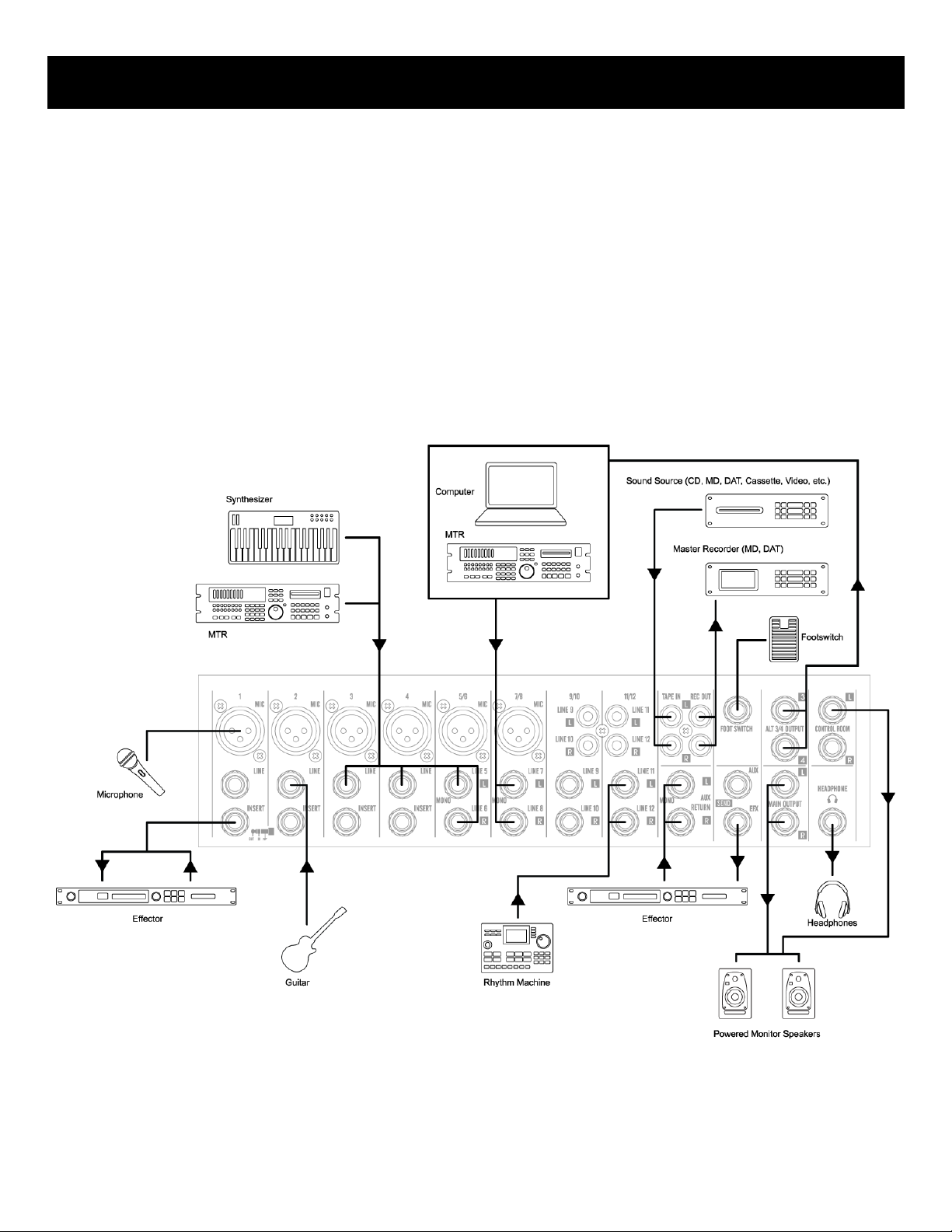
APPLICATIONS – HOME RECORDING
Setup Procedure
1. Before connecting to microphones and instruments, be sure that all devices are turned off. Also be sure that all
of the mixer’s channel fader and master control faders are set all the way down.
2. For each connection, connect one end of the cable to the relevant microphone or instrument and connect the
other end to the appropriate input jack on the mixer.
3. To avoid causing damage to the speaker, power up the devices in the following order: Peripheral devices ->
mixer -> power amps (or powered speakers)
NOTE: When shutting the system down, turn off the power in the opposite order: Power amps (powered speakers) ->
mixer -> peripheral devices.
NOTE: Where an input channel provides both a MIC INPUT jack and a LINE INPUT jack, you may use either one of these
jack but you may not use both at the same time. Please connect to only one of these jacks on each channel.
20
Page 21
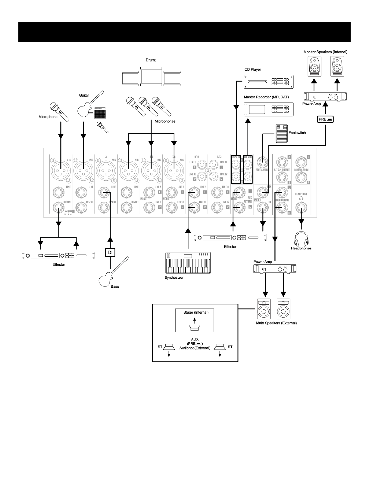
APPLICATIONS – LIVE PERFORMANCE
21
Page 22
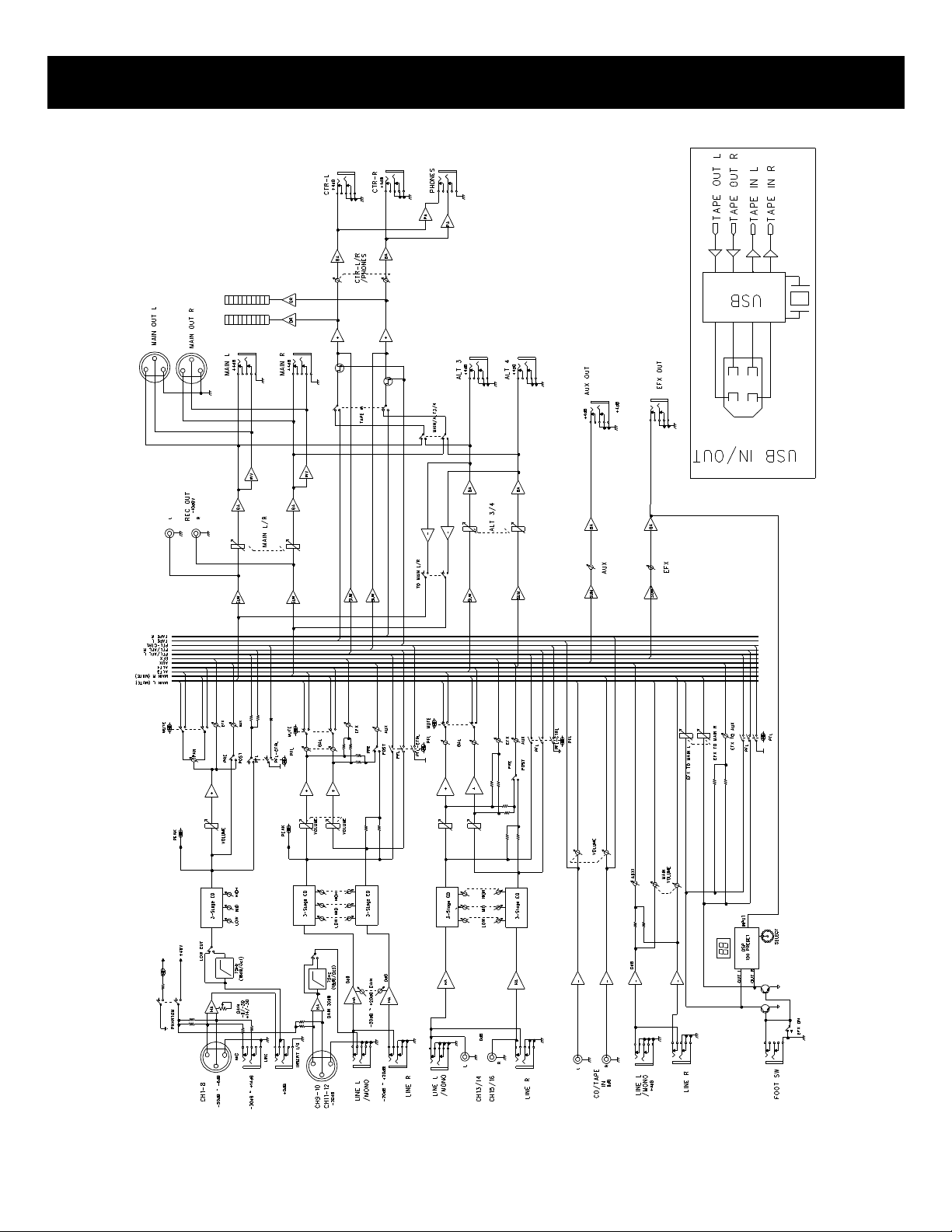
BLOCK DIAGRAM
22
Page 23

GENERAL SPECIFICATIONS
*0dB=0.775Vrms, 0dBV=1VRMS
Maximum Output Level
(0.5% T.H.D. at 1kHz)
+26dB (MAIN L/R), +20dB (ALT 3/4, AUX, EFX, CTRL ROOM)
+20dB (INSERT) more than 100mW (HEADPHONES) @ 33Ω
T.H.D.
<0.1% @ +14dB 20Hz~20kHz (MAIN L/R, ALT 3/4, AUX SEND, EFX SEND, CTRL ROOM)
Frequency Response
20Hz~20kHz, +1/-2dB (MIX L/R, ALT 3/4, AUX SEND, EFX SEND, CTRL ROOM)
Hum and Noise (Average,
20kHz LPF Rs = 150Ω)
-127dB equivalent input noise, -95dB residual noise (MAIN L/R, ALT 3/4, AUX/EFX SEND,
CTRL ROOM OUT), -88dB (MAIN L/R, ALT 3/4, AUX/EFX send, CTRL ROOM OUT) * Master
fader at nominal level and all channel fader Minimum.
Maximum Voltage Gain
74dB MIC IN to MAIN L/R, 74dB MIC IN to ALT 3/4, 66dB MIC IN to AUX (PRE)
76dB MIC IN to AUX (POST), 76dB MIC IN to EFX (REV), 80dB MIC IN TO CONTROL ROOM
52.5dB MIC IN to REC L/R, 54dB LINE IN to MAIN L/R, 54dB LINE IN to ALT 3/4
46dB LINE IN to AUX (PRE), 56dB LINE IN to AUX (POST), 56dB LINE IN to EFX (REV),
60dB LINE IN to CONTROL ROOM L/R, 44dB ST IN to MAIN L/R, 44dB ST IN to ALT 3/4
16dB AUX RETURN IN to MAIN L/R, 20dB TAPE IN to MAIN L/R
Crosstalk (at 1kHz)
-70dB between input channels, -70dB between input/output channels
Gain Control (mono Input
channel)
44dB Variable (-50dB ~ -6dB), (-30dB ~ +14dB)
Gain Control (mono/stereo
combination Input channel)
40dB Variable (-20dB ~ +20dB)
Input Channel Equalization
HIGH: 12kHz shelving, MID: 2.5kHz peaking, LOW: 80Hz shelving * turnover/roll off
frequencies: located 3dB below maximum boost/cut
LED Meters
10-segment LED x2 MAIN L/R, ALT 3/4, PFL, TAPE IN
Channel Indicators
Peak: An indicator for each channel turns on when the pre-channel fader signal is 5dB
below clipping.
Phantom Power
+48V DC
Power Supply
USA/Canada 120VAC / 60Hz
Australia 240VAC / 50Hz
Europe 230VAC / 50Hz
Power Consumption
36W
Weight
3.4 kg (7.5 lbs) CVM-1224FXUSB
5.6 kg (12.3 lbs) CVM-1624FXUSB
Dimension (W x H x D)
328 x 90 x 420 mm (12.9 x 3.5 x 16.5 in) CVM-1224FXUSB
436 x 90 x 420 mm (17.2 x 3.5 x 16.5 in) CVM-1624FXUSB
*Specifications and design subject to change without notice for improvements.
23
Page 24

SPECIFICATIONS
Input Connector
Input Impedance
Nominal
Impedance
Rated Input Level
Connector Type
CH Mic
4 kΩ
50 ~ 600 Ω
-50 dB
XLR 3-31 Type Balanced
CH Line
10 kΩ
600 Ω
-30 dB
Phone Jack (TRS)
T=Hot R=Cold S=GND
Stereo Input Mic
3 kΩ
600 Ω
-44 dB
XLR 3-31 Type Balanced
Stereo Input Line
5 kΩ
600 Ω
-20 dB
Unbalanced Phone Jack
Mono Channel Insert
Input
10 kΩ
600 Ω
0 dB
Phone Jack (TRS)
T=Out R=In S=GND
Tape In
10 kΩ
600 Ω
-10 dBV
RCA pin Jack
Output Connector
Output
Impedance
Nominal
Impedance
Rated Output
Level
Connector Type
MAIN L/R
75 Ω
10 kΩ
+4 dB
Balanced Phone Jack
ALT 3/4
75 Ω
10 kΩ
+4 dB
Unbalanced Phone Jack
CTRL Room Out
75 Ω
10 kΩ
+4 dB
Unbalanced Phone Jack
AUX Send
75 Ω
600 Ω
+4 dB
Unbalanced Phone Jack
Mono Channel Insert
Output
100 Ω
10 kΩ
0 dB
Phone Jack (TRS)
T=Out R=In S=GND
REC Out
600 Ω
10 kΩ
-10 dBV
RCA pin Jack
HEADPHONES Out
100 Ω
33 Ω
3mW
Stereo Phone Jack
INPUT
OUTPUT
*Specifications and design subject to change without notice for improvements.
24
Page 25

WARRANTY
Thank you for choosing one of Gibson Pro Audio’s brands (Stanton, KRK, or Cerwin Vega!).
Your satisfaction is extremely important to us. We proudly stand behind the quality of our work and appreciate that you
put your trust in us. Registering your merchandise will help us guarantee that you are kept up to date on our latest
advances.
To Register Merchandise Purchased from an Authorized Gibson Pro Audio Dealer in the U.S.:
Please go to: http://www.gibson.com and register online.
Or you may send your warranty card to:
Gibson Customer Service
309 Plus Park Blvd.
Nashville, TN 37217
If you have any questions you may contact customer service at:
1-800-4GIBSON (1-800-444-2766)
e-mail: service@gibson.com
FOR MERCHANDISE PURCHASED FROM AN AUTHORIZED GIBSON PRO AUDIO DISTRIBUTOR OUTSIDE OF THE US, PLEASE
CONTACT THE DISTRIBUTOR FROM WHOM YOU PURCHASED YOUR MERCHANDISE FOR TO REGISTER YOUR WARRANTY
AND FOR HANDLING AND RESOLUTION OF ALL WARRANTY-RELATED ISSUES.
Gibson Pro Audio Warranty
If at any time your Gibson Pro Audio product (which includes Stanton, KRK, or Cerwin Vega! brands) malfunctions as a
result of faulty materials or workmanship, Gibson Pro Audio or one of Gibson Pro Audio’s Authorized Service Centers in
the US will repair the defect(s) or replace the merchandise, as it deems appropriate at its sole discretion.
Warranty Period (from date of Purchase as listed on the Bill of Sale):
Stanton
One (1) year for all Stanton products.
KRK
Three (3) years from all studio monitors.
One (1) year all headphones, computer audio devices, including room correction devices.
Cerwin Vega!
Five (5) years for all passive speaker systems.
Three (3) years for all active speaker systems.
Three (3) years for all mixers.
Gibson will warrant all replacement parts and repairs for ninety (90) days from the date of original shipment.
In the unlikely event that your merchandise is destroyed, lost or damaged beyond repair while in the possession of
Gibson or one of Gibson Pro Audio’s Authorized Service Centers for repair, Gibson will replace that merchandise with
one of the same or most similar style of a value not in excess of the original purchase price of your merchandise. Any
insurance covering the merchandise, including but not limited to collector's value insurance, must be carried by owner
at owner's expense.
For the fastest and safest merchandise return, please use the original shipping carton and packaging materials. Gibson
cannot be responsible for any damages incurred during the shipping process due to poor or inadequate packing.
25
Page 26

WARRANTY (continued)
THIS WARRANTY IS EXTENDED TO THE ORIGINAL RETAIL PURCHASER ONLY AND MAY NOT BE TRANSFERRED OR
ASSIGNED TO SUBSEQUENT OWNERS. IN ORDER TO VALIDATE YOUR WARRANTY, AND AS A CONDITION PRECEDENT TO
WARRANTY COVERAGE HEREUNDER, YOU MUST REGISTER YOUR WARRANTY WITHIN FIFTEEN (15) DAYS FOLLOWING
THE ORIGINAL DATE OF PURCHASE.YOUR PROOF OF PURCHASE OR SALES RECEIPT MUST ACCOMPANY ALL REQUESTS
FOR WARRANTY COVERAGE.
This warranty is subject to the following limitations:
THIS WARRANTY DOES NOT COVER
1. Any merchandise that has been altered or modified in any way or upon which the serial number has been tampered
with or altered.
2. Any merchandise whose warranty card has been altered or upon which false information has been given.
3. Any merchandise that has been damaged due to misuse, negligence, or improper operation.
4. Any merchandise that has been damaged by accident, flood, fire, lightening, or other acts of God.
5. Shipping damage of any kind.
6. Any merchandise that has been subjected to extremes of humidity or temperature.
7. Any merchandise that has been purchased from an unauthorized dealer, or upon which unauthorized repair or service
has been performed.
GIBSON MAKES NO OTHER EXPRESS WARRANTY OF ANY KIND WHATSOEVER. ALL IMPLIED WARRANTIES, INCLUDING
WARRANTIES OF MERCHANTABILITY AND FITNESS FOR A PARTICULAR PURPOSE, EXCEEDING THE SPECIFIC PROVISIONS
OF THIS WARRANTY ARE HEREBY DISCLAIMED AND EXCLUDED FROM THIS WARRANTY. SOME STATES AND/OR
COUNTRIES DO NOT ALLOW THE EXCLUSION OR LIMITATION OF IMPLIED WARRANTIES SO THAT THE ABOVE MAY NOT
APPLY TO YOU.
GIBSON SHALL NOT BE LIABLE FOR ANY SPECIAL, INDIRECT CONSEQUENTIAL, INCIDENTAL OR OTHER SIMILAR DAMAGES
SUFFERED BY THE PURCHASER OR ANY THIRD PARTY, INCLUDING WITHOUT LIMITATION, DAMAGES FOR LOSS OF
PROFITS OR BUSINESS OR DAMAGES RESULTING FROM USE OR PERFORMANCE OF THE MERCHANDISE, WHETHER IN
CONTRACT OR IN TORT, EVEN IF GIBSON OR ITS AUTHORIZED REPRESENTATIVE HAS BEEN ADVISED OF THE POSSIBILITY
OF SUCH DAMAGES, AND GIBSON SHALL NOT BE LIABLE FOR ANY EXPENSES, CLAIMS, OR SUITS ARISING OUT OF OR
RELATING TO ANY OF THE FOREGOING.
FOR MERCHANDISE PURCHASED FROM AN AUTHORIZED GIBSON PRO AUDIO DISTRIBUTOR OUTSIDE OF THE US, PLEASE
CONTACT THE DISTRIBUTOR FROM WHOM YOU PURCHASED YOUR MERCHANDISE FOR THE HANDLING AND
RESOLUTION OF ALL WARRANTY ISSUES. FOR THESE PURCHASES, THE ABOVE-DESCRIBED WARRANTY IS NOT
APPLICABLE.
26
Page 27

WARRANTY (continued)
How to Obtain Warranty Service
Warranty Service outside the United States:
To initiate a warranty repair, please contact the Authorized Gibson Pro Audio distributor from whom you purchased
your merchandise, and follow the distributor’s return/warranty policy.
Warranty Service for Merchandise Purchased from an Authorized Gibson Pro Audio Dealer in the U.S:
In the event of malfunction of your Gibson Pro Audio merchandise, the Dealer or Owner must call Customer Service @
1-800-4GIBSON (1-800-444-2766) and obtain a Return Authorization number from the customer service agent. No
merchandise may be returned to Gibson without such prior Return Authorization, and the Return Authorization number
must be written on the outside of the shipping package. The Customer Service agent will provide the address and
additional shipping instructions. Owner must ship the merchandise, freight, and insurance pre-paid to the address
provided by the customer service representative. Only Authorized Gibson Pro Audio Service Centers may perform
warranty service and any service performed by unauthorized persons will void this warranty. Gibson disclaims liability
for defects or damage caused by services performed by unauthorized persons or non-warranty service not performed by
Gibson or an Authorized Gibson Pro Audio Service Center.
When contacting Gibson, you must include a complete written description of the malfunction of the merchandise. If
non-warranty work is required or recommended, a quotation will be issued and must be approved by you before any
non-warranty work is commenced. You should consider quotations obtained for non-warranty work immediately and
advise the Authorized Gibson Pro Audio Service Center or Gibson of your wishes. You are not required to purchase
non-warranty work in order to obtain service on materials covered by this warranty. Following its inspection of
merchandise upon its arrival, Gibson or the Authorized Gibson Pro Audio Service Center will advise you or your dealer of
the approximate date of completion. The repaired merchandise or part will be returned to you or your dealer, freight
collect insured.
No representative or other person is authorized to assume for Gibson any liability except as stated in this warranty. This
warranty gives you specific rights which vary from state to state or from country to country.
For further information, write:
Customer Service Dept.,
Gibson Customer Service
309 Plus Park Blvd.
Nashville, TN 37217
Or call:
1-800-4GIBSON
27
Page 28

GLOSSARY
attenuate to reduce or make quieter. decrease the signal level
auxiliary (aux) send an output signal from the mixer to supplemental equipment that provide additional
capabilities. typically the feeds to the mix are implemented on rotary level controls. an aux
return on the mixer is intended to connect to the output of the supplemental equipment.
balance the relative levels of the left and right channels of a stereo signal.
balanced a method of audio connection which ‘balances’ the wanted signal between two wires and a
screen which carries no signal. any interference is picked up equally by the two wires, which
results in cancellation of the unwanted signal.
clipping the onset of severe distortion in the signal path, usually caused by the peak signal voltage being
limited by the circuit’s power supply voltage.
DAT Digital Audio Tape, a cassette-based digital recording format.
dB (decibel) a ratio of two voltages or signal levels, expressed by the equation dB=20Log10 (V1/V2). Adding
the suffix ‘u’ denotes the ratio is relative to 0.775V RMS.
DI (direct injection) the practice of connecting an electric musical instrument directly to the input
of the /DI Box mixing console, rather than to an amplifier and loudspeaker which is covered by a
microphone feeding the console.
direct output a post fade line level output from the input channel, bypassing the summing amplifiers, typically
for sending to individual tape tracks during recording.
equalizer a device that allows the boosting or cutting of selected bands of frequencies in the signal path.
fader a linear control providing level adjustment.
feedback the `howling’ sound caused by bringing a microphone too close to a loudspeaker driven from its
amplified signal.
foldback a feed sent back to the artistes via loudspeakers or headphones to enable them to monitor the
sounds they are producing.
frequency response the variation in gain of a device with frequency.
gain the amount of amplification in level of the signal.
headroom the available signal range above the nominal level before clipping occurs.
highpass filter a filter that rejects low frequencies and passes only high frequencies. the cut-off frequency
determines the limit that frequencies are rejected or allowed to pass through.
impedance balancing a technique used on unbalanced outputs to minimize the effect of hum and interference when
connecting to external balanced inputs.
28
Page 29

GLOSSARY (continued)
insert a break point in the signal path to allow the connection of external devices, for instance signal
processors or other mixers at line level signals. Nominal levels can be anywhere between -10dBu
to +6dBu, usually coming from a low impedance source.
pan (pot) abbreviation of ‘panorama’: controls levels sent to left and right outputs.
peaking the point at which a signal rises to its maximum instantaneous level, before falling back down
again. It can also describe an equalizer response curve affecting only a band of frequencies, (like
on a graphic equalizer), “peaking” at the centre of that band.
peak LED a visual indication of the signal peaking just before the onset of clipping.
PFL a function that allows the operator to monitor the pre-fade signal (pre-fade listen) in a channel
independently of the main mix.
phase a term used to describe the relationship of two audio signals. In-phase signals reinforce each
other, out-of-phase signals result in cancellation.
polarity a term used to describe the orientation of the positive and negative poles of an audio
connection. Normally connections are made with positive to positive, negative to negative. If
this is reversed, the result will be out-of-phase signals (see ‘phase’ above).
post-fade the point in the signal path after the monitor or master fader and therefore affected by fader
position.
pre-fade the point in the signal path before the monitor or master fader position and therefore
unaffected by the fader position.
rolloff a fall in gain at the extremes of the frequency response.
shelving an equalizer response affecting all frequencies above or below the break frequency i.e. a
highpass or lowpass derived response.
spill acoustic interference from other sources.
transient a momentary rise in the signal level.
unbalanced a method of audio connection which uses a single wire and the cable screen as the
signal return. This method does not provide the noise immunity of a balanced input (see above).
+48V the phantom power supply, available at the channel mic inputs, for condenser
microphones and active DI boxes.
29
Page 30
CVM-1224FXUSB
CVM-1624FXUSB
TABLE DE MIXAGE AUDIO PROFESSIONNELLE
30
Page 31

MESURES DE SECURITE IMPORTANTES
ATTENTION : LE SYMBOLE DE L’ÉCLAIR À L’INTÉRIEUR D’UN TRIANGLE ÉQUILATÉRAL, EST DESTINÉ À ALERTER L’UTILISATEUR DE
LA PRÉSENCE DE PIÈCES SOUS TENSION NON ISOLÉES DANS LE PRODUIT, D’UNE MAGNITUDE POUVANT CONSTITUER UN
RISQUE D’ÉLECTROCUTION.
AVERTISSEMENT : LE SYMBOLE DU POINT D’EXCLAMATION, DANS UN TRIANGLE ÉQUILATÉRAL, EST DESTINÉ À ALERTER
L’UTILISATEUR QUE D’IMPORTANTS CONSEILS DE FONCTIONNEMENT ET DE MAINTENANCE (RÉPARATION) SONT FOURNIS DANS
LA DOCUMENTATION ACCOMPAGNANT LE PRODUIT.
REMARQUE : LE SYMBOLE D'UNE MAIN DANS UN TRIANGLE ÉQUILATÉRAL EST DESTINÉ À ALERTER L'UTILISATEUR DE LA
PRÉSENCE D'INSTRUCTIONS ET D'INFORMATIONS SPECIFIQUES CONCERNANT L'UTILISATION DE L'APPAREIL QUI DOIVENTT ÊTRE
LUES COMPLÈTEMENT AVANT D'UTILISER L'APPAREIL POUR LA PREMIÈRE FOIS.
ATTENTION : POUR RÉDUIRE LE RISQUE D’INCENDIE ET DE CHOC ÉLECTRIQUE, NE DÉPOSEZ AUCUN CAPOT ET N’OUVREZ PAS
L’APPAREIL. AUCUN COMPOSANT À L’INTERIEUR NE PEUT ÊTRE RÉPARÉ PAR L’UTILISATEUR. TOUTE RÉPARATION DOIT ÊTRE
EFFECTUÉE PAR UN TECHNICIEN DE MAINTENANCE QUALIFIÉ.
AVERTISSEMENT : AVANT DE CONNECTER ET D’UTILISER L’APPAREIL, LISEZ ET RESPECTEZ TOUTES LES CONSIGNES DE SÉCURITÉ
ET LES INSTRUCTIONS D’UTILISATION. CONSERVEZ CE GUIDE D’UTILISATION POUR TOUTE RÉFÉRENCE ULTÉRIEURE. TOUS LES
AVERTISSEMENTS SUR L’APPAREIL ET SON EMBALLAGE DOIVENT ÊTRE LUS ET RESPECTÉS.
AVERTISSEMENT : ce produit contient des agents chimiques susceptibles, selon l’état de Californie, de causer le cancer et/ou
des déficiences congénitales ou d’autres anomalies liées à la reproduction.
ATTENTION : Pour réduire tout risque d’incendie ou d’électrocution, n’exposez pas ce produit à la pluie ou à l’humidité.
N’utilisez ce produit près d’une source d’eau, telle que baignoire, bac de lavage, évier, cuve de lessivage, dans un sous-sol
humide ou près d’une piscine. Débranchez toujours l’appareil de la prise secteur avant de le nettoyer. N’utilisez jamais de
diluant, liquides de nettoyage, solvants ou chiffons imprégnés de produits chimiques. Pour le nettoyage, utilisez toujours un
chiffon doux et sec. Débranchez cet appareil pendant les orages ou si vous n’allez pas l’utiliser pendant une longue période.
ATTENTION : L’unité doit être placée de sorte qu’elle ne gêne pas sa propre ventilation. Par exemple, elle ne devrait pas être
placée sur un lit, un sofa, une couverture ou une surface semblable qui peut bloquer les fentes de ventilation ; ou placée dans
un endroit encastré, comme une bibliothèque ou une armoire qui peuvent empêcher la circulation d’air par les fentes
d’aération. L’unité devrait être placée loin de toute source de chaleur telle que radiateurs, bouches de chauffage, cuisinières et
autres appareils (y compris des amplificateurs) qui produisent de la chaleur. Ne placez au dessus ou à côté de l’appareil aucune
source de flamme nue, telle que des chandelles allumées.
AVERTISSEMENT : Évitez de placer l’appareil sur surface, chariot, support, trépied, étagère ou table instable. L’appareil pourrait
tomber et causer de graves blessures à des enfants et adultes et endommager le produit même. Utilisez seulement chariot,
support, trépied ou table recommandée par le fabricant ou vendue avec le produit. L’accrochage du produit à un mur ou au
plafond doit respecter les instructions fournies par le fabricant et les accessoires montés doivent être ceux conseillés par le
fabricant. Déplacez le chariot et l’appareil avec beaucoup de précaution. Les arrêts brutaux, les poussées trop fortes et les
surfaces irrégulières peuvent renverser l’ensemble. Utilisez seulement un chariot, socle, trépied, support ou table
recommandée par le fabricant ou vendue avec l’appareil. Quand un chariot est utilisé, soyez prudent lorsque vous déplacez
l’ensemble chariot/appareil pour éviter les blessures en cas de renversement.
REMARQUE : Si l’appareil est endommagé de manière irréparable ou atteint la fin de sa vie, suivez la règlementation locale
concernant l’élimination des produits électroniques.
REMARQUE : Cerwin-Vega ne peut être tenue responsable des dommages et/ou perte de données causées par une mauvaise
utilisation de l'appareil et/ou des applications fournies avec.
31
Page 32

MESURES DE SECURITE IMPORTANTES
POUR EVITER LES CHOCS ÉLECTRIQUES, INTRODUISEZ LA LAME LA PLUS LARGE DE LA FICHE DANS LA BORNE CORRESPONDANTE
DE LA PRISE ET POUSSEZ JUSQU’AU FOND.
ENGLISH: The apparatus shall be connected to a Mains socket outlet with a protective earthing connection.
GERMAN: Das Gerät ist eine Wandsteckdose mit einem Erdungsleiter angeschlossen werden.
FRENCH: L’appareil doit être connecté à une prise secteur avec connexion à la terre.
SPANISH: El aparato estará conectado a una toma de red eléctrica con una conexión a tierra.
ITALIAN: L’apparecchio deve essere collegato a una presa di rete con una connessione a terra protettiva.
1. L’appareil ne doit être branché qu’à une alimentation électrique de tension et fréquence marquées sur le boîtier.
2. Évitez que le cordon ne soit piétiné ou pincé, surtout au niveau des fiches, prises de courant, et au point de leur sortie de
l’appareil.
3. N’essayez pas de contourner la fonction de sécurité de la fiche polarisée ou de terre. Une fiche polarisée comporte deux
lames dont l’une est plus large que l’autre. Une fiche de mise à la terre comporte deux lames et une troisième broche de mise à
la terre,
la lame large ou la broche de mise à la terre est destinée pour votre sécurité . Si vous ne parvenez pas à insérer entièrement la
fiche dans une prise de courant, contactez votre électricien qualifié pour qu’il remplace votre prise de courant obsolète.
4. Si la fiche d’alimentation de ce produit comprend un fusible, ce dernier ne doit être remplacé que par un fusible de valeur de
rupture identique ou inférieure.
5. N’utilisez jamais un câble d’alimentation endommagé ou usé, cela peut présenter un risque grave d’exposer des tensions
mortelles.
6. Débranchez l’appareil de la prise secteur s’il ne va pas être utilisé pendant une longue période.
7. Utilisez uniquement des pièces ou des accessoires recommandés par le fabricant.
NE TENTEZ PAS DE REPARER CET APPAREIL VOUS-MEME. EN CAS DE PROBLÈME, S’ADRESSER À UN PERSONNEL TECHNIQUE
QUALIFIÉ.
Lors tout entretien ou réparation, assurez-vous que le technicien utilise les pièces de rechange agréées par le fabricant ou
qu’elles présentent les mêmes caractéristiques que les pièces d’origine, et demandez au technicien de procéder à un contrôle
de sécurité pour s’assurer que le produit est en bon état de fonctionnement.
TOUTES LES SUBSTITUTIONS NON AUTORISEES PEUVENT RESULTER EN INCENDIE, CHOCS ELECTRIQUES OU AUTRES RISQUES.
ATTENTION POUR EVITER LES CHOC ELECTRIQUES, INTRODUIRE LA LAME LA PLUS LARGE DE LA FICHE DANS LA BORNE
CORRESPONDANTE DE LA PRISE ET POUSSER JUSQ’AU FOND.
Cette unité doit être entretenue par un personnel qualifié dans les cas suivants :
Le cordon ou la prise d’alimentation a été endommagée
Des objets ou un liquide a pénétré à l’intérieur de l’appareil
L’unité a été exposée à la pluie ou à un liquide quelconque
L’appareil semble ne pas fonctionner normalement ou sa performance s’est dégradée
L’appareil est tombé ou le boîtier est endommagé.
CERTIFICATION RÉGLEMENTAIRE
Cerwin-Vega déclare sous sa seule responsabilité que l'appareil, auquel se réfère cette déclaration, est conforme aux normes
suivantes :
La déclaration de conformité peut être obtenue auprès du représentant agréé européen à l’adresse Gibson Europe BV - Kamerlingh
Onnesweg, 2 - 4131 PK Vianen - The Netherlands Tel : +31 347 32 40 10 - Fax : +31 347 32 40 15
Cet appareil numérique de la classe B est conforme à la norme NMB-003 du Canada.
32
Page 33

INTRODUCTION
DEBALLAGE ET INSTALLATION
CARACTERISTIQUES
Nous tenons à vous remercier pour votre achat d’une table de mixage audio professionnelle de la nouvelle série CV de
Cerwin-Vega ! Conçu pour une reproduction sonore de qualité, la série CV de tables de mixage audio professionnelles
offre un son de haute qualité à un prix abordable. La série CV de tables de mixage offre un niveau de fiabilité et
d'efficacité qui en fait la solution parfaite pour tous les DJ, musiciens et ingénieurs de son. Bienvenue à un nouveau
niveau de performance sonore de qualité professionnelle !
Bien que votre nouvelle table de mixage ne soit ni compliquée à installer ni difficile à utiliser, nous vous recommandons
de consacrer quelques minutes de votre temps pour lire le présent manuel afin d’effectuer correctement le câblage
nécessaire à l’installation et de vous familiariser avec les caractéristiques de l'appareil. Déballez l'appareil avec
précaution et veillez à conserver le carton et autres matériaux d'emballage. Ces derniers peuvent servir pour le
déplacement de l'appareil et sont nécessaires pour expédier l'appareil pour réparation. Ne placez jamais l'appareil à
proximité d'un radiateur, en face de bouches de chauffage, en plein soleil, dans un endroit d'humidité excessive ou
poussiéreux afin d’éviter tout dommage et pour garantir une longue utilisation fiable. Connectez l'appareil aux
composants du système selon la description fournie dans les pages suivantes.
• 4 entrées ligne mono et 4 stéréo avec 6 entrées micro XLR (12 canaux CVM-1224FXUSB)
• 8 entrées ligne mono et 4 stéréo avec 10 entrées micro XLR (16 canaux CVM-1624FXUSB)
• Connecteurs L/R (Gauche/Droite) ¼", XLR et ALT 3/4 ¼" de sortie
• Egaliseur de canal 3 Bandes conçu pour ± 15 dB (HF, LF) et de ± 12 dB (MF) de contrôle sur le canal d'entrée
• Interrupteur d'alimentation fantôme (+48 V) pour une connexion de microphones à condensateur qui
nécessitent généralement une alimentation externe
• Témoin de crête pour vérifier le signal d'entrée de chaque canal micro
• Contrôle du niveau Gain (trim) avec des marques de sensibilité pour les entrées micro et ligne
• Bouton coupe bas (HPF) permettant de basculer le filtre, avec une fréquence de coupure à 75Hz, pour éliminer
le ronflement de fond du micro
• Bouton avant/après pour régler le signal auxiliaire comme pré-fader ou post-fader pour la
réinjection/surveillance de mixage ou pour conserver le rapport wet/dry (son initial (DRY) et son réverbéré
(WET)) sur les envois auxiliaires
• Boutons Aux et EFX pour régler le niveau du signal envoyé au bus respectif
• Bouton pan (mono canal) pour positionner le signal sur le bus maître de gauche et de droite
• Bouton balance (canal stéréo) pour régler le niveau entre les signaux de gauche et de droite
• Bouton PFL (Pré-écoute avant l'atténuateur de mixage) avec indicateur adjacent pour permettre à la table de
mixage d’écouter chaque canal avant qu'il n'atteigne le mixage principal
• Processeur de signal numérique 24-bit intégré pour effets Vega comprenant 100 programmes dont
réverbération, écho, chœur et flasque
• Bouton maître ou interrupteur au pied d’activation/désactivation d’effets Vega
• USB d’entrée/sortie pour l’utilisation d’ordinateur portable pour la lecture et l'enregistrement
• Connecteurs d’entrée RCA stéréo pour la connexion d’un lecteur CD ou MP3
• Connecteurs de sortie RCA stéréo pour la connexion d’un enregistreur audio
• Contrôle de niveau canal individuel et principal à l'aide faders 60mm
• Contrôle de niveau pour casque et connexions de control room
33
Page 34

BOUTONS DU PANNEAU AVANT - SECTION CONTROLE DE CANAL
Bouton
Coupure/
Renforcement
max.
FREQUENCE
TYPE
HAUT
±15dB
12kHz
Shelving
MOY
±12dB
2,5kHz
Peaking
BAS
±15dB
80Hz
Shelving
(1). TÉMOIN DE CRÊTE
Ces témoins permettent de vérifier le niveau du signal d'entrée au canal. Les
témoins de crête s’allument lorsque le signal d'entrée atteint 5 dB en dessous
du point d'écrêtage du canal. Ces indicateurs montrent le niveau du signal
après l’égaliseur et avant le fader. Si les témoins de crête restent allumés
pendant les transitoires de haut niveau, vous devez diminuer la sensibilité
d'entrée du canal à l’aide du bouton GAIN. Si cela ne marche pas, réduisez
alors le niveau de sortie de la source connectée.
(2). CONTROLE DE GAIN
Selon le niveau du signal d'entrée, utilisez ce bouton pour régler l'entrée sur
un niveau approprié. Le meilleur équilibre du Rapport signal/bruit et de la
gamme dynamique sera atteint si vous réglez le GAIN de manière que les
témoins de crête ne s'allument que de temps en temps. Ce bouton permet
de régler la sensibilité du canal d'entrée du micro entre -50dB et -6dB et la
sensibilité d'entrée ligne entre-30dB et +14 dB. Les canaux d'entrée
mono/stéréo combinés ont une sensibilité de 20 dB à -20dB.
(3). HPF (Filtre passe-haut, fréquences de coupure inférieure à 75Hz)
Ce bouton permet d’activer/désactiver le HPF. Enfoncez le bouton ( ) pour
activer le filtre HPF.
(4). BOUTONS DE L’ÉGALISEUR 3 BANDES
Il s'agit d'un égaliseur 3 bandes avec fréquences, gamme et type moyens
comme indiqué ci-dessous. La réponse en fréquence est nulle lorsque tous les
boutons sont en position "0".
(5). BOUTONS AUX
Ces boutons contrôlent le niveau des signaux envoyés au bus AUX (auxiliaire).
(6). BOUTON PRE/POST
Ce bouton détermine si le signal auxiliaire est avant ou après le fader. Avant
signifie non affecté par la position du fader du canal. Après signifie affecté par
la position du fader du canal.
(7). BOUTONS EFX
Ces boutons contrôlent le niveau des signaux envoyés au bus EFX. Les signaux du canal mélangés par ce bus ont leur
niveau global fixé par le bouton EFX SEND vers le connecteur EFX SEND du panneau avant. Le signal du bus EFX est
également introduit dans le processeur de signal numérique interne. Etant donné que ce bouton est placé après le fader
du canal, le niveau du signal sera affecté par le réglage du fader du canal.
34
Page 35

BOUTONS DU PANNEAU AVANT - SECTION CONTROLE DE CANAL (suite)
(8). BOUTON PAN/BAL
PAN (canal mono)
Ce bouton effectue un panoramique du signal du canal à travers les bus maîtres L (gauche) et R (droite), déterminant
ainsi la position du son perçu de ce canal dans le champ sonore de sortie stéréo. Si un bouton PAN est positionné à fond
vers la gauche, par exemple, le son à partir de ce canal sera reproduit par le système d’enceintes gauche uniquement.
S’il est positionné à fond à droite, le son sera reproduit par le système d’enceintes de droite uniquement. Une position
intermédiaire fera apparaître le son à des endroits correspondants dans le champ sonore stéréo.
BALANCE (canaux stéréo)
Ce bouton permet de régler la balance ou la position L (gauche)/R (droite) du signal stéréo d'entrée. Tourner le bouton
BALANCE vers la gauche par rapport au centre fait déplacer de la source apparente vers MAIN MIX L (gauche), fait
déplacer la source vers le bus MAIN MIX R (droite).
(9). BOUTON MUTE/ALT 3/4
Lorsque le bouton Mute/ALT 3/4 est enfoncé, la sortie de canal sera reproduite à la sortie ALT 3/4 au lieu de la sortie
MAIN L (gauche)/R (droite). Le bus ALT 3/4 vous offre un second sous-mixage stéréo indépendant avec son propre sub
master fader stéréo.
(10). BOUTON PFL
Lorsque ce bouton est enfoncé, le signal du canal d'entrée peut être dirigé vers le bus PFL. Ce bouton vous permet de
contrôler le signal d'entrée du canal du pré-fader via les sorties casque et Control Room.
(11). TÉMOIN PFL
Ce témoin s'allume lorsque le bouton PFL est activé.
(12). FADER DE CANAL
Il s'agit du contrôle du niveau principal des canaux. Il détermine le niveau du signal qui est envoyé depuis le canal vers le
mixage principal et les bus d'effets. Ce sont les réglages des faders des canaux d'entrée qui déterminent le mixage, ou la
balance des niveaux sonores entre les instruments ou les autres sources connectées aux entrées. Lorsqu’un canal n'est
pas utilisé, son volume doit être réglé à la position minimale pour empêcher l'ajout de bruit indésirable au signal du
programme principal.
35
Page 36

BOUTONS DU PANNEAU AVANT - SECTION DE COMMANDE PRINCIPALE
(1). AFFICHAGE DU PROGRAMME VFX
Les LED Programme affichent le numéro du
programme d’effets sélectionné. Utilisez le tableau
situé au-dessus du bouton ON/OFF VFX (EFX) pour
rechercher les effets désirés.
(2). BOUTON DE SÉLECTION DU PROGRAMME VFX
Ce bouton programme sélectionne l'un des 100 effets
numériques intégrés, pour chaque numéro que vous
choisissez. Processeur d'effets numériques 24 bits de
haute qualité, des effets de qualité studio tels que
Retard, Chœur et Réverbération.
(3). PRE CONTROLE AUX
Règle le niveau du signal envoyé à partir de l'effet
numérique interne vers les bus AUX.
(4). BOUTON ACTIVATION/DESACTIVATION VFX
(EFX)
Ce bouton permet d’activer/désactiver l'effet
numérique interne.
(5). BOUTON PFL
Mettez ce bouton sur marche si vous souhaitez que le
signal d'effet soit dirigé vers le bus PFL.
(6). TÉMOIN PFL
Ce témoin s'allume lorsque le bouton PFL est
activé.
(7). Fader EFX RTN
Règle le niveau du signal envoyé à partir de l'effet
numérique interne vers les bus principal.
(8). FADER DE SORTIE ALT 3/4
Ce fader permet de régler le niveau final du signal
stéréo combiné envoyé vers les connecteurs de sortie
ALT 3/4.
(9). FADER PRINCIPAL L (gauche) /R (droite)
Ces faders règlent le niveau final des signaux
combinés provenant de tous les canaux.
(10). BOUTON TO MAIN L (gauche) /R (droite)
Lorsque ce bouton est activé, le signal de chaque ALT
3/4 sera envoyé vers les bus principaux L (gauche) /R
(droite).
36
Page 37

BOUTONS DU PANNEAU AVANT - SECTION DE COMMANDE PRINCIPALE (suite)
(11). Boutons de signaux de sonomètre (Interrupteur à bascule MAIN-ALT 3/4 et bouton TAPE IN)
Ces commutateurs de sonomètre, ainsi que les boutons PFL des canaux, sélectionnent le signal qui est envoyé par le
bouton CTRL ROOM/HEADPHONE aux connecteurs de sortie CONTROL ROOM, connecteur HEADPHONE et au
sonomètre. L'illustration suivante montre comment les paramètres du bouton correspondent à la sélection du signal.
(12). BOUTON CTRL ROOM /PHONES
Contrôle le niveau du signal de sortie du connecteur HEADPHONE et des connecteurs CONTROL ROOM L (gauche) /R
(droite).
(13). BOUTON TAPE IN
Ce bouton permet de régler le niveau du signal de lecture qui est inséré au bus maître de mixage à partir des
connecteurs RCA TAPE IN du panneau supérieur.
(14). MASTER SEND
* Bouton Master AUX
Règle le niveau du signal sur le bus AUX pour le connecteur correspondant AUX SEND.
* Bouton Master EFX
Règle le niveau du signal sur le bus EFX. Il s’agit du signal qui est reproduit par le connecteur EFX SEND.
(15). TÉMOIN PFL
Ce témoin s'allume lorsque le bouton PFL est activé.
(16). SONOMETRE DE SORTIE
Une rangée verticale de dix LED montre le niveau de sortie de MAIN OUTPUT L (gauche) /R (droite). Ce type d'affichage
est très visible dans les conditions de faible éclairage. La LED 0 signifie un niveau de sortie de +4 dB pour la sortie +4 dB
(c'est le niveau nominal).
(17). BOUTON STEREO RETURN
* Bouton AUX
Règle le niveau du signal mixé L (gauche) /R (droite) envoyé à partir du connecteur RETURN (L (MONO) et R) vers les
bus AUX.
* Bouton MAIN
Règle le niveau du signal mixé L (gauche) /R (droite) envoyé à partir du connecteur RETURN (L (MONO) et R) vers les bus
MAIN L (gauche) /R (droite).
37
Page 38

BOUTONS DU PANNEAU AVANT - SECTION DE COMMANDE PRINCIPALE (suite)
(18). TEMOIN D'ALIMENTATION
Ce témoin s'allume lorsque le bouton d’alimentation est activé.
(19). BOUTON D'ALIMENTATION FANTOME
Ce bouton permet d’activer/désactiver l’alimentation fantôme. Si l’alimentation fantôme est activée, la table de mixage
alimente tous les canaux dotés de connecteurs XLR d'entrée micro. Activez ce bouton lorsque vous utilisez un ou
plusieurs microphones à condensateur.
AVERTISSEMENT, assurez-vous que le microphone que vous utilisez est compatible autrement il ne sera pas
affecté par l'alimentation fantôme. Dans le cas contraire, cela pourrait être la cause de dommages aux appareils. Voir les
notes ci-dessous :
REMARQUE : Lorsque ce bouton est activé, la table de mixage fournit un courant continu de +48 V dans les broches 2
et 3 de toutes les connecteurs d’entrée micro de type XLR.
REMARQUE : Veillez à désactiver ce bouton ( ) si vous n'avez pas besoin d'alimentation fantôme.
REMARQUE : Lorsque le bouton est enfoncé ( ), veillez à ce que uniquement des micros à condensateur soient
connectés aux connecteurs d'entrée XLR. Notez, cependant, que le bouton peut être laissé activé sans problème lors de
connexion de microphones dynamiques symétriques. Assurez-vous que le micro dynamique symétrique que vous utilisez
n'est pas affecté par l'alimentation fantôme en aucune façon avant que la connexion ne soit établie. La même chose
s'applique avec des microphones à ruban.
REMARQUE : Lorsque le bouton est enfoncé ( ), n’utilisez pas de microphones simples (asymétriques) ou des
instruments avec les connecteurs d'entrée XLR. Ne branchez pas les sorties d'instruments dans les connecteurs d'entrée
XLR si vous n'êtes pas certain que la connexion est sans risque.
REMARQUE : Pour éviter d'endommager les enceintes, veillez à éteindre l'amplificateur (ou enceintes amplifiées) avant
d’activer/désactiver ce bouton. Nous recommandons également que vous mettez tous les boutons (MAIN L/R, CTRL
ROOM/HEADPHONE, etc.) au minimum d’utiliser ce bouton, pour éviter les bruits forts susceptibles de causer une perte
auditive ou un endommagement de l'appareil.
(20). INDICATEUR D'ALIMENTATION FANTOME
Ce témoin s'allume lorsque le bouton d’alimentation fantôme est activé.
38
Page 39

BOUTONS DU PANNEAU AVANT – CONNECTEURS D’ENTREE/SORTIE
(1). Connecteurs d’entrée canal
Connecteur MIC
Un connecteur 3 broches de type XLR est utilisé pour les entrées de microphones symétriques d'impédance faible.
(Broche 1 : manchon, 2 : positif, 3 : négatif)
CONNECTEURS D’ENTRÉE LIGNE SYMÉTRIQUES
Un connecteur téléphonique ¼" standard est utilisé pour des signaux symétriques ou asymétriques de niveau ligne. La
plupart des claviers électroniques, synthétiseurs, tourne-disques (avec préamplis approprié), magnétoscopes et les
sorties ligne de tables de mixage constituent des exemples de signaux de niveau ligne.
(2). CONNECTEUR D’E/S D’INSERT CANAL
Il s’agit de connecteurs d'entrée/sortie situées entre le préamplificateur et le filtre passe-haut. Ces connecteurs vous
permettent d'utiliser les égaliseurs graphiques, compresseurs, filtres antiparasites et d'autres dispositifs.
(3). CONNECTEURS D’ENTRÉE CANAL
Il s’agit des connecteurs d’entrée ligne stéréo asymétriques. Deux types de connecteurs sont fournis, de type
téléphonique et de type RCA à broches.
(4). CONNECTEUR STEREO RETURN L (MONO), R
Il s’agit des connecteurs d’entrée ligne ¼” de type téléphonique asymétriques. Le signal reçu par ces connecteurs est
envoyé vers le bus MAIN et le bus AUX.
Ces connecteurs sont généralement utilisés pour recevoir un signal de retour d'un effet externe (réverbération, retard,
etc.)
REMARQUE : Ces connecteurs peuvent également être utilisés comme entrée auxiliaire stéréo. Si vous connectez le
connecteur L (MONO) uniquement, la table de mixage reconnaîtra le signal comme monaural et fera propager le
signal à l’identique sur les connecteurs L (gauche) et R (droite).
39
Page 40

BOUTONS DU PANNEAU AVANT – CONNECTEURS D’ENTREE/SORTIE (suite)
(5). CONNECTEURS TAPE IN
Il s’agit de connecteurs RCA à broches pour l'entrée d’une source sonore stéréo. Utilisez ces connecteurs lorsque pour
connecter un lecteur CD ou DAT (bande audionumérique) directement à la table de mixage pour le contrôle continu.
REMARQUE : Vous pouvez régler le niveau du signal en utilisant le bouton TAPE IN de la section de commande
principale.
(6). CONNECTEURS REC OUT
Les connecteurs REC OUT envoient le signal pré-fader du bus maître pour l'enregistrement par un magnétophone.
(7). CONNECTEURS SEND
*AUX : Il s’agit de connecteurs de sortie de type téléphonique. Ce connecteur reproduit le signal du bus AUX,
respectivement. Vous pouvez utiliser ce connecteur, par exemple, pour connecter un effecteur ou un cue box ou un
autre système de contrôle continu similaire.
*EFX : Ce sont des connecteurs de sortie asymétriques de type téléphonique qui reproduisent la forme du signal du bus
EFFECT. Vous utilisez ce connecteur, par exemple, pour connecter un effecteur externe.
(8). CONNECTEUR DE COMMUTATEUR A PIED
Ce connecteur d’entrée téléphonique peut se connecter à un commutateur à pied. Avec le commutateur à pied
connecté, vous pouvez utiliser votre pied pour faire activer/désactiver les effets numériques.
(9). CONNECTEURS DE SORTIE ALT 3/4
Il s’agit de connecteurs de sortie asymétriques de type téléphonique 1/4" qui reproduisent les signaux du bus ALT 3/4.
Utilisez ces connecteurs pour connecter un connecteur d'entrée d'un enregistreur numérique, d’une table de mixage
externe ou de tout autre appareil similaire.
(10). CONNECTEURS DE SORTIE MAIN L/R
Ces connecteurs fournissent une sortie stéréo du signal de la table de mixage. Vous utilisez ces connecteurs, par
exemple, pour connecter des amplificateurs alimentant vos enceintes principales. Vous pouvez également utiliser ces
connecteurs lorsque vous souhaitez enregistrer le signal en utilisant le bouton de niveau appliqué par le fader principal
de la section de commande principale. Connecteur de sortie symétrique TRS de type téléphonique.
(11). CONNECTEUR DE SORTIE CONTROL ROOM
Utilisez ces connecteurs de sortie stéréo de type téléphonique pour connecter votre système de contrôle.
REMARQUE : Le signal contrôlé par ces connecteurs est sélectionné par les paramètres de l’interrupteur à bascule
MAIN-ALT 3/4, le bouton TAPE IN et les boutons PFL des canaux d'entrée.
(12). CONNECTEUR CASQUE
Pour connecter un casque. Il s’agit d’un connecteur de sortie stéréo de type téléphonique (TRS à 3 conducteurs).
REMARQUE : Le signal contrôlé par ces connecteurs est sélectionné par les paramètres de l’interrupteur à bascule
MAIN-ALT 3/4, le bouton TAPE IN et les boutons PFL des canaux d'entrée.
40
Page 41

BOUTONS DU PANNEAU ARRIERE
Compatibilité USB
Windows 7
Windows Vista
Windows XP
MAC OS X
* Contactez le Service clientèle pour avoir
des instructions sur la compatibilité avec
d’autres systèmes d'exploitation.
(1). CONNECTEUR D’ENTREE DE L’ADAPTATEUR SECTEUR
Pour brancher l’adaptateur secteur qui est fourni.
REMARQUE : Utilisez uniquement l'adaptateur fourni avec cette table de mixage. Utilisation d'un adaptateur différent
peut provoquer un incendie ou un choc électrique.
(2). INTERRUPTEUR D'ALIMENTATION
Utilisez cet interrupteur pour allumer et éteindre la table de mixage.
(3). CONNECTEUR XLR DE SORTIE MAIN L/R
Ces connecteurs fournissent une sortie stéréo du signal de la table de mixage. Vous utilisez ces connecteurs, par
exemple, pour connecter des amplificateurs alimentant vos enceintes principales. Vous pouvez également utiliser ces
connecteurs lorsque vous souhaitez enregistrer le signal en utilisant le bouton de niveau appliqué par le fader principal
de la section de commande principale.
(4). PORT USB
Un câble standard de type A vers type B est nécessaire pour connecter la table de mixage à un ordinateur de bureau ou
portable. L’interface USB audio stéréo intégrée vous permet d'enregistrer et de lire à partir d'un ordinateur de bureau
ou portable en utilisant pratiquement tout logiciel d'enregistrement numérique. Le réglage de lecture est effectuée en
utilisant le bouton de niveau TAPE IN/USB. La connexion de la table de mixage audio à votre ordinateur est une
procédure simple qui ne prend que quelques minutes. La table de mixage audio Cerwin-Vega étant compatible USB,
vous pouvez utiliser un Mac ou un PC Windows. Vous trouverez des instructions détaillées sur la configuration de la
table de mixage audio pour les ordinateurs MAC ou Windows dans les sections suivantes de ce manuel.
41
Page 42

INTERFACE AUDIO USB (Windows 7)
1. La première fois que vous branchez la table de
mixage audio sur un port USB, Windows va installer les
pilotes universels pour ce port. Une info-bulle
apparaîtra vous indiquant qu'il reconnaît la connexion
et installe le pilote de l'appareil.
2. Une fois les pilotes installés, l'info-bulle va se
réactualiser et vous informera que l'installation est
terminée.
Remarque : Cet info-bulle ne réapparaîtra plus une fois
le pilote installé.
3. La plupart du temps, vous voulez reproduire à partir
d’un ordinateur à la position maximale, mais parfois par
défaut vers le milieu du curseur, ce qui donne un
volume assez faible. Le volume peut être augmenté de
plusieurs manières. La plus simple consiste à cliquer sur
l'icône haut-parleur dans la barre d'état système et
d'ajuster le curseur de niveau du volume.
table de mixage en définissant l'appareil par défaut
comme « CODEC audio USB ».
5. Une autre façon pour définir l’enregistrement et la
lecture par défaut à la table de mixage audio est dans le
Panneau de configuration. Sélectionnez l'icône Audio
pour ouvrir une nouvelle fenêtre. Cliquez avec le
bouton droit sur l'icône qui liste « CODEC Audio USB »
et sélectionnez « Définir par défaut ». Une marque à
côté de l'icône indique que l'appareil est défini par
défaut.
4. Cliquez sur « Mixer » dans la fenêtre de curseur du
volume pour ouvrir la fenêtre du volume de la table de
mixage. Pour utiliser la table de mixage audio comme
appareil de sortie par défaut, assurez-vous qu'il est
réglé sur haut-parleur dans la fenêtre volume de la
6. Pour éviter que le système n’émette des sons à
travers la table de mixage audio, sélectionnez un
appareil audio différent comme système par défaut,
puis choisissez manuellement la table de mixage audio
dans votre logiciel MAO.
42
Page 43

INTERFACE AUDIO USB (Windows XP)
1. La première fois que vous branchez la table de
mixage audio sur un port USB, Windows va installer les
pilotes universels pour ce port. Une info-bulle
apparaîtra vous indiquant qu'il a trouvé le codec audio
USB.
2. Une fois les pilotes installés, le message « Votre
nouveau matériel est installé et prêt à l’emploi »
apparaîtra.
Remarque : Cet info-bulle ne réapparaîtra plus une fois
le pilote installé.
3. La plupart du temps, vous voulez reproduire à partir
d’un ordinateur à la position maximale, mais parfois par
défaut vers le milieu du curseur, ce qui donne un
volume assez faible. Le volume peut être augmenté de
plusieurs manières. La plus simple consiste à cliquer sur
l'icône haut-parleur dans la barre d'état système et de
faire glisser le curseur vers le haut.
4. Pour utiliser la table de mixage audio comme appareil
d’entrée/sortie par défaut (pour les sons du système et
des programmes tels qu’enregistreurs audio),
assurez-vous qu'il est défini sur enregistrement/lecture
dans la fenêtre Propriétés en définissant l'appareil par
défaut comme « CODEC audio USB ». Allez au Panneau
de configuration et ouvrez Périphériques Son, voix et
audio.
5. Dans la fenêtre Propriétés, définissez la lecture du
son à « CODEC Audio USB ». Et définissez la
lecture/l'enregistrement sonore sur « CODEC Audio USB
».
Une nouvelle fenêtre apparaîtra affichant un curseur de
volume.
6. Pour éviter que le système n’émette des sons à
travers la table de mixage audio, sélectionnez un
appareil audio différent comme système par défaut,
puis choisissez manuellement la table de mixage audio
dans votre logiciel MAO.
43
Page 44

INTERFACE AUDIO USB (MAC OS X)
1. Connectez la table de mixage audio à votre Mac via
un câble USB standard. Le témoin s'allume pour
indiquer qu'il est sous tension USB. Le MAC reconnaît
l'appareil audio USB et installe automatiquement un
pilote universel.
2. Pour sélectionner la table de mixage audio comme
entrée audio de l'ordinateur, ouvrez les Préférences
Système dans le Dock ou dans le menu principal Apple.
3. Ouvrez ensuite les préférences Son.
4. Cliquez à présent sur l'onglet Entrée et sélectionnez
CODEC Audio USB. Vous remarquerez que le curseur
volume est au niveau maximum. Cela vous permettra
d'avoir toutes les possibilités à l'aide des boutons
d'entrée de la table de mixage audio.
5. Cliquez à présent sur l'onglet Sortie et sélectionnez
CODEC Audio USB. Vous remarquerez que le curseur
volume est au niveau maximum. Cela vous permettra
d'avoir toutes les possibilités à l'aide du bouton volume
MAIN.
A ce stade, vous pouvez commencer à utiliser votre
table de mixage audio avec la plupart des logiciels
d'enregistrement audio, mais vous devez la sélectionner
comme appareil d’entrée/sortie dans le logiciel MAO.
Lors de la sélection des entrées et des sorties il suffit de
les rechercher et de sélectionner le CODEC audio USB.
44
Page 45

POINTS À RETENIR
- Dans tous les cas, utilisez un câble audio double blindage de bonne qualité. Vérifiez l'instabilité à la sortie.
- Connectez toujours les deux conducteurs aux deux extrémités et veiller à ce que le blindage n’est connecté qu’à
une extrémité.
- Ne débranchez pas la mise à la terre des appareils. Ceci est nécessaire pour la sécurité et les retours de blindage
au point de départ du système.
- L'appareil doté d’entrées et sorties symétriques peut nécessiter une isolation électrique du rack de l'équipement
et/ou d'autres équipements, afin d'éviter les boucles de terre.
Il est important de se rappeler que tous les équipements qui sont branchés au secteur présentent une source potentielle
de ronflement et d’interférences et peuvent émettre un rayonnement électrostatique et électromagnétique. En plus, le
réseau est également un support pour de nombreuses formes d'interférences RF générées par des moteurs électriques,
appareils de climatisation, variateurs de lumière etc. Si le système de mise à la terre n’est pas efficace, toutes les
tentatives pour améliorer les niveaux de bruit de ronflement seront vaines. Dans les cas extrêmes il n'y aura pas d'autres
solutions que la mise en place d’une « mise à la terre technique » complètement séparée et indépendante pour réduire
le « bruit en provenance de la terre ». Toutefois, consultez toujours votre distributeur d’électricité local afin de s'assurer
que les règles de sécurité ne sont pas violées.
45
Page 46

CONNEXIONS
Tableau A (TRS 1/4”)
Manchon
Anneau
Pointe
Insert
Blindage
Retour
Envoi
Ligne symétrique
Terre
Froid (-)
Chaud (+)
Ligne asymétrique
Terre
N/A
Chaud (+)
Casque
Manchon
Droite
Gauche
Tableau B (XLR)
Broche 1
Broche 2
Broche 3
XLR
Blindage/Terre
Froid (-)
Chaud (+)
46
Page 47

CONNEXIONS – CONFIGURATIONS DES CONNECTEURS ET DES CABLES
47
Page 48

APPLICATIONS – ENREGISTREMENT À DOMICILE
Procédure de Configuration :
1. Avant de connecter les microphones et les instruments, assurez-vous que tous les appareils sont éteints.
Assurez-vous également que tous faders des canaux et les faders maîtres de la table de mixage sont au niveau le
plus faible.
2. Pour chaque connexion, connectez une extrémité du câble au microphone ou à l'instrument correspondant et
l'autre extrémité au connecteur d'entrée approprié de la table de mixage.
3. Pour éviter d'endommager les enceintes, allumez les appareils dans l'ordre suivant : Appareils connectés -> table
de mixage -> amplificateurs de puissance (ou enceintes alimentées)
REMARQUE : Lors de l'arrêt du système, éteignez les appareils dans l'ordre inverse : Amplificateurs de puissance -> table
de mixage> -> Appareils connectés.
REMARQUE : Si un canal d'entrée dispose d’un connecteur d’entrée micro (MIC INPUT) et d'un connecteur d’entrée ligne
(LINE INPUT), vous pouvez utiliser l'un de ces connecteurs mais les deux en même temps. Ne connectez qu’un seul de ces
connecteurs à un canal.
48
Page 49

APPLICATIONS – REPRESENTATIONS EN LIVE
49
Page 50

SCHEMA DE PRINCIPE
50
Page 51

SPÉCIFICATIONS GÉNÉRALES
*0dB=0,775Vrms, 0dBV=1VRMS
Niveau de sortie maximum
(0,5% TDH à 1 kHz)
+26dB (MAIN L/R), +20dB (ALT 3/4, AUX, EFX, CTRL ROOM)
+20dB (INSERT) supérieur à 100mW (CASQUES) @ 33Ω
T.D.H.
<0,1% @ +14dB 20Hz~20kHz (MAIN L/R, ALT 3/4, AUX SEND, EFX SEND, CTRL ROOM)
Réponse en fréquences
20Hz~20kHz, +1/-2dB (MIX L/R, ALT 3/4, AUX SEND, EFX SEND, CTRL ROOM)
Ronflement et bruit
(moyenne, Filtre passe bas
20 kHz Rs = 150Ω)
bruit d'entrée équivalent à -127dB,-95dB de bruit résiduel (MAIN L/R, ALT 3/4, AUX/EFX
SEND, sortie CTRL ROOM),-88dB (MAIN L/R, ALT 3/4, AUX/EFX SEND, SORTIE CTRL ROOM)
* fader Master au niveau nominal et tous les faders de canal au minimum.
Gain de tension maximale
74dB entrée MICRO vers MAIN L/R, 74dB entrée MICRO vers ALT 3/4, 66dB entrée MICRO
vers AUX (PRE)
76dB entrée MICRO vers AUX (POST), 76dB entrée MICRO vers EFX (REV), 80dB entrée
MICRO vers CONTROL ROOM
52.5dB entrée MICRO vers REC L/R, 54dB entrée LIGNE vers MAIN L/R, 54dB entrée LIGNE
vers ALT 3/4
46dB entrée LIGNE vers AUX (PRE), 56dB entrée LIGNE vers AUX (POST), 56dB entrée
LIGNE vers EFX (REV),
60dB entrée LIGNE vers CONTROL ROOM L/R, 44dB entrée Enceinte Externe vers MAIN
L/R, 44dB entrée Enceinte Externe vers ALT 3/4
16dB entrée retour AUX vers MAIN L/R, 20dB entrée TAPE vers MAIN L/R
Diaphonie (à 1 kHz)
-70dB entre canaux d'entrée, -70dB entre canaux d'entrée/sortie
Contrôle de Gain (canal
d'entrée mono)
44dB Variable (-50dB ~ -6dB), (-30dB ~ +14dB)
Contrôle de Gain (canal
d'entrée mono/stéréo)
40dB Variable (-20dB ~ +20dB)
Egalisation des canaux
d'entrée
Haut : 12kHz shelving, Moyen : 2,5kHz peaking, Bas : 80Hz shelving * Fréquences de
Nyquist/de coupure progressive : situées à 3 dB en dessous de Renforcement /Coupure
maximum
VU-mètres à LED
10 segments de LED x2 MAIN L/R, ALT 3/4, PFL, TAPE IN
Témoins de canaux
Crête : Un témoin pour chaque canal s’allume lorsque le signal du fader pré-canal est 5dB
en dessous de l'écrêtage.
Alimentation fantôme
+48V DC
Alimentation
États-Unis/Canada 120VAC/60Hz
Australie 240VAC/50Hz
Europe 230VAC/50Hz
Consommation électrique
36W
Poids
3.4 kg (7.5 lbs) CVM-1224FXUSB
5.6 kg (12.3 lbs) CVM-1624FXUSB
Dimensions (L x H x P)
328 x 90 x 420 mm (12.9 x 3.5 x 16.5 in) CVM-1224FXUSB
436 x 90 x 420 mm (17.2 x 3.5 x 16.5 in) CVM-1624FXUSB
* A cause des améliorations continues, le design et les caractéristiques peuvent être modifiés sans préavis.
51
Page 52

SPÉCIFICATIONS GÉNÉRALES
Connecteur d'entrée
Impédance
d'entrée
Impédance
nominale
Niveau d'entrée
nominal
Type de connecteur
CH Mic
4 kΩ
50 ~ 600 Ω
-50 dB
Type XLR 3-31 symétrique
CH Line
10 kΩ
600 Ω
-30 dB
Connecteur téléphonique
(TRS)
T=+ R=- S=GND
Entrée micro stéréo
3 kΩ
600 Ω
-44 dB
Type XLR 3-31 symétrique
Entrée ligne stéréo
5 kΩ
600 Ω
-20 dB
Connecteur téléphonique
asymétrique
Entrée Insert canal mono
10 kΩ
600 Ω
0 dB
Connecteur téléphonique
(TRS)
T=sortie R=entrée S=GND
Tape In
10 kΩ
600 Ω
-10 dBV
Connecteur RCA à broches
Connecteur de sortie
Impédance de
sortie
Impédance
nominale
Niveau de sortie
nominal
Type de connecteur
MAIN L/R
75 Ω
10 kΩ
+4 dB
Connecteur téléphonique
symétrique
ALT 3/4
75 Ω
10 kΩ
+4 dB
Connecteur téléphonique
asymétrique
Sortie CTRL Room
75 Ω
10 kΩ
+4 dB
Connecteur téléphonique
asymétrique
AUX Send
75 Ω
600 Ω
+4 dB
Connecteur téléphonique
asymétrique
Sortie Insert canal mono
100 Ω
10 kΩ
0 dB
Connecteur téléphonique
(TRS)
T=sortie R=entrée S=GND
REC Out
600 Ω
10 kΩ
-10 dBV
RCA pin Jack
Sortie casque
100 Ω
33 Ω
3mW
Prise stéréo pour casque
ENTREE
SORTIE
* A cause des améliorations continues, le design et les caractéristiques peuvent être modifiés sans préavis.
52
Page 53

GARANTIE
Nous vous remercions d'avoir choisi l'une des marques Gibson Pro Audio (Stanton, KRK et Cerwin Vega!).
Votre satisfaction est extrêmement importante pour nous. Nous sommes fiers d’être derrière la qualité de notre travail et nous
apprécions que vous mettiez votre confiance en nous. L'enregistrement de votre produit nous aidera à garantir que vous êtes tenu
au courant de nos dernières améliorations.
Pour vous enregistrer votre produit acheté chez un revendeur agréé Gibson Pro Audio aux Etats-Unis:
Allez à: http://www.gibson.com et faites l’enregistrement en ligne.
Ou envoyez votre carte de garantie à:
Gibson Customer Service
309 Plus Park Blvd.
Nashville, TN 37217
Vous pouvez contacter le service clientèle pour toute question au:
1-800-4GIBSON (1-800-444-2766)
e-mail: service@gibson.com
POUR LES PRODUITS ACHETES CHEZ UN DISTRIBUTEUR AGREE GIBSON PRO AUDIO EN DEHORS DES ÉTATS-UNIS, CONTACTEZ LE
DISTRIBUTEUR CHEZ QUI VOUS AVEZ ACHETÉ VOS PRODUITS POUR BENEFICIER D’UNE GARANTIE ET POUR LA PRISE EN CHARGE ET
LA RESOLUTION DE TOUTES LES QUESTIONS LIÉES À LA GARANTIE.
Garantie Gibson Pro Audio
Si jamais votre produit Gibson Pro Audio (qui comprend les marques Stanton, KRK et Cerwin Vega!) présent des défauts de
fabrication ou de logiciel, Gibson Pro Audio ou l’un des centres agréés Gibson Pro Audio aux Etats-Unis s'engage à réparer les
défauts ou remplacer le produit, selon sa seule discrétion.
Période de garantie (à compter à partir de la date d'achat figurant sur la facture de vente):
Stanton
Un (1) pour un an pour tous les produits Stanton.
KRK
Trois (3) ans à compter de tous les moniteurs de studio.
Un (1) an tous les casques, les dispositifs audio informatiques, y compris les dispositifs de correction acoustique.
Cerwin Vega!
Cinq (5) ans pour tous les systèmes d’enceintes passives.
Trois (3) ans pour tous les systèmes d’enceintes actives.
Trois (3) ans pour tous les consoles de mixage.
Gibson garantit toutes les pièces remplacées ou réparées pendant quatre vingt dix jours (90) à compter de la date d'expédition
initiale.
Dans le cas peu probable où votre produit soit détruit, perdu ou endommagé en cours de réparation chez Gibson ou de l'un des
centres de réparation agréés Gibson Pro Audio, Gibson remplacera ce produit avec un autre du même type ou de type équivalent de
valeur ne dépassant pas le prix d'achat initial de votre produit. Toute assurance couvrant le produit, y compris mais non limité à
l'assurance-valeur pour les collectionneurs, est à la charge du propriétaire.
Pour un éventuel retour sûr et rapide du produit, utilisez le carton et les matériaux d'emballage d'origine. Gibson ne peut être tenu
responsable des dommages subis pendant l'expédition en raison d'un mauvais emballage.
53
Page 54

GARANTIE (suite)
CETTE GARANTIE N’EST ACCORDEE QU’A L'ACHETEUR AU DETAIL ORIGINAL ET NE PEUT ETRE TRANSFEREE OU CONCEDEE AUX
PROPRIETAIRES ULTERIEURS. AFIN DE VALIDER VOTRE GARANTIE, EN TANT QUE CONDITION NECESSAIRE POUR BENEFICIER DE LA
GARANTIE, VOUS DEVEZ ENREGISTRER VOTRE GARANTIE DANS LES QUINZE (15) JOURS SUIVANT LA DATE INITIALE DE L'ACHAT. LA
FACTURE OU REÇU D'ACHAT DOIT ACCOMPAGNER TOUTES LES DEMANDES D’INTERVENTION SOUS GARANTIE.
La présente garantie fait l'objet des restrictions suivantes:
CETTE GARANTIE NE COUVRE PAS
1. Tout produit qui a été altéré ou modifié d’une manière ou d’une autre ou que son numéro de série a été falsifié ou altéré.
2. Tout produit dont la carte de garantie a été altérée ou sur laquelle des fausses informations ont été données.
3. Tout produit qui a été endommagé suite à un mauvais usage, négligence ou une mauvaise utilisation.
4. Tout produit qui a été endommagé suite à un accident, inondation, incendie, foudre ou d'autres actes de force majeure.
5. Dommages d’expédition de toute nature.
6. Tout produit qui a été soumis à des conditions extrêmes d'humidité ou de température.
7. Tout produit qui a été acheté chez un revendeur non agréé, ou sur lequel une réparation ou un service non autorisé a été
effectué.
GIBSON NE DONNE AUCUNE AUTRE GARANTIE EXPRESSE DE QUELQUE NATURE QUE CE SOIT. TOUTE GARANTIE IMPLICITE, Y
COMPRIS LES GARANTIES DE QUALITÉ MARCHANDE ET D'ADAPTATION À UN USAGE PARTICULIER, DEPASSANT LES DISPOSITIONS
SPECIFIQUES DE CETTE GARANTIE N’EST PAS RECONNUE PAR LA PRÉSENTE ET EXCLUES DE CETTE GARANTIE. CERTAINS ÉTATS ET/OU
PROVINCES NE PERMETTENT PAS L'EXCLUSION OU LA LIMITATION DE GARANTIE ; AINSI LES LIMITATIONS CI-DESSUS PEUVENT NE
PAS S'APPLIQUER À VOUS.
GIBSON NE SERA PAS TENU RESPONSABLE DE DOMMAGES SPÉCIAUX, INDIRECTS, ACCESSOIRES OU AUTRES DOMMAGES SIMILAIRES
SUBIS PAR L'ACHETEUR OU UN TIERS, Y COMPRIS, SANS SE LIMITER A, LES DOMMAGES POUR PERTE DE BÉNÉFICES OU D'ACTIVITES
OU DOMMAGES DUS À L'UTILISATION OU LA PERFORMANCE DU PRODUIT, PEU IMPORTE SI LA RÉCLAMATION EST DE NATURE
CONTRACTUELLE OU DÉLICTUELLE, MEME SI GIBSON OU SON REPRÉSENTANT AGRÉÉ A ÉTÉ AVERTI DE LA POSSIBILITE DE TELS
DOMMAGES, ET GIBSON NE SERA PAS TENU RESPONSABLE DE TOUT FRAIS, RÉCLAMATIONS OU POURSUITES PROVENANT DE OU EN
RELATION AVEC TOUTE CE QUI PRECEDE.
POUR LES PRODUITS ACHETES CHEZ UN DISTRIBUTEUR AGREE GIBSON PRO AUDIO EN DEHORS DES ÉTATS-UNIS, CONTACTEZ LE
DISTRIBUTEUR CHEZ QUI VOUS AVEZ ACHETÉ VOS PRODUITS POUR BENEFICIER D’UNE GARANTIE ET POUR LA PRISE EN CHARGE ET
LA RESOLUTION DE TOUTES LES QUESTIONS LIÉES À LA GARANTIE. POUR CES ACHATS, LA GARANTIE DECRITE CI-DESSUS N'EST PAS
APPLICABLE.
54
Page 55

GARANTIE (suite)
Comment obtenir un service au titre de la garantie
Service de garantie en dehors des États-Unis:
Pour initier une réparation sous garantie, contactez le revendeur agréé Gibson Pro Audio auprès duquel vous avez acheté votre
produit et suivez les règles de retour/garantie de ce dernier.
Pour vous enregistrer votre produit acheté chez un revendeur agréé Gibson Pro Audio aux Etats-Unis:
En cas de dysfonctionnement de votre produit Gibson Pro Audio, le revendeur ou le propriétaire doit contacter le Service clientèle
au 1-800-4GIBSON (1-800-444-2766) et obtenir un numéro d'autorisation de retour de l'agent du service clientèle. Aucun produit ne
peut être retourné à Gibson sans numéro d’autorisation de retour qui doit être inscrit à l'extérieur de l'emballage d'expédition.
L'agent du service clientèle vous fournira l'adresse et d’autres instructions sur l’expédition. Le propriétaire doit expédier le produit,
fret et assurance prépayés à l'adresse fournie par le représentant du service clientèle. Seuls les centres de service agréés Gibson Pro
Audio peuvent effectuer un service de garantie et tout service effectué par des personnes non autorisées annulera cette garantie.
Gibson décline toute responsabilité pour les défauts ou dommages causés par les services effectués par des personnes non
autorisées ou un centre de services non agréé Gibson Pro Audio.
Lors de l’expédition di produit à Gibson, vous devez inclure une description écrite complète du dysfonctionnement du produit. Si
travail non couvert par la garantie est requis ou recommandé, un devis vous sera envoyé, que vous devez approuver avant
d’effectuer de tel travail. Vous devez immédiatement étudiez de devis des travaux non couverts par la garantie et communiquer
votre décision au centre de services agréé Gibson Pro Audio ou Gibson. Vous n'êtes pas obligé d'accepter des travaux non couverts
par la garantie en vue d'obtenir des services couverts par cette garantie. Après inspection du produit à son arrivée, Gibson ou le
centre de services agréé Gibson Pro Audio vous informera (ou le revendeur) de la date approximative de la fin des réparations. Le
produit ou le composant réparé vous sera retourné ou à votre revendeur, fret et assurance payables à destination.
Aucun représentant ou autre personne n'est autorisé à assumer au nom de Gibson une quelconque responsabilité, sauf celles
indiquées dans la présente garantie. Cette garantie vous donne des droits spécifiques qui varient d'un État ou d'une province à
l'autre.
Pour plus d'informations écrivez à:
Customer Service Dept.,
Gibson Customer Service
309 Plus Park Blvd.
Nashville, TN 37217
Ou appelez le:
1-800-4GIBSON
55
Page 56

GLOSSAIRE
atténuer
Réduire ou rendre plus silencieux ; diminuer le niveau du signal
auxiliaire (AUX)
Envoyer un signal de sortie de la table de mixage à un équipement complémentaire qui fournit des
fonctions supplémentaires. Généralement les flux de mixage sont implémentés par des boutons de
contrôle de niveau rotatifs. Un retour à la table de mixage consiste à connecter la sortie de
l'équipement supplémentaire.
balance
Il s'agit des niveaux relatifs des canaux gauche et droite d'un signal stéréo.
symétrique
Une méthode de connexion audio qui « équilibre » le signal utile entre deux fils et un blindage qui
ne transporte aucun signal. Toute interférence est répartie à parts égales sur les deux fils, ce qui
entraîne la neutralisation du signal indésirable.
écrêtage
L'apparition d'une importante distorsion sur le trajet de signal, généralement provoquée par la
tension de signal de crête étant limitée par la tension d'alimentation du circuit.
DAT
Digital Audio Tape (Bande audionumérique), un format d'enregistrement numérique sur bande.
db (Décibel)
Un rapport entre deux tensions ou niveaux de signal, exprimé par l'équation dB = 20Log10 (V1/V2).
L’ajout du suffixe 'u' désigne un rapport relatif à 0,775 RMS.
DI
(Injection Directe) la pratique de connexion d'un instrument de musique électrique directement à
l'entrée de la console de mixage, plutôt qu’à un amplificateur et enceinte couverts par un
microphone d'alimentation de la console.
sortie directe
Une sortie après le fader de niveau ligne à partir du canal d'entrée, en contournant les
amplificateurs sommateurs, typiquement pour envoyer à des pistes de bande individuelles pendant
l'enregistrement.
égaliseur
Un dispositif qui permet le renforcement ou la coupure de bandes de fréquences sélectionnées dans
le chemin du signal.
fader
Un curseur fournissant un réglage de niveau.
contre-réaction
Une réaction acoustique causée par l’approche d’un microphone trop près d'un haut-parleur
alimenté par son signal amplifié.
repli
Un flux renvoyé aux artistes par le biais des haut-parleurs ou d’un casque pour leur permettre de
contrôler les sons qu'ils produisent.
réponse en fréquence
La variation de gain d'un dispositif avec fréquence.
gain
La quantité d'amplification du niveau du signal.
marge de sécurité
La portée du signal disponible au-dessus du niveau nominal avant écrêtage.
filtre passe-haut
Un filtre qui rejette les basses fréquences et ne laisse passer que les fréquences élevées. La
fréquence de coupure détermine la limite des fréquences rejetées ou autorisées à passer.
équilibrage d'impédance
Une technique utilisée sur les sorties asymétriques pour réduire au minimum l'effet de ronflement
et les interférences lors de connexion d’entrées externes symétriques.
56
Page 57

GLOSSAIRE (suite)
insert
Un point de rupture dans le trajet du signal pour permettre la connexion de dispositifs externes, des
processeurs de signaux par exemple ou d'autres table de mixages à des signaux de niveau ligne. Les
niveaux nominaux peuvent être n'importe où entre -10 dBu à +6 dBu, généralement provenant
d'une source à faible impédance.
pan (potentiomètre)
Abréviation de « panoramique » : contrôle les niveaux envoyés vers les sorties gauche et droite.
peaking
Le point auquel un signal passe à son niveau maximal instantané, avant de retomber à nouveau. Il
peut aussi décrire une courbe de réponse d’égaliseur affectant seulement une bande de fréquences,
(comme sur un égaliseur graphique), faisant ressortir un pic au centre de cette bande.
témoin de crête
Une indication visuelle de la crête du signal juste avant le début de l'écrêtage.
PFL
une fonction qui permet à l'opérateur de contrôler le signal avant le fader (Pré-écoute avant
l'atténuateur de mixage) dans un canal indépendamment du mixage principal.
phase
Un terme utilisé pour décrire la relation entre deux signaux audio. Des signaux en phase se
renforcent mutuellement, des signaux déphasés se neutralisent.
polarité
Un terme utilisé pour décrire l'orientation des pôles positifs et négatifs d'une connexion audio.
Normalement les connexions sont faites en connectant le positif au positif et le négatif au négatif. Si
cet ordre est inversé, les signaux seront déphasés (voir « phase » plus haut).
après le fader
Le point dans le parcours du signal après le moniteur ou le fader maître, affecté donc par la position
du fader.
avant le fader
Le point dans le parcours du signal avant le moniteur ou le fader maître, non affecté donc par la
position du fader.
affaiblissement
Une chute de gain aux points extrêmes de la réponse en fréquence.
shelving
Une réponse d’égaliseur qui affecte toutes les fréquences au-dessus ou en dessous de la fréquence
de coupure c.-à-d. une réponse passe-haut ou passe-bas.
débordement
Interférence acoustique provenant d'autres sources.
transitoire
Une augmentation momentanée du niveau de signal.
assymétrique
Une méthode de connexion audio qui utilise un seul fil et le blindage du câble comme retour de
signal. Cette méthode ne fournit pas l'immunité au bruit d'une entrée symétrique (voir ci-dessus).
+48V
L'alimentation fantôme, disponible aux entrées du canal micro, pour les microphones à
condensateur et les boîtes DI (Injection Directe) actives.
57
Page 58

CVM-1224FXUSB
CVM-1624FXUSB
MESA DE MEZCLAS PROFESIONAL
58
Page 59

INSTRUCCIONES DE SEGURIDAD IMPORTANTES
PRECAUCIÓN: EL SÍMBOLO DE RELÁMPAGO CON PUNTA DE FLECHA DENTRO DE UN TRIÁNGULO EQUILÁTERO ADVIERTE AL
USUARIO DE LA PRESENCIA DE UNA “TENSIÓN PELIGROSA” NO AISLADA DENTRO DE LA CARCASA DEL SISTEMA QUE PUEDE SER
DE UNA MAGNITUD SUFICIENTE COMO PARA CONSTITUIR UN RIESGO DE DESCARGA ELÉCTRICA PARA LAS PERSONAS.
ADVERTENCIA: EL SIGNO DE ADMIRACIÓN DENTRO DE UN TRIÁNGULO EQUILÁTERO ADVIERTE AL USUARIO DE LA PRESENCIA
DE INSTRUCCIONES IMPORTANTES RELACIONADAS CON EL USO Y EL MANTENIMIENTO (SERVICIO) EN LA LITERATURA QUE SE
ENTREGA JUNTO CON EL PRODUCTO.
NOTA: LA MANO DENTRO DE UN TRIÁNGULO EQUILÁTERO TIENE EL OBJETIVO DE ALERTAR AL USUARIO DE LA EXISTENCIA DE
INFORMACIÓN Y GUÍAS ESPECÍFICAS RELACIONADAS CON EL USO DE LA UNIDAD QUE DEBEN LEERSE COMPLETAMENTE ANTES
DE UTILIZAR LA UNIDAD POR PRIMERA VEZ.
PRECAUCIÓN: PARA REDUCIR EL RIESGO DE DESCARGA ELÉCTRICA, NO RETIRE NINGUNA CUBIERTA NI ABRA LA UNIDAD.
DENTRO NO HAY COMPONENTES QUE REQUIERAN DE SERVICIO POR PARTE DEL USUARIO. PARA TODAS LAS TAREAS DE
SERVICIO SE DEBE ACUDIR A INGENIEROS CUALIFICADOS PARA ESTAS LABORES.
ADVERTENCIA: LEA Y OBEDEZCA TODAS LAS INSTRUCCIONES DE SEGURIDAD Y UTILIZACIÓN ANTES DE CONECTAR O USAR ESTA
UNIDAD. CONSERVE ESTE MANUAL DE USUARIO PARA FUTURAS CONSULTAS. TODAS LAS ADVERTENCIAS QUE SE ENCUENTRAN
EN LA UNIDAD Y EN SU EMBALAJE DEBEN LEERSE Y OBEDECERSE.
ADVERTENCIA: Este producto contiene una sustancia química de la que se sabe en California que causa cáncer y defectos
congénitos, así como otros riesgos reproductivos.
PRECAUCIÓN: Para reducir el riesgo de incendio o de descarga eléctrica, no exponga este producto a la lluvia o la humedad. No
utilice este producto cerca del agua, como por ejemplo cerca de una bañera, de una tina, de un fregadero o de una lavadora, en
un sótano húmedo ni cerca de una piscina. Desenchufe la unidad de la toma de corriente antes de limpiarlo. Nunca utilice paños
impregnados en diluentes, solventes, productos de limpieza ni en sustancias químicas. Límpielo sólo con un paño seco y suave.
Desenchufe el producto durante las tormentas eléctricas o cuando vaya a estar mucho tiempo sin utilizarse.
PRECAUCIÓN: La unidad debe instalarse de manera que su ubicación o posición no interfiera con su ventilación adecuada. Por
ejemplo, no debe colocarse sobre una cama, sofá, alfombra o superficie similar que pueda bloquear las aberturas de ventilación,
ni colocarse en una instalación confinada, tal como una librería o armario que pueda impedir el flujo de aire a través de sus
aberturas de ventilación. Coloque la unidad lejos de fuentes de calor tales como radiadores, registros de calor, cocinas y otros
dispositivos (incluyendo amplificadores) que produzcan calor. No se deben colocar sobre la unidad ni cerca de ella fuentes de
llama abierta, tales como velas encendidas.
ADVERTENCIA: No coloque este producto sobre una superficie, carro, plataforma o trípode, soporte o mesa que sean inestables.
La unidad puede caerse, causando lesiones serias a un niño o a un adulto, así como daños severos al producto. Utilice sólo las
plataformas, carros, trípodes, soportes o mesas recomendados por el fabricante o vend+idos con la unidad. Cualquier montaje
del producto en una pared o techo debe seguir las instrucciones del fabricante y debe emplearse un accesorio de montaje
recomendado por el mismo. Cuando el electrodoméstico se transporta sobre un carrito, debe hacerse con cuidado. Las paradas
súbitas, la fuerza excesiva y las superficies irregulares pueden provocar que la combinación del electrodoméstico y el carrito se
vuelque. Colóquelo sólo sobre las plataformas con ruedas, los pedestales, trípodes, soportes o las mesas especificados por los
fabricantes, o vendidos con el aparato. Cuando se utilice una plataforma con ruedas, tenga cuidado al mover el conjunto
plataforma – equipo para evitar que se vuelque.
NOTA: Si la unidad se daña de forma tal que no se pueda reparar, o si llega al final de su vida útil, consulte las regulaciones
relacionadas con la forma de deshacerse de los productos electrónicos en su región.
NOTA: Cerwin-Vega no puede responsabilizarse por los daños y/o incluyendo las pérdidas de datos provocadas por el uso
inadecuado de la unidad y/o las aplicaciones proporcionadas para utilizarlas con ella.
59
Page 60

INSTRUCCIONES DE SEGURIDAD IMPORTANTES
PARA EVITAR CHOQUES DESCARGAS ELÉCTRICAS, HAGA COINCIDIR LA HOJA ANCHA DEL ENCHUFE CON LA RANURA ANCHA LA
TOMA DE CORRIENTE E INSÉRTELA COMPLETAMENTE.
ENGLISH: The apparatus shall be connected to a Mains socket outlet with a protective earthing connection.
GERMAN: Das Gerät ist eine Wandsteckdose mit einem Erdungsleiter angeschlossen werden.
FRENCH: L’appareil doit être connecté à une prise secteur avec connexion à la terre.
SPANISH: El aparato estará conectado a una toma de red eléctrica con una conexión a tierra.
ITALIAN: L’apparecchio deve essere collegato a una presa di rete con una connessione a terra protettiva.
1. La unidad y la fuente de alimentación deben conectarse solamente a una toma de corriente cuya tensión y frecuencia sean las
indicadas en la carcasa del equipo.
2. Proteja el cable de alimentación evitando que se le pise o se dañe, principalmente en los enchufes, en las tomas de corriente
y en los puntos donde emerge del equipo.
3. No elimine la característica de protección de los enchufes polarizados ni del tipo de puesta a tierra. Un enchufe polarizado
tiene dos láminas, una más ancha que la otra. Un enchufe del tipo de conexión a tierra tiene dos hojas y una tercera clavija para
conexión a tierra.
La hoja ancha o la tercera clavija se proporcionan para su seguridad. Si el enchufe proporcionado no sirve en su toma de
corriente, consulte un electricista cualificado para realizar la sustitución de la toma de corriente obsoleta.
4. Si el enchufe de alimentación que acompaña a este producto incluye un fusible, entonces debe sustituirse solamente con un
fusible de valor nominal idéntico o inferior.
5. Nunca use un cable de alimentación dañado o roto, esto puede introducir serios riesgos de exposición a tensiones mortales.
6. El cable de la fuente de alimentación de la unidad debe desenchufarse de la toma de corriente cuando no se vaya a usar
durante largos períodos de tiempo.
7. Conecte a la unidad solamente accesorios especificados por el fabricante.
NO INTENTE ABRIR ESTA UNIDAD NI REPARARLA USTED MISMO. PARA TODO TIPO DE MANTENIMIENTO CONSULTE A PERSONAL
CALIFICADO EN ESTOS TRABAJOS.
Al terminar cualquier servicio o reparación, solicite la certificación de que sólo se utilizaron Piezas de Repuesto Autorizadas por
la Fábrica con las mismas especificaciones que los originales y de que se hayan realizado las comprobaciones de seguridad de
rutina para garantizar que el equipamiento esté operando en condiciones seguras. La unidad debe ser reparada por personal
de servicio cualificado cuando:
LAS SUSTITUCIONES CON COMPONENTES NO AUTORIZADOS PUEDEN DAR COMO RESULTADO INCENDIOS, DESCARGAS
ELÉCTRICAS Y OTROS RIESGOS.
ATTENTION POUR …VITER LES CHOC ELECTRIQUES, INTRODUIRE LA LAME LA PLUS LARGE DE LA FICHE DANS LA BORNE
CORRESPONDANTE DE LA PRISE ET POUSSER JUSQUíAU FOND.
La unidad debe ser reparada por personal de servicio cualificado cuando:
Hayan sido dañados el cable de alimentación o el enchufe
Hayan caído objetos o se haya derramado líquido dentro de la unidad
La unidad haya sido expuesta a la lluvia o a líquidos de cualquier clase
La unidad no parezca estar funcionando con normalidad o exhiba un cambio marcado en su rendimiento
El dispositivo se haya caído o la carcasa haya sufrido daños.
CERTIFICACIÓN REGLAMENTARIA
Cerwin-Vega declara bajo su responsabilidad que este producto, con el cual se relaciona esta declaración, está en conformidad con
las siguientes normas:
Las Declaraciones de Conformidad pueden obtenerse en Gibson Europe BV - Kamerlingh Onnesweg, 2 - 4131 PK Vianen - The
Netherlands Tel : +31 347 32 40 10 - Fax : +31 347 32 40 15
60
Page 61

INTRODUCCIÓN
DESEMBALAJE E INSTALACIÓN
CARACTERÍSTICAS
¡Le agradecemos la decisión de comprar la nueva mesa de mezclas profesional de la serie CV Mixer de Cerwin-Vega!
Diseñada para una reproducción superior del sonido, la línea de mesas de mezclas profesionales de la serie CV Mixer
proporciona audio de máxima calidad a un precio asequible. La serie CV Mixer ofrece un estándar de fiabilidad y
eficiencia que la hacen ser la solución perfecta para cualquier DJ, músico e ingeniero de sonido. ¡Bienvenido a un nuevo
nivel de rendimiento del sonido de calidad profesional!
Aunque su nueva mesa de mezclas no es complicada de instalar, ni difícil de de manejar, son necesarios unos minutos de
su tiempo para leer este manual para una correcta instalación del cableado y para familiarizarse con las funciones de la
unidad. Por favor, tenga mucho cuidado al desembalar la unidad y no se deshaga de la caja ni de los materiales de
embalaje. Puede ser que los necesite cuando transporte la unidad y por si alguna ver fuese necesario devolver la unidad
para reparación. Nunca coloque la unidad cerca de un radiador, frente a ranuras de calefacción, bajo los rayos directos
del sol, en lugares con excesiva humedad o polvo, para evitar averías y garantizar un uso fiable duradero. Conecte la
unidad con los otros componentes del sistema según se describe en las páginas siguientes.
• 4 entradas de línea Mono y 4 Estéreo con 6 entradas de micro XLR (CVM-1224FXUSB de 12 canales)
• 8 entradas de línea Mono y 4 Estéreo con 10 entradas de micro XLR (CVM-1624FXUSB de 16 canales)
• Salida principal I/D conector ¼” y XLR , y salida alternativa conector 3/4 ¼”
• Ecualizador de canal de 3 bandas para control de ±15 dB (HF, LF) y ±12 dB (MF) sobre el canal de entrada
• Interruptor de alimentación fantasma (+48V) para una cómoda conexión de micrófonos de condensador que
normalmente necesitan una fuente de alimentación externa.
• Orejas de bastidor desmontables para su montaje en un bastidor estándar de 19”
• Indicador LED de picos para verificar la entrada de señal de cada canal de micrófono
• Control del nivel de Ganancia con marcas de sensibilidad tanto para las entradas de micrófono como para las
entradas de línea.
• Interruptor de Corte Bajo (HPF) activa el filtro, con una frecuencia de corte de 75Hz, para eliminar el ruido de
fondo del micrófono.
• Interruptor Pre/Post para establecer la señal auxiliar como pre- o post-fader para la mezcla de
retorno/monitoreo o para mantener la relación húmedo-seco en la señal auxiliar.
• Controles Aux y EFX para ajustar el nivel de señal enviada a sus buses respectivos
• Control Pan (canal monoaural) para colocar la señal a través de los buses maestros izquierdo y derecho.
• Control de Balance (canal estéreo) para ajustar el nivel entre las señales izquierda y derecha
• Interruptor PFL (escucha antes del Fader) con indicador adyacente para permitir al mezclador oír cada canal
antes de que alcance la mezcla principal.
• Procesador de señal digital de 24-bits ‘Vega-effects’ integrado con 100 programas seleccionables entre los que
se incluyen, reverberación, eco, coros, y ‘Flange’.
• Control maestro e interruptor de pedal para el ‘Vega-effects’
• Entrada y salida USB para reproducción y grabación por PC portátil
• Conectores de entrada RCA estéreo para conectar un reproductor de CDs o MP3
• Salidas RCA estéreo de grabación para la conexión a un grabador de audio
• Control de canal individual y del nivel principal usando Faders de 60mm
• Control de nivel para auriculares y para conexiones de cabina de control
61
Page 62

CONTROLES DEL PANEL FRONTAL – SECCIÓN DE CONTROL DE CANALES
CONTROL
MAX.
AMPLIF/CORTE
FRECUENCIA
TIPO
ALTO (HF)
±15dB
12kHz
Shelving
MEDIO (MF)
±12dB
2.5kHz
por picos
BAJO (LF)
±15dB
80Hz
Shelving
(1). INDICADOR LED DE PICOS
Este indicador LED le permite comprobar el nivel de la señal de entrada al
canal. El indicador de picos se ilumina cuando la señal de entrada alcanza 5dB
por debajo del umbral de saturación del canal. Este indicador muestra el nivel
de la señal Post-EQ /Pre-Fader. Si el indicador ‘PEAK’ se ilumina durante largos
periodos en picos de alto nivel, debería utilizar el control de ganancia (‘GAIN’)
para bajar la sensibilidad de entrada del canal. SI esto no funciona, baje el
nivel de salida de la fuente conectada.
(2). CONTROL DE GANANCIA
Según el nivel de la señal de entrada, use este control para ajustar la entrada
a un nivel adecuado. El mejor equilibrio de la S/R y el rango dinámico se
legrarán si ajusta el control de ganancia (‘GAIN’) de modo que el indicador de
picos se ilumine ocasionalmente. Este control ajusta el sensibilidad de
entrada del micro del canal entre -50dB y -6dB y la sensibilidad de la entrada
de línea entre -30dB y +14dB. Los canales de entrada de combinación
mono/estéreo tienen una sensibilidad de +20dB hasta -20dB.
(3). HPF (Filtro de Paso Alto, corte de frecuencias por debajo de 75Hz)
Este interruptor activa o desactiva el filtro HPF. Para activar el HPF, presione
el interruptor hacia abajo ( ).
(4). CONTROLES DEL ECUALIZADOR DE 3 BANDAS
Este es un ecualizador de 3 bandas con las frecuencias centrales, el margen de
frecuencias y los tipos mostrados a continuación. La respuesta de frecuencia
es plana cuando todos los controles están en la posición "0".
(5). CONTROLES AUX
Estos controles ajustan el nivel de la señal enviada al bus AUX.
(6). INTERRUPTOR PRE/POST
Este botón determina si la señal AUX es Pre- o Post-Fader. Pre- indica que no está afectada por la posición del Fader del
canal. Post- indica que está afectada por la posición del Fader del canal.
(7). CONTROLES EFX
Estos controles ajustan el nivel de las señales enviadas al bus EFX. Las señales de los canales mezcladas por este bus
tienen su nivel general ajustado por el control EFX SEND para el conector EFX SEND del panel frontal. La señal del bus
EFX está también alimentada en el procesador de señal digital interno. Ya que este control se encuentra después del
Fader del canal, el nivel de señal estará afectado por el ajuste del Fader del canal.
62
Page 63

CONTROLES DEL PANEL FRONTAL – SECCIÓN DE CONTROL DE CANALES (Cont.)
(8). CONTROL PAN / BAL
PAN (Canal Mono)
Este control criba la señal del canal a través de los buses maestros Izdo. y Dcho., determinando así la posición de
percepción del sonido desde ese canal en el campo de sonido estéreo de salida. Si el control PAN está ajustado todo a la
izquierda, por ejemplo, el sonido desde ese canal se oirá solamente desde el sistema de altavoces izquierdo. Si se ajusta
todo hacia la derecha, el sonido se oirá solamente desde el sistema de altavoces derecho. Ajustes intermedio harán que
el sonido aparezca en las posiciones correspondientes del campo de sonido estéreo.
BALANCE (Canal estéreo)
Este control ajusta el balance de la posición I/D de la señal estéreo de entrada. Girando el control de BALANCE a la
izquierda del centro se mueve la fuente aparente hacia el bus MAIN MIX L (Izdo.), y si lo gira a la derecha del centro la
fuente se mueve hacia el bus MAIN MIX R (Dcho.)
(9). INTERRUPTOR MUTE/ALT 3/4
Cuando el interruptor Mute/ALT 3/4 se encuentra pulsado, la salida del canal será desviada a la salida ALT 3/4 en vez de
ir a la salida MAIN L/R (principal). El bus ALT 3/4 le ofrece una segunda sub-mezcla estéreo independiente con su propio
sub-fader estéreo maestro.
(10). INTERRUPTOR PFL
Cuando este interruptor se encuentra presionado, la señal de entrada del canal puede ser desviada al bus PFL. Este
interruptor le permite monitorizar la señal de entrada del canal Pre-Fader a través de las salidas de auriculares y de las
salidas de la cabina de control.
(11). INDICADOR PFL
Este indicador se ilumina cuando el interruptor PFL está activado.
(12). FADERS DE CANAL
Este el control del nivel principal de los canales. Determina el nivel de la señal que se envía desde el canal al bus de
mezcla maestro y al bus de efectos. Es el ajuste de los Faders de los canales de entrada lo que determina la mezcla, o el
balance de los niveles de sonido entre los instrumentos u otras fuentes conectadas en las entradas. Cuando no se está
utilizando un canal su volumen debería estar en la posición más baja para evitar que se añadan ruidos no deseados a la
señal del programa principal.
63
Page 64

CONTROLES DEL PANEL FRONTAL – SECCIÓN DE CONTROL PRINCIPAL
(1). PRESENTACIÓN DEL PROGRAMA VFX
La pantalla LED del programa le muestra el número
del programa de efectos seleccionado. Use la tabla
situada sobre el interruptor ‘VFX (EFX) ON’ para
buscar los efectos deseados.
(2). INTERRUPTOR DE SELECCIÓN DEL PROGRAMA
VFX
Este control selecciona uno de los 100 efectos
digitales integrados, según el número que seleccione.
Procesador de Efectos Digitales de 24 bits de alta
calidad, efectos de calidad de estudio como Retardo,
Coros y Reverberación.
(3). PRE-CONTROL AUX
Ajusta el nivel de la señal enviada desde os efectos
digitales internos al bus AUX.
(4). INTERRUPTOR DE ACTIVACIÓN VFX (EFX)
Este interruptor activa/desactiva los efectos digitales
internos (ON/OFF).
(5). INTERRUPTOR PFL
Active este interruptor si desea que la señal de
efectos salga hacia el bus PFL.
(6). INDICADOR PFL
Este indicador se ilumina cuando el interruptor PFL
está activado.
(7). Fader ‘EFX RTN’
Ajusta el nivel de la señal enviada desde os efectos
digitales internos al bus principal
(8). FADER DE LA SALIDA ‘ALT 3/4’
Este fader ajusta el nivel final de la señal estéreo
combinada enviada a los conectores de la salida ALT
3/4.
(9). FADER MAESTRO ‘MAIN L/R’
Este Fader ajusta el nivel final de las señales
combinadas procedentes de todos los canales.
(10). INTERRUPTOR ‘TO MAIN L/R'
Cuando este interruptor está activado (ON), la señal
de cada ALT 3/4 será enviada a los buses principales
Izdo./Dcho. (‘MAIN L/R’).
64
Page 65

CONTROLES DEL PANEL FRONTAL – SECCIÓN DE CONTROL PRINCIPAL (cont.)
(11). Interruptores de señal del Medidor de nivel (Conmutador ‘MAIN-ALT 3/4’ E INTERRUPTOR ‘TAPE IN’
Estos interruptores del medidor de nivel, junto con los interruptores PFL de canal, seleccionan la señal que se envía a
través del control ‘CTRL ROOM/HEADPHONE’ a las salidas de la CABINA DE CONTOL, AURICULARES, y al medidor de
nivel. La siguiente ilustración muestra como se corresponde la configuración de interruptores con la selección de la
señal.
(12). CONTROL ‘HEADPHONE/CTRL ROOM’
Controla el nivel de la salida de señal que va al conector de AURICULARES y a los conectores Izdo. y Dcho. de la
CABINA DE CONTROL.
(13). CONTROL ‘TAPE IN’
Este control ajusta el nivel de la señal de reproducción que es introducida en el bus de mezcla maestro desde los
conectores RCA 'TAPE IN’ en el panel superior.
(14). ‘MASTER SEND’
*Control maestro AUX Ajusta el nivel de la señal en el bus AUX al correspondiente conector AUX SEND.
*Control maestro EFX Ajusta el nivel de la señal del bus EFX. Esta es la señal que sale a través del conector EFX SEND.
(15). INDICADOR PFL
Este indicador se ilumina cuando el interruptor PFL está activado.
(16). MEDIDOR DEL NIVEL DE SALIDA
Una línea vertical de 10 LEDs muestra el nivel de salida continuo de las salidas principales Izda. y Dcha. Este tipo de
presentación es visible incluso en malas condiciones de luz. El LED 0 indica un nivel de salida de +4dB para la salida de
+4dB (ese es el nivel nominal).
(17). CONTROL DE RETORNO ESTÉREO (‘STEREO RETURN’)
* CONTROL AUX
Ajusta el nivel de la señal Izda./Dcha. mezclada enviada desde el conector de retorno ‘RETURN’ (‘MONO L’ y ‘R’) hacia
el bus AUX.
*CONTROL PRINCIPAL (‘MAIN’)
Ajusta el nivel de la señal Izda./Dcha. mezclada enviada desde el conector de retorno ‘RETURN’ (‘MONO L’ y ‘R’) hacia el
bus principal.
65
Page 66

CONTROLES DEL PANEL FRONTAL – SECCIÓN DE CONTROL PRINCIPAL (cont.)
(18). INDICADOR ENCENDIDO (‘POWER’)
Este indicador se ilumina cuando el interruptor de alimentación activado.
(19). INTERRUPTOR DE CORRIENTE FANTASMA (‘PHANTOM’)
Este interruptor activa o desactiva la alimentación fantasma. Si coloca el interruptor en la posición de encendido, el
mezclador suministra alimentación a todos los canales con conectores XLR de entrada de micrófono. Active este
interruptor cuando use uno o más micrófonos de condensador.
ADVERTENCIA, asegúrese de que los micrófonos que está usando son compatibles y no se verán afectados por la
corriente de alimentación fantasma. Si no lo hace podría averiar el equipo. Por favor, lea las notas siguientes:
NOTA: Con este interruptor activado, el mezclador suministra alimentación de +48V CC a las patillas 2 y 3 de todos los
conectores de entrada XLR de MICRÓFONOS.
NOTA: Cerciórese de que el interruptor está desactivado ( ) si no necesita la alimentación fantasma.
NOTA: Cuando el interruptor está activado ( ), asegúrese de que solo conecta micrófonos de condensador en los
conectores de entrada XLR. Fíjese, sin embargo, que este interruptor puede permanecer encendido sin problemas
cuando conecta micrófonos dinámicos balanceados. Cerciórese de todas formas que los micrófonos dinámicos
balanceados que esté usando no se verán afectados por la corriente fantasma antes de conectarlos. Lo mismo se aplica
a los micrófonos de listón.
NOTA: Con el interruptor activado ( ), no use micrófonos de terminal único (desbalanceados) ni otros instrumentos
en los conectores de entrada XLR. No conecte salidas de instrumentos en los conectores de entrada XLR a menos que
tenga la certeza de que es seguro.
NOTA: Para evitar daños en los altavoces, asegúrese de apagar el amplificador (o los altavoces de potencia) antes de
activar o desactivar este interruptor. También le recomendamos que baje al mínimo todos los controles (‘MAIN L/R’,
‘CTRL ROOM / HEADPHONE’, etc.) antes de usar este interruptor, para evitar el riesgo de fuertes ruidos que puedan
dañar sus oídos o averiar el equipo.
(20). INDICADOR DE ALIMENTACIÓN FANTASMA
Este indicador se ilumina cuando el interruptor de alimentación fantasma está activado.
66
Page 67

CONTROLES DEL PANEL FRONTAL – CONECTORES DE ENTRADA/SALIDA
(1). Conectores de entrada de canal
CONECTORES ‘MIC’
Un conector de 3 pines tipo XLR que se usa para las entradas de de micrófonos de baja impedancia balanceados. (Pin 1:
Pantalla, 2: positivo, 3: negativo)
CONECTORES BALANCEADOS DE ENTRADA DE LÍNEA
Un conector de auriculares de ¼” estándar que se usa para señales de nivel de línea balanceadas o desbalanceadas.
Ejemplos de señales de nivel de línea incluyen la mayoría de teclados electrónicos, sintetizadores, tocadiscos (con su
pre-amplificador), pletinas de cassette y las salidas de línea desde de otras mesas de mezcla.
(2). CONECTORES ENTRADA/SALIDA DE CANAL ‘INSERT’
Estos conectores de entrada/salida están situados entre el amplificador principal y el filtro de paso alto. Estos
conectores le permiten utilizar ecualizadores gráficos, compresores, filtros de ruidos y otros dispositivos.
(3). CONECTORES DE ENTRADA DE CANAL
Estos son los conectores desbalanceados de entrada de línea estéreo. Se proporcionan dos tipos de conectores, el tipo
de auriculares y el de pines RCA.
(4). CONECTOR DE RETORNO ESTÉREO, ‘RETURN’ L (MONO), R
Estos son conectores desbalanceados de entrada de línea del tipo auriculares de ¼”. La señal recibida por estos
conectores es enviada al bus PRINCIPAL y al bus AUX. Estos conectores se usan normalmente para recibir la señal de
retorno desde un efecto especial (reverberación, retardo, etc.)
NOTA: Estos conectores también se pueden usar como una entrada estéreo auxiliar. Si solo conecta el conector L
(MONO), la mesa de mezclas reconocerá la señal como monoaural y duplicará una señal idéntica a ambos
conectores Izdo. y Dcho.
67
Page 68

CONTROLES DEL PANEL FRONTAL – CONECTORES DE ENTRADA/SALIDA (cont.)
(5). CONECTORES ‘TAPE IN’
Estos conectores de pines RCA introducen una fuente de sonido estéreo. Use estos conectores cuando desee conectar
un CD o DAT directamente a la mesa de mezclas para su monitorización.
NOTA: Puede ajustar el nivel de señal usando el control ‘TAPE IN’ en la sección de control PRINCIPAL.
(6). CONECTORES ‘REC OUT’
Los conectores ‘REC OUT’ envían una señal pre-fader desde el bus maestro para grabación en la pletina de cassette.
(7). CONECTORES ‘SEND’
* AUX: Este es un conector de salida desbalanceado del tipo auriculares. Este conector saca la señal del bus AUX,
respectivamente. Se usa este conector, por ejemplo, para conectar un generador de efectos, una caja de control de
micros o cualquier otro sistema de monitorización.
* EFX: Este es un conector de salida desbalanceado del tipo auriculares que saca la señal desde el bus de EFECTOS. Se
puede usar este conector, por ejemplo, para conectar un generador de efectos externo.
(8). CONECTOR ‘FOOT SWITCH’
Este conector de entrada tipo auriculares se puede conectar a un interruptor de pedal. Con el interruptor de pedal
conectado, puede usar su pié para ACTIVAR o DESACTIVAR los efectos digitales.
(9). CONECTORES DE SALIDA ‘ALT 3/4 OUTPUT’
Estos son conectores de salida desbalanceados del tipo auriculares de 1/4” que sacan las señales del bus ALT 3/4. Use
estos conectores para conectarlos al conector de entrada de un grabador digital, una mesa de mezclas externa, y otros
dispositivos similares.
(10). CONECTORES ‘L/R MAIN OUTPUT’
Estos conectores distribuyen la salida estéreo de la señal de la mesa de mezclas. Usted use estos conectores, por
ejemplo, para conectar un amplificador de potencia que envíe la señal a los altavoces principales. También puede usar
estos conectores cuando desea grabar la señal utilizando el control de nivel aplicado por el fader principal de la sección
de control principal. Conector de salida balanceada tipo auriculares TRS.
(11). CONECTORES DE SALIDA ‘CONTROL ROOM’
Use estos conectores de salida estéreo tipo auriculares para conectar su sistema de monitorización (cabina de control).
NOTA: La señal monitorizada por estos conectores está seleccionada por la configuración de los conmutadores
‘MAIN-ALT 3/4’, el interruptor ‘TAPE IN’ y los interruptores ‘PFL’ en los canales de entrada.
(12). CONECTOR `HEADPHONE’
Conector para auriculares. Este es un conector de salida tipo auriculares (TRS de 3 conductores).
NOTA: La señal monitorizada por estos conectores está seleccionada por la configuración delo conmutadores
‘MAIN-ALT 3/4’, el interruptor ‘TAPE IN’ y los interruptores ‘PFL’ en los canales de entrada.
68
Page 69

CONTROLES DEL PANEL TRASERO
Compatibilidad USB*
Windows 7
Windows Vista
Windows XP
MAC OS X
*Para la compatibilidad sobre sistemas
operativos nuevos, por favor contacte con
el Servicio de Atención al Cliente.
(1). CONECTOR ELÉCTRICO ‘AC ADAPTOR IN’
Se conecta el adaptador eléctrico incluido.
NOTA: Utilice únicamente el adaptador incluido con esta mesa de mezclas. Usar otro adaptador diferente puede
provocar un incendio o una descarga eléctrica.
(2). INTERRUPTOR DE ENCENDIDO ‘POWER’
Use este interruptor para ENCENDER o APAGAR la mesa de mezclas.
(3). CONECTORES Izdo./Dcho. de salida ‘MAIN OUTPUT’
Estos conectores distribuyen la salida estéreo del la señal de la mesa de mezclas. Usted use estos conectores, por
ejemplo, para conectar un amplificador de potencia que envíe la señal a los altavoces principales. También puede usar
estos conectores cuando desea grabar la señal utilizando el control de nivel que aplica el fader principal de la sección de
control principal.
(4). PUERTO USB
Es necesario un cable estándar Tipo-A -> Tipo B para conectar la mesa mezcladora a un PC de sobremesa o portátil. La
interfaz integrada de audio USB estéreo le permite grabar y reproducir desde un PC de sobremesa o portátil usando
virtualmente cualquier software de grabación digital. El ajuste de grabación se realiza usando el control de nivel ‘TAPE
IN/USB’. La conexión de la mesa de mezclas de audio a su PC es un procedimiento simple que lleva solo unos minutos.
Ya que la mesa de mezclas de audio Cerwin-Vega es compatible USB, puede usar un PC con sistema operativo Windows
o MAC. Encontrará instrucciones detalladas sobre la configuración de la mesa de mezclas en PCs basados en Windows o
MAC en las secciones siguientes del manual.
69
Page 70

INTERFAZ DE AUDIO USB (Windows 7)
1. La primera vez que conecte la mesa de mezclas de
audio en un puerto USB, Windows instalará los
controladores universales para ese puerto. Aparecerá
un cuadro de diálogo emergente, diciéndole que se
reconoce la conexión y que se instalará el controlador
del dispositivo.
2. Cuando se hayan instalado los controladores, el
cuadro de diálogo se actualizará informándole que la
instalación ha finalizado.
Nota: El cuadro de diálogo no volverá a aparecer una
vez que tenga instalado el controlador.
3. La mayor parte del tiempo, querrá el volumen de
salida desde el PC en su posición máxima, pero a veces
por defecto aparece en la mitad del control deslizante,
haciendo que el volumen de salida sea muy bajo. Puede
subir el volumen de varias maneras. La más sencilla es
haciendo ‘clic’ en el icono del altavoz en la bandeja del
sistema y ajustando el nivel de volumen del control
deslizante.
dispositivo por defecto para los altavoces en la ventana
del Mezclador de Volumen.
5. Otro modo para establecer la mesa de mezclas para
la grabación y reproducción por defecto es en el Panel
de Control. Seleccione el Icono de Sonido para abrir una
nueva ventana. Haga 'clic’ con el botón derecho del
ratón sobre el icono que indica ‘USB Audio Codec’ y
seleccione por defecto. Le aparecerá una marca de
verificación sobre el icono indicando que está
seleccionado por defecto.
4. Pulse la opción “Mezclador” en la ventana del control
deslizante para abrir la ventana del mezclador de
volumen. Para usar la mesa de mezclas como su
dispositivo de salida de audio, asegúrese de que tiene
seleccionada la opción 'USB Audio Codec' como
6. Para evitar que los sonidos del sistema salgan a
través de la mesa de mezclas, seleccione un dispositivo
de sonido diferente por efecto para el sistema, y luego
seleccione la mesa de mezclas de audio manualmente
desde el programa DAW que vaya a utilizar.
70
Page 71

INTERFAZ DE AUDIO USB (Windows XP)
1. La primera vez que conecte la mesa de mezclas de
audio en un puerto USB, Windows instalará los
controladores universales para ese puerto. Un cuadro
de diálogo le aparecerá, diciéndole que se ha
encontrado el ‘USB Audio Codec’.
2. Cuando se hayan instalado los controladores, se le
indicará "Your new hardware is installed and ready to
use"
Nota: El cuadro de diálogo no volverá a aparecer una
vez que tenga instalado el controlador.
4. Para usar la mesa de mezclas como su dispositivo de
entrada/salida por defecto (para los sonidos del sistema
y programas como la Grabadora de sonidos), asegúrese
de tener seleccionada la opción 'USB Audio Codec'
como dispositivo por defecto en las perstañas de
Reproducción y Grabar, en la ventana de Propiedades.
Vaya al Panel de Control y abra la opción de Sonidos,
Voz y Dispositivos de Audio.
3. La mayor parte del tiempo, querrá el volumen de
salida desde el PC en su posición máxima, pero a veces
por defecto aparece en la mitad del control deslizante,
haciendo que el volumen de salida sea muy bajo. Puede
subir el volumen de varias maneras. La más sencilla es
haciendo ‘clic’ en el icono del altavoz en la bandeja del
sistema y arrastrar el control deslizante hasta arriba.
Le aparecerá una nueva ventana con el control
deslizante del volumen.
5. En la ventana de Propiedades, seleccione la
reproducción de sonido en ‘USB Audio CODEC’. Y ajuste
la reproducción de la grabación del sonido en ‘USB
Audio CODEC’.
6. Para evitar que los sonidos del sistema salgan a
través de la mesa de mezclas, seleccione un dispositivo
de sonido diferente por efecto para el sistema, y luego
seleccione la mesa de mezclas de audio manualmente
desde el programa DAW que vaya a utilizar.
71
Page 72

INTERFAZ DE AUDIO USB (MAC OS X)
1. Conecte la mesa de mezclas a su MAC usando un
cable USB estándar. El LED se iluminará indicando que
está recibiendo alimentación USB. El MAC reconocerá
automáticamente el dispositivo de audio y
automáticamente instalará un controlador universal.
2. Para seleccionar la mesa de mezclas como la salida de
audio del PC abra las Preferencias del Sistema desde el
Dock o desde el Menú Principal Apple.
3. A continuación abra las Preferencias de Audio.
4. Ahora, haga ‘clic’ en la pestaña de Entrada y
seleccione ‘USB Audio CODEC’. Puede comprobar que el
control deslizante del volumen se coloca al nivel
máximo. Esto le permitirá tener el margen completo de
volumen usando los controles de nivel de entrada de la
mesa de mezclas.
5. A continuación, haga ‘clic’ en la pestaña de Salida y
seleccione ‘USB Audio CODEC’. Puede comprobar que el
control deslizante del volumen se coloca al nivel
máximo. Esto le permitirá tener el margen completo de
volumen usando el Control de volumen principal de la
mesa de mezclas.
En este punto usted puede empezar a usar su mesa de
mezclas con la mayoría de los programas de grabación
de audio, pero necesita seleccionarla como dispositivo
de entrada y salida en dichos programas DAW. Cuando
seleccione las entradas y salidas sólo tiene que buscar y
seleccionar ‘USB Audio CODEC’.
72
Page 73

PUNTOS PARA RECORDAR
- En todos los casos, use un cable de audio con doble apantallamiento de buena calidad. Compruebe la estabilidad
de la salida.
- Conecte siempre ambos conductores en ambos terminales, y asegúrese de que la conexión a tierra se establece
solamente en uno de los terminales.
- No desconecte la toma de tierra en ninguno de los elementos del equipo. Es necesario proporcionar tanto
seguridad como apantallamiento en el punto de inicio del sistema.
- Los equipos que tienen entradas y salidas balanceadas pueden necesitar aislamiento eléctrico procedente del
bastidor del equipo y/o de otros equipos, para evitar lazos conexiones a tierra.
Es importante recordar que todos los equipos que estén conectados a la red eléctrica son fuentes potenciales de ruidos
e interferencias y puede emitir radiación tanto electrostática como electromagnética. Además, la red eléctrica actuará
como transporte para muchas formas de interferencia de RF generada por motores eléctricos, aires acondicionados,
atenuadores de luces tipo ‘tiristor’, etc. A menos que el sistema de toma de tierra este ‘limpio’, todos los intentos de
mejorar los niveles de ruido serán infructuosos. En casos extremos no habrá otra alternativa que proporcionar una toma
de ‘tierra técnica’ para reemplazar a la toma de 'tierra ruidosa' que entra. Sin embargo, consulte siempre a la autoridad
del suministro eléctrico de su localidad para asegurarse de que no infringe las normas de seguridad.
73
Page 74

CONEXIONES
Tabla A (1/4” TRS)
Manga
Anillo
Punta
Inserción
Pantalla
Retorno
Envío
Línea balanceada
Tierra
Negativo (-)
Positivo (+)
Línea desbalanceada
Tierra
Sin valor
Positivo (+)
Auriculares
Camisa
Derecho
Izquierdo
Tabla B (XLR)
Pin 1
Pin 2
Pin 3
XLR
Pantalla/Tierra
Negativo (-)
Positivo (+)
74
Page 75

CONEXIONES – CONFIGURACIONES DEL CONECTOR Y CABLE
75
Page 76

APLICACIONES – GRABACIONES DOMÉSTICAS
Procedimiento de configuración
1. Antes de conectar los micrófonos e instrumentos, cerciórese de que todos los dispositivos están apagados.
Asegúrese también de que todos los faders de canal y de control maestro están al mínimo.
2. Para cada conexión, conecte un extremo del cable al micrófono o instrumento pertinente y conecte el otro
extremo al conector de entrada apropiado en la mesa de mezclas.
3. Para evitar daños en los altavoces, encienda los dispositivos en el orden siguiente: dispositivos periféricos ->
mesa de mezclas -> amplificadores de potencia (o altavoces amplificados)
NOTA: Cuando apague el sistema, apague los equipos en orden inverso: amplificadores de potencia (altavoces
amplificados) -> mesa de mezclas -> dispositivos periféricos.
NOTA: Donde el canal de entrada vaya al conector ‘MIC INPUT’ y al ‘LINE INPUT’, usted puede usar uno de estos
conectores pero no puede usar ambos al mismo tiempo. Por favor, conecte sólo a uno de estos conectores en cada canal.
76
Page 77

APLICACIONES – ACTUACIONES EN DIRECTO
77
Page 78

DIAGRAMA DE BLOQUES
78
Page 79

ESPECIFICACIONES GENERALES
*0dB=0.775Vrms, 0dBV=1VRMS
Nivel de salida máximo
(0.5% T.H.D. a 1kHz)
+26dB (‘MAIN L/R’), +20dB (‘ALT 3/4’, ‘AUX’, ‘EFX’, ‘CTRL ROOM’)
+20dB (‘INSERT’) más de 100mW (‘HEADPHONES’) @ 33Ω
T.H.D.
<0.1% @ +14dB 20Hz~20kHz (‘MAIN L/R’, ‘ALT 3/4’, ‘AUX SEND’, ‘EFX SEND’, ‘CTRL
ROOM’)
Respuesta de Frecuencia
20Hz~20kHz, +1/-2dB (‘MIX L/R’, ‘ALT 3/4’, ‘AUX SEND’, ‘EFX SEND’, ‘CTRL ROOM’)
Zumbidos y Ruido (Media,
20kHz LPF Rs = 150Ω)
-127dB ruido equivalente de entrada, -95dB ruido residual (‘MAIN L/R’, ‘ALT 3/4’,
‘AUX/EFX SEND’, ‘CTRL ROOM OUT’), -88dB (‘MAIN L/R’, ‘ALT 3/4’, ‘AUX/EFX SEND’, ‘CTRL
ROOM OUT’) * Fader Maestro a nivel nominal y el resto de Faders de canal al mínimo.
Ganancia de Tensión
máxima
74dB ‘MIC IN’ para ‘MAIN L/R’, 74dB ‘MIC IN’ para ‘ALT 3/4’, 66dB ‘MIC IN’ para ‘AUX
(PRE)’
76dB ‘MIC IN’ para ‘AUX (POST)’, 76dB ‘MIC IN’ para ‘EFX (REV)’, 80dB ‘MIC IN’ para
‘CONTROL ROOM’
52.5dB ‘MIC IN’ para ‘REC L/R’, 54dB ‘LINE IN’ para ‘MAIN L/R’, 54dB ‘LINE IN’ para ‘ALT
3/4’
46dB ‘LINE IN’ para ‘AUX (PRE)’, 56dB ‘LINE IN’ para ‘AUX (POST)’, 56dB ‘LINE IN’ para ‘EFX
(REV)’,
60dB ‘LINE IN’ para ‘CONTROL ROOM L/R’, 44dB ‘ST IN’ para ‘MAIN L/R’, 44dB ‘ST IN’ para
‘ALT 3/4’
16dB ‘AUX RETURN IN’ para ‘MAIN L/R’, 20dB ‘TAPE IN’ para ‘MAIN L/R’
Diafonía (a 1kHz)
-70dB entre canales de entrada, -70dB entre canales de entrada/salida
Control de ganancial (Canal
de entrada mono)
44dB Variable (-50dB ~ -6dB), (-30dB ~ +14dB)
Control de ganancia (Canal
de entada combinación
mono/estéreo)
40dB Variable (-20dB ~ +20dB)
Ecualización de canal de
entrada
ALTA: 12kHz shelving, MEDIA: 2.5kHz por picos, BAJA: 80Hz shelving * Frecuencias de
retorno/caída: situadas 3dB por debajo de amplificación/corte máximo
Medidores LED
2 filas LED de 10 segmentos ‘MAIN L/R’, ‘ALT 3/4’, ‘PFL’, ‘TAPE IN’
Indicadores de canal
De picos: un indicador por cada canal se enciende cuando la señal pre- fader de canal se
encuentra 5dB por debajo del punto de saturación del canal.
Alimentación fantasma
+48V CC
Alimentación eléctrica
EE.UU./Canadá 120VCA / 60Hz
Australia 240VCA / 50Hz
Europa 230VCA / 50Hz
Consumo de potencia
36W
Peso:
3.4 kg (7.5 lbs) CVM-1224FXUSB
5.6 kg (12.3 lbs) CVM-1624FXUSB
Dimensiones (A x A x P)
328 x 90 x 420 mm (12.9 x 3.5 x 16.5 in) CVM-1224FXUSB
436 x 90 x 420 mm (17.2 x 3.5 x 16.5 in) CVM-1624FXUSB
* Las especificaciones y el diseño están sujetos a cambios por mejoras sin previo aviso.
79
Page 80

ESPECIFICACIONES
Conector de entrada
Impedancia de
entrada
Impedancia
nominal
Nivel nominal de
entrada
Tipo de conector
Canal Mic
4 kΩ
50 ~ 600 Ω
-50 dB
XLR 3-31 tipo balanceado
Canal Line
10 kΩ
600 Ω
-30 dB
Clavija de auriculares (TRS)
Punta=(+) Anillo=(-) S=Tierra
Entrada Mic. estéreo
3 kΩ
600 Ω
-44 dB
XLR 3-31 tipo balanceado
Entrada de línea estéreo
5 kΩ
600 Ω
-20 dB
Clavija de auriculares
desbalanceada
Entrada de inserción de
canal Mono
10 kΩ
600 Ω
0 dB
Clavija de auriculares (TRS)
Punta=(+) Anillo=(-) S=Tierra
Entrada ‘Tape In’
10 kΩ
600 Ω
-10 dBV
Clavija de pines RCA
Conector de salida
Impedancia de
entrada
Impedancia
nominal
Nivel nominal de
entrada
Tipo de conector
‘MAIN L/R’
75 Ω
10 kΩ
+4 dB
Clavija de auriculares
balanceada
‘ALT 3/4’
75 Ω
10 kΩ
+4 dB
Clavija de auriculares
desbalanceada
Salida ‘CTRL Room’
75 Ω
10 kΩ
+4 dB
Clavija de auriculares
desbalanceada
‘AUX Send’
75 Ω
600 Ω
+4 dB
Clavija de auriculares
desbalanceada
Salida de inserción de
canal Mono
100 Ω
10 kΩ
0 dB
Clavija de auriculares (TRS)
Punta=Salida Anillo=Entrada
S=Tierra
Salida ‘REC’
600 Ω
10 kΩ
-10 dBV
Clavija de pines RCA
Salida Auriculares
100 Ω
33 Ω
3mW
Clavija de auriculares estéreo
ENTRADA
SALIDA
* Las especificaciones y el diseño están sujetos a cambios por mejoras sin previo aviso.
80
Page 81

GARANTÍA
Gracias por elegir una de las marcas de Gibson Pro Audio (Stanton, KRK o Cerwin Vega!).
Su satisfacción es muy importante para nosotros. Nosotros permanecemos con agrado tras la calidad de nuestro trabajo
y apreciamos que usted confíe en nosotros. Registrando su mercancía nos ayudará a garantizarle que estará actualizado
con nuestros últimos avances.
Para registrar la mercancía comprada en un punto de venta autorizado Gibson Pro Audio en los EE.UU.:
Por favor, entre en el sitio Web: “http://www.gibson.com” y regístrese en línea.
O puede enviar su tarjeta de garantía a:
Servicio de Atención al Cliente Gibson
309 Plus Park Blvd.
Nashville, TN 37217
Si tiene alguna pregunta puede contactar con nuestro servicio de atención al cliente llamando al:
1-800-4GIBSON (1-800-444-2766)
Correo-e: “service@gibson.com”
PARA MERCANCÍA COMPRADA A UN DISTRIBUIDOR AUTORIZADO GIBSON PRO AUDIO FUERA DE LOS EE.UU., POR
FAVOR CONTACTE CON EL DISTRIBUIDOR AL QUE LE COMPRÓ LA MERCANCÍA PARA REGISTRAR SU GARANTÍA Y PARA LA
GESTIÓN Y RESOLUCIÓN DE TODOS LOS ASUNTOS RELACIONADOS CON LA GARANTÍA.
Garantía Gibson Pro Audio
Si en algún momento su producto Gibson Pro Audio (donde quedan incluidas las marcas Stanton, KRK o Cerwin Vega!)
tiene un fallo de funcionamiento como resultado por una avería en los materiales o mano de obra, Gibson Pro Audio o
uno de los Centros de Servicio autorizados por Gibson Pro Audio en los EE.UU. reparará los defectos o reemplazará la
mercancía, como considere oportuno a su entera discreción.
El periodo de garantía (desde la fecha de compra indicada en la factura de venta):
Stanton
Un (1) año para productos Stanton.
KRK
Tres (3) años para todos los altavoces de estudio.
Un (1) año para todos los auriculares, dispositivos de audio para PCs, incluyendo dispositivos correctores de habitación.
Cerwin Vega!
Cinco (5) años para todos los sistemas de altavoces pasivos.
Tres (3) años para todos los sistemas de altavoces activos.
Tres (3) años para todos las mesas de mezclas.
81
Page 82

GARANTÍA (continuación)
Gibson garantizará todas las piezas de repuesto y las reparaciones durante noventa (90) días desde la fecha del envío
original.
En el caso improbable de que su mercancía sea destruida, perdida o dañada sin posibilidad de reparación mientras esté
en posesión de Gibson o de uno de los Centros de Servicio autorizados Gibson Pro Audio, Gibson reemplazará esa
mercancía con otra igual o de un estilo lo más parecido posible, de un valor que no supere el precio de la compra
original de su mercancía. Cualquier seguro de cobertura de la mercancía, incluyendo pero no limitado a la cobertura del
valor de recogida, deber ser contratado por el propietario a su costa.
Para una devolución de la mercancía más rápida y segura, por favor use la caja del envío original con sus materiales de
embalaje. Gibson no se hace responsable de los daños recibidos durante el proceso de transporte debido empaquetado
malo o inadecuado.
ESTA GARANTÍA SE EXTIENDE SOLAMENTE AL COMPRADOR ORIGINAL Y NO PUEDE SER TRANSFERIDA NI ASIGNADA A
PROPIETARIOS POSTERIORES. PARA VALIDAR SU GARANTÍA, Y COMO CONDICIÓN PREVIA PARA LA COVERTURA DE LA
GARANTÍA AQUÍ INDICADA, DEBE REGISTRAR SU GARANTÍA EN LOS QUINCE (15) DÍAS SIGUIENTES A LA FECHA DE
COMPRA ORIGINAL. LA FACTURA O EL RECIBO DE LA COMPRA DEBE ACOMPAÑAR A TODAS LAS SOLICITUDES DE
COBERTURA DE LA GARANTÍA.
Esta garantía está sujeta a las siguientes limitaciones:
ESTA GARANTÍA NO CUBRE
1. Cualquier mercancía que haya sido alterada o modificada de alguna forma o sobre la cual el número de serie haya
sido manipulado o alterado.
2. Cualquier mercancía cuya tarjeta de garantía haya sido alterada o sobre la cual se haya anotado información falsa.
3. Cualquier mercancía que se haya averiado por mal uso, negligencia, o una utilización inadecuada.
4. Cualquier mercancía que haya sufrido daños por accidente, inundación, incendio, relámpagos, o de manera fortuita.
5. Daños de cualquier tipo durante el transporte.
6. Cualquier mercancía que haya sido sometida a temperatura o humedad extremas.
7. Cualquier mercancía que haya sido comprada a un vendedor no autorizado, o sobre la que se ha realizado una
reparación o mantenimiento no autorizados.
GIBSON NO HACE OTRA GARANTÍA EXPRESA DE NINGUNA CLASE EN ABSOLUTO. TODAS LAS GARANTÍAS IMPLÍCITAS,
INCLUIDAS GARANTÍAS DE COMERCIALIDAD Y ACOGIDAS A UN PROPÓSITO PARTICULAR, EXCEDIENDO LAS PROVISIONES
ESPECÍFICAS DE ESTA GARANTÍA SON POR LA PRESENTE RECHAZADAS Y EXCLUIDAS DE ESTA GARANTÍA. ALGUNOS
ESTADOS Y/O PAISES NO AUTORIZAN LA EXCLUSIÓN O LIMITACIÓN DE GARANTÍAS IMPLÍCITAS, SI ES EL CASO EL
PÁRRAFO ANTERIOR NO ES DE APLICACIÓN PARA USTED.
GIBSON NO SERÁ RESPONSIBLE DE NINGÚN DAÑO ESPECIAL, INDIRECTO, CONSECUENCIAL, INCIDENTAL O SIMILAR
SUFRIDO POR EL COMPRADOR O CUALQUIER TERCERA PARTE, INCLUYENDO SIN LIMITACIÓN, DAÑOS POR PÉRDIDA DE
BENEFICIOS O NEGOCIOS O DAÑOS RESULTANTES DEL USO O UTILIZACIÓN DE LA MERCANCÍA, NI POR CONTRATO NI
AGRAVIO, INCLUSO AUNQUE GIBSON O SU REPRESENTANTE AUTORIZADO HAYAN SIDO AVISADOS DE LA POSIBILIDAD
DE DICHOS DAÑOS, Y GIBSON NO SE RESPONSABILIZARÁ DE LOS GASTOS, RECLAMACIONES O PLEITOS QUE
SURJAN COMO RELACIÓN DE CUALQUIERA DE LOS CASOS ANTERIORES.
PARA MERCANCÍA COMPRADA A UN DISTRIBUIDOR AUTORIZADO GIBSON PRO AUDIO FUERA DE LOS EE.UU., POR
FAVOR CONTACTE CON EL DISTRIBUIDOR AL QUE LE COMPRÓ LA MERCANCÍA pARA REGISTRAR SU GARANTÍA Y PARA LA
GESTIÓN Y RESOLUCIÓN DE TODOS LOS ASUNTOS RELACIONADOS CON LA GARANTÍA. PARA ESTAS COMPRAS, LA
GARANTÍA DESCRITA ANTERIORMENTE NO ES APLICABLE.
82
Page 83

GARANTÍA (continuación)
Cómo obtener Servicio por Garantía
Servicio de Garantía fuera de los Estados Unidos.
Para iniciar una reparación por garantía, por favor contacte con su distribuidor autorizado Gibson Pro Audio al que le
compró la mercancía, y cumpla con la política de devolución/garantía del distribuidor.
Servicio por garantía de la mercancía comprada en un punto de venta autorizado Gibson Pro Audio en los EE.UU.:
En el caso de un mal funcionamiento de su mercancía Gibson Audio Pro, el Vendedor o el Propietario deben llamar al
número de Atención al Cliente 1-8004GIBSON (1-800444-2766) y obtener un Número de Autorización de Devolución
(RA#) del agente de Atención al Cliente. Ninguna mercancía será devuelta a Gibson sin tal Autorización de Devolución, y
el RA# debe estar escrito en la parte exterior del paquete de envío. El Agente de Atención al Cliente de proporcionará la
dirección y las instrucciones de envío adicionales. El propietario debe enviar la mercancía, y pagar de antemano el
seguro de envío, a la dirección proporcionada por el representante del Servicio de Atención al Cliente. Sólo los Centros
de Servicio Gibson Pro Audio autorizados puede realizar reparaciones por garantía y cualquier servicio realizado por
personas no autorizadas invalidará esta garantía. Gibson rechaza cualquier responsabilidad por defectos o daños
causados por reparaciones realizadas por personas no autorizadas o por servicios fuera de la garantía no realizados por
Gibson o por Centros de Servicio Gibson Pro Audio autorizados.
WCuando contacte con Gibson, debe incluir una descripción escrita completa del problema que tiene con la mercancía.
Si fuese necesario, o recomendable, un trabajo fuera de garantía, se le enviará un presupuesto que deberá ser aprobado
por usted antes de comenzar cualquier trabajo fuera de garantía. Debería considerar inmediatamente los presupuestos
recibidos por los trabajos fuera de garantía y avisar a Gibson o al Centro de Servicio Gibson Audio Pro autorizado de sus
intenciones. No es necesario que acepte los trabajos fuera de garantía para obtener los servicios sobre los materiales
cubiertos por esta garantía. Una vez concluida la inspección de la mercancía a su recepción, Gibson o el Centro de
Servicio Gibson Pro Audio autorizado le informará a usted o al distribuidor de la fecha aproximada de finalización. La
mercancía o la pieza reparada le serán devueltas a usted o a su distribuidor, mediante transporte de entrega asegurado.
Ningún representante ni persona alguna están autorizados para asumir responsabilidades por Gibson excepto en lo
establecido en esta garantía. Esta garantía de da derechos específicos que pueden variar de un estado a otro, o de un
país a otro.
Para más información escriba a:
Departamento de Atención al Cliente,
Servicio de Atención al Cliente Gibson
309 Plus Park Blvd.
Nashville, TN 37217
O llame al:
1-800-4GIBSON
83
Page 84

GLOSARIO
Atenuar
Reducir o hacer más silencioso. Bajar el nivel de señal
Auxiliar (aux)
Enviar una señal de salida desde la mesa de mezclas a un equipo suplementario que
proporciona capacidades adicionales. Normalmente las señales se implementan mediante
controles de nivel giratorios. Un retorno aux en la mesa de mezclas se usa para conectarla
a la salida del equipo suplementario.
Balance
Los niveles relativos de los canales izquierdo y derecho de una señal estéreo.
Balanceado
Un método de conexión de audio que ‘equilibra’ la señal deseada entre dos cables y una
pantalla que no lleva señal. Cualquier interferencia es recogida por igual por los dos cables
obteniendo finalmente la anulación de la señal no deseada.
Saturación
La aparición de una distorsión severa en la ruta de la señal, normalmente causada por la
tensión de señal de pico siendo limitada por la tensión de alimentación del circuito.
DAT
Cinta de Audio Digital, formato de grabación digital basado en cassette.
dB (decibelio)
Cociente entre dos tensiones o niveles de señal, expresada por la ecuación dB=20Log10
(V1/V2). Añadiendo el sufijo ‘u’ indica que la proporción es relativa a 0.775V RMS.
DI
(Inyección Directa) la práctica de conectar un instrumento musical eléctrico directamente a
la entrada de la consola de mezcla DI, en vez de a un amplificador y altavoz cubierto por un
micrófono alimentando la consola.
Salida directa
Salida de nivel de línea Post-fader desde el canal de entrada, puenteando los
amplificadores, típicamente para enviar pistas individuales desde cintas durante la
grabación.
Ecualizador
Dispositivo que permite amplificar o recortar las bandas de frecuencia seleccionadas en la
ruta de la señal.
Fader
Control lineal que proporciona ajuste de nivel.
Retroalimentación
El sonido clamoroso causado al acercar un micrófono demasiado cerca de una altavoz que
recibe su señal amplificada.
Retorno
Señal de vuelta hacia los artistas a través de los auriculares o altavoces para permitirles
monitorizar los sonidos que producen.
Respuesta de Frecuencia
La variación en ganancia de un dispositivo con la frecuencia.
Ganancia
La cantidad de amplificación en el nivel de la señal.
Margen superior
La amplitud de señal disponible sobre el nivel nominal antes de que se sature.
Filtro de paso alto
Un filtro que rechaza las bajas frecuencias y deja pasar las frecuencias altas. La frecuencia
de corte determina el límite en el que las frecuencias son rechazadas o permitidas.
Balance de impedancia
Técnica usada con las salidas desbalanceadas para reducir al mínimo los efectos del ruido e
interferencias cuando se conectan a entradas balanceadas externas.
84
Page 85

GLOSARIO (continuación)
Inserción
Punto de ruptura en la ruta de la señal para permitir la conexión de dispositivos externos,
por ejemplo procesadores de señal u otras mesas de mezcla en las señales de nivel de
línea. Los niveles nominales pueden ser cualquiera entre -10dBu hasta +6dBu,
normalmente procedentes de una fuente de baja impedancia.
pan (pot)
Abreviatura de ‘panorama’: controla los niveles enviados a las salidas izquierda y derecha.
Pico
El punto en el que la señal alcanza su nivel máximo instantáneo, antes de volver a caer de
nuevo. También describe la curva de respuesta del ecualizador afectando solo una banda
de frecuencias (como en un ecualizador gráfico), haciendo un 'pico’ en el centro de esa
banda.
LED de picos
Indicación visual de un pico de señal antes de alcanzar el umbral de saturación.
PFL
Una función que permite al operador monitorizar la señal Pre-Fader (audición Pre-Fader)
en un canal independientemente de la mezcla principal.
Fase
Un término usado para describir la relación entre dos señales de audio. Las señales en fase
se refuerzan entre sí, las señales fuera de fase se anulan.
Polaridad
Un término usado para describir la orientación de los polos positivo y negativo de una
conexión de audio. Normalmente las conexiones se hacen positivo con positivo y negativo
con negativo. Si esta se invierte, el resultado será de señales fuera de fase (vea 'Fase' más
arriba).
Post-Fader
El punto en la ruta de la señal posterior al monitor o al Fader Maestro y por tanto afectado
por la posición del fader.
Pre-Fader
El punto en la ruta de la señal anterior al monitor o al Fader Maestro y por tanto no está
afectado por la posición del fader.
Caída
Pérdida de ganancia en los extremos de la respuesta de frecuencia.
‘Shelving’
Una respuesta de ecualizador que afecta a todas las frecuencias arriba o debajo de la
frecuencia de ruptura, p. ej. una respuesta derivada de un paso alto o un paso bajo.
Derrame
Interferencia acústica procedente de otras fuentes.
Transitoria
Una subida momentánea en el nivel de señal.
Desbalanceada
Un método de conexión de audio que utiliza un cable único y el cable de apantallamiento
como la señal de retorno. Este método no proporciona la inmunidad contra el ruido de una
entrada balanceada (véase Balanceada más arriba).
+48V
La alimentación de la corriente fantasma, disponible en la entradas de MIC de canal, para
micrófonos de condensador y cajas DI activas.
85
Page 86

CVM-1224FXUSB
CVM-1624FXUSB
PROFESSIONELLEN AUDIO-MIXER
86
Page 87

WICHTIGE SICHERHEITSHINWEISE
VORSICHT: DER BLITZ IM GLEICHSEITIGEN DREIECK SOLL DEN BENUTZER VOR NICHT ABGESCHIRMTER GEFÄHRLICHER
SPANNUNG WARNEN, DIE IM INNEREN DES GERÄTS VORHANDEN IST UND ZU EINEM STROMSCHLAG FÜHREN KANN.
ACHTUNG: DAS AUSRUFEZEICHEN INNERHALB DES GLEICHSEITIGEN DREIECKS SOLL DEN BENUTZER AUF WICHTIGE
WARTUNGSANWEISUNGEN IN DER BEILIEGENDEN DOKUMENTATION AUFMERKSAM MACHEN.
HINWEIS: DIE HAND IN EINEM GLEICHSEITIGEN DREIECK SOLL DEN ANWENDER AUF BESTIMMTE ANLEITUNGEN UND
INFORMATIONEN ZUR INBETRIEBNAHME DES GERÄTS HINWEISE UND DIESE MÜSSEN VOR DER ERSTEN INBETRIEBNAHME
VOLLSTÄNDIG GELESEN WERDEN.
VORSICHT: ZUR VERMEIDUNG VON FEUER UND STROMSCHLAG KEINE ABDECKUNGEN ODER DAS GERÄTEGEHÄUSE ÖFFNEN. ES
BEFINDEN SICH KEINE VOM VERBRAUCHER WARTBAREN TEILE IM INNERN DES GERÄTS. WARTUNGEN DÜRFEN NUR VON
GESCHULTEM PERSONAL DURCHGEFÜHRT WERDEN.
ACHTUNG: LESEN UND BEFOLGEN SIE ALLE SICHERHEITSHINWEISE UND HINWEISE ZUM BETRIEB, BEVOR SIE DIESES GERÄT
VERWENDEN. BEWAHREN SIE DIESE BEDIENUNGSANLEITUNG AUF, UM SPÄTER DARIN NACHZULESEN: ALLE WARNUNGEN AM
GERÄT UND DESSEN VERPACKUNG MÜSSEN GELESEN UND BEFOLGT WERDEN.
ACHTUNG: Dieses Produkt enthält eine Chemikalie, die im Staat Kalifornien bekannt dafür ist, dass sie Krebs und
Geburtsschäden oder andere reproduktive Schäden verursachen kann.
VORSICHT: Um die Gefahr von Feuer oder Stromschlag zu verhindern, dieses Gerät niemals Regen oder Feuchtigkeit aussetzen.
Verwenden Sie das Gerät nicht in der Nähe von Wasser (z. B. in der Nähe von Badewannen, Waschbecken, Küchenspülen,
Waschzubern, feuchten Kellern, Swimmingpools usw. Ziehen Sie vor der Reinigung den Netzstecker aus der Steckdose.
Verwenden Sie niemals Verdünner, Reinigungsmittel, Lösungsmittel oder chemisch imprägnierte Tücher. Verwenden Sie für die
Reinigung nur ein weiches und trockenes Tuch. Ziehen Sie während eines Gewitters und bei längerer Nichtbenutzung
den Netzstecker des Geräts.
VORSICHT: Das Gerät sollte so aufgestellt werden, dass die Belüftung nicht behindert wird. Stellen Sie daher das Gerät niemals
auf ein Bett, auf ein Sofa, auf Teppiche oder auf andere ähnliche Oberflächen. Sie dürfen das Gerät nur in Bücherschränke oder
Racks einbauen, wenn die vom Hersteller beschriebenen Hinweise zur korrekten Belüftung eingehalten werden. Das Gerät muss
fern von Wärmequellen wie Radiatoren, Heizkörpern, Öfen und anderen wärmeerzeugenden Geräten (einschließlich
Verstärkern) aufgestellt werden. Kein offenes Feuer, wie z.B. brennende Kerzen auf das Gerät oder in seine Nähe aufstellen.
ACHTUNG: Verwenden Sie das Gerät nur mit stabilen Beistellwagen, Stativen bzw. Tischen. Es kann herunterfallen und bei
Personen zu schweren Verletzungen führen bzw. das Gerät selbst kann beschädigt werden. Verwenden Sie das Gerät nur mit
dem Beistellwagen, Stativ, Tisch bzw. mit den Befestigungsklammern die vom Hersteller empfohlen oder mit dem Gerät
verkauft wurden. Verwenden Sie dabei nur vom Hersteller empfohlenes Befestigungszubehör. Eine Geräte/Wagen-Kombination
muss vorsichtig bewegt werden. Schnelles Anhalten, übermäßige Kraftanwendung und unebener Boden können einem
Umkippen der Geräte/Wagen-Kombination führen. Stets nur auf einen vom Hersteller empfohlenen oder zusammen mit dem
Gerät verkauften Wagen, Ständer, Dreifuß, Gestell oder Tisch benutzen. Bei Verwendung eines Wagens, die
Geräte/Wagen-Kombination vorsichtig bewegen, um Verletzungen durch Umstürzen zu vermeiden.
HINWEIS: Sollte das Gerät irreparabel beschädigt werden oder das Ende seiner Lebensdauer erreicht haben, beachten Sie bitte
die örtlichen Vorschriften bezüglich der Entsorgung von elektronischen Geräten.
HINWEIS: Stanton Magnetics kann nicht für Schäden verantwortlich gemacht werden und/oder einschließlich Datenverlust
durch unsachgemäße Benutzung des Gerätes und/oder von mitgelieferten Anwendungen zur Verwendung mit dem Gerät.
87
Page 88

WICHTIGE SICHERHEITSHINWEISE
ACHTUNG. UM ELEKTROSCHOCKS ZU VERMEIDEN, STECKEN SIE DEN STROMVERSORGUNGSSTECKER VOLLSTÄNDIG
IN DIE STECKDOSE..
ENGLISH: The apparatus shall be connected to a Mains socket outlet with a protective earthing connection.
GERMAN: Das Gerät ist eine Wandsteckdose mit einem Erdungsleiter angeschlossen werden.
FRENCH: L’appareil doit être connecté à une prise secteur avec connexion à la terre.
SPANISH: El aparato estará conectado a una toma de red eléctrica con una conexión a tierra.
ITALIAN: L’apparecchio deve essere collegato a una presa di rete con una connessione a terra protettiva.
1. Das Gerät und das Netzteil dürfen nur an eine Stromversorgung angeschlossen werden, deren Spannung und Frequenz mit
den Angaben auf dem Gehäuse übereinstimmt.
2. Schützen Sie das Netzkabel, dass möglichst nicht darauf getreten und dass es nicht eingeklemmt wird. Besondere Vorsicht
sollte man bei Netzsteckern, Steckdosen und an der Ausgangsstelle im Gerät walten lassen.
3. Nicht die Sicherheiten des polarisierten oder geerdeten Steckers außer Kraft setzen. Ein polarisierter Stecker hat zwei Stifte,
wobei der eine breiter ist als der andere. Ein geerdeter Stecker hat zwei Stifte und einen dritten Erdungsstift. Der breitere Stift
oder der dritte Erdungsstift ist für Ihre Sicherheit gedacht. Wenn der mitgelieferter Stecker nicht in Ihre Steckdose passt, bitten
Sie einen Elektriker die veraltete Steckdose auszuwechseln.
4. Wenn der Netzstecker, der dieses Produkt mit Strom versorgt, eine Sicherung enthält, dann darf diese nur durch eine
Sicherung mit der gleichen oder einer niedrigeren Leistung ersetzt werden.
5. Verwenden Sie niemals ein beschädigtes oder durchgescheuertes Netzkabel Sie könnten sich lebensgefährlichen Spannungen
aussetzen.
6. Wird das Gerät über einen längeren Zeitraum nicht benutzt, sollte der Netzstecker aus der Steckdose gezogen werden.
7. Nur Befestigungs- und Zubehörteile verwenden, die vom Hersteller empfohlen werden.
VERSUCHEN SIE NICHT DAS GERÄT SELBST ZU WARTEN. REPARATUR UND WARTUNG NUR DURCH FACHPERSONAL.
Verlangen Sie nach Abschluss der Wartungs- und Reparaturarbeiten eine Zusicherung, dass ausschließlich vom Hersteller
zugelassene Ersatzteile verwendet wurden, welche die gleichen Eigenschaften wie die Originalteile besitzen und das
Sicherheitsprüfungen durchführt wurde, um sicherzustellen, dass sich das Gerät in einem sicheren Betriebszustand befindet.
AUSTAUSCH MIT NICHT ZUGELASSENEN ERSATZTEILEN KANN ZU FEUER, STROMSCHLAG ODER ANDEREN GEFÄHRDUNGEN
FÜHREN.
ATTENTION POUR EVITER LES CHOC ELECTRIQUES, INTRODUIRE LA LAME LA PLUS LARGE DE LA FICHE DANS LA BORNE
CORRESPONDANTE DE LA PRISE ET POUSSER JUSQU'AU FOND.
In folgenden Fällen sollte das Gerät von qualifiziertem Personal gewartet werden:
Das Netzkabel oder der Stecker wurde beschädigt.
es sind Gegenstände oder Wasser in das Gerät eingedrungen.
das Gerät wurde Regen oder Flüssigkeiten ausgesetzt.
Es scheint, dass das Gerät nicht richtig funktioniert oder eine deutliche Leistungsänderung aufweist.
Das Gerät wurde fallen gelassen oder das Gehäuse ist beschädigt.
Cerwin-Vega erklärt unter unserer alleinigen Verantwortung, dass dieses Produkt, auf das sich die Erklärung
bezieht, mit den folgenden Normen übereinstimmt:
Die Konformitätserklärung kann schriftlich angefordert werden, wenn Sie einen Brief an folgende Adresse richten: Gibson Europe BV
- Kamerlingh Onnesweg, 2 - 4131 PK Vianen - The Netherlands Tel : +31 347 32 40 10 - Fax : +31 347 32 40 15
88
Page 89

EINFÜHRUNG
AUSPACKEN u. INSTALLATION
MERKMALE
Wir danken Ihnen, dass Sie sich für die neue professionelle Audiomischpultserie CV von Cerwin-Vega entschieden
haben! Für eine phantastische Klangwiedergabe entwickelt, bietet die professionelle CV Audiomischpulteserie beste
Klangqualität zu einem erschwinglichen Preis. Die CV Mischpultserie bietet einen Standard für Zuverlässigkeit und
Effizienz, welcher sie zu idealen Lösung für jeden DJ, Musiker und Toningenieur macht. Herzlich Willkommen zu einer
neuen Ebene professioneller Qualität bei der Klangleistung!
Obwohl die Installation unseres neuen Mischpults weder kompliziert, noch die Bedienung schwierig ist, sollten Sie sich
ein paar Minuten Zeit nehmen, diese Bedienungsanleitung für ein ordnungsgemäße Verkabelung zu lesen und sich mit
den Funktionen des Geräts vertraut zu machen. Seien Sie beim Auspacken des Geräts sehr vorsichtig und werfen Sie den
Karton und das weitere Verpackungsmaterial nicht weg. Es kann möglicherweise zum Transport des Geräts und zum
Rücksenden des Geräts für Servicearbeiten nötig sein. Um Schäden zu vermeiden und eine lange zuverlässige Nutzung zu
gewährleisten, stellen Sie das Gerät niemals in die Nähe eines Heizkörpers, vor Heissluftaustrittsöffnungen, in direktes
Sonnenlicht, an Orte mit hoher Feuchtigkeit oder viel Staub. Verbinden Sie das Gerät mit den Systemkomponenten
gemäß der Beschreibung auf den folgenden Seiten.
• 4 Mono und 4 Stereo Line-Eingänge mit 6 XLR Mikrofoneingängen (12-Kanal CVM-1224FXUSB)
• 8 Mono und 4 Stereo-Line-Eingänge mit 10 XLR Mikrofoneingängen (16-Kanal CVM-1624FXUSB)
• Main L/R 6,3 mm Klinkenbuchse und XLR-Ausgang und ALT 3/4 6,3 mm Ausgangs-Klinkenbuchse
• 3-Band Kanalequalizer mit ±15 dB (HF, LF) und ±12 dB (MF) Regelung für jeden Eingangskanal
• Phantomspeisungsschalter (+48V) für einfachen Anschluss von Kondensatormikrofonen, die typischerweise eine
externe Stromversorgung benötigen
• Abnehmbare Haltewinkel für die Montage in einem Standard 19”-Gehäuse
• Peak-LED-Anzeige, um das Eingangssignal jedes Mikrofonkanals zu überwachen
• Gain (Trim)-Regler mit Empfindlichkeitsmarkierungen für sowohl Mikrofon- als auch Line-Eingänge
• Tiefpass (HPF)-Schalter schaltet den Filter mit einer Grenzfrequenz bei 75Hz ein, um die Trittschallaufnahme des
Mikrofons zu eliminieren
• Pre/Post-Schalter, um das Aux-Signal auf Pre- oder Postfader für Mithören/Überwachung des Mixes oder das
Mischverhältnis (trocken und feucht) an den Aux-Sends einzustellen
• Aux- und EFX-Regler, um den Signalpegel einzustellen, der zum jeweiligen Bus geschickt wird
• Schwenk-Regler (Mono-Kanal), um das Signal zwischen dem linken und rechten Masterbus einzustellen
• Balance-Regler (Stereo-Kanal), um den Pegel zwischen linken und rechten Signalen einzustellen
• PFL (Abhören vor dem Fader)-Schalter mit benachbarter Anzeige, damit das Mischpult jeden Kanal abhören
kann, bevor er den Hauptmix erreicht
• Integrierte Vega-Effekte 24-Bit digitaler Signalprozessor mit 100 auswählbaren Programmen einschließlich
Reverb, Echo, Chorus und Flange
• Vega-Effekte Master- oder Fußschalter Ein/Aus-Steuerung
• USB-Ein und -Ausgang für Wiedergabe und Aufnahme mittels eines Laptops oder Computers
• Tape in Stereo RCA-Buchsen für den Anschluss eines CD- oder MP3-Players
• Aufnahme Stereo RCA-Ausgangsbuchsen für den Anschluss eines Audiorecorders
• Einzelne Kanal- und Hauptregelung mittels 60 mm-Fader
• Pegelregler für Kopfhörer und Controll Room-Anschlüsse
89
Page 90

BEDIENELEMENTE GERÄTEVORDERSEITE – KANAL-KONTROLLABSCHNITT
REGLER
MAX.
BOOST/CUT
FREQUENZ
TYP
HIGH
±15 dB
12 kHz
Shelving
MID
±12 dB
2,5 kHz
Peaking
LOW
±15 dB
80 Hz
Shelving
(1). PEAK-LED-ANZEIGE
Mit dieser LED Anzeige können Sie den Pegel des Eingangssignals zum Kanal
prüfen. Die Peak-Anzeige leuchtet auf, wenn das Eingangssignal 5dB unter
dem Clipping-Punkt des Kanals liegt. Diese Anzeige zeigt den Pegel des
Post-EQ/Pre-Fadersignals an. Wenn die PEAK-Anzeige bei hohen Transienten
länger aufleuchtet, müssen Sie den GAIN-Regler benutzen, um die
Eingangsempfindlichkeit des Kanals zu verringern. Wenn dies nicht
funktioniert, verringern Sie den Ausgangspegel der angeschlossenen Quelle.
(2). GAIN-REGLER
Verwenden Sie diesen Regler entsprechend zur Höhe des Eingangssignals,
um den Eingang auf einen geeigneten Pegel einzustellen. Das beste
Gleichgewicht zwischen dem S/N und dynamischem Bereich wird erreicht,
wenn Sie den GAIN-Regler so einstellen, dass die Peak-Anzeige gelegentlich
aufleuchtet. Dieser Regler stellt die Empfindlichkeit des Mic-Eingangskanals
zwischen -50dB und -6dB und die des Line-Eingangs zwischen -30dB und +
14dB ein. Die Mono/Stereokombinations-Eingangskanäle haben eine
Empfindlichkeit von + 20dB bis -20dB.
(3). HPF (Hochpassfilter, scheidet Frequenzen unterhalb 75Hz ab)
Die Taste schaltet den HPF ein oder aus. Um den HPF einzuschalten, drücken
Sie die Taste ( ).
(4). 3 BAND-EQUALIZER-REGLER
Dies ist ein 3-Band-Equalizer mit Mittelfrequenzen, Bereich und Typ, wie
unten dargestellt. Wenn sich alle Regler in der „0“-Stellung befinden, ist der
Frequenzgang flach.
(5). AUX-REGLER
Diese Drehregler kontrollieren den Pegel der Signale, die zum AUX-Bus
geschickt werden.
(6). PRE/POST-TASTE
Diese Taste legt fest, ob das AUX-Signal vor oder nach dem Fader abgenommen wird. „Vor“ bedeutet, dass die Stellung
des Kanalfaders keinen Einfluss hat. „Nach“ bedeutet, dass die Stellung des Kanalfaders einen Einfluss hat.
(7). EFX-REGLER
Diese Regler kontrollieren den Pegel der Signale, die zum EFX-Bus geschickt werden. Die Kanalsignale, die von diesem
Bus gemischt werden, haben ihren Gesamtpegel, der durch den EFX SEND-Regler zur EFX SEND-Buchse auf der
Gerätevorderseite eingestellt wird. Das EFX-Bussignal wird auch dem internen digitalen Signalprozessor zugeführt. Da
sich dieser Regler nach dem Kanalfader befindet, wird der Signalpegel von der Kanalfader-Einstellung beeinflusst.
90
Page 91

BEDIENELEMENTE GERÄTEVORDERSEITE – KANAL-KONTROLLABSCHNITT (Fortsetzung)
(8). PAN/BAL-REGLER
PAN (Mono-Kanal)
Dieser Regler schwenkt das Kanalsignal zwischen Masterbus-L und -R, folglich bestimmt er die wahrgenommene
Klangposition dieses Kanals im Ausgangs-Stereoklangfeld. Wenn beispielsweise ein PAN-Regler ganz nach links
eingestellt ist, wird der Ton jenes Kanals nur vom linken Lautsprechersystem ausgegeben. Wenn er ganz nach rechts
eingestellt ist, wird der Ton nur vom rechten Lautsprechersystem ausgegeben. Dazwischenliegende Einstellungen lassen
den Ton an der entsprechenden Position im Stereoklangfeld erscheinen.
BALANCE (Stereokanal)
Dieser Regler stellt die Balance oder die L/R-Stellung des Stereo-Eingangssignals ein. Drehen des BALANCE-Regler nach
links von der Mittelstellung bewegt die scheinbare Quelle zum MAIN MIX L-Bus, nach rechts bewegt die Quelle zum
MAIN MIX R-Bus.
(9). MUTE/ALT 3/4-TASTE
Wenn die Taste Mute/ALT 3/4 gedrückt wurde, wird eine Kanalausgabe zum ALT 3/4- anstatt zum MAIN L/R-Ausgang
umgeleitet. Der ALT 3/4-Bus bietet Ihnen einen zweiten unabhängigen Stereo-Submix mit seinem eigenen
Submaster-Stereofader.
(10). PFL-TASTE
Wenn diese Taste gedrückt wurde, kann das Kanaleingangssignal zum PFL-Bus umgeleitet werden. Mit dieser Taste
können Sie das Pre-Fader-Kanaleingangssignal mittels der Kopfhörer- und Control Room-Ausgänge überwachen.
(11). PFL-ANZEIGE
Die Anzeige leuchtet auf, wenn die PFL-Taste eingeschaltet wurde.
(12). KANAL-FADER
Dies ist der Hauptpegelregler der Kanäle. Er legt den Pegel des Signals fest, das vom Kanal an die Mastermix- und
Effektbusse gesendet wird. Er dient zur Einstellung der Eingangskanalfader, die den Mix oder die Balance der Audiopegel
zwischen den Instrumenten oder anderen Quellen zu den Eingängen bestimmen. Wenn ein Kanal nicht verwendet wird,
muss seine Lautstärke auf den kleinsten Wert eingestellt werden, um zu verhindern, dass unerwünschtes Rauschen am
Hauptprogrammkanal auftritt.
91
Page 92

BEDIENELEMENTE GERÄTEVORDERSEITE – MAIN-REGLERABSCHNITT
(1). VFX-PROGRAMMANZEIGE
Die Programm-LED zeigt die Nummer des
ausgewählten Effektprogamms an. Verwenden Sie
die Tabelle über der VFX (EFX) ON/OFF-Taste, um
die gewünschten Effekte zu suchen.
(2). VFX PROGRAMM-AUSWAHLSCHALTER
Dieser Programmauswahlschalter wählt die Nummer
eines der 100 integrierten digitalen Effekte. Die
VFX-Programme verwenden einen hochwertigen
digitalen 24-Bit-Effektprozessor mit Effekten in
Studioqualität, wie Delay, Chorus und Reverb.
(3). AUX PRE-REGLER
Stellt den Pegel des Signals ein, das vom internen
digitalen Effekt an den AUX-Bus gesendet wird.
(4). VFX (EFX) ON/OFF-TASTE
Diese Taste schaltet den internen digitale Effekt ein
oder aus.
(5). PFL-TASTE
Schalten Sie diese Taste ein, wenn Sie das Effektsignal
an den PFL-Bus senden möchten.
(6). PFL-ANZEIGE
Die Anzeige leuchtet auf, wenn die PFL-Taste
eingeschaltet wurde.
(7). EFX RTN-Fader
Stellt den Pegel des Signals ein, das vom internen
digitalen Effekt an den MAIN-Bus gesendet wird.
(8). ALT 3/4 AUSGANGSFADER
Dieser Fader passt den endgültigen Pegel des
kombinierten Stereosignals an, das zu den ALT 3/4
Ausgangsbuchsen gesendet wird.
(9). MAIN L/R MASTERFADER
Diese Fader stellen den endgültigen Pegel der
kombinierten Signale aller Kanäle ein.
(10). TO MAIN L/R-TASTE
Wenn diese Taste eingeschaltet ist, wird das Signal
von jedem ALT 3/4 an die MAIN L/R-Busse gesendet.
92
Page 93

BEDIENELEMENTE GERÄTEVORDERSEITE – MAIN-REGLERABSCHNITT (Fortsetzung)
(11). Pegelanzeigen-Signaltasten (MAIN-ALT 3/4-Umschalter und TAPE IN-Taste)
Diese Pegelanzeigentasten wählen zusammen mit den Kanal-PFL-Tasten das Signal aus, das über das CTRL
ROOM/HEADPHONE-Regler an die CONTROL ROOM-Buchsen, die HEADPHONE-Buchse und die Pegelanzeige gesendet
wird. Die folgenden Abbildungen zeigen die Tasteneinstellungen entsprechend zur Signalauswahl.
(12). CTRL ROOM/PHONES-REGLER
Regelt den Pegel des Signalausgangs zur HEADPHONE-Buchse, sowie zum CONTROL ROOM L- und R Buchsen.
(13). TAPE IN-REGLER
Dieser Regler stellt den Pegel des Wiedergabesignals ein, dass von den TAPE IN RCA-Buchsen zum Mastermixbus auf
dem oberen Bedienfeld gesendet wird.
(14). MASTER SEND
* Master-AUX-Regler
Stellt den Pegel des Signals auf dem AUX-Bus zur entsprechenden AUX-Buchse ein.
* Master-EFX-Regler
Stellt den Pegel des Signals auf dem EFX-Bus ein. Dies ist das Signal, das durch die EFX SEND-Buchse ausgegeben wird.
(15). PFL-ANZEIGE
Die Anzeige leuchtet auf, wenn die PFL-Taste eingeschaltet wurde.
(16). AUSGANGSPEGELANZEIGE
Eine senkrechte Reihe von zehn LEDS zeigt die ständig den Ausgangspegel des MAIN OUTPUT L/R an. Diese Anzeigeart
ist bei schlechten Beleuchtungsbedingungen gut sichtbar. Die 0-LED zeigt einen Ausgangspegel von + 4dB für den +
4dB-Ausgang an (welcher der Nennpegel ist).
(17). STEREO RETURN-REGLER
* AUX-REGLER
Stellt den Pegel des gemischten L/R-Signals ein, das von der RETURN-Buchse (L (MONO) und R) zum AUX-Bus gesendet
wird.
* MAIN-REGLER
Stellt den Pegel des gemischten L/R-Signals ein, das von der RETURN-Buchse (L (MONO) und R) zum MAIN L/R-Bus
gesendet wird.
93
Page 94

BEDIENELEMENTE GERÄTEVORDERSEITE – MAIN-REGLERABSCHNITT (Fortsetzung)
(18). BETRIEBSANZEIGE
Die Anzeige leuchtet auf, wenn der Netzschalter eingeschaltet wurde.
(19). PHANTOMSPEISUNGSTASTE
Die Taste schaltet die Phantomspeisung ein oder aus. Wenn Sie die Taste einschalten, versorgt das Mischpult alle Kanäle
mit Strom, die XLR-Mikrofoneingangsbuchsen besitzen. Schalten Sie diese Taste ein, wenn Sie ein oder mehrere
Kondensatormikrofone verwenden.
ACHTUNG: Achten Sie darauf, dass das verwendete Mikrofon kompatibel ist oder es erhält keine
Phantomspeisung. Nichtbefolgen kann zur Beschädigung des Geräts führen. Bitte beachten Sie die Hinweise unten.
HINWEIS: Wenn diese Taste eingeschaltet ist, liefert das Mischpult DC +48V an den Pins 2 und 3 aller der XLR MIC
INPUT-Buchsen.
HINWEIS: Achten Sie darauf, dass diese Taste ausgeschaltet ist ( ), wenn Sie keine Phantomspeisung benötigen.
HINWEIS: Wenn die Taste gedrückt wurde ( ), achten Sie darauf, dass an die XLR-Eingangsbuchsen nur
Kondensatormikrofone angeschlossen sind. Beachten Sie jedoch, dass die Taste ohne Probleme eingeschaltet bleiben
kann, wenn Sie symmetrische dynamische Mikrofone anschließen. Achten Sie vor dem Anschluss darauf, dass das
verwendete symmetrische dynamische Mikrofon in keinster Weise durch die Phantomspeisung beeinflusst wird. Das
gleiche gilt für Bändchen-Mikrofone.
HINWEIS: Wenn die Taste gedrückt wurde ( ), verwenden Sie an den XLR-Eingangsbuchsen keine Single-Ended
(unsymmetrische) Mikrofone. Stecken Sie die Instrumentenausgänge nicht in die XLR-Buchse, es sei denn, Sie sind sich
sicher, dass dies ungefährlich ist.
HINWEIS: Um Schäden an den Lautsprechern zu vermeiden, schalten Sie den Verstärker (oder Aktivlautsprecher) aus,
bevor Sie diese Taste ein- oder ausschalten. Außerdem empfehlen wir ihnen, alle Regler (MAIN L/R, CTRL ROOM /
HEADPHONE usw.) auf den niedrigsten Wert einzustellen, bevor Sie die Taste betätigen, um laute Knackgeräusche zu
vermeiden, die zu Hörschäden oder Schäden am Gerät führen können.
(20). PHANTOMSPEISUNGS-ANZEIGE
Die Anzeige leuchtet auf, wenn die Phantomspeisungstaste eingeschaltet wurde.
94
Page 95

BEDIENELEMENTE GERÄTEVORDERSEITE – EIN-/AUSGANGSANSCHLÜSSE
(1). Kanaleingangsbuchsen
MIC-BUCHSEN
Für symmetrische niederohmige Mikrofoneingänge wird eine 3-polige XLR-Buchse verwendet. (Pin 1: Mantel, 2: heiß,
3: kalt)
SYMMETRISCHE LINE IN-EINGANGSBUCHSEN
Für symmetrische oder unsymmetrische Signale mit Line-Pegel wird eine standardmäßige 6,3 mm-Klinkenbuchse
verwendet. Zu den Signalen mit Line-Pegel gehören beispielsweise die meisten elektronischen Keyboards, Synthesizer,
Turn-Tables (mit entsprechenden Vorverstärkern), Tape Decks und die Line-Ausgänge von anderen Mischpulten.
(2). KANAL-INSERT I/O-BUCHSE
Diese Ein-/Ausgangsbuchsen befinden sich zwischen dem Kopfhörerverstärker und dem Hochpassfilter. An diesen
Buchsen können Sie grafische Equalizer, Kompressoren, Rauschfilter oder andere Geräte anschließen.
(3). KANALEINGANGSBUCHSEN
Diese sind unsymmetrische Stereo Line-Eingangsbuchsen. Zwei Buchsenarten stehen zur Verfügung, die Klinken- und die
RCA-Buchse.
(4). STEREO RETURN L (MONO), R-Buchse
Dies sind unsymmetrische 6,3 mm Line-Eingangsklinkenbuchsen. Das Signal, das von diesen Buchsen empfangen wird,
wird zum MAIN- und AUX-Bus gesendet. Diese Buchsen werden normalerweise benutzt, um ein Returnsignal von einem
externen Effekt (Reverb, Delay usw.) zu empfangen.
HINWEIS: Diese Buchsen können auch als ein Hilfsstereoeingang benutzt werden. Wenn Sie nur die L
(MONO)-Buchse angeschlossen haben, wird das Mischpult das Signal als einkanalig erkennen und wird das gleiche
Signal sowohl an der L- als auch der R-Buchse ausgeben.
95
Page 96

BEDIENELEMENTE GERÄTEVORDERSEITE – EIN-/AUSGANGSANSCHLÜSSE (Fortsetzung)
(5). TAPE IN-BUCHSEN
An diese RCA-Buchse wird eine Stereo-Tonquelle angeschlossen. Verwenden Sie diese Buchsen, wenn Sie einen CDoder DAT-Player zur Überwachung direkt am Mischpult anschließen möchten.
HINWEIS: Sie können den Signalpegel mittels des TAPE IN-Reglers im MAIN-Reglerabschnitt einstellen.
(6). REC OUT-BUCHSEN
Die REC OUT-Buchsen senden das Pre-Fadersignal vom Masterbus zur Aufnahme durch das Tapedeck.
(7). SEND-BUCHSEN
* AUX: Diese sind unsymmetrische Ausgangs-Klinkenbuchsen. Diese Buchsen geben das Signal vom jeweiligen AUX-Bus
aus. Benutzen Sie diese Buchsen beispielsweise zum Anschluss eines Effektors, einer Cuebox oder weiterer Geräte, wie
einem Überwachungssystem.
* EFX: Diese sind unsymmetrische Ausgangs-Klinkenbuchsen, die das Signal vom EFFECT-Bus ausgeben. Benutzen Sie
diese Buchsen beispielsweise zum Anschluss eines externen Effektors.
(8). FUSSSCHALTERBUCHSE
An diese Eingangs-Klinkenbuchse kann ein Fußschalter angeschlossen werden. Mit dem angeschlossenen Fußschalter
können Sie mit Ihrem Fuß die digitalen Effekte ein- oder ausschalten.
(9). ALT 3/4-OUTPUT-BUCHSEN
Dies sind die unsymmetrischen 6,3 mm Ausgangs-Klinkenbuchsen, welche die Signale vom ALT 3/4-Bus ausgeben.
Benutzen Sie diese Buchsen zum Anschluss an die Eingangsbuchsen eines digitalen Recorders, externen Mischpults
oder weiterer derartiger Geräte.
(10). MAIN L/R-OUTPUT-BUCHSEN
Diese Buchsen liefern das Stereoausgangssignal des Mischpults. Benutzen Sie diese Buchsen, um beispielsweise
Endverstärker anzuschließen, die Ihre Hauptlautsprecher versorgen. Sie können diese Buchsen auch verwenden, wenn
Sie das Signal aufzeichnen möchten, das den Pegelregler nutzt und vom Hauptfader im MAIN-Reglerabschnitt geliefert
wird. TRS symmetrische Ausgangs-Klinkenbuchse.
(11). CONTROL ROOM-AUSGANGSBUCHSEN
Benutzen Sie diese Stereo-Ausgangs-Klinkenbuchsen, um Ihr Monitorsystem anzuschließen.
HINWEIS: Das Signal, das von diesen Buchsen überwacht wird, wird durch die Einstellungen des MAIN-ALT
3/4-Umschalters, des TAPE IN-Schalters und der PFL-Schalter an den Eingangskanälen gewählt.
(12). HEADPHONE-BUCHSE
Anschluss von Kopfhörern. Dies ist Stereo-Ausgangs-Klinkenbuchse (3-adriger TRS).
HINWEIS: Das Signal, das von diesen Buchsen überwacht wird, wird durch die Einstellungen des MAIN-ALT
3/4-Umschalters, des TAPE IN-Schalters und der PFL-Schalter an den Eingangskanälen gewählt.
96
Page 97

BEDIENELEMENTE AUF DER GERÄTERÜCKSEITE
USB-Kompatibilität*
Windows 7
Windows Vista
Windows XP
MAC OS X
* Für die Kompatibilität mit neuen
Betriebssystemen, wenden Sie sich bitte an
den Kundenservice.
(1). NETZADAPTER-EINGANGSANSCHLUSS
Anschluss des mitgelieferten Netzadapters.
HINWEIS: Verwenden Sie nur den Adapter, der mit diesem Mischpult mitgeliefert wurde. Die Verwendung eines anderen
Netzadapters kann zu einem Feuer oder Stromschlag führen.
(2). POWER-SCHALTER
Schalten Sie mit diesem Schalter das Mischpult ein (ON) oder aus (OFF).
(3). MAIN L/R-AUSGANGSBUCHSEN XLR
Diese Buchsen liefern das Stereoausgangssignal des Mischpults. Benutzen Sie diese Buchsen, um beispielsweise
Endverstärker anzuschließen, die Ihre Hauptlautsprecher versorgen. Sie können diese Buchsen auch verwenden, wenn
Sie das Signal aufzeichnen möchten, das den Pegelregler nutzt, der vom Hauptfader im MAIN-Reglerabschnitt geliefert
wird.
(4). USB-PORT
Zum Anschluss des Mischpults an einen Computer oder Laptop ist ein standardmäßiges Kabel Typ-A nach Typ-B
erforderlich. Mit der integrierten Stereo USB-Audioschnittstelle können Sie mittels praktisch jeder digitalen
Aufnahmesoftware auf einem Desktop- oder Laptop-Computer aufnehmen oder wiedergeben. Die
Wiedergabeeinstellung erfolgt mittels des TAPE IN/USB-Pegelreglers. Der Anschluss des Audiomischpults am Computer
ist ein einfacher Vorgang und dauert nur wenige Minuten. Da das Cerwin-Vega Audiomischpult mit USB kompatibel ist,
können Sie entweder einen MAC oder Windows-PC verwenden. In den folgenden Abschnitten dieser
Bedienungsanleitung finden Sie detaillierte Anweisungen zum Einrichten des Audiomischpult an entweder MAC- oder
Windows-Computern.
97
Page 98

USB-AUDIOSCHNITTSTELLE (Windows 7)
1. Wenn Sie das Audiomischpult das erste Mal an einen
USB-Port anschließen, installiert Windows den
universellen Treiber für den Port. Ein Balloon-Tip öffnet
sich und weist Sie darauf hin, dass es die Verbindung
erkennt und den Gerätetreiber installieren wird.
2. Wenn die Installation des Treibers beendet ist, wird
die Anzeige des Balloon-Tips aktualisiert und weist Sie
darauf hin, dass Installation beendet ist.
Hinweis: Sobald der Treiber installiert wurde, öffnet sich
dieser Ballon-Tip nicht erneut.
3. Meistens ist die Ausgangslautstärke am Computer in
der maximalen Stellung gewünscht, aber manchmal
befindet sich der Schieberegler standardmäßig in der
Mittelstellung und sorgt für eine sehr leise Ausgabe. Die
Lautstärke kann auf mehrere Arten erhöht werden. Die
einfachste ist, auf das Lautsprechersymbol in der
Taskleiste zu klicken und den Lautstärkeregler nach
oben zu ziehen.
Lautstärkemixerfenster auf „USB Audio CODEC“
eingestellt ist.
5. Ein anderer Weg, die Standardaufnahme und
-wiedergabe des Audiomischpults einzustellen, befindet
sich in der Systemsteuerung. Wählen Sie das
Audiosymbol, um ein neues Fenster zu öffnen. Klicken
Sie mit der rechten Maustaste auf das Symbol, das „USB
Audio CODEC“ heißt und wählen Sie „Set as default“.
Ein Häkchen auf dem Symbol zeigt an, dass das Gerät
als Standard eingestellt wurde.
4. Drücken Sie im Lautstärkereglerfenster auf „Mixer“,
um das Lautstärkemixerfenster zu öffnen. Um das
Audiomischpult als Ihr Standardausgabegerät zu
verwenden, achten Sie darauf, dass das
Standardausgabegerät für die Lautsprecher im
6. Um zu verhindern, dass Systemklänge über das
Audiomischpult ausgegeben werden, wählen Sie ein
anderes Gerät für den Systemstandardwert und wählen
Sie dann das Audiomischpult manuell innerhalb Ihrer
DAW-Software.
98
Page 99

USB-AUDIOSCHNITTSTELLE (Windows XP)
1. Wenn Sie das Audiomischpult das erste Mal an einen
USB-Port anschließen, installiert Windows den
universellen Treiber für den Port. Ein Balloon-Tip öffnet
sich und weist Sie darauf hin, dass ein USB-Audiocodec
gefunden wurde.
2. Wenn die Installation des Treiber beendet ist,
erscheint die Meldung „Your new hardware is installed
and ready to use“.
Hinweis: Sobald der Treiber installiert wurde, öffnet sich
dieser Ballon-Tip nicht erneut.
3. Meistens ist die Ausgangslautstärke am Computer in
der maximalen Stellung gewünscht, aber manchmal
befindet sich der Schieberegler standardmäßig in der
Mittelstellung und sorgt für eine sehr leise Ausgabe. Die
Lautstärke kann auf mehrere Arten erhöht werden. Die
einfachste ist, auf das Lautsprechersymbol in der
Taskleiste zu klicken und den Schieberegler nach oben
zu ziehen.
Standardeingabe-/Ausgabegerät zu verwenden (für
Systemklänge und Programme, wie den Audiorecorder),
achten Sie darauf, dass im Eigenschaftenfenster das
Standardgerät für Wiedergabe und Aufnahme auf „USB
Audio CODEC“ eingestellt ist. Gehen Sie zur
Systemsteuerung und öffnen Sie Klänge, Sprache und
Audiogeräte.
5. Stellen Sie im Eigenschaftenfenster die
Audiowiedergabe auf „USB Audio CODEC“ und stellen
Sie Audio-Aufnahme/Wiedergabe auf „USB Audio
CODEC“.
Ein neues Fenster öffnet sich und zeigt einen
Lautstärkerschieberegler an.
4. Um das Audiomischpult als Ihr
6. Um zu verhindern, dass Systemklänge über das
Audiomischpult ausgegeben werden, wählen Sie ein
anderes Gerät für den Systemstandardwert und wählen
Sie dann das Audiomischpult manuell innerhalb Ihrer
DAW (digitale Audioarbeitsstation)-Software.
99
Page 100

USB-AUDIOSCHNITTSTELLE (MAC OS X)
1. Schließen Sie das Audiomischpult mittels eines
gewöhnlichen USB-Kabels an Ihren MAC an. Die LED
leuchtet auf, dass die USB angeschlossen ist. Der MAC
erkennt das USB-Audiogerät und installiert automatisch
einen universellen Treiber.
2. Um das Audiomischpult als die Audioeingabe des
Computers auszuwählen, öffnen Sie die
Systemvoreinstellungen im Dock oder
Apple-Hauptmenü.
3. Öffnen Sie als Nächstes die Klangvoreinstellungen.
4. Klicken Sie jetzt in die Eingangsregisterkarte und
wählen Sie den USB Audio CODEC. Sie dürfen bemerkt
haben, dass sich der Lautstärkeschieberegler
selbstständig auf den vollen Pegel eingestellt hat.
Dadurch erhalten Sie bei Benutzung der
Eingangspegelregler der Audiomischpulthardware den
kompletten Lautstärkebereich.
5. Klicken Sie als Nächstes in die Ausgangsregisterkarte
und wählen Sie den USB Audio CODEC. Sie dürfen
bemerkt haben, dass sich der Lautstärkeschieberegler
selbstständig auf den vollen Pegel eingestellt hat.
Dadurch erhalten Sie bei Benutzung der
MAIN-Lautstärkeregler der Audiomischpulthardware
den kompletten Lautstärkebereich.
Jetzt können Sie Ihr Audiomischpult zusammen mit
fast jeder Audioaufnahmesoftware verwenden. Sie
müssen es aber als ein Eingangs- und Ausgangsgerät
innerhalb des DAW wählen. Suchen Sie bei der Auswahl
der Eingänge und Ausgänge nur den USB Audio CODEC
und wählen Sie ihn aus.
100
 Loading...