

Page 1

CERIO Corporation
WP-300N
eXtreme Power 11n 2.4Ghz
2x2 Wall-Plate PoE Access Point
(500mW)
Quick Start Guide
Page 2

Table of Contents
1. Overview.............................................................................................................................................. 3
2. Package Content ............................................................................................................................... 4
3. Hardware Specifications ................................................................................................................. 4
4. Product Outward Appearance ....................................................................................................... 6
5. Product Outward Appearance and Function Description ...................................................... 7
6. Product with Bracket Variations (U.S.A Type & E.U Type) ..................................................... 8
7. Wall Plate and Device Installation ................................................................................................ 8
8. Product and Outlet Box Interlocking Schematics.................................................................... 9
9. Software Configuration ................................................................................................................... 9
Page 3
1. Overview
CERIO’s WP-300N eXtreme Power 11n 2.4Ghz 2x2 Wall-Plate PoE Access Point bundles
Cerio’s CenOS 3.0 Software core and supports Cerio Wireless Management Software
(CWMS), enabling connection to Wireless Indoor Networks for service providers deploying last
mile services to education facilities, hospitality businesses (hotels/resorts), and luxury homes.
Network administrators can create and centrally manage multiple subscriber service tiers
using per-subscriber rate limiting features. The WP-300N Structure (Form Factor) supports both
Wall-Plate installation and Wall Mounting.
The WP-300N eXtreme Power 11n 2.4Ghz 2x2 Wall-Plate PoE Access Point hardware
utilizes 500mW eXtreme power and built-in 2.4 GHz 2x2 Omni directional antennas.
WP-300N’s design makes it the ideal solution for inconspicuous and high performance
deployment. Cerio’s WP-300N provides in-room connectivity for a variety of environments such
as hotels, resorts, universities, and luxurious homes. WP-300N focuses on customers
looking for a modern and aesthetically appealing way to improve their network. Strategic
placement of WP-300N can replace unaesthetic RJ-45 wall ports and add a sense of modernism
to a room or hallway.
The WP-300N can provide subscribers with an Ethernet connection for a local access to extend
the range and increase the performance of a wireless network. The WP-300N hardware also
includes 802.3af/at PoE capabilities that allows power and data to be supplied to the unit using
CAT5 Ethernet cable. A USB port located on the side of the device allows users to conveniently
charge devices through a USB Charger. Finally, when deployed in public places such as hotels
and university campuses, WP-300N’s ensures product safety from theft through its wall-plate
design.
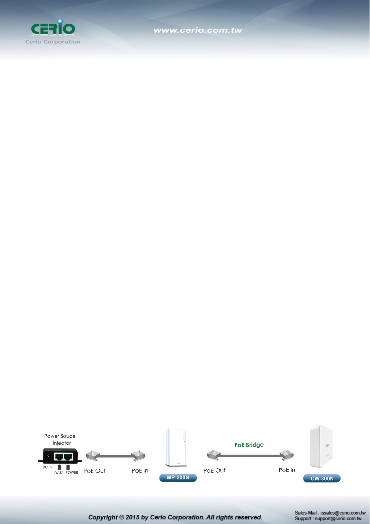
Smart of PoE Bridge Application
CERIO WP-300N eXtreme Power 11n 2.4Ghz 2x2 Wall-Plate PoE Access Point hardware is
designed with a smart PoE Bridge function. The PoE Bridge function support provides next AP
power and allows for the structure to be very convenient. The PoE Bridge supports CERIO PoE
AP,, and other Passive PoE and 802.3af PoE IPCAM solution.
Page 4

WP-300N Main Unit
x1
Power Adapter
x1
CD Manual
x1
Quick Installation Guide
x1
Warranty Card
x1
edition
USB Port
Telephone Configuration
2. Package Content
3. Hardware Specifications
Application Software
OS System Compatible
Network Standards
Conformance
Ethernet Configuration Ethernet Connector x 3 ( 802.3af/at Power over
Cerio CenOS 3.0/4.0 Software Core
Specifications
IEEE 802.11 b/g/n compliant
IEEE 802.3 / IEEE 802.3u Fast Ethernet
IEEE 802.3af/at Power over Ethernet
IEEE 802.11i Preauth (PMKSA Cache )
IEEE 802.11Q VLAN
IEEE802.11f IAPP
IEEE802.11e WMM
Ethernet PoE in and PoE Bridge LAN Port and LAN
Port )
USB A Type : Only for Power Charger
LED Indicators Power LED x 1,
RJ-11 Pass Through In x1 connector , Out x1 connector
Ethernet LED x 3 (ETH PoE in x1 / ETH1 LAN1
/ETH2LAN2)
WiFi LED x1
Wireless Specifications
Page 5
IEEE802.11n : 300Mbps (Tx), 300Mbps (Rx)
2.457 ~ 2.472 GHz (France)
Channel Spacing
IEEE802.11b/g/n : 20/40MHz
Media Access Protocol
CSMA / CA with ACK
(64-QAM,16-QAM,QPSK,BPSK)
802.11b/g/n : 11 for FCC,14 for Japan,13 for Europe, 2 for
Transmit Power Variation
Receiver Sensitivity
Environmental & Mechanical Characteristics
Operating Temperature
Storage Temperature
Operating Humidity
Storage Humidity
Antenna
Form Factor
System Power Consumption
Input Power
Dimensions ( W x H x D )
Data Transfer Rate
IEEE802.11b : 1 / 2 / 5.5 / 11Mbps (auto sensing)
IEEE801.11g : 6/ 9/ 12/ 18/ 24/ 36/ 48/ 54Mbps (auto
sensing)
Frequency Range 2.412 ~ 2.462GHz (USA)
2.412 ~ 2.484GHz (Japan)
2.412 ~ 2.472GHz (Europe ETSI)
2.457 ~ 2.462 GHz (Spain)
Modulation Method
IEEE 802.11b: DSSS (DBPK,DQPSK,CCK)
IEEE 802.11g/n: OFDM
Operating Channels
Spain,
4 for France
Max : 27 ± 1 dBm
Max : -92 dBm
-10 °C ~ 55 °C
-20 °C ~ 65°C
10% - 90% Non-Condensing
10% - 90% Non-Condensing
Build in 2x2 Smart Omni Directional Antenna
Support Wall Plate and Wall Mount
9 Watt Max.
Power Supply 110 – 220V AC Power;12 VDC,1A Input.
Supports Power Over Ethernet ( POE 48~57V voltage)
Integragted IEEE 802.3af /at Power over Ethernet (PoE)
AC to DC 12 VDC, 1 A
TBD
Page 6
Unit Weight
Certifications
TBD
CE ,FCC,NCC、BSMI 、ROHS compliant
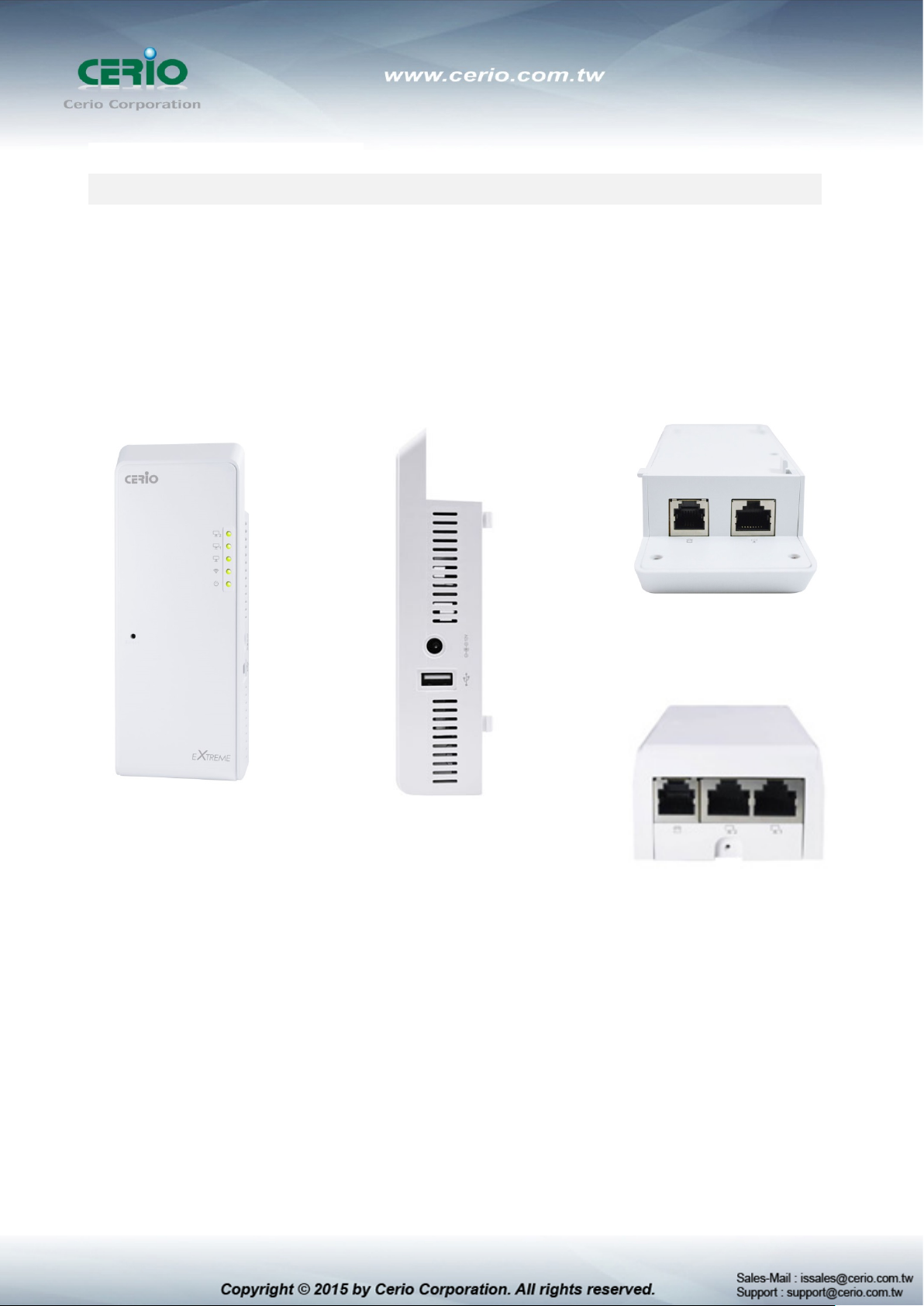
4. Product Outward Appearance
Front Side Panel
Side Panel
Top Panel
Bottom Panel
Page 7
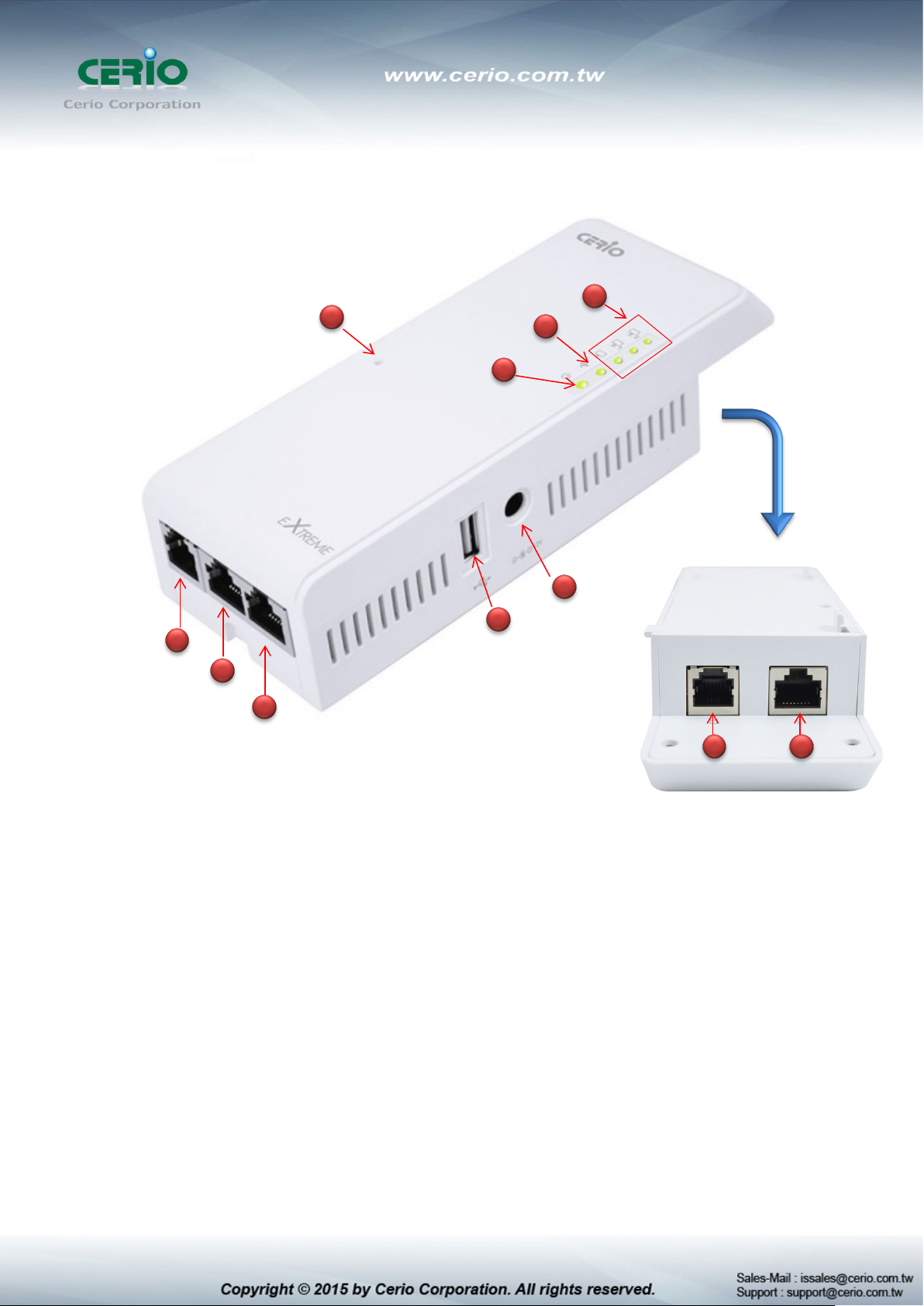
5. Product Outward Appearance and Function Description
4
2
1
3
8
7
6
5
9
10 11
(1) The three LED indicator of LAN Port.
(2) The LED indicator of Wi-Fi.
(3) The LED indicator of Power.
(4) Reset default button. (Hold the reset button for more than 15 sec. to system default configuration)
(5) The Ethernet(RJ-45) port for LAN1
(6) The Ethernet (RJ-45) port for LAN2 and PoE Bridge function.
(7) The RJ-11 port for Phone line out.
(8) Power DC in.
(9) USB Charging port
(10) The RJ-11 Phone line-in port.
(11) The Ethernet (RJ-45) port for LAN0( PoE in)
Page 8
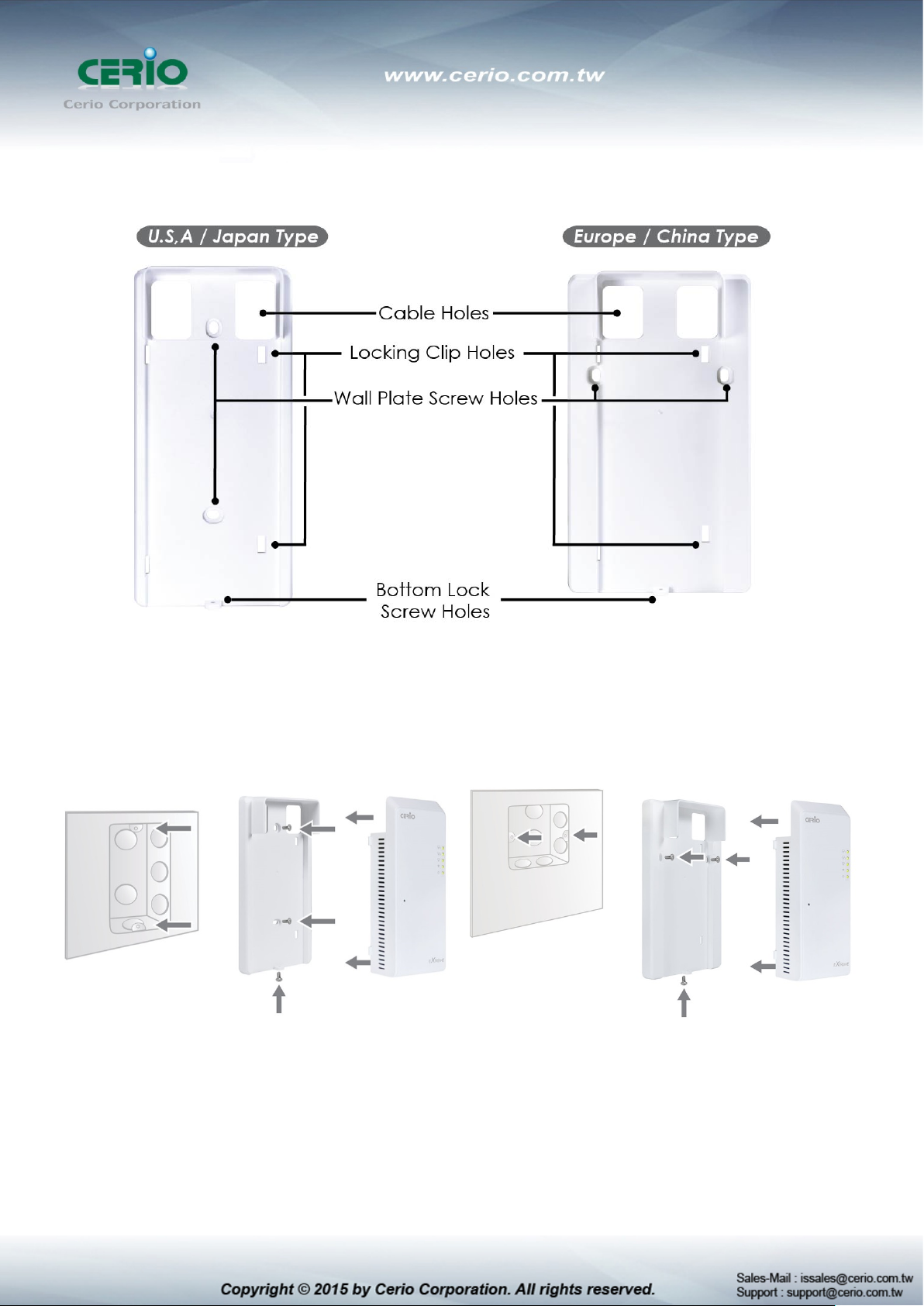
6. Product with Bracket Variations (U.S.A Type & E.U Type)
7. Wall Plate and Device Installation
U.S.A Type Outlet Box
(Used in U.S.A, Japan, & Taiwan)
E.U Type Outlet Box
(Used in Europe & China)
Page 9
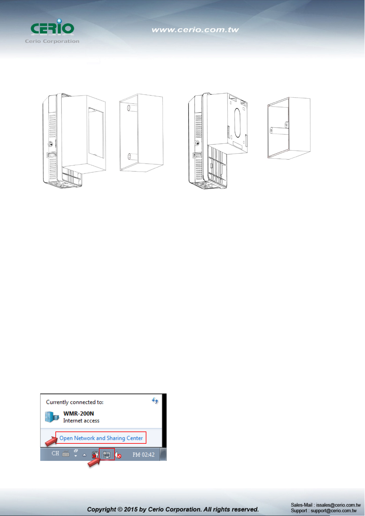
8. Product and Outlet Box Interlocking Schematics
U.S.A Type Outlet Box
(Used in U.S.A, Japan, & Taiwan)
E.U Type Outlet Box
(Used in Europe & China)
9. Software Configuration
Example of Segment: (Windows 7)
IP Segment Set-up for Administrator's PC/NB
Set the IP segment of the administrator's computer to be in the same range as WP-300N for accessing
the system. Do not duplicate the IP Address used here with IP Address of WP-300N or any other device
within the network.
Step 1 :
Please click on the computer icon in the bottom right window, and click “Open Network and Sharing
Center”
Page 10
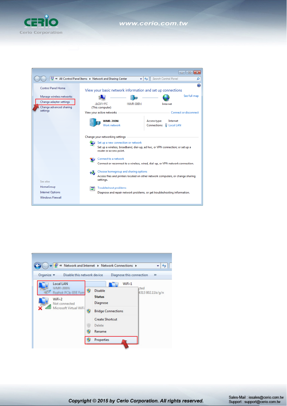
Step 2 :
In the Network and Sharing Center page, Please click on the left side of “Change adapter setting”
button
Step 3 :
In “Change adapter setting” Page. Please find Local LAN and Click the right button on the mouse and
Click “Properties”
Page 11
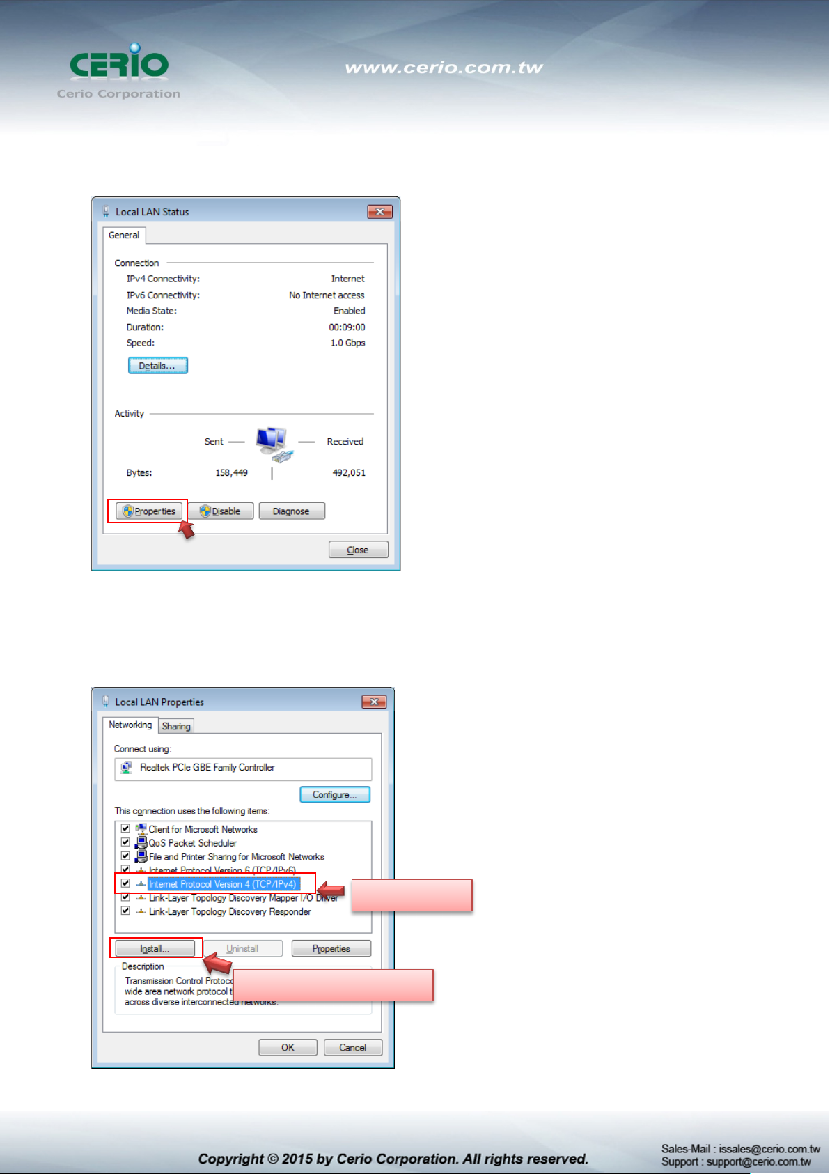
Double click
Or click Install button
Step 4 :
In “Properties” page, please Click “Properties” button to TCP/IP setting
Step 5 :
In Properties page to setting IP address, please find “Internet Protocol Version 4 (TCP/IPv4)” and
double click or click “Install” button.
Page 12
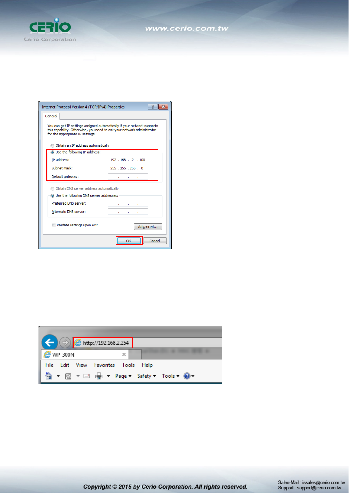
Step 6 :
Select “Use the following IP address”, and fix in IP Address : 192.168.2.#
ex. The # is any number by 1 to 253
Subnet mask : 255.255.255.0
And Click "OK" to complete the fixed computer IP setting
Step 7 :
Open Web Browser
Launch as web browser to access the web management interface of system by entering the default IP
Address, http://192.168.2.254, in the URL field, and then press Enter. Browser will pop up "login" page.
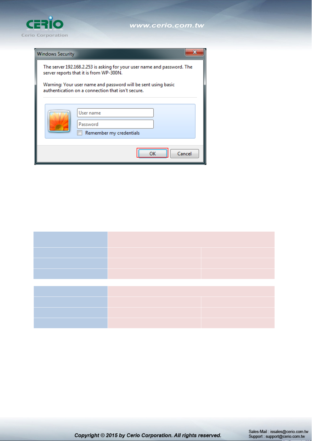
Please key in username and password into the system on WP-300N.
Page 13
By CenOS4.0 Software
AP / Client Bridge + Repeater AP mode
Default IP Address
192.168.2.254
Repeater AP mode
Default IP Address
192.168.2.254
Account
root
The system manager Login Page then appears.
Enter “root” as User name and “default” as Password, and then click “OK” to login to the system.
Login information
By CenOS3.0 Software Router / AP / WDS/Client Bridge + Repeater AP/ WISP+
Password default
Account root
Password default
Please base your Software version check to GS CenOS3.0 or NGS CenOS4.0 User’s
Manual
 Loading...