

Page 1

®
Owner’s Manual and
Installation Instructions
CENTURION 3500
Air-cooled, Prepackaged
Automatic Standby Generator
• Model: 04791-0
3.4kW LP
Not intended for use as Primary Power in place of utility
or in life-support applications.
!
!
This manual should
remain with the unit.
DEADLY EXHAUST FUMES. OUTDOOR INTALLATION ONLY!!
DANGER
Page 2

Generac®Power Systems, Inc.
INTRODUCTION
Thank you for purchasing this model of the CENTURION product line by Generac Power Systems Inc.
This model is designed and manufactured to supply
electrical power for residences.
READ THIS MANUAL THOROUGHLY
If any portion of this manual is misunderstood, contact the nearest Generac Authorized Service Dealer
for starting, operating and servicing procedures.
Throughout this publication, and on tags and decals
affixed to the generator, DANGER, WARNING, CAUTION and NOTE blocks are used to alert personnel to
special instructions about a particular operation that
may be hazardous if performed incorrectly or carelessly. Observe them carefully. Their definitions are
as follows:
After this heading, read instructions that, if not
strictly complied with, will result in serious personal injury, including death, as well as property damage.
After this heading, read instructions that, if not
strictly complied with, may result in serious personal injury or property damage.
After this heading, read instructions that, if not
strictly complied with, could result in damage to
equipment and/or property.
NOTE:
After this heading, read explanatory statements
that require special emphasis.
These safety warnings cannot eliminate the hazards
that they indicate. Common sense and strict compliance with the special instructions while performing
the service are essential to preventing accidents.
Four commonly used safety symbols accompany the
DANGER, WARNING and CAUTION blocks. The type
of information each indicates follows:
This symbol points out important safety information that, if not followed, could endanger
personal safety and/or property of others.
This symbol points out potential explosion hazard.
This symbol points out potential fire hazard.
This symbol points out potential electrical
shock hazard.
CONTENTS
This manual contains pertinent owner’s information,
including warranty, electrical diagrams, exploded
views and lists of repair parts for generator model
numbers 04791-0. In addition, the latter portion of
this manual contains information necessary for the
proper installation of these generators.
OPERATION AND MAINTENANCE
It is the owner's responsibility to perform all safety
checks, to make sure that all maintenance for safe
operation is performed promptly, and to have the
equipment checked periodically by a Generac
Authorized Service Dealer. Normal maintenance service and replacement of parts are the responsibility of
the owner and, as such, are not considered defects in
materials or workmanship within the terms of the
warranty. Individual operating habits and usage contribute to the need for maintenance service.
Proper maintenance and care of the generator ensure
a minimum number of problems and keep operating
expenses at a minimum.
HOW TO OBTAIN SERVICE
When your generator requires servicing or repairs,
simply contact a Generac Authorized Service Dealer
for assistance. Service technicians are factory trained
and are capable of handling all service needs.
When contacting a Generac Authorized Service
Dealer about parts and service, always supply the
complete model number and serial number of the
unit as given on its data decal, which is located on the
generator.
Model No. ____________ Serial No. ______________
AUTHORIZED SERVICE
DEALER LOCATION
To locate the nearest GENERAC AUTHORIZED
SERVICE DEALER, please call this number:
1-800-333-1322
ONLY DEALER LOCATION INFORMATION
CAN BE OBTAINED AT THIS NUMBER.
DANGER
!
Page 3

Table of Contents
CENTURION 3500 Home Standby Generator
Generac®Power Systems, Inc. 1
Part I – Owner’s Manual
Introduction ........................................Inside Front Cover
Read This Manual Thoroughly ....................................IFC
Contents ......................................................................IFC
Operation and Maintenance ........................................IFC
How to Obtain Service..................................................IFC
Authorized Service Dealer Locator Number ................IFC
Safety Rules ........................................................................2
Section 1 - General Information ....................................4
1.1 Generator Identification ........................................4
1.2 Unpacking/Inspection ............................................5
1.3 Safety ....................................................................6
1.4 Protection Systems................................................6
1.5 Location ................................................................6
1.6 Specifications ........................................................6
Section 2 - Operation........................................................7
2.1 Generator Control Panel........................................7
2.2 Before Starting the Engine ....................................8
2.3 Battery Connection................................................8
2.4 The Battery ..........................................................9
2.5 Before Initial Start-up............................................9
2.6 Stopping the Generator ......................................10
2.7 Applying Loads to Generator ..............................10
2.8 Do Not Overload the Generator ..........................10
2.9 Protection Systems..............................................10
2.10 Additional Information ........................................12
Section 3 - Maintenance ................................................12
3.1 Checking the Engine Oil Level ............................12
3.2 Changing the Engine Oil and/or Oil Filter ..........12
3.3 Maintaining the Engine Air Cleaner ....................13
3.4 Clean Air Intake ..................................................14
3.5 Checking the Engine Spark Plug ........................14
3.6 Clean Spark Arrestor ..........................................14
3.7 Cleaning the Generator ......................................15
3.8 Battery Maintenance............................................15
3.9 Exercising the Generator ....................................16
3.10 Out of Service Procedure ....................................16
3.11 Adjusting Valve Clearance ..................................17
3.12 Generator Service Interval ..................................17
Part II – Installation Instructions
Safety Rules ......................................................................19
Section 1 - General Information ..................................21
1.1 Tools Required....................................................21
1.2 Items That Must Be Purchased ..........................21
1.3 Plan the Location of the Generator......................21
Section 2 - Installation ..................................................22
2.1 Site Preparation and Generator Placement ........22
2.2 Power Cord Installation ......................................22
2.3 Mount Power Transfer Motor ..............................23
2.4 Install Propane Tanks ........................................23
2.5 Set System for Automatic Operation ..................25
2.6 How to Keep the Regulator Operating
Efficiently & Safely ..............................................25
2.7 What is Regulator Freeze Up?..............................25
Appendix 1 - Troubleshooting ......................................26
Appendix 2 - Notes..........................................................27
Appendix 3 - Electrical Data ........................................30
Appendix 4 - Exploded Views and Parts Lists..........34
Appendix 5 - Warranty ..................................................48
Page 4
2 Generac®Power Systems, Inc.
Study these SAFETY RULES carefully before
installing, operating or servicing this equipment.
Become familiar with this manual and with the unit.
The generator can operate safely, efficiently and reliably only if it is properly installed, operated and
maintained. Many accidents are caused by failing to
follow simple and fundamental rules or precautions.
Generac cannot possibly anticipate every possibility
that might involve a hazard. The warnings in this
manual, and on tags and decals affixed to the unit,
are, therefore, not all-inclusive. If using a procedure,
work method or operating technique Generac does
not specifically recommend, satisfy yourself that it is
safe for others. Also make sure the procedure, work
method or operating technique chosen does not render the generator unsafe.
Despite the safe design of this generator, operating this equipment imprudently, neglecting
its maintenance or being careless can cause
possible injury or death. Permit only responsible and capable persons to operate or maintain
this equipment.
Potentially lethal voltages are generated by
these machines. Ensure all steps are taken to
render the machine safe before attempting to
work on the generator.
Parts of the generator are rotating and/or hot
during operation. Exercise care near running
generators.
GEN
ERAL HAZARDS
• For safety reasons, Generac recommends that the
maintenance of this equipment is carried out by a
Generac Authorized Service Dealer.
• The generator engine releases DEADLY carbon
monoxide gas through its exhaust system. This
dangerous gas, if breathed in sufficient concentrations, can cause unconsciousness or even death.
Never operate the generator inside any garage or
other enclosed area. DO NOT OPERATE THE
GENERATOR IF THE EXHAUST SYSTEM IS
LEAKING OR HAS BEEN DAMAGED. SYMPTOMS
OF CARBON MONOXIDE POISONING ARE (a)
inability to think coherently, (b) nausea, (c) vomiting, (d) twitching muscles, (e) throbbing temples,
(f) dizziness, (g) headaches, (h) weakness, and (i)
sleepiness. IF EXPERIENCING ANY OF THESE
SYMPTOMS, MOVE INTO FRESH AIR IMMEDIATELY. IF SYMPTOMS PERSIST, GET MEDICAL
HELP. Shut down the generator and do not operate
it until it has been inspected and repaired.
• The engine exhaust fumes contain carbon monox-
ide, which can be DEADLY. This dangerous gas, if
breathed in sufficient concentrations, can cause
unconsciousness or even death. This exhaust system must be installed properly, in strict compliance with applicable codes and standards.
Following installation, do nothing that might render the system unsafe or in noncompliance with
such codes and standards. Never operate this
equipment with a leaking or defective exhaust system.
• Keep hands, feet, clothing, etc., away from drive
belts, fans, and other moving or hot parts. Never
remove any drive belt or fan guard while the unit is
operating.
• Adequate, unobstructed flow of cooling and venti-
lating air is critical to correct generator operation
and is required to expel toxic fumes and fuel vapors
from the generator. Without sufficient cooling airflow, the engine/generator overheats, which causes
serious damage to the generator. Do not alter the
installation or permit even partial blockage of ventilation provisions, as this can seriously affect safe
operation of the generator.
!
!
!
Safety Rules
CENTURION 3500 Home Standby Generator
SAVE THESE INSTRUCTIONS – The manufacturer suggests that these rules for safe
operation be copied and posted in potential hazard areas of the recreational vehicle.
Safety should be stressed to all operators and potential operators of this equipment.
!
!
The engine exhaust from this product
contains chemicals known to the state
of California to cause cancer, birth
defects or other reproductive harm.
WARNING:
This product contains or emits chemicals
known to the state of California to cause
cancer, birth defects or other reproductive harm.
WARNING:
SAVE THESE INSTRUCTIONS – This manual contains important instructions that should be
followed during installation and maintenance of the generator and batteries.
!
!
!
!
!
!
DANGER
!
Page 5
Generac®Power Systems, Inc. 3
• When working on this equipment, remain alert at
all times. Never work on the equipment when
physically or mentally fatigued.
• Inspect the generator regularly, and contact the
nearest Generac Authorized Service Dealer immediately for parts needing repair or replacement.
• Before performing any maintenance on the generator, disconnect its battery cables to prevent accidental start up. Disconnect the cable from the battery post indicated by a NEGATIVE, NEG or (–)
first. Reconnect that cable last.
• Never use the generator or any of its parts as a
step. Stepping on the unit can stress and break
parts, and may result in dangerous operating conditions from leaking exhaust gases, fuel leakage,
oil leakage, etc.
ELECTRICAL HAZARDS
• The generator covered by this manual produces
dangerous electrical voltages and can cause fatal
electrical shock. Avoid contact with bare wires, terminals, connections, etc., while the unit is running.
Ensure all appropriate covers, guards and barriers
are in place before operating the generator. If work
must be done around an operating unit, stand on
an insulated, dry surface to reduce shock hazard.
• Do not handle any kind of electrical device while
standing in water, while barefoot, or while hands
or feet are wet. DANGEROUS ELECTRICAL
SHOCK MAY RESULT.
• During installation, have the generator properly
grounded (bonded) by means of an approved
bonding conductor. DO NOT disconnect the bonding conductor. DO NOT reconnect the bonding
conductor to any generator part that might be
removed or disassembled during routine maintenance. If the grounding conductor must be
replaced, use only a flexible conductor that is of
No. 12 American Wire Gauge (AWG) copper wire
minimum.
• In case of accident caused by electric shock, immediately shut down the source of electrical power. If
this is not possible, attempt to free the victim from
the live conductor. AVOID DIRECT CONTACT
WITH THE VICTIM. Use a nonconducting implement, such as a dry rope or board, to free the victim from the live conductor. If the victim is unconscious, apply first aid and get immediate medical
help.
• Never wear jewelry when working on this equipment. Jewelry can conduct electricity resulting in
electric shock, or may get caught in moving components causing injury.
FIRE HAZARDS
• For fire safety, the generator must be installed and
maintained properly. Installation always must
comply with applicable codes, standards, laws and
regulations. Adhere strictly to local, state and
national electrical and building codes. Comply
with regulations the Occupational Safety and
Health Administration (OSHA) has established.
Also, ensure that the generator is installed in
accordance with the manufacturer’s instructions
and recommendations. Following proper installation, do nothing that might alter a safe installation
and render the unit in noncompliance with the
aforementioned codes, standards, laws and regulations.
EXP
LOSION HAZ
ARDS
• Do not smoke around the generator. Wipe up any oil
spills immediately. Ensure that no combustible
materials are left in the generator compartment, or
on or near the generator, as FIRE or EXPLOSION
may result. Keep the area surrounding the generator clean and free from debris.
Safety Rules
CENTURION 3500 Home Standby Generator
Page 6
4 Generac®Power Systems, Inc.
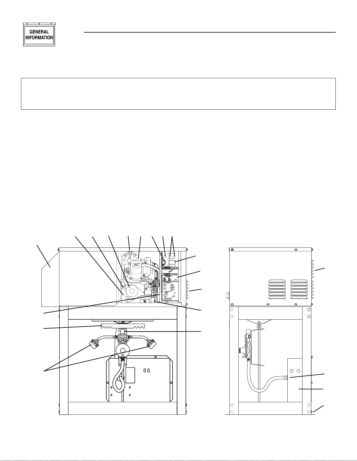
1. Generator Air Intake
2. Engine AUTO/OFF/MANUAL Switch
3. Fuse
4. LED Indicator
5. Demand Regulator (Inside Compartment)
6. Change-over Regulator
7. Circuit Breakers
8. Starter Contactor
9. Fuel Inlet
10. Tank Hook-ups.
11. Battery (In Compartment)
12. Oil Filter
13. Oil Drain (From Underside)
14. Oil Dipstick
15. Air Filter (Behind Access Panel)
16. Oil Fill
17. Spark Plug
18. Tank Hold Down Brace
19. Exhaust Hood
(Tailpipe and Spark Arrestor Inside)
20. Ground Lug
21. Data Decal (Located inside compartment)
Section 1 – General Information
CENTURION 3500 Home Standby Generator
Please record the following information from the generator DATA DECAL or information decal.
1. Model Number ____________________ 2. Serial Number __________________
3. kW Rating__________________________ 4. Rated Voltage __________________
072347
QT
RATO
R
T
OR
R
USE
.5A
1.1 GENERATOR IDENTIFICATION
Model: 004700-0 — QUIETPACT 40G
21
18
10
19
13
14, 16
12
8
17
4
3
7
2
15
1
9
6
5
1
11
20
GENERAT
F
POWE
7
PUSH TO RESE
R POWE
0.8L/0.84
Page 7
Generac®Power Systems, Inc. 5
Section 1 – General Information
CENTURION 3500 Home Standby Generator
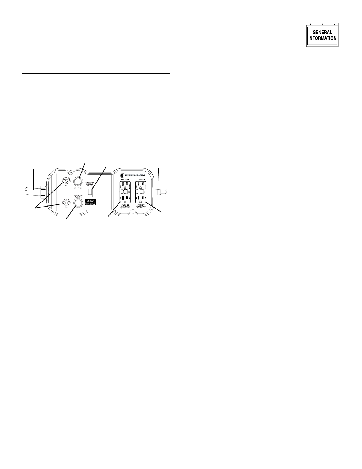
1.1.1 POWER TRANSFER MONITOR
The Power Transfer Monitor controls the automatic
function of the Centurion 3500 generator set. It’s six
foot utility sensing cord monitors the utility line when
it is plugged into a standard household 120 volt outlet.
NOTE:
Automatic start-up upon utility power outage will
not occur if six foot sensing cord is not plugged
into a utility powered 120 volt outlet.
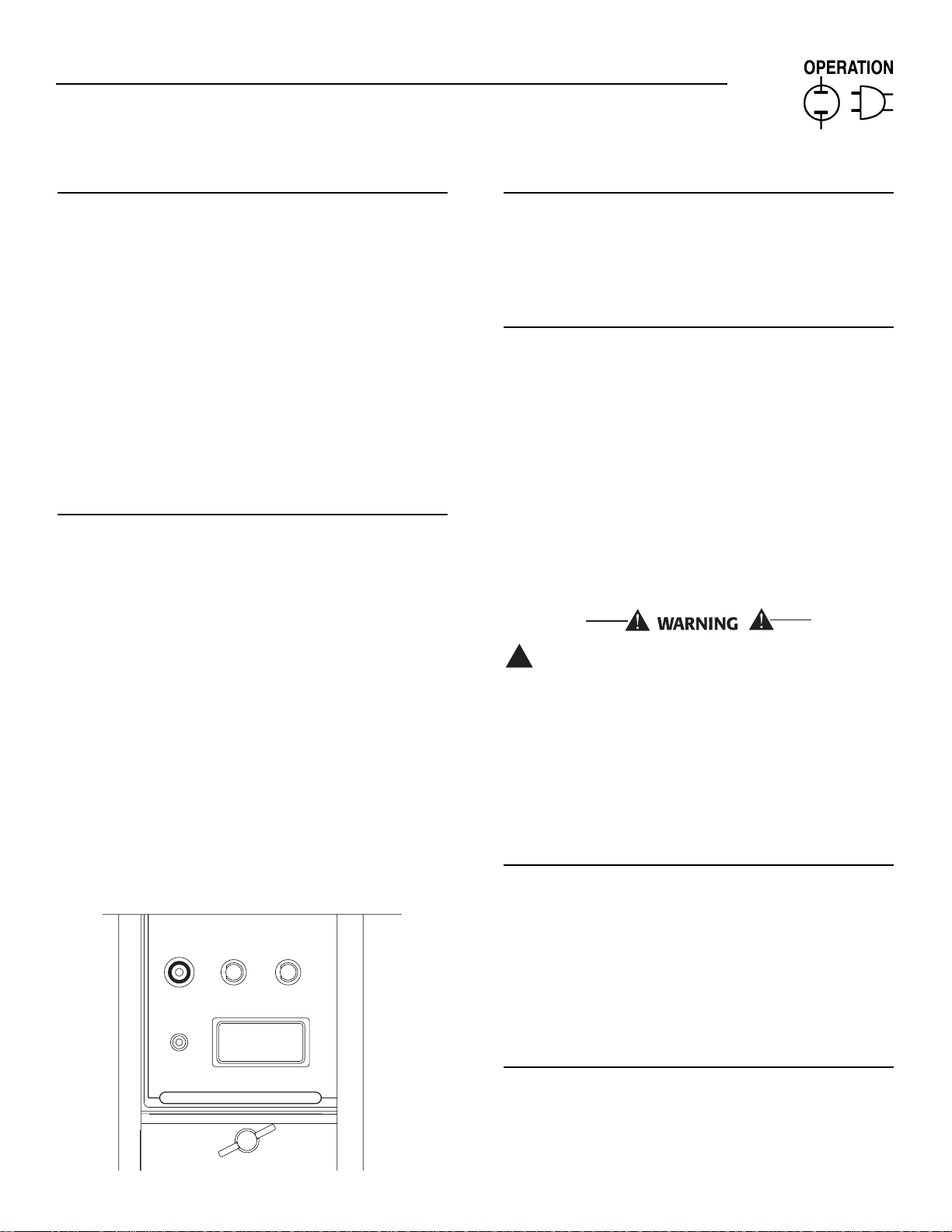
Figure 1.2 — Power Transfer Monitor
1. Generator Power Conduit (15 foot)
2. Circuit Breaker Reset (2)
3. Generator Power Indicator Lamp
4. Utility Power Indicator Lamp
5. Generator Exercise Switch
6. Switched GFCI Outlet
7. Standby GFCI Outlet
8. Utility Sensing Cord (6 foot)
1.1.1.1 Generator Power Conduit
This conduit connects the Power Transfer Monitor,
which is located inside the home, to the generator
outside.
1.1.1.2 Circuit Breaker Reset
If the generator should experience an overload for
any reason, the circuit breaker(s) will trip. The circuit breaker reset(s) should be pushed to reset after
overload condition has been corrected.
1.1.1.3 Generator Power Indicator Lamp
This lamp will illuminate when the generator has
started and is supplying power to the Power Transfer
Monitor’s GFCI outlets.
1.1.1.4 Utility Power Indicator Lamp
This lamp will be illuminated when normal utility
power is available.
1.1.1.5 Generator Exercise Switch
This switch activates the exercise cycle of the generator. Make sure the combined loads do not exceed generator capacity.
1.1.1.6 Switched GFCI Outlet
This outlet is powered by the utility and by the generator. When utility power is present is acts as another normal household outlet. When the generator is
supplying power this outlet is then being supplied
with power from the generator.
NOTE:
There will be a momentary “No Power” period
between the time of utility failure and the generator start up.
1.1.1.7 Standby GFCI Outlet
This outlet is ONLY powered by the generator. Use it
for additional items during a utility power outage
when the generator is providing backup electricity for
the home.
1.1.1.8 Utility Sensing Cord
When plugged into a standard grounded 120 volt outlet this cord allows the Power Transfer Monitor to
sense the utility line condition and react to a power
outage.
1.2 UNPACKING/INSPECTION
After unpacking, carefully inspect the contents for
damage.
• This standby generator set has been factory supplied with a weather protective enclosure that is
intended for outdoor installation only.
• This standby generator set is prepackaged with an
automatic power transfer monitor. The power
transfer monitor is prewired with 15 foot conduit
and six foot utility sensing cord with plug. The
Power Transfer Monitor is for indoor installation
only.
If any loss or damage is noted at time of delivery, have
the person(s) making the delivery note all damage on
the freight bill or affix his or her signature under the
consignor’s memo of loss or damage.
If loss or damage is found after delivery, separate the
damaged materials and contact the carrier for claim
procedures if applicable.
Use this generator to supply electrical power for
operating 120-volt, single-phase, 60 Hertz, AC electrical loads. These loads can require up to 3,400
watts (3.4 kW) of power, but cannot exceed 28.3 AC
amperes of current at 120 volts.
✧ ✧ ✧ ✧
✧
✧
✧ ✧
1
2
3
4
5
6
7
8
Page 8
6 Generac®Power Systems, Inc.
Section 1 – General Information
CENTURION 3500 Home Standby Generator
Do not overload the generator. Some installations may require that electrical loads be alternated to avoid overloading. Applying excessively high electrical loads may damage the
generator and may shorten its life. Add up the
rated watts of all electrical lighting, appliance,
tool and motor loads the generator will power
at one time. This total should not be greater
than the wattage capacity of the generator. If
an electrical device nameplate gives only volts
and amps, multiply volts times amps to obtain
watts (volts x amps = watts). Some electric
motors require more watts of power (or amps
of current) for starting than for continuous
operation.
1.3 SAFETY
Before attempting to use the generator set, carefully
read the “Safety Rules” section of this manual.
Comply strictly with these rules to prevent accidents
and damage to equipment and/or property. We suggest copying and posting the “Safety Rules” in potential hazard near the generator. Stress safety to all
operators and potential operators of this equipment.
1.4 PROTECTION SYSTEMS
Unlike an automobile engine, the generator may have
to run for long periods of time with no operator present to monitor engine conditions. For that reason,
the engine is equipped with the following systems
that protect it against potentially damaging conditions:
1. Overcrank
2. Overspeed
3. Low Oil Pressure Sensor
4. High Temperature Sensor
5. Underspeed
There is an LED readout on the control panel to noti-
fy personnel that one of these faults has occurred.
Detail of of the protection systems can be found in
Section 2.9.
1.5 LOCATION
Install the generator set, in its protective enclosure,
outdoors, where adequate cooling and ventilating air
is always available. Consider these factors:
• Install the unit where air inlet and outlet openings
will not become obstructed by leaves, grass, snow,
etc. If prevailing winds will cause blowing or drifting, consider using a windbreak to protect the unit.
• Install the generator on high ground where water
levels will not rise and endanger it.
• Allow sufficient room on all sides of the generator
for maintenance and servicing. A good rule is to
allow three feet of space on all sides.
• Where strong prevailing winds blow from one
direction, face the generator air inlet openings to
the prevailing winds.
1.6 SPECIFICATIONS
1.6.1 FUEL REQUIREMENTS AND RECOMMENDATIONS
With LP gas, use only the LP vapor withdrawal system. This type of system uses the vapors formed
above the liquid fuel in the storage tank.
Recommended fuel should have a BTU content of at
least 2,520 BTU's per cubic foot. Ask the LP fuel supplier for the BTU content of the fuel.
This generator has been designed for a specific type
of tank. Acceptable tank types are DOT-4BA240 and
DOT-4BW240. Any deviation in tank type may not
allow the tank to fit in the LP enclosure.
Gaseous fuels such as liquid propane (LP) gas
are highly explosive. Even the slightest spark
can ignite such fuels and cause an explosion.
No leakage of fuel is permitted. LP gas, which
is heavier than air tends to settle in low areas.
1.6.2 FUEL CONSUMPTION
Fuel consumption is in gal/hr.
1.6.3 ENGINE OIL REQUIREMENTS
Use only high quality detergent oil rated with
American Petroleum Institute (API) Service
Classification SF, SG or SH. The recommended oil
weights include the following:
• During summer months: SAE 30. An acceptable
substitute is SAE 10W-30.
• During winter months: SAE 5W-30. DO NOT USE
SAE 10-W40.
Crankcase and oil filter capacity is approximately
800 mL or .84 U.S. quarts. Do NOT use special additives. See Sections 3.1 and 3.2 for oil level check and
fill procedures.
!
!
Model 1/2 Load Full Load
Centurion 3500 0.55 0.73
(04791-0)
DANGER
Page 9
Generac®Power Systems, Inc. 7
Section 2 – Operation
CENTURION 3500 Home Standby Generator
1.6.4 ENGINE
Type of Engine ............................GN-220, Single-cylinder
Cooling Method..................................................Air-cooled
Rated Horsepower ..................................7.8 @ 4,200 rpm
Displacement............................................................220cc
Cylinder Block ....................Aluminum w/Cast Iron Sleeve
Type of Governor ........................Mechanical, Fixed Speed
Air Cleaner ..................Paper Element w/Foam Precleaner
Starter ................................................12-volt DC Electric
Ignition System ................Solid-state w/Flywheel Magneto
Recommended Spark Plug
Champion ..........................................................RC12YC
AC ..........................................................................R45S
Fram Autolite ..............................................................65
Spark Plug Gap ..................................0.03. inch (76 mm)
Recommended Minimum
Battery ......................................235cc Amperes @ 32°F/
195cc Amperes @ 0° F
1.6.5 GENERATOR
Rated Maximum Continuous
AC Output (LP)................................3,400 Watts (3.4kW)
Rated Voltage ................................................120 Volts AC
Rated Maximum Continuous
AC Current (LP) ........................................28.3 Amperes
Phase ......................................................................Single
Rotor RPM................................................................3,600
Number of Rotor Poles ....................................................2
Engine RPM..............................................................3,600
Rated AC Frequency ................................................60 Hz
Battery Charge Voltage ....................................14 Volts DC
Battery Charge Current ..........................2 Amperes (max)
Length ..................................................843 mm (33.2 in.)
Width ....................................................504 mm (19.8 in.)
Height ......................................................966 mm (38 in.)
Weight ......................................................90 kg (275 lbs.)
2.1 GENERATOR CONTROL PANEL
The following features are mounted on the generator
control panel (Figure 2.1):
Figure 2.1 — Generator Control Panel
2.1.1 SHUT DOWN INDICATOR
This LED will flash a specific number of times to indicate a specific failure. Shutdowns and their failure
codes follow in Section 2.9, Protection Systems. These
codes can also be referenced on the decal located on
the air filter cover, located below the control panel.
2.1.2 AUTO/OFF/MANUAL SWITCH
2.1.2.1 Auto Position
Selecting this switch position activates fully automatic system operation. It also allows the user the ability to start and exercise the generator from the remote
Power Transfer Monitor.
2.1.2.2 Off Position
This switch position shuts down the engine. This
position also prevents the engine from starting.
2.1.2.3 Manual Position
Selecting this switch position will crank and start the
engine. Transfer to standby power will not occur
unless there is a utility failure.
With the switch set to AUTO, the engine may
crank and start at any time without warning.
Such automatic starting normally occurs when
utility power source voltage drops below a preset level or during the normal exercise cycle. To
prevent possible injury that might be caused by
such sudden starts, always set the switch to
OFF and remove the fuse before working on or
around the generator or transfer switch. Then,
place a “Do Not Operate” tag on the generator
panel and on the transfer switch.
2.1.3 FUSE
The generator panel's 7.5 amp fuse protects the DC
control circuit against overload. The fuse is wired in
series with the battery output lead to the panel. If the
fuse element has melted open, the engine cannot
crank or start. The same fuse also protects the battery charge circuit against overload. If the fuse element has melted open, battery charging will not be
possible. Replace the fuse using only an identical 7.5
amp fuse.
2.1.4 MAIN BREAKERS
The main breakers protect the generator’s AC output
circuit against overload and provide a method of
turning OFF the generator’s 120-volt AC output to the
Power Transfer Monitor’s outlets. The CENTURION
3500 has two (2) 15-amp breakers.
!
✧ ✧ ✧
FUSE
7.5A
SHUT
DOWN
GENERATOR
POWER
GREEN BAR INDICATES TRIP
PUSH TO RESET
15 15
PULL TO DISCONNECT
GENERATOR POWER
INDICATOR
SEE CHART
BELOW FOR
DETAILS
CONTROL CENTER
AUTO
OFF
MAN.
Page 10
8 Generac®Power Systems, Inc.
Section 2 – Operation
CENTURION 3500 Home Standby Generator
2.2 BEFORE STARTING THE ENGINE
NOTE:
Instructions and information in this manual
assume the generator has been properly installed
and connected.
2.2.1 ENGINE LUBRICATION
Have the engine crankcase properly serviced with the
recommended oil before starting. Refer to Section
1.6.2 and Sections 3.1 and 3.2, for oil servicing procedures and recommendations.
Any attempt to crank or start the engine before
it has been properly serviced with the recommended oil may result in an engine failure.
2.2.2 FUEL SUPPLY
The engine must have an adequate supply of proper
fuel to operate. Before starting it, check that sufficient
fuel is available.
2.2.3 COOLING AND VENTILATING AIR
Air inlet and outlet openings in the generator compartment must be open and unobstructed for continued proper operation. Without sufficient cooling and
ventilating airflow, the engine/generator overheats,
which causes it to shut down and may damage the
generator.
2.2.4 ENGINE EXHAUST GAS
Before starting the generator engine, be sure there is
no way for exhaust gases to endanger people or animals. Close windows, doors near the generator that,
if open, might permit exhaust gases to do so.
The generator engine releases DEADLY carbon
monoxide gas through its exhaust system. This
dangerous gas, if breathed in sufficient concentrations, can cause unconsciousness or even
death. Never operate the generator set inside
any enclosed area. make sure THE EXHAUST
SYSTEM IS not LEAKING AND HAS NOT BEEN
DAMAGED. SYMPTOMS OF CARBON MONOXIDE POISONING ARE (a) inability to think coherently, (b) nausea, (c) vomiting, (d) twitching
muscles, (e) throbbing temples, (f) dizziness, (g)
headaches, (h) weakness, and (i) sleepiness. IF
EXPERIENCING ANY OF THESE SYMPTOMS,
MOVE INTO FRESH AIR IMMEDIATELY. IF SYMPTOMS PERSIST, GET MEDICAL HELP. Shut down
the generator and do not operate it until it has
been inspected and repaired.
2.3 BATTERY CONNECTION
Before connecting the battery, complete the following
steps:
1. Set the generator's AUTO/OFF/MANUAL switch to
OFF.
2. Make sure the Power Transfer Monitor’s sensing
cord (6 foot) is not plugged into an electrical outlet.
If the AUTO/OFF/MANUAL switch is not set to
its OFF position, the generator can crank and
start as soon as the battery cables are connected. If the utility power supply is not disabled
by unplugging the 6 foot sensing cord from
electrical outlet, sparking can occur at the battery posts and cause an explosion.
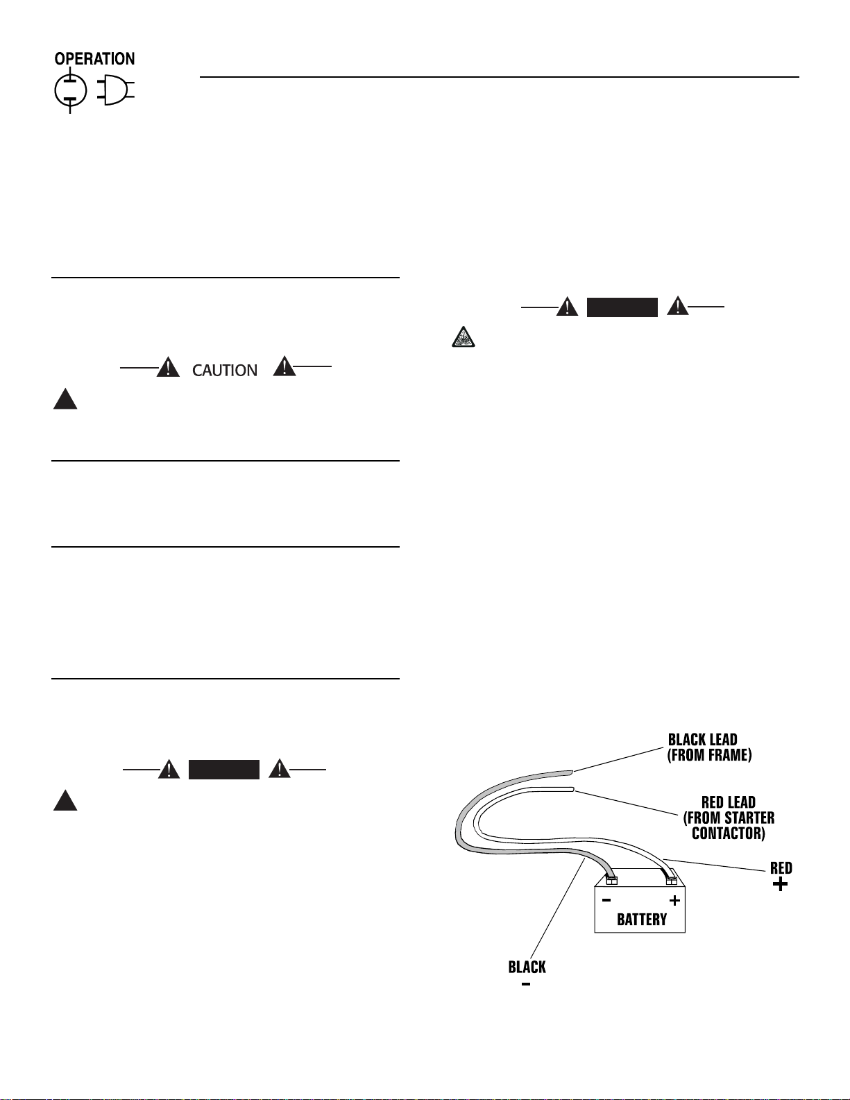
Battery cables were factory connected at the generator (Figure 2.2). Connect the cables to the battery
posts using the hardware supplied in the manual bag
as follows:
3. Slide the red battery terminal boot over the battery cable, then connect the cable (from the
starter contactor) to the battery post indicated by
a positive, POS or (+).
4. Connect the black battery cable (from frame
ground) and the two green grounding wires (from
the control panel) to the battery post indicated by
a negative, NEG or (-).
NOTE:
Damage will result if battery connections are made
in reverse.
Figure 2.2 — Battery Cable Connections
!
DANGER
DANGER
!
Page 11
Generac®Power Systems, Inc. 9
Section 2 – Operation
CENTURION 3500 Home Standby Generator
2.4 THE BATTERY
Servicing of the battery is to be performed or supervised by personnel knowledgeable of batteries and
the required precautions. Keep unauthorized personnel away from batteries.
When replacing the battery, use the following type of
battery, Group U1 12-volt battery with a rating of 235
cold-cranking amps at 0° C (32° F); 195 cold-cranking amps at -17.8º C (0º F) minimum. When using a
maintenance-free battery, it is not necessary to check
the specific gravity or electrolyte level. Have these
procedures performed at the intervals specified in
the “Service Schedule.” A negative ground system is
used. Battery connections are shown on the wiring
diagrams. Make sure the battery is correctly connected and terminals are tight. Observe battery polarity
when connecting the battery to the generator set.
Do not dispose of the battery in a fire. The battery is capable of exploding.
A battery presents a risk of electrical shock and
high short circuit current. The following precautions are to be observed when working on batteries:
• Remove watches, rings or other metal objects;
• Use tools with insulated handles;
• Wear rubber gloves and boots;
• Do not lay tools or metal parts on top of the battery; and
• Disconnect charging source prior to connecting or
disconnecting battery terminals.
Do not open or mutilate the battery. Released
electrolyte has been known to be harmful to
the skin and eyes, and to be toxic.
The electrolyte is a dilute sulfuric acid that is
harmful to the skin and eyes. It is electrically
conductive and corrosive. The following procedures are to be observed:
• Wear full eye protection and protective clothing;
• Where electrolyte contacts the skin, wash it off
immediately with water;
• Where electrolyte contacts the eyes, flush thoroughly and immediately with water and seek medical attention; and
• Spilled electrolyte is to be washed down with an
acid neutralizing agent. A common practice is to
use a solution of one pound (500 grams) bicarbonate of soda to one gallon (4 liters) or water. The
bicarbonate of soda solution is to be added until
the evidence of reaction (foaming) as ceased. The
resulting liquid is to be flushed with water and
the area dried.
Lead-acid batteries present a risk of fire
because they generate hydrogen gas. The following procedures are to be followed:
• DO NOT SMOKE when near the battery;
• DO NOT cause flame or spark in battery area; and
• Discharge static electricity from body before touching the battery by first touching a grounded metal
surface.
Be sure the AUTO/OFF/MANUAL switch is set to
the OFF position before connecting the battery
cables. If the switch is set to AUTO or MANUAL,
the generator can crank and start as soon as
the battery cables are connected.
2.5 BEFORE INITIAL START-UP
Before starting the generator, complete the following:
1. Set the generator's main circuit breakers (located
in generator’s control panel) to their OFF or
OPEN positions by pulling the reset buttons outward. A visible GREEN stripe should appear.
2. Set the generator's AUTO/OFF/MANUAL Switch to
the OFF position.
3. Turn OFF all loads connected to the Power
Transfer Monitor through the GFCI outlets.
4. Check the engine crankcase oil level and, if nec-
essary, fill to the dipstick full mark with the recommended oil. Do not fill above the oil FULL
mark.
5. Check the fuel supply. Both tanks should be full.
6. The changeover valve tank indicator should be
GREEN.
2.5.1 INITIAL START UP - PURGING THE
FUEL SYSTEM
To purge the air that is in the lines of the fuel
system, perform the following:
1. Connect the LP tanks and open both tank valves.
Make sure that the selector lever on the
changeover regulator is pointing at one of the two
tanks. Also verify that the Full/Empty indicator on
top of the changeover regulator is GREEN.
2. Set the generator's main circuit breakers to their
OFF or OPEN positions by pulling the reset buttons outward. A visible Green stripe should
appear.
3. Move the AUTO/OFF/MANUAL switch to the MANUAL position.
!
DANGER
!
!
Page 12

10 Generac®Power Systems, Inc.
Section 2 – Operation
CENTURION 3500 Home Standby Generator
4. The engine will crank and attempt to start for
approximately 15 seconds. Due to the air that will
be in the fuel lines, the engine may not start during the first 15 second cranking cycle. If the
engine does not start during the first crank cycle,
it will rest for approximately 15 seconds and then
attempt to start again. The complete starting
cycle is as follows:
• 15 seconds ON
• 15 seconds OFF
• 7 seconds ON
• 7 seconds OFF
• Repeat for 45 seconds, Approximately 90 seconds total. The engine should start during the
first or second attempt.
5. If the unit does not start during this crank cycle,
verify that all fuel connections are tight and that
the tank valves are open. Turn the
AUTO/OFF/MANUAL switch to the OFF position,
wait 3-5 seconds, then repeat steps 3-4.
6. If the engine does not start after repeating steps
3-4, contact the nearest Generac Authorized
Service Dealer for assistance.
2.5.2 CHECKING AUTOMATIC OPERATION
To check the system for proper automatic operation,
proceed as follows:
1. Set the generator's main circuit breakers to their
OFF or OPEN positions by pulling the reset buttons outward. A visible GREEN stripe should
appear.
2. Check that the AUTO/OFF/MANUAL switch is set
to OFF.
3. Turn ON the utility power supply to the Power
Transfer Monitor by plugging the 6-foot sensing
cord into a standard household outlet.
4. Set the generator's main circuit breakers to their
ON or CLOSED position by pressing in the reset
buttons.
5. Set the AUTO/OFF/MANUAL switch to AUTO, the
system is now ready for automatic operation.
6. Turn off the utility power supply to the Power
Transfer Monitor by unplugging it’s 6-foot power
cord from the household outlet.
Once the Power Transfer Monitor senses the utility
source power is turned OFF, and after an approximate five second delay, the engine should crank and
start. After starting, the Power Transfer Monitor
should connect load circuits to the standby or generator side. Both sets of GFCI outlets on the Power
Transfer Monitor should have power. Confirm transfer of power by depressing the test buttons on both
GFCI outlets. Each one should trip and the indicator
will illuminate.
With the generator running and power is available to
the GFCI outlets, turn the utility power supply ON
once again by plugging the six foot power cord into a
standard household outlet. The following should
occur.
• The Power Transfer Monitor should sense the
return of utility power and transfer the loads
plugged into the SWITCHED GFCI back to the utility source. Any loads connected to the STANDBY
GFCI will remain powered by the generator until it
shuts down. In the event of a real outage, these
loads would be reconnected to the utility.
• About two minutes after re-transfer, the engine
should shut down. However, if the engine was not
run for it's minimum run time based on starting
time, it may run for a longer period of time before
shutting down. (20 minutes max.)
• The minimum run time is pre-programmed into
the generator micro processor and is provided to
ensure that the starting battery is fully charged
before the engine shuts down. The minimum run
time is based on the time it takes for the engine to
crank and start. For every one second of cranking,
the generator will run for 1.5 minutes.
2.6 STOPPING THE GENERATOR
1. Turn OFF all electrical loads using the means
provided (such as the generator fs main circuit
breakers).
2. Let generator run at no-load for a few minutes, to
stabilize internal engine generator temperatures.
3. Place the AUTO/OFF/MANUAL switch in its OFF
position.
2.7 APPLYING LOADS TO GENERATOR
When applying electrical loads to the generator,
observe these guidelines:
Before applying electrical loads, let the generator
stabilize and warm up for a minute or two.
DO NOT overload the generator.
2.8 DO NOT OVERLOAD THE
GENERATOR
Read the rated wattage/amperage capacity of the generator in GENERATOR data, (see Section 1.6.5).
Applying electrical loads in excess of the unit’s rated
capacity will cause the engine/generator to automatically shut down.
To avoid overloading, add up the wattage of all connected electrical lighting, appliance, tool and motor
loads. This total should not be greater than the generator’s rated wattage capacity.
Page 13
Generac®Power Systems, Inc. 11
Section 3 – Maintenance
CENTURION 3500 Home Standby Generator
• Most lighting, appliance, tool and motor loads indicate their required watts on their nameplate or
data plate. For light bulbs, simply note the wattage
rating of the bulb.
• If a load does not show its rated wattage, multiply
that load’s rated VOLTS times AMPS to obtain
WATTS.
• Induction type motors (such as those that run a
furnace fan, refrigerator, window air conditioner,
etc.) need about 2-1/2 time more watts of power for
starting than for running (for a few seconds during
motor starting). Be sure to allow for this when connecting electrical loads to the generator. First, figure the watts needed to start electric motors in the
system. To that figure, add the running wattages of
other items that will be operated by the generator.
• Do not apply heavy electrical loads for the first two
or three hours of operation.
2.9 PROTECTION SYSTEMS
2.9.1 OVERCRANK — 2 FLASHES OF LED
This feature prevents the generator from damaging
itself when it continually attempts to start and another problem, such as no fuel supply, prevents it from
starting. The unit will crank and rest for a preset time
limit. Then, it will stop cranking, and the LED will
light indicating an overcrank failure. The AUTO/OFF/
MANUAL switch will need to be set to OFF and then
back to AUTO to reset the generator control board.
NOTE:
If the fault is not repaired, the overcrank feature
will continue to activate.
2.9.1.1 Approximate Crank Cycle Times
• 15 seconds ON
• 15 seconds OFF
• 7 seconds ON
• 7 seconds OFF
• Repeat for 45 seconds
Approximately 90 seconds total
2.9.2 OVERSPEED — 3 FLASHES OF LED
This feature protects the generator from damage by
shutting it down if it happens to run faster than the
preset limit. This protection also prevents the generator from supplying an output that could potentially
damage appliances connected to the generator circuit. Please reference Appendix 1, Troubleshooting, if
this fault occurs.
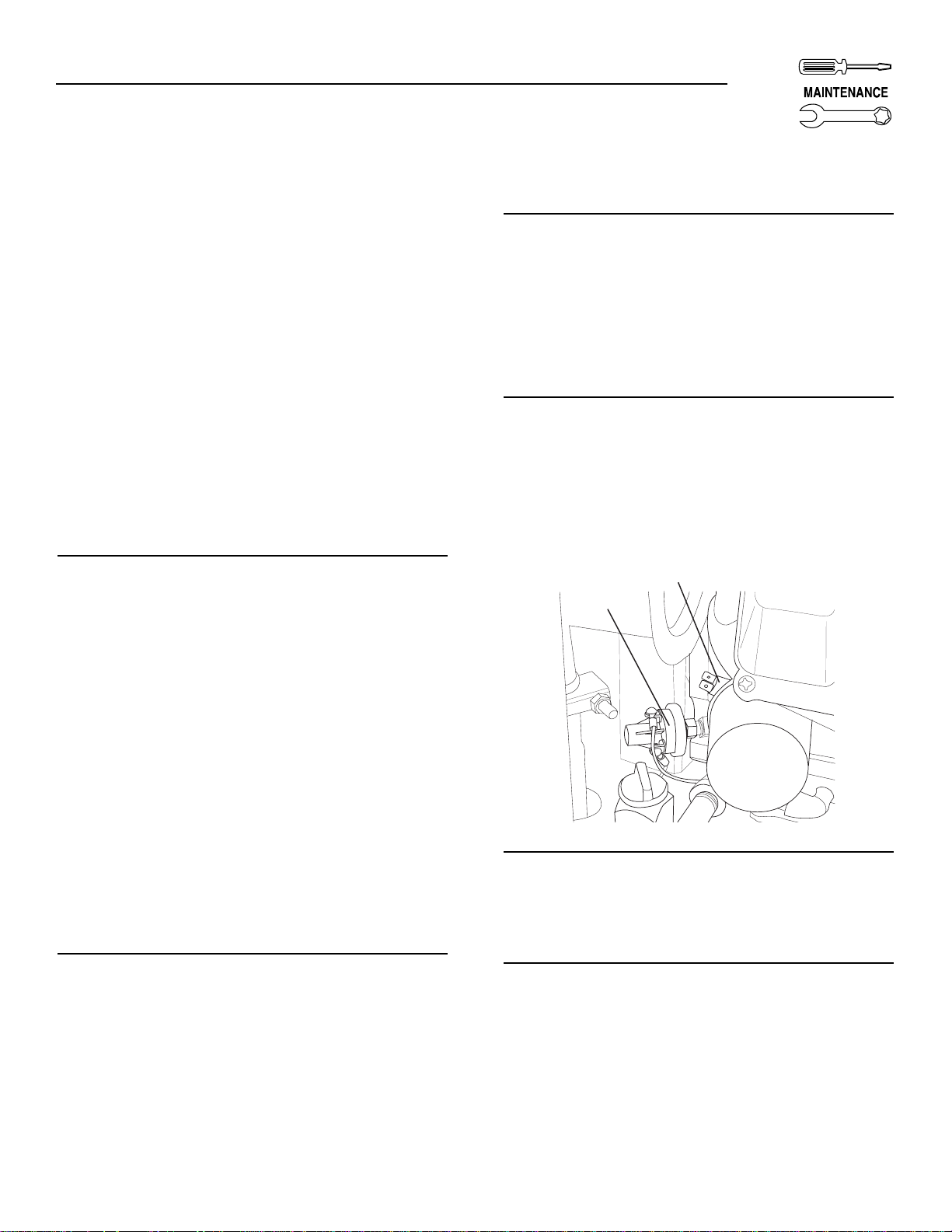
2.3.3 LOW OIL PRESSURE SWITCH —
4 FLASHES OF LED
This switch (Figure 2.2) has normally closed (N.C.)
contacts that are held open by engine oil pressure
during cranking and operating. Should oil pressure
drop below a preset level, switch contacts close, and
the engine automatically shuts down. The unit should
not be restarted until oil is added. Please reference
Appendix 1, Troubleshooting, if this fault occurs.
2.9.4 HIGH TEMPERATURE SWITCH —
5 FLASHES OF LED
This switch (Figure 2.2), which has normally open
(N.O.) contacts, is mounted near the oil filter. The
contacts close if the temperature should exceed
approximately 284° F (140° C), initiating an engine
shutdown. Please reference Appendix 1,
Troubleshooting, if this fault occurs.
Figure 2.3 — Low Oil Pressure and High
Temperature Switches
2.9.5 UNDERSPEED — 6 FLASHES OF LED
This feature protects the generator from damage by
shutting down if it happens to run slower than the
preset limit. Please reference Appendix 1,
Troubleshooting, if this fault occurs.
2.9.6 FIELD BOOST
The Controller Circuit Board houses a field boost
diode and resistor. These two components are part of
a “field boost” circuit (Figure 2.4). During engine
cranking only, a positive DC (battery) voltage is delivered through the diode, resistor, brushes and slip
rings, to the generator rotor. Application of this voltage to the rotor “flashes the field” whenever it is started. Flashing of the field each time the generator starts
makes sure that a sufficiently strong magnetic field is
available to produce “pickup” voltage in the stator
windings.
✧
High Temperature Switch
Low Oil Pressure
Switch
Page 14

12 Generac®Power Systems, Inc.
Section 3 – Maintenance
CENTURION 3500 Home Standby Generator
Figure 2.4 — Field Boost Circuit
2.9.7 OVERVOLTAGE PROTECTION
A solid-state voltage regulator (Figure 2.5) controls
the generator’s AC output voltage. This regulator supplies an excitation current to the rotor. By regulating
the rotor’s excitation current, the strength of its magnetic field is regulated and, in turn, the voltage delivered to connected electrical loads is controlled. When
the AC frequency is 60 Hertz, voltage is regulated at
120 volts (voltage-to-frequency ratio is 2-to-1).
Figure 2.5 — Solid State Voltage Regulator
The voltage regulator also incorporates a “voltage
surge protection circuit”. This circuit prevents troublesome surges in the generator AC output voltage.
Voltage surge is a common cause of damage to electronic equipment.
2.10 ADDITIONAL INFORMATION
2.10.1 BREAK-IN PERIOD
The first few hours of operation is the break-in period for the generator. Properly breaking in the generator is essential to minimize fuel consumption and
provide maximum engine performance. During this
break-in period, follow this procedure:
• Run the unit at different electrical loads by plugging items into the Power Transfer Monitor’s outlets. This will help seat the engine piston rings
properly.
• Check the engine oil level frequently. Add oil if
needed. It is normal for the generator engine to
consume more oil than is normal until the piston
rings have properly seated.
• After operating the unit for the break-in period,
complete the tasks recommended under Section
2.10.2.
2.10.2 POST BREAK-IN CHECK-UP
After the break-in period, the owner should perform
the following maintenance items:
• Change the engine crankcase oil and oil filter.
• Check the oil level.
• Inspect the cooling and ventilation openings.
• Check the engine ignition system.
• Inspect the entire electrical system.
• Inspect the engine exhaust system.
2.10.3 ATTENTION REQUIRED AFTER
SUBMERSION
If the generator has been submerged in water, it
MUST NOT be started and operated. Following any
submersion in water, have a Generac/Centurion
Authorized Service Dealer thoroughly clean and dry
the generator.
2.10.4 OPERATION IN HIGH GRASS OR
BRUSH
Never operate the generator while it is in contact with
high grass, weeds, brush, leaves or any other combustible substance. Such materials can ignite and
burn from the heat of the exhaust system. The generator exhaust system becomes extremely hot during
operation and remains hot for a long time after it has
shut down.
2.10.5 EFFECTS OF MOISTURE AND DIRT
Keep the generator set as clean and dry as possible.
Protect the unit against excessive dust, dirt, corrosive
vapors, etc. Permitting dirt and moisture to accumulate on generator windings will have an adverse effect
on the insulation resistance of those windings.
When moisture is allowed to remain in contact with
windings, some of the moisture will be retained in
voids and cracks in the insulation. This causes a
reduced insulation resistance and will eventually
cause problems. Dirt will make the problem worse,
since dirt tends to hold moisture in contact with
windings. Salt (as from sea air) also will worsen the
problem since it tends to absorb moisture from the
air. Salt and moisture, when combined, form an electrical conductor which is detrimental to the generator.
CONTROLLER
CIRCUIT
BOARD
4
O
GRND
F
CLOSEST TO
BEARING
FIELD
Page 15
Section 3 – Maintenance
CENTURION 3500 Home Standby Generator
3.1 CHECKING THE ENGINE OIL
LEVEL
For oil capacities and requirements, see “Engine Oil
Requirements,” Section 1.6.3. Check the engine
crankcase oil level weekly. To check the engine oil
level, proceed as follows (see Figure 3.1):
1. Remove the oil fill/dipstick cap and wipe the dip-
stick dry with a clean, lint-free cloth.
2. Install and tighten the oil fill/dipstick cap; then,
remove it again. The oil level should be at the dipstick “Full” mark.
3. If necessary, slowly add oil until it reaches the
dipstick “FULL” mark. DO NOT FILL ABOVE
THE “FULL” MARK.
Never operate the engine with the oil level
below the “Add” mark on the dipstick. Doing
this could damage the engine.
4. Install and tighten the oil fill/dipstick cap before
operating the engine.
3.2 CHANGING THE ENGINE OIL
AND/OR OIL FILTER
• Change the engine oil after the break-in period,
(see Section 2.10.1). Thereafter, change oil every
twelve months. Change the oil more frequently if
unit operates during extended power outages of
several days at a time, in dusty conditions or at
high ambient temperatures.
• Change the engine oil filter after the break-in peri-
od, and every twelve months thereafter.
To change the oil and/or oil filter, proceed as follows
(see Figure 3.1):
1. Run the engine until it is thoroughly warmed up
(at least five minutes) then shut OFF the engine.
2. Immediately after the engine shuts OFF, remove
the plug from the tube with a 5/16” allen wrench
and drain the oil into a suitable container.
Loosening the oil fill/dipstick cap will allow the
crankcase to drain faster.
3. After the oil has drained, replace the plug onto
the end of the oil drain tube.
4. With the oil drained, remove the old oil filter by
turning it counterclockwise. Place a towel underneath to catch excess oil.
5. Apply a light coating of clean engine oil to the gasket of the new filter. Fill the filter until saturated
with clean oil.
6. Screw the new filter on by hand until its gasket
lightly contacts the oil filter adapter. Then, tighten the filter an additional 3/4 to one turn.
7. Remove the oil fill/dipstick cap and wipe the dipstick dry with a clean, lint-free cloth. This will be
used later to check the oil level.
8. Slowly add the proper type and amount of recommended oil (see Section 1.6.3). Periodically
use the dipstick to check the oil level and continue to fill the crankcase until the oil reaches the
dipstick “Full” mark. DO NOT FILL ABOVE THE
“FULL” MARK.
9. Install and tighten the oil fill/dipstick cap before
operating the engine.
10. Start the engine and check for leaks.
NOTE:
Check the oil level and fill to the “FULL” mark
after checking for leaks. The filter will retain some
oil.
!
Generac®Power Systems, Inc. 13
Figure 3.1 – Oil Maintenance Features
Dipstick & Oil Fill
Oil Drain
(Underneath)
Oil Filter
GENERATOR
FUSE
POWER
7.5A
GREEN BAR INDICATES TRIP
PUSH TO RESET
PULL TO DISCONNECT
GENERATOR POWER
SHUT
DOWN
INDICATOR
SEE CHART
BELOW FOR
MAN.
AUTO
OFF
DETAILS
CONTROL CENTER
SERVICEACCESS PANEL
GENERATOR SHUTDOWN
S
O
E
N
O
L
INFORMATION SYSTEM
FAULTSIGNAL
2 FLASHES =
OVERCRANK
3 FLASHES =
OVERSPEED
LOW OIL PRESSURE
4 FLASHES =
5 FLASHES =
HIGH OIL TEMP
6 FLASHES = UNDERSPEED
MAINTENANCE SCHEDULE
OIL LEVEL:
AIR FILTER:
LOCATED BEHIND PANEL
*
OIL & OIL FILTER:
SPARK PLUGS:
REPLACEMENT INFORMATION
PREFILTER P/N:
AIR FILTER P/N:
OIL FILTER P/N:
SPARK PLUG P/N:
OIL CAPACITY WITH FILTER:
TEMPERATURE
40˚F AND HIGHER
-20˚F TO 40˚F
API SERVICE CLASSIFICATION SF, SG OR SH
WHEN SERVICE OR PARTS ARE NEEDED IN
THE USA OR CANADA, CONTACT THE GENERAC
SERVICE LOCATOR AT 1-800-333-1322.
CHECK DAILY
CLEAN PREFILTER
EVERY 100 HOURS.
REPLACE ELEMENT
EVERY 250 HOURS.
CHANGE EVERY 100
HOURS. (OR ANNUALLY)
PERFORM MORE OFTEN IN DUSTY CONDITIONS
*
INSPECT & CLEAN
PLUGS EVERY 500
HOURS. REPLACE PLUGS
IF NECESSARY
SAE VISCOSITY
SAE 30 OR 10W-30
5W-30 OR 5W-20
SEE OWNERS
MANUAL
FOR FURTHER
EXPLANATION
}
*
*
*
0D4511
0D9723
070185
072347
0.8L/0.84QT
Page 16
14 Generac®Power Systems, Inc.
3.3 MAINTAINING THE ENGINE AIR
CLEANER
3.3.1 CLEANING THE FOAM PRECLEANER
Clean and re-oil the foam precleaner every six
months. Service the foam precleaner more frequently if operating the generator in extremely dusty or
dirty conditions. Use the following procedure (Figure
3.2):
Figure 3.2 — Engine Air Cleaner
1. Turn the two screws counterclockwise to loosen.
2. Remove the cover, foam precleaner and paper fil-
ter.
3. Remove the foam precleaner from the cover.
4. Wash the foam precleaner in liquid detergent and
water.
5. Wrap the foam precleaner in a clean cloth and
gently squeeze it dry.
6. Saturate the foam precleaner in clean engine oil.
Gently squeeze it in a clean cloth to remove
excess oil and to distribute oil (DO NOT TWIST).
7. Install the foam precleaner into the cover, fol-
lowed by the paper filter.
8. Install the cover, foam precleaner and paper filter.
9. Tighten the two screws to retain the filter in place.
3.3.2 CLEANING OR REPLACING THE PAPER
FILTER
Once each year or more frequently if operating in
dirty or dusty conditions, clean or replace the paper
filter. The new replacement filter must be flame retardant. Service the paper filter more frequently if operating the generator in extremely dusty or dirty conditions. Use the following procedure (Figure 3.2):
1. Follow steps 1-3 in Section 3.3.1; service the
foam precleaner if necessary.
2. Remove the paper filter.
3. Clean the air filter by tapping it gently on a solid
surface. If the filter is too dirty, replace it with a
new one. Dispose of the old filter properly.
4. Clean the air cleaner cover then reassemble following steps 7-9 in Section 3.3.1.
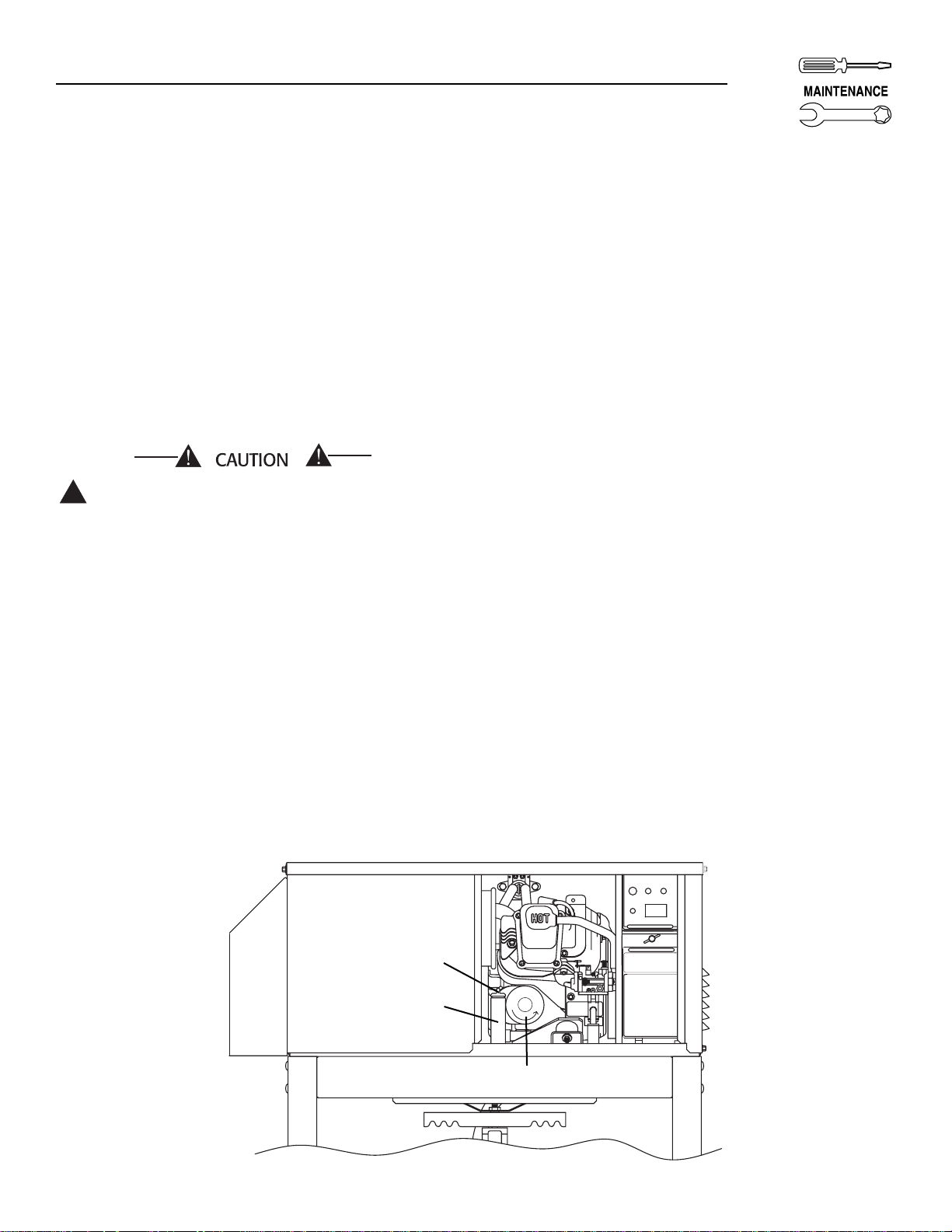
3.4 CLEAN AIR INTAKE
Clean all foreign material from the air intake (Figure
3.3) at least once every six months. Clean more often
if necessary.
Inspect the area around the generator periodically
and remove all grass, leaves, etc., from area.
Figure 3.3 — Cleaning Air Intake
3.5 CHECKING THE ENGINE SPARK
PLUG
Clean the spark plug and reset the spark plug gap
annually. Replace spark plug when the electrodes
have worn to the point where the proper gap cannot
accurately be set, or if the insulation is cracked.
1. Clean the area around the base of the spark plug
to keep dirt and debris out of the engine. Remove
the spark plug and check the condition. Replace
the spark plug if worn or if reuse is questionable.
2. Clean spark plug by scraping or washing using a
wire brush and commercial solvent. Do not blast
the spark plug to clean.
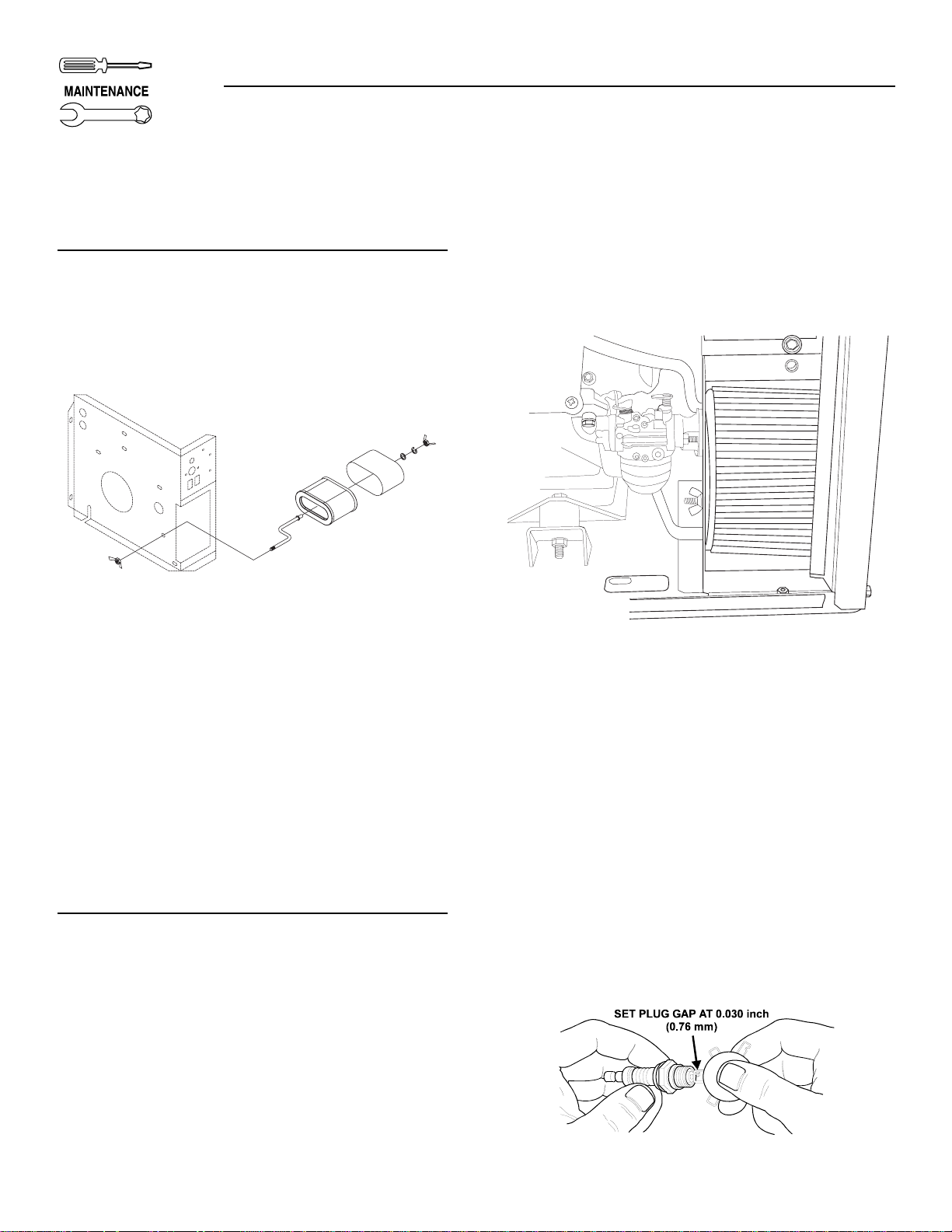
3. Check the spark plug gap using a wire feeler
gauge. Adjust the gap to 0.030 inch (0.76 mm) by
carefully bending the ground electrode (Figure
3.4).
Figure 3.4 — Setting the Spark Plug Gap
USTC
Section 3 – Maintenance
CENTURION 3500 Home Standby Generator
USTC
Page 17

Generac®Power Systems, Inc. 15
Sparking can occur if the wire terminal does
not fit firmly on the spark plug terminal end. If
necessary, re-form the wire terminal to obtain a
tight fit.
3.6 CLEAN SPARK ARRESTOR
The engine exhaust muffler has a spark arrestor
screen. Inspect and clean the screen at least once
each year.
NOTE:
If using the generator on any brush-covered or
grass-covered unimproved land, it must equipped
with a spark arrestor. The spark arrestor must be
maintained in good condition by the owner.
Clean and inspect the spark arrestor as follows:
• Remove the screen retaining bracket by removing
the screw (Figure 3.5).
• Slide the spark arrestor screen out from the
exhaust pipe.
• Inspect screen and replace if torn, perforated or
otherwise damaged. DO NOT USE a defective
screen. If screen is not damaged, clean it with commercial solvent.
• Replace the screen and the retaining bracket.
Reinstall screw.
Figure 3.5 — Spark Arrestor
3.7 CLEANING THE GENERATOR
Keep the generator set as clean and dry as possible.
Protect the unit against excessive dust, dirt, corrosive
vapors, etc. Permitting dirt and moisture to accumulate on generator enclosure reduces the effectivity of
the power-coat paint to maintain color and appearance.
Do NOT use a forceful spray of water to clean
the generator. Water will enter the generator
interior and cause problems, and may also
cause corrosion of brackets and linkage on the
generator.
3.7.1 CORROSION PROTECTION
Periodically wash and wax the generator enclosure
using automotive type products. Frequent washing is
recommended in salt water/coastal areas. Spray
engine linkage, steel brackets and fasteners with a
light oil such as WD-40®.
3.8 BATTERY MAINTENANCE
All lead-acid batteries will discharge when not in use.
The generator battery should be inspected as follows:
3.8.1 EVERY SIX MONTHS
• Inspect the battery posts and cables for tightness
and corrosion. Tighten and clean as necessary.
• Check the battery fluid level of unsealed batteries
and, if necessary, fill with Distilled Water Only. Do
not use tap water in batteries.
• Have the state of charge and condition checked.
This should be done with an automotive-type battery hydrometer if battery is not a maintenance
free type.
NOTE:
Servicing of the battery is to be performed or
supervised by personnel knowledgeable of batteries and the required precautions. Keep unauthorized personnel away from batteries. Damage will
result if the battery connections are made in
reverse.
Do not dispose of the battery in a fire. The battery is capable of exploding. Storage batteries
give off explosive hydrogen gas. This gas can
form an explosive mixture around the battery
for several hours after charging. The slightest
spark can ignite the gas and cause an explosion. Such an explosion can shatter the battery
and cause blindness or other injury. Any area
that houses a storage battery must be properly
ventilated. Do not allow smoking, open flame,
sparks, or any spark producing tools or equipment near the battery. Discharge static electricity from body before touching the battery by
first touching a grounded metal surface.
A battery presents a risk of electrical shock and
high short circuit current. The following precautions are to be observed when working on batteries:
• Remove watches, rings or other metal objects;
• Use tools with insulated handles;
• Wear rubber gloves and boots;
• Do not lay tools or metal parts on top of the battery;
!
Section 3 – Maintenance
CENTURION 3500 Home Standby Generator
!
EXHAUST PIPE
P/N 0E2138
SPARK ARRRESTOR
SCREEN P/N 089680
RETAINING
SCREW P/N 056892
DANGER
Page 18

16 Generac®Power Systems, Inc.
• Disconnect any charging source prior to connecting
or disconnecting battery terminals; and
• Do not use any jumper cables or booster battery to
crank and start the generator engine. If any battery has discharged, remove it for recharging.
Do not open or mutilate the battery. Released
electrolyte has been known to be harmful to
the skin and eyes, and to be toxic.
The electrolyte is a dilute sulfuric acid that is
harmful to the skin and eyes. It is electrically
conductive and corrosive. The following procedures are to be observed:
• Wear full eye protection and protective clothing;
• Where electrolyte contacts the skin, wash it off
immediately with water;
• Where electrolyte contacts the eyes, flush thoroughly and immediately with water and seek medical attention; and
• Spilled electrolyte is to be washed down with an
acid neutralizing agent. A common practice is to
use a solution of 1 pound (500 grams) bicarbonate
of soda to one gallon (4 liters) or water. The bicarbonate of soda solution is to be added until the
evidence of reaction (foaming) has ceased. The
resulting liquid is to be flushed with water and the
area dried.
3.9 EXERCISING THE GENERATOR
Generac recommends that this unit be exercised at
least once every seven days. This generator system
does not have an automatic exerciser or a utility fed
battery charger. The unit must be manually started
and run in order to charge the starting battery and
fully lubricate the engine. It is imperative that the battery be fully charged in the event of a power outage to
ensure that the generator starts automatically.
Couple the exercising of the generator along with
another task or activity that is done once a week.
3.9.1 TO EXERCISE THE GENERATOR:
• Make sure the AUTO/OFF/MANUAL switch located
on the generator control panel is set in the AUTO
position, and then depress and hold the EXERCISE switch located on the Power Transfer
Monitor for about ten seconds.
• The engine will start to crank and the unit will then
start.
• The unit will exercise for an amount of time that is
predetermined by the time that it takes for the generator to crank and start. The unit will exercise
approximately 1.5 minutes for every second that
the starter motor cranks during engine start-up.
The unit will run for a minimum of two minutes
and a maximum of 20 minutes based on the crank
time.
IMPORTANT: The generator power outlet located on
the Power Transfer Monitor will be "LIVE" during this
exercise cycle.
• After the generator completes its predetermined
exercise cycle, the unit will enter a cool down cycle
that will last approximately two minutes.
• The generator will then shut down, and the unit
will return to automatic operation.
3.10 OUT OF SERVICE PROCEDURE
3.10.1 REMOVAL FROM SERVICE
If unable exercise the generator every seven days, or
do not require the generator's services for an extended period of time, please prepare the generator as follows:
1. Start the engine and let it warm up.
2. Close the fuel shutoff valves on both propane
tanks and allow the unit to shut down.
3. While the engine is still warm from running,
drain the oil completely. Refill the crankcase with
SAE 10W-30 oil having API classification “For
Service SF.”
4. Attach a tag to the engine indicating the viscosity
and classification of the oil in the crankcase.
5. Remove the spark plug and pour two or three
tablespoons of clean, fresh engine oil into the
spark plug threaded openings. Reinstall and
tighten the spark plug.
6. Disconnect battery cables (negative NEG or (—)
first). Remove the battery and store it in a cool,
dry room on a wooden board. Never store the battery on any concrete or earthen floor.
7. Clean and wipe the entire generator.
3.10.2 RETURN TO SERVICE
To return the unit to service after storage, proceed as
follows:
1. Check the tag on the engine for oil viscosity and
classification. Verify that the correct recommended oil is used in the engine (see Section 1.6.3). If
necessary, drain and refill with the proper oil.
2. Check the state of the battery. Fill all cells of
unsealed batteries to the proper level with distilled water. DO NOT USE TAP WATER IN THE
BATTERY. Recharge the battery to 100 percent
state of charge, or, if defective, replace the battery.
3. Clean and wipe the entire generator.
4. Reconnect the battery (positive POS or (+) first).
Observe battery polarity. Damage may occur if the
battery is connected incorrectly.
5. Unplug any items plugged into the Power
Transfer Monitor’s GFCI outlets.
!
!
Section 3 – Maintenance
CENTURION 3500 Home Standby Generator
Page 19

Generac®Power Systems, Inc. 17
6. Start the unit by depressing and holding the
EXERCISE switch on the Power Transfer Monitor
for about ten seconds. Allow the unit to run for
exercise cycle.
7. Re-plug items needing protection back into the
Power Transfer Monitor’s switched GFCI outlet.
8. The generator is now ready for service.
3.11 ADJUSTING VALVE CLEARANCE
After the first six months, adjust the valve clearance
in the engine.
When adjusting valve clearance, the engine should be
at outdoor ambient temperature and the piston
should be at Top Dead Center (TDC) of its compression stroke (both valves closed). Correct clearance is
0.001-0.003 inch (0.03-0.07mm). Adjust valve clear-
ance as follows:
1. Loosen the rocker arm jam nut. Use an allen
wrench to turn the pivot ball stud while checking
clearance between the rocker arm and the valve
stem with a feeler gauge (Figure 3.6).
Figure 3.6 — Adjusting Valve Clearance
2. When valve clearance is correct, hold the pivot
ball stud with the allen wrench and tighten the
rocker arm jam nut with a crows foot. Tighten the
jam nut to 65-85 inch-pounds torque. After tightening the jam nut, recheck valve clearance to
make sure it did not change (Figure 3.7).
Figure 3.7 — Tightening Jam Nut
3.12 GENERATOR SERVICE INTERVAL
CENTURION 3500
Annually ................................Clean Spark Arrestor
Annually..............................Change Engine Oil/filter
Every Six Months........................Clean Air Pre-filter
Annually....................................Inspect Spark Plugs
Annually................Replace Paper Air Filter Element
As Needed ................................Replace Spark Plugs
1st Six Months
Annually ..............................Adjust Valve Clearance
Section 3 – Maintenance
CENTURION 3500 Home Standby Generator
Page 20

18 Generac®Power Systems, Inc.
PART II –
INSTALLATION
INSTRUCTIONS
ONLY QUALIFIED ELECTRICIANS OR CONTRACTORS
SHOULD ATTEMPT INSTALLATION!!
DANGER
Page 21

Generac®Power Systems, Inc. 19
IMPORTANT SAFETY INSTRUCTIONS
CENTURION 3500 Home Standby Generator
Study these SAFETY RULES carefully before
installing, operating or servicing this equipment.
Become familiar with this manual and with the unit.
The generator can operate safely, efficiently and reliably only if it is properly installed, operated and
maintained. Many accidents are caused by failing to
follow simple and fundamental rules or precautions.
Generac cannot possibly anticipate every possible
circumstance that might involve a hazard. The warnings in th is manual, and on tags and decals affixed
to the unit, are, therefore, not all-inclusive. If using a
procedure, work method or operating technique
Generac does not specifically recommend, satisfy
yourself that it is safe for others. Also make sure the
procedure, work method or operating technique that
chosen does not render the generator unsafe.
Despite the safe design of this generator, operating this equipment imprudently, neglecting
its maintenance or being careless can cause
possible injury or death. Permit only responsible and capable persons to operate or maintain
this equipment.
Potentially lethal voltages are generated by
these machines. Ensure all steps are taken to
render the machine safe before attempting to
work on the generator.
Parts of the generator are rotating and/or hot
during operation. Exercise care near running
generators.
GEN
ERAL HAZARDS
• For safety reasons, Generac recommends that the
maintenance of this equipment is carried out by a
Generac Authorized Service Dealer.
• The generator engine releases DEADLY carbon
monoxide gas through its exhaust system. This
dangerous gas, if breathed in sufficient concentrations, can cause unconsciousness or even death.
Never operate the generator inside any garage or
other enclosed area. DO NOT OPERATE THE
GENERATOR IF THE EXHAUST SYSTEM IS
LEAKING OR HAS BEEN DAMAGED. SYMPTOMS
OF CARBON MONOXIDE POISONING ARE (a)
inability to think coherently, (b) nausea, (c) vomiting, (d) twitching muscles, (e) throbbing temples,
(f) dizziness, (g) headaches, (h) weakness, and (i)
sleepiness. IF EXPERIENCING ANY OF THESE
SYMPTOMS, MOVE INTO FRESH AIR IMMEDIATELY. IF SYMPTOMS PERSIST, GET MEDICAL
HELP. Shut down the generator and do not operate
it until it has been inspected and repaired.
• The engine exhaust fumes contain carbon monoxide, which can be DEADLY. This dangerous gas, if
breathed in sufficient concentrations, can cause
unconsciousness or even death. This exhaust system must be installed properly, in strict compliance
with applicable codes and standards. Following
installation, do nothing that might render the system unsafe or in noncompliance with such codes
and standards. Never operate this equipment with
a leaking or defective exhaust system.
• Keep hands, feet, clothing, etc., away from drive
belts, fans, and other moving or hot parts. Never
remove any drive belt or fan guard while the unit is
operating.
• Adequate, unobstructed flow of cooling and ventilating air is critical to correct generator operation
and is required to expel toxic fumes and fuel
vapors from the generator. Without sufficient cooling airflow, the engine/generator overheats, which
causes serious damage to the generator. Do not
alter the installation or permit even partial blockage of ventilation provisions, as this can seriously
affect safe operation of the generator.
• When working on this equipment, remain alert at
all times. Never work on the equipment when
physically or mentally fatigued.
• Inspect the generator regularly, and contact the
nearest Generac Authorized Service Dealer immediately for parts needing repair or replacement.
• Before performing any maintenance on the generator, disconnect its battery cables to prevent accidental start up. Disconnect the cable from the battery post indicated by a NEGATIVE, NEG or (–)
first. Reconnect that cable last.
!!!
SAVE THESE INSTRUCTIONS – This manual contains important instructions that should be followed during installation and maintenance of the generator and batteries.
SAVE THESE INSTRUCTIONS – The manufacturer suggests that these rules for safe operation
be copied and posted in potential hazard areas near the generator set. Safety should be stressed
to all operators and potential operators of this equipment.
!
!
!
!
The engine exhaust from this product
contains chemicals known to the state
of California to cause cancer, birth
defects or other reproductive harm.
WARNING:
This product contains or emits chemicals
known to the state of California to cause
cancer, birth defects or other reproductive harm.
WARNING:
!
!
!
!
DANGER
!
Page 22

20 Generac®Power Systems, Inc.
IMPORTANT SAFETY INSTRUCTIONS
CENTURION 3500 Home Standby Generator
• Inspect the generator regularly, and promptly
repair or replace all worn, damaged or defective
parts using only factory-approved parts.
• Before performing any maintenance on the generator, disconnect its battery cables to prevent accidental start-up. Disconnect the cable from the battery post indicated by a NEGATIVE, NEG or (–)
first. Reconnect that cable last.
• Never use the generator or any of its parts as a
step. Stepping on the unit can stress and break
parts, and may result in dangerous operating conditions from leaking exhaust gases, fuel leakage,
oil leakage, etc.
ELECTRICAL HAZARDS
• All generators covered by this manual produce dangerous electrical voltages and can cause fatal electrical shock. Utility power delivers extremely high
and dangerous voltages to the transfer switch as
well as the standby generator. Avoid contact with
bare wires, terminals, connections, etc., on the generator as well as the transfer switch, if applicable.
Ensure all appropriate covers, guards and barriers
are in place before operating the generator. If work
must be done around an operating unit, stand on
an insulated, dry surface to reduce shock hazard.
• Do not handle any kind of electrical device while
standing in water, while barefoot, or while hands
or feet are wet. DANGEROUS ELECTRICAL
SHOCK MAY RESULT.
• If people must stand on metal or concrete while
installing, operating, servicing, adjusting or repairing this equipment, place insulative mats over a
dry wooden platform. Work on the equipment only
while standing on such insulative mats.
• The National Electrical Code (NEC), Article 250
requires the frame and external electrically conductive parts of the generator to be connected to an
approved earth ground and/or grounding rods.
This grounding will help prevent dangerous electrical shock that might be caused by a ground fault
condition in the generator set or by static electricity. Never disconnect the ground wire.
• Wire gauge sizes of electrical wiring, cables and
cord sets must be adequate to handle the maximum electrical current (ampacity) to which they
will be subjected.
• Before installing or servicing this (and related)
equipment, make sure that all power voltage supplies are positively turned off at their source.
Failure to do so will result in hazardous and possibly fatal electrical shock.
• Connecting this unit to an electrical system normally supplied by an electric utility shall be by
means of a transfer switch so as to isolate the generator electric system from the electric utility distribution system when the generator is operating.
Failure to isolate the two electric system power
sources from each other by such means will result
in damage to the generator and may also result in
injury or death to utility power workers due to
backfeed of electrical energy.
• Generators installed with an automatic transfer
switch will crank and start automatically when
NORMAL (UTILITY) source voltage is removed or
is below an acceptable preset level. To prevent
such automatic start-up and possible injury to personnel, disable the generator’s automatic start circuit (battery cables, etc.) before working on or
around the unit. Then, place a “Do Not Operate”
tag on the generator control panel and on the
transfer switch.
• In case of accident caused by electric shock,
immediately shut down the source of electrical
power. If this is not possible, attempt to free the
victim from the live conductor. AVOID DIRECT
CONTACT WITH THE VICTIM. Use a nonconducting implement, such as a dry rope or board, to
free the victim from the live conductor. If the victim
is unconscious, apply first aid and get immediate
medical help.
• Never wear jewelry when working on this equipment. Jewelry can conduct electricity resulting in
electric shock, or may get caught in moving components causing injury.
FIRE HAZARDS
• Keep a fire extinguisher near the generator at all
times. Do NOT use any carbon tetra-chloride type
extinguisher. Its fumes are toxic, and the liquid can
deteriorate wiring insulation. Keep the extinguisher properly charged and be familiar with its use.
Consult the local fire department for any questions
pertaining to fire extinguishers.
EXPLOSION HAZARDS
• Provide adequate ventilation around the generator
to prevent build-up of explosive gas.
• Do not smoke around the generator. Wipe up any
fuel or oil spills immediately. Ensure that no combustible materials are left in the generator compartment, or on or near the generator, as FIRE or
EXPLOSION may result. Keep the area surrounding the generator clean and free from debris.
• Generac generator sets may operate using one of
several types of fuels. All fuel types are potentially
FLAMMABLE and/or EXPLOSIVE and should be
handled with care. Comply with all laws regulating
the storage and handling of fuels. Inspect the unit’s
fuel system frequently and correct any leaks immediately. Fuel supply lines must be properly
installed, purged and leak tested according to
applicable fuel-gas codes before placing this equipment into service.
• Gaseous fluids such as liquid propane (LP) gas are
extremely EXPLOSIVE. LP gas is heavier than air
and settles in low areas; install leak detectors
accordingly.
Page 23

Generac®Power Systems, Inc. 21
Section 1 – General Information
CENTURION 3500 Home Standby Generator
NOTE:
THE INSTALLATION SECTION OF THIS MANUAL
SHOULD NOT BE USED EXCLUSIVELY FOR ALL
ASPECTS OF INSTALLATION AND OPERATION
OF THE CENTURION UNIT. FAMILIARIZE YOURSELF WITH ALL FEATURES AND OPERATION OF
THE UNIT TO ENSURE SAFE USE. PLEASE READ
ALL INFORMATION PRIOR TO INSTALLATION
AND OPERATION OF THE CENTURION EMERGENCY AUTOMATIC SYSTEM.
1.1 TOOLS REQUIRED
Drill, Drill Bits, Hole Saw (type and length will be
determined by the materials that need drilling and
cutting), Open-End Wrenches or Adjustable
Wrenches, Socket Wrenches or Nut Drivers, Standard
and Phillips Screwdrivers, Level, Sledge Hammer,
Channel-lock Pliers, Spade Shovel, and Safety
Goggles.
1.2 ITEMS THAT MUST BE
PURCHASED
• (2) 20 pound propane tanks. Acceptable tank types
are DOT-4BA240 and DOT-4BW240.
• Grounding rod with grounding strap.
• Crushed stone or pea gravel (approximately 8-10
cubic feet).
• Black polyfilm or other vegetation blocking fabric
(5-1/2 feet x 3-1/2 feet).
• Silicone caulk.
• Fasteners (To mount Power Transfer Monitor).
1.3 PLAN THE LOCATION OF THE
GENERATOR
Select an area outside of the home near the room that
the Power Transfer Monitor will be located. It must
be within two cords combined length (21”) of an
inside outlet.
NOTE:
Do not place the generator directly under or next
to a window.
4a
3 ft.
1
2
3
Page 24

22 Generac®Power Systems, Inc.
Section 2 – Installation
CENTURION 3500 Home Standby Generator
2.1 SITE PREPARATION AND
GENERATOR PLACEMENT
2.1.1 SITE PREPARATION
1. Clear an area 5-1/2 feet by 3-1/2 feet of grass and
vegetation to a depth of five inches. This includes
the distance the generator should be set away
from a structure (three feet) and six inches
beyond the width and length of the generator
mounting pad (30" L x 24" W).
2. Lay black poly-film to cover the area.
3. Fill the area to ground level with pea gravel or
crushed stone.
2.1.2 ATTACH GENERATOR TO MOUNTING
PAD
Place the mounting pad in the exact desired location.
Bring the generator, still attached to the shipping pallet, to the prepared area and place it along side of the
mounting pad. Remove and discard the two (2) lag
screws that hold the generator to the shipping pallet.
Using a minimum of two adults, hold the mounting
pad in place, gently slide the generator off of the shipping pallet and onto the mounting pad. Align the
holes in the generator base with the holes in the
mounting pad. Use the supplied fasteners to attach
generator to base (Figure 2.1).
Four Each: 1” long hex head cap screw, lock washer
and flat washer.
Figure 2.1 — Attach Generator To Pad
4. Drive an 8-foot grounding rod into the ground to
grade.
A. Attach one end of the grounding strap (No. 12
AWG stranded copper wire) to grounding rod
and the other end to the grounding lug (located
at rear of unit). Make sure grounding rod and
strap are not exposed above ground level. (NEC
code applies to grounding method.)
Figure 2.2 — Grounding Lug
2.2 POWER CORD INSTALLATION
2.2.1 DRILL PASS THROUGH HOLE
The power transfer monitor needs to be located in a
position that is appealing to the homeowner.
Recommended locations are underneath or inside a
kitchen or utility room cabinet, or in a basement
where access is convenient. The homeowner should
test multiple positions to find the most appealing
one. It is not recommended that the power transfer
monitor be located where water may be present, such
as under a sink.
Determine where the flexible watertight conduit
(power cord) will pass through the house from inside
to outside (Figure 2.3). When certain there is clearance on each side of the wall and within the wall,
mark the location. Drill a small pilot hole to aid location of hole saw. Drill 1-1/4 inch diameter hole
through the wall with hole saw.
Figure 2.3 — Pass Through Hole
2.2.2 FEED POWER CORD OUT TO
GENERATOR
From the room inside the home where the Power
Transfer Monitor will be located, feed the end of the
power cord through to outside of exterior wall (Figure
2.4). DO NOT connect power cord to generator at
this time.
030795 SC
"
0
6"
0
3/8"
Grounding Lug
REW HHV 5/16"-18 X 1
22129 WASHER LOCK 5/1
22145 WASHER FLAT
Page 25

Generac®Power Systems, Inc. 23
Section 2 – Installation
CENTURION 3500 Home Standby Generator
Figure 2.4 — Feed Power Cord
2.2.3 GENERATOR CONNECTION
The power cord contains five wires with spade terminals. These wires are color coded and and labeled for
accurate connection to the generator’s terminal strip.
NOTE:
Generator mode switch should be placed in the
OFF position. Generator main circuit breakers
should be placed in the OFF or OPEN position by
pulling the reset buttons outward. A visible
GREEN stripe should appear.
1. Remove the four screws that hold the cover plate
in place at rear of generator. Remove cover plate.
2. Remove lock ring from the coupler on end of
power cord. Feed wires through cover plate, Slip
lock ring over wires and reattach lock ring to coupler. Tighten lock ring securely to assure that the
coupler will not loosen during generator operation.
3. Match the wires by color or by label to the matching terminal positions on the generator. Place the
appropriate spade connectors under the matching terminal screws. (See Figure 2.5). Tighten the
the terminal screws securely to prevent arcing.
4. Align cover plate over threaded holes. Reinstall
and tighten the four screws that hold the cover
plate to back of generator compartment.
Figure 2.5 — Generator Terminal Strip
Connection
2.3 MOUNT POWER TRANSFER
MONITOR
Hold the Power Transfer Monitor in desired location
and mark the mounting holes. The mounting holes
are 1/4 inch in diameter. Drill pilot holes. Use two
fasteners which are appropriate for the area for
mounting the Power Transfer Monitor (Figure 2.6).
NOTE:
If mounting on drywall, it is suggested to use a fastener that spreads behind the hole for added rigidity. This is necessary because of the force that will
be applied when plugging in and unplugging items
from the GFCI outlets.
Figure 2.6 — Mount Power Transfer Monitor
NOTE:
DO NOT plug the six foot sensing cord into standard household outlet at this time.
2.4 INSTALL PROPANE TANKS
This generator has been designed for a specific type
of tank. Acceptable tank types are DOT-4BA240 and
DOT-4BW240. Any deviation in tank type may not
allow the tank to fit in the LP enclosure.
Slide the latches on the top of the mesh panel downward. Tilt the panel toward you and lift out The tank
hold down brace is held in place by a large wingnut.
Loosen the wingnut to allow the brace to face perpendicular to the opening of the tank enclosure.
Tilt the top of the first tank toward you so the bottom
of the tank enters the compartment first. Set the ring
on the bottom of the tank into the recessed area of
the tank tray. Place tank in upright position in the
tank compartment. Repeat this process for second
tank.
Position tanks so that the tank hold down brace can
be brought down on top of tank flanges and flanges
slip into grooved areas of brace.
17
0
N
L2
L1
RED
WHITE
BLACK
BLUE
GREEN
Page 26

24 Generac®Power Systems, Inc.
Section 2 – Installation
CENTURION 3500 Home Standby Generator
The changeover regulator needs to be placed at a
height such that the inlet hoses are located even with
or above the cylinder valves on the LP tanks. This will
prevent LP vapor from condensing in the LP
changeover regulator and possibly damaging the fuel
system.
Tighten the wingnut securely to prevent vibration
when the generator is running.
Connect the fuel lines by carefully threading the OPD
(Overflow Protection Device) valves onto the tanks.
Make sure the valve is not cross-threaded which will
cause leaking. Open the valves on both tanks and
swab connections with soapy water to detect any
leaks. Be careful not to crimp the power cord when
the power transfer monitor is in it’s final position.
If a leak is detected in the system near the green swivel connector, there is a possibility that the flare fitting
inside the tank valve has been damaged during the
tank filling process. To inspect the fitting, turn off the
tank valve and visually inspect the flare fitting to
make sure that there are no scratches, dents or mars
on the surface of the flare. If there are visible defects
in the flare fitting of the tank, a new tank must be
used.
To assure that the hose does not kink, rub against the
tanks or the enclosure, it is important to note the orientation of the valve on the tank. It should always be
pointing towards the front of the cabinet. Do not
allow the hose to kink or rub on the tank (Figure 2.7).
Figure 2.7 — Overhead View of LP Tank
On the propane tank changeover valve, move the
black selector lever to the left or to the right to designate which tank will be the primary or service cylinder (tank). That tank will supply fuel to the generator
first. When the lever is moved to a position an indicator will show green. When that tank empties during
generator operation the indicator will show red signalling the need to refill the tank. The generator will
start drawing from the reserve cylinder. The
changeover feature allows gives the benefit of uninterrupted fuel flow to the generator.
Prior to disconnecting the service cylinder, rotate the
black lever all the way over towards the reserve cylinder. (Figure 2.8). DO NOT ATTEMPT TO CHANGE
THE LP TANK WITHOUT ROTATING THIS
LEVER. The full-empty indicator will turn green and
the reserve cylinder becomes the service cylinder.
Refill and reinstall the empty cylinder to maintain
interruption free back up power.
For model 254-00, two-stage changeover regulator, failure to rotate the black lever all the
way over towards the reserve cylinder will
allow propane to leak from the disconnect pigtail. Leaking propane, if ignited, will result in a
fire that may cause property damage, bodily
injury or death. REMEMBER: NEVER disconnect
a pigtail if the indicator is RED.
IMPORTANT: Only qualified persons should install,
adjust or service LP ga regulators. If service is needed, contact a qualified LP dealer. Always make sure
cylinders are properly filled and never accept cylinders that are over filled. When replacing newly filled
cylinders to the regulator, check all connections for
leaks with an approved leak detector solution or a
mixture of non-ammonia soap and water. Never use
matches or an open flame.
NOTE:
Low pressure regulators are designed to regulate
LP vapor only.
Figure 2.8 – LP Tank Changeover Valve
Selector Lever
Full/Empty
Indicator Window
Green - Full
Red - Empty
DANGER
Page 27

Generac®Power Systems, Inc. 25
2.5 SET SYSTEM FOR AUTOMATIC
OPERATION
Make sure the valves on both of the filled propane
cylinders are open.
At this time, plug the six foot sensing cord into a standard 120V household outlet. This will allow the
Power Transfer Monitor to sense the utility power
feed. Plug desired items into the SWITCHED GFCI
outlet on the Power Transfer Monitor. This outlet is
powered when utility power is available and when the
generator is operating during a utility power outage.
Place the generator main circuit breakers to their ON
or CLOSED position by pressing in the reset buttons.
The GREEN indicator stripe should no longer be evident.
Place the generator mode switch, which is located on
the generator control panel, in the AUTO position.
The system is now set for automatic operation.
2.6 HOW TO KEEP THE REGULATOR
OPERATING EFFICIENTLY &
SAFELY
The regulator is equipped with a vent which allows
the diaphragm to “breathe”. The diaphragm of the
regulator moves down and draws air into the bonnet
of adjustment spring housing. When the diaphragm
moves up, air is expelled through the vent. In the
event that excess pressure builds up in the lower
housing or body of the regulator, a relief mechanism
vents it to the atmosphere. It is imperative to check
the vent frequently to be sure it is clean and free of
water, corrosion or obstruction, as clogging is a
potential cause of regulator malfunction. Great care
has been taken in the manufacture of the regulator
and it has been thoroughly tested and UL listed.
However, even a small piece of dirt, corrosion, pipe
dope or other foreign material which finds its way
into the regulator can result in higher than normal
pressure (high lockup) and/or loss of fuel.
If the vent does become clogged it can easily be
cleaned with a toothbrush. In addition, the regulator
should be checked periodically by a competent LP
serviceman to be sure it is properly adjusted and in
safe working condition. By following these simple
precautions, the regulator should give you years of
trouble-free service.
2.7 WHAT IS REGULATOR FREEZE UP?
A regulator will not freeze, nor will LP gas under normal atmospheric conditions. However, as the gas
passes through the regulator it expands and cools
and moisture in the gas or in the regulator may turn
to ice. This ice can build up and totally or partially
block the orifice and thus partially or totally block
the fuel supply. There are a number of things that can
be done to prevent this type of freeze up.
1. Be sure the LP cylinder is totally free of moisture
before it is filled.
2. Be sure the cylinder is not over filled. This is particularly important if you have a permanently
mounted ASME tank.
3. Keep the valves on empty cylinders closed.
4. Have the LP gas dealer purge the cylinder if freeze
up occurs.
5. Have the LP gas dealer inject methyl alcohol in
the cylinder.
Section 2 – Installation
CENTURION 3500 Home Standby Generator
Page 28

26 Generac®Power Systems, Inc.
Appendix 1 – Troubleshooting
CENTURION 3500 Home Standby Generator
TROUBLESHOOTING GUIDE
SYMPTOM CAUSE CORRECTION
The engine will not crank. 1. Fuse blown 1. Replace fuse.
2. Loose, corroded or defective 2. Tighten, clean or replace
battery cables as necessary.
3. Defective starter contactor 3. Replace contactor.
4. Defective starter motor 4. Replace starter motor.
5. Low or defective battery 5. Charge or replace battery.
OVERCRANK – 2 flashes of LED 1. No fuel to the engine. 1. Make sure that the tanks are full and
the valves are opened.
2. Crimped fuel hose or hoses. 2. Check all fuel hoses to ensure that
there is no crimping and fuel is being
allowed to flow freely.
3. Defective fuel solenoid. 3. *
4. Open #14 wire from engine 4. *
control board.
5. Defective spark plug/plug wire 5. Clean, re-gap, or replace plug/
not connected. connect plug wire.
OVERSPEED - 3 flashes of LED 1. Governor spring is disconnected. 1. Reconnect spring. Spring should be in
the second hole from the bottom
(shaft end) of the governor arm.
2. Governor spring is broken. 2. Replace spring. *
3. Governor arm or linkages are 3. *
loose or broken.
LOW OIL PRESSURE - 1. Engine oil is low. 1. Check and fill engine oil. Check
4 flashes of LED generator compartment for leaks.
2. Oil Pressure switch is defective. 2. *
3. Oil is contaminated with dirt. 3. Change oil and oil filter.
HIGH TEMPERATURE - 1. Engine oil is low. 1. Check and fill engine oil.
5 Flashes of LED 2. Air flow is restricted. 2. Check airflow openings for blockage.
3. Spark arrestor is plugged. 3. Clean or replace the spark arrestor.
4. Oil is contaminated with dirt. 4. Change oil and oil filter.
UNDERSPEED - 6 flashes of LED 1. Fuel supply is low. 1. Check and replenish fuel supply.
2. Speed adjust linkage is damaged 2. *
or control nut is loose.
The engine starts hard 1. Air cleaner plugged or damaged 1. Check, clean or replace air cleaner.
and runs rough.
2. Defective spark plug 2. Clean, re-gap or replace plug.
The engine starts, but shuts 1. Engine oil level low 1. Check oil and add oil as needed.
down immediately. 2. Defective low oil pressure switch 2. *
3. Defective high temperature switch 3. *
4. Defective engine control board 4. *
5. Overheated engine 5. Check that the airflow openings are
adequate.
The AUTO/OFF/MANUAL switch 1. Defective switch 1. *
is set to OFF, but the engine 2. AUTO/OFF/MANUAL switch 2. *
continues to run. is wired incorrectly
3. Defective engine control board 3. *
There is no AC output from 1. Main line circuit breaker(s) 1. Reset circuit breaker(s)
the generator. open to ON (or closed).
2. Generator internal failure 2. *
There is no transfer to utility. Defective transfer relay *
* Contact the nearest Generac Authorized Service Dealer for assistance.
Page 29

Generac®Power Systems, Inc. 27
Appendix 2 – Notes
CENTURION 3500 Home Standby Generator
Page 30

28 Generac®Power Systems, Inc.
Appendix 2 – Notes
CENTURION 3500 Home Standby Generator
Page 31

Generac®Power Systems, Inc. 29
Appendix 2 – Notes
CENTURION 3500 Home Standby Generator
Page 32

CK
CUSTO
D
OP
O
86
85
D
CO
OL
SM
6
SC
8A
3
0
56
85
86
8A
85
J1
3891053
6
8
8A
56
3
0
G
0
S
0
5
C
R
3
3
5
86
5
0
0
5
3
5
66766
5
85
86
85
85
86
8A
56
0
0
0
0
0
0
0
0
8A
SP
C
0
0
8
0
0
0
0
8
0
8
SW1
5
0
0
0
0
0
0
0
0
0
0
0
0
86
0
0
0
0
0
000
0
0
0
Y
D
P
T
S
A
A
A
S
OR
SC
OR
SSU
CH
D
GRD3
D
A
GFC
T
G
D
C
R
N
CB 3
R
D
E
E
CH
OR
OR
OR
OR
S
UG
.
CIC
C
R
CB 5
R
L
S
30 Generac®Power Systems, Inc.
Appendix 3 – Electrical Data
CENTURION 3500 Home Standby Generator
Wiring Diagram - Drawing No. 0E4263-A
LEGEN
BA - BRUSH ASSEMBL
CB 1 - 2A CIRCUIT BREAKER, AUTO RESET, ALT. EXCITATIO
B 2 - 15A 1 POLE CIRCUIT BREAKE
- 15A 1 POLE CIRCUIT BREAKE
B 4 - 15A 1 POLE CIRCUIT BREAKE
- 15A 1 POLE CIRCUIT BREAKE
D - DIOD
F1 - FUSE, 7.5
FS - FUEL SOLENOI
I - GROUND FAULT CIRCUIT INTERUP
RD1 - CONTROL PANEL GROUN
GRD2 - CONTROL PANEL GROUND, ISOLATE
- POWER STRIP GROUN
HTO - HIGH OIL TEMPERATURE SWIT
IC - INLINE CONNECT
IM - IGNITION MODUL
L1 - UTILITY PRESENT INDICAT
L2 - GENERATOR RUNNING INDICAT
LED - ALARM INDICAT
LOP - LOW OIL PRE
- STARTER CONTACT
M - STARTER MOT
P - SPARK PL
SR - REMOTE START RELAY, SPST, 120V COIL, 250V 5A CONTACT
OPEN = UTILITY PRESENT, CLOSED = UTILITY NOT PRESEN
SW1 - AUTO-OFF-MANUAL SWITCH, ON-OFF, 125V, 15
SW2 - POWER SWITCH, ON-OFF, 125V, 15
SW3 - EXCERCISE SWITCH, (ON)-OFF, 250V, 5
TB1 - TERMINAL STRIP, GEN. TO POWER STRI
TB2 - TERMINAL STRIP, POWER STRIP TO GEN
TB3 - TERMINAL STRIP, STATOR TO CONTROL PANE
TR - TRANSFER RELAY, SPDT, 120V COIL, 250V 20A CONTACT
RE SWIT
ENGINE WIRIN
I
HARGE
1
1
F
7
1
1
HT
1
L
1
BLA
1
1
NTR
PRINTED CIRCUIT BOAR
1
1
1
17
1
1
I
1
1
1
1
1
1
17
MER SUPPLIE
1
Page 33

Generac®Power Systems, Inc. 31
CLOSES
G
GE
OR
62
0
6
4
66
62
6
G
2
6
0
CO
OX
66
66
CB1
62
6
S
OR
000
0
0
0
0
0
0
D
3
5
D
OT
OT
5
6
5
0
0
0
0
0
0
0
0
U
Y
G
OR
SR
SW3
0
0
0
0
CB2
CB3
0
66
C
P
G
0
GFCI
GFCI
0
G
1
0
0
0
0
0
0
0
0
0
0
0
0
0
0
S
D
0
G
G
0
0
0
0
0
0
0
0
0
0
DLOAD
G
3
CB4
CB5
G
CO
OX
R
3
CUSTOMER
CO
ON
C
C
G
G
G
G
)
)
)
)
)
.
Appendix 2 – Electrical Data
CENTURION 3500 Home Standby Generator
Wiring Diagram - Drawing No. 0E4263-A
VOLTA
REGULAT
NTROL PANEL B
1
TB
6
1
1
RD
T TO BEARIN
TAT
WITCHE
LOA
H
LOA
HITE
H
CUSTOME
NNECT B
11
RD
11
RD
15 FT
POWER STRI
RED (L1
WHITE (N
BLACK (L2
BLUE (17
GREEN (0
TILIT
ENERAT
LOA
WIRIN
11
11
11
11
NNECTI
Page 34

GE
C
R
C
R
BATTERY
T
A
D
5
CO
OL
86
8
0
56
56
5
5
5
8
85
56
56
5
8
8
86
86
85
8
8
0
8A
8A
8586018A
E
CB 3
R
N
C
R
CH
E
A
OR
D
OR
0
6
62
3
66
5
0
SW1
913
0
6
8
5
J1
3
0
0
0
0
6
3
56
CB 1
5
85
86
8A
0
0
0
6
6
OR
SSU
CH
SC
OR
S
OR
A
A
S
S
D
Y
CO
OL
0
0
CB 4
CB 5
C
R
CB 5
R
32 Generac®Power Systems, Inc.
Appendix 3 – Electrical Data
CENTURION 3500 Home Standby Generator
Wiring Diagram - Drawing No. 0E6560
LEGEN
BA - BRUSH ASSEMBL
CB 1 - 2A CIRCUIT BREAKER, AUTO RESET, ALT. EXCITATIO
B 2 - 15A 1 POLE CIRCUIT BREAKE
- 15A 1 POLE CIRCUIT BREAKE
B 4 - 15A 1 POLE CIRCUIT BREAKE
- 15A 1 POLE CIRCUIT BREAKE
D - DIOD
F1 - FUSE, 7.5
FS - FUEL SOLENOI
HTO - HIGH OIL TEMPERATURE SWIT
IM - IGNITION MODUL
L1 - UTILITY PRESENT INDICAT
L2 - GENERATOR RUNNING INDICAT
LED - ALARM INDICAT
LOP - LOW OIL PRE
- STARTER CONTACT
M - STARTER MOT
SR - REMOTE START RELAY, DPDT, 120V COIL, 250V 5A CONTACT
SW1 - AUTO-OFF-MANUAL SWITCH, DPDT, ON-OFF-ON, 125V, 15
SW2 - EXCERCISE SWITCH, (ON)-OFF, 250V, 5
TR - TRANSFER RELAY, SPDT DM-DB, 120V COIL, 250V 20A CONTACT
RE SWIT
HARGE
1
1
1
ELECTRONI
VOLTA
REGULATO
NTR
1
1
1
17
1
1
17
1
1
1
NTR
PRINTED CIRCUI
BOAR
1
17
18
1
1
1
1
Page 35

Generac®Power Systems, Inc. 33
Appendix 3 – Electrical Data
CENTURION 3500 Home Standby Generator
Wiring Diagram - Drawing No. 0E6560
SP
0
SC
SC
SM
S
0
0
0
0
0
O
OP
G
C
GE
E
G
UN
G
0
6
S
OR
6
66
66
66
66
66
3
6
8A
8A
56
6
0
0
0
6
86
85
0
0
3
D
OR
000
0
5
CB 2
0
L
A
C
C
O
C
ONLY
G
OR
T
0
0
0
G
OR
T
U
Y
OR
0
C
7
2
0
2
0
C
0
CB 3
0
2
0
0
1
0
CH
R
/
R
SR
3
4
7
G
ENGINE AN
HAR
WINDIN
ALTERNAT
1
1
L
HT
1
F
1
1
DPE WINDIN
TAT
ENGIN
R
WINDIN
11
4
NN 1-4
NN 1-
N
N
NEUTRA
NN 1-1
NN 1-2
NN 1-
11
11
11
11
2
1
1
11
2
11
1
1
2
POWE
TRIP
TRANSFE
WIT
OUTLE
ENERAT
OUTLE
TILIT
ENERAT
Page 36

34 Generac®Power Systems, Inc.
5
Appendix 4 – Exploded Views & Parts Lists
CENTURION 3500 Home Standby Generator
Enclosure - Drawing No. 0E2150
4
1
7
8
4
9
2
2
1
2
Page 37

Generac®Power Systems, Inc. 35
Appendix 4 – Exploded Views & Parts Lists
CENTURION 3500 Home Standby Generator
Enclosure - Drawing No. 0E2150
ITEM PART NO. QTY. DESCRIPTION
1 0D3037 1 LATCH, QUARTER TURN LOCKING
2 0E2046 1 PANEL, GENERATOR ENCLOSURE DOOR
3 0E5686 1 FOAM, DOOR
4 0C7781 1 PAWL, DOOR
5 0E6551 1 PANEL AIR BOX COVER
6 064113 1 SCREW, M6-1.00 X 20MM WING
7 0A2115 1 WASHER NYLON .250"
8 0E2108 1 COMPARTMENT, AIR INTAKE
9 0E2109 1 PANEL, FRONT DIVIDER
10 0A7215 20 SCREW SW ¼"-20 X 5/8" WITH NYLON WASHER
11 0D3700 18 NUT FLANGE M6-1.0 NYLOK
12 029451 2.5 TAPE FOAM 1/8" X ½"
13 075763A 2 BOOT BATTERY CABLE
14 022127 2 NUT HEX ¼"-20
15 022097 2 WASHER LOCK M6-1/4"
16 0742600144 1 CABLE, STARTER
17 388040AL0 1 CABLE, BATTERY CONNECTION
18 086729 1 CONTACTOR, STARTER
19 029451A 8.75' FOAM TAPE 1/16" X ½"
20 0E2047 1 PANEL, GENERATOR ENCLOSURE ROOF
21 0E5685A 1 FOAM, ROOF FAN COMPARTMENT
22 0E5685 1 FOAM, ROOF
23 0E2049 1 PANEL, GENERATOR ENCLOSURE SIDE & BACK
24 0C2506A 3 MESH, DOOR PANEL
25 0D7176 12 WASHER SELF LOCKING 1"DIA 12GA
26 0D8254 1 SHIELD, MUFFLER
27 0E2099 1 PANEL, REAR DIVIDER
28 0E5685C 1 FOAM, ENGINE COMPARTMENT FRONT
29 0E5685B 2 FOAM, FAN COMPARTMENT FRONT & BACK
30 0E2048 1 PANEL, GENERATOR ENCLOSURE SIDE
31 0E3926 2 SCREW, SHOULDER M6-1.0
32 0E5685F 1 FOAM, EXHAUST DUCT RIGHT SIDE
33 0E5685D 1 FOAM, EXHAUST DUCT BACK PANEL
34 0E5685E 1 FOAM, EXHAUST DUCT LEFT SIDE
35 0E1789 1 DUCT, AIR OUT
36 0E2050 1 TRAY, GENERATOR ENCLOSURE
37 082121C 1 CLIP-J VINYL COAT 0.625" ID
38 0E0361 1 DIPSTICK
39 0E0724A 1 ASSEMBLY OIL DRAIN
40 0E2039 1 COVER, CONNECTION ACCESS PANL
41 0E2045 1 BOX, ELEC CONNECTION
42 096021 2 GROMMET 0.75" X 0.06" X 0.50"
43 075476 2 SCREW PPHM M4-0.7 X 16MM
44 0E2110 1 BLOCK TERM 15A 6 X 5 X 1100V
45 022264 4 WASHER LOCK #8-M4
46 051715 2 NUT HEX M4-0.7
47 090388 7 SCREW HHTT M6-1.0 X 12
48 023484S 1 BUSHING SNAP
49 0A9973 2 RIVET POP 0.125" X 0.337"
50 0E4854 1 BRACKET, DOOR LATCH
51 022471 2 NUT HEX #8-32
52 0E6451 1 GASKET, CONTROL PNL ACCESS
53 0E1330 1 GROMMET, 38.1 DIA. CROSS SLIT
54 0E2043 1 POWER STRIP
55 0E7088 1 LED, GREEN
56 0E7088A 1 LED, WHITE
Page 38

36 Generac®Power Systems, Inc.
Appendix 4 – Exploded Views & Parts Lists
CENTURION 3500 Home Standby Generator
Generator - Drawing No. 0E2151-A
4
1
2
7
Page 39

Generac®Power Systems, Inc. 37
Appendix 4 – Exploded Views & Parts Lists
CENTURION 3500 Home Standby Generator
Generator - Drawing No. 0E2151-A
ITEM PART NO. QTY. DESCRIPTION
1 050322 1 SCREW IHHC 5/16"-24 X 9-3/4"
2 022129 16 WASHER LOCK M8-5/16"
3 049451 1 WASHER FLAT .406" I.D. X 1.62" O.D.
4 0C8096A 1 FAN, 8" CURVE BLADE, 16.5MM I.D.
5 0D8120 4 SCREW IHHC M8-1.25 X 260MM
6 066849 2 SCREW HHTT M5-0.8 X 16MM
7 066386 1 ASSEMBLY, BRUSH HOLDER
8 0D4217 1 CARRIER, REAR BEARING
9 073159 1 BEARING
10 0E2089H 1 ROTOR
11 0E2101H 1 STATOR
12 0D4216 1 ADAPTOR, ENGINE
13 048614 4 SCREW HHC 5/16"-24 X 3/4"
14 0D2588A 1 GASKET, FRONT DIVIDER
15 089476 1 GASKET, EXHAUST
16 027028 4 NUT LOCK HEX 5/16"-18 NYLON INSERT
17 0D6832 1 BRACKET, ENGINE MOUNTING
18 022145 19 WASHER FLAT 5/16"
19 030231 3 SCREW HHC 5/16"-18 X 1-1/2"
20 0C3168 4 5/16" SPECIAL LOCK WASHER
21 022259 8 NUT HEX 5/16"-18
22 0C8565 1 SCREW SHC M8-1.25 X 18MM
23 0D8048 4 VIBRATION MOUNT
24 083512 6 SCREW HHTT M8-1.2 X 16MM
25 0D6831 1 BRACKET, ALTERNATOR MOUNTING
26 029451 2.14' TAPE ELEC. UL FOAM 1/8" X 1/2"
27 0E2098 1 DUCT, ALTERNATOR AIR IN
28 0D2558 1 GASKET, ALTERNATOR DUCT
29 087680 2 NUT WING M6-1.0
30 0D7530 1 STUD, M6-1.0 OFFSET
31 0D9723 1 ELEMENT, AIR FILTER
32 0D4511 1 PRECLEANER, AIR
33 0D8451 1 WASHER FLAT .281" I.D. X 1.50" O.D.
34 022097 1 WASHER LOCK M6-1/4"
35 0E2044 1 MUFFLER
36 090388 2 SCREW HHTT M6-1.0 X 12MM
37 045771 1 NUT, HEX M8-1.25
38 022531 1 SCREW HHC 5/16"-18 X 1-3/4"
39 0C2417A 1 EARTH STRAP 3/8" X 3/8"
40 025145 1 BOLT U 5/16"-18 X 1.25" WITH SADDLE
41 0E2138 1 TAILPIPE
42 022142 4 SCREW HHC 5/16"-18 X 3/4"
43 0D8981 1 FILTER GASKET
Page 40

38 Generac®Power Systems, Inc.
Appendix 4 – Exploded Views & Parts Lists
CENTURION 3500 Home Standby Generator
Control Panel - Drawing No. 0E2152-A
Page 41

Generac®Power Systems, Inc. 39
Appendix 4 – Exploded Views & Parts Lists
CENTURION 3500 Home Standby Generator
Control Panel - Drawing No. 0E2152-A
ITEM PART NO. QTY. DESCRIPTION
1 0E4914 1 PCB CONTROL ASSEMBLY
2 0E8331 1 BATTERY CHARGER ASSEMBLY
3 083049 1 VOLTAGE REGULATOR
4 049226 6 WASHER LOCK M5
5 075235 6 SCREW HHC M5-0.8 X 30MM
6 049813 4 NUT HEX M6 X 1.0
7 022097 2 WASHER LOCK M6-1/4"
8 022473 2 WASHER FLAT 1/4"-M6
9 0A1658 1 WASHER LOCK SPECIAL 1/4"
10 075476 2 SCREW PPHM M4-0.7 X 16MM
11 048766 1 TERMINAL STRIP, 2 POSITION
12 0E5840 2 CIRCUIT BREAKER 15A PUSH/PULL MAIN RESET
13 0E2042 1 INDICATOR LIGHT
14 0A9611 1 FUSE AGC-7.5A
15 032300 1 FUSE HOLDER
16 0E4494 1 SWITCH ROC DPDT ON-OFF-ON
17 0E5103 1 CONTROL PANEL FRONT
18 057159 1 CIRCUIT BREAKER, DPE
19 031879 2 WASHER FLAT #4
20 043182 2 WASHER LOCK M3
21 051714 2 NUT HEX M3-0.5
22 0D3700 3 NUT FLANGE M6-1.0 NYLOK
23 0E4584 1 BAFFLE, ENGINE INTAKE
24 023484R 2 SNAP BUSHING, 1.25"
25 022264 2 WASHER LOCK #8-M4
26 0D5303 1 WASHER FLAT 0.25" I.D. X 1.00" O.D.ZINC
27 049721 2 SCREW HHC M6-1.0 X 35MM
28 090388 4 SCREW HHTT M6-1.0 X 12MM
29 051715 2 NUT HEX M4-0.7
30 0E6553 1 ISOLATOR/SHOULDER WASHER NYLON
31 0E6553A 1 WASHER NYLON 0.50" X 0.32" X 0.12"
Page 42

40 Generac®Power Systems, Inc.
1
Appendix 4 – Exploded Views & Parts Lists
CENTURION 3500 Home Standby Generator
Gn-220 H/SH Engine - Drawing No. 0E2153-A Part 1
1
7
4
2
4
Page 43

Generac®Power Systems, Inc. 41
Appendix 4 – Exploded Views & Parts Lists
CENTURION 3500 Home Standby Generator
Gn-220 H/SH Engine - Drawing No. 0E2153-A Part 1
ITEM PART NO. QTY. DESCRIPTION
1 0D8433 1 GUARD, FAN
2 0C1069 10 SCREW, HHTT M6-1.0 X 8MM
3 090695F 1 BLOWER HOUSING
4 081810 1 NUT, HEX M16-1.5
5 083312 1 WASHER, M16 CONICAL
6 0E2091 1 BRACKET, GOV SPEED ADJUST
7 0C8917D 1 FLYWHEEL, WITH RING GEAR
8 0C8798A 1 BACKPLATE, ELECTRIC START
9 045756 9 SCREW HHTT M6-1.0 X 10MM
10 082774 1 KEY, WOODRUFF 4 X 19D
11 022129 2 5/16"-M8 LOCK WASHER
12 081990 2 SCREW SHC M8-1.25 X 40MM
13 0D9004A 1 STARTER ASSEMBLY
14 072347 1 SPARKPLUG
15 022097 2 LOCKWASHER, ¼"- M6
16 082981 2 TAPTITE, M6-1.0 X 30MM
17 081675 1 ASSEMBLY, IGNITION COIL
18 0C2018 2 WASHER
19 0D7666 1 BREATHER TUBE
20 090051 1 GASKET, MANIFOLD/ HEAD
21 080316 2 SCREW HHFC M6-1.0 X 30MM
22 090948 1 INTAKE MANIFOLD
23 078631 1 GASKET CARBURETOR/MANIFOLD
24 0E2094 1 CARBURETOR
25 091846 1 GASKET, CARB/ ADAPTOR
26 0D7558 1 ADAPTOR, CARB
27 078643 2 BOLT, CARB MOUNT M6-1.0 X 75MM
28 0D8372 1 GASKET, CARB TO AIRBOX
29 0C2756 1 ASSEMBLY, GOVERNOR LEVER
30 0D7458 1 ROD, GOVERNOR
31 0C3979 1 SPRING, ANTI LASH
32 085953 1 WASHER, CARB WEAR
33 0D8739A 1 ASSEMBLY BRACKET GOVERNOR ADJUST
34 0D9689 1 ELBOW 90D STREET 1/8NPT
35 0E7019 1 SPRING, GOVERNOR
36 083512 1 SCREW HHTT M8-1.2 X 16MM
37 082025 1 NUT HEX LOCK M5-0.8 NYLOCK
38 092984 1 TOP WRAPPER
39 094820 1 PLUG, EXPANSION
40 089739 1 LOWER WRAPPER
41 091848 1 GASKET, OIL PSI PAD
42 0D8778 1 ADAPTER, OIL FILTER
43 0D8803 2 SCREW SHC M6-1.0 X 22MM
44 0A8584 1 SWITCH, OIL- 10 PSI
45 070185 1 FILTER, OIL
52 075281 1 SWITCH, THERMAL 284F
53 043182 2 WASHER LOCK M3
54 0C1085 2 SCREW PPHM M3-0.5 X 8MM
Page 44

42 Generac®Power Systems, Inc.
Appendix 4 – Exploded Views & Parts Lists
CENTURION 3500 Home Standby Generator
Gn-220 H/SH Engine - Drawing No. 0E2153-A Part 2
1
2
7
2
1
Page 45

Appendix 4 – Exploded Views & Parts Lists
CENTURION 3500 Home Standby Generator
Gn-220 H/SH Engine - Drawing No. 0E2153-A Part 2
Generac®Power Systems, Inc. 43
ITEM PART NO. QTY. DESCRIPTION
N/A 0E7400 1 LONG BLOCK ASSEMBLY
1 078621 1 CONNECTING ROD ASSEMBLY
2 076389 1 PISTON PIN
3 088411 1 PISTON RING SET
4 0A8897B 1 GEAR COVER ASSEMBLY
5 077168 5 M8 X 56MM HEAD BOLT
6 088057 1 PISTON
7 076390 2 PIN RETAINER RING
8 083337A 1 TAPERED CRANKSHAFT ASSEMBLY
9 078658 1 GOVERNOR "R" PIN
10 078659 1 GOVERNOR ARM THRUST WASHER
11 089213E 1 CRANKCASE ASSEMBLY
12 0A7637 1 GOVERNOR ARM
13 0E3811 2 OIL SEAL
14 0D1303 1 GOVERNOR GEAR ASSEMBLY
15 078645 1 GOVERNOR GEAR C-RING
16 0A7811 1 GOVERNOR SPOOL
17 072683A 1 1/8" NPT PIPE PLUG
18 0A9878 1 CAMSHAFT ASSEMBLY
19 089096 1 CRANKCASE GASKET
20 088156 1 VALVE STEM SEAL
21 0A8822 1 CYLINDER HEAD GASKET
22 078691 1 OIL PRESSURE RELIEF COVER
23 0A5772 1 OIL PRESSURE SPRING
24 0A5776 1 11/32" BALL
25 074908 1 M5 FORM SCREW
26 078606 4 M6-1.0 X 12MM SCREW
27 076361 1 GOVERNOR GEAR THRUST WASHER
28 0D2414 6 SCREW, HHFC M8-1.25 X 35MM
29 099922 1 SPRING WASHER
30 0C3733 2 VALVE RETAINER
31 0C4390 2 VALVE SPRING
32 084186 2 V ALVE SPRING WEAR WASHER
33 083192 1 GEROTER SET
34 0E0057 1 "O" RING
35 078699B 4 SLEEVE, SEAM DWL
36 021705B 1 CYLINDER HEAD ASSEMBLY
37 0C3590 1 EXHAUST VALVE
38 0C3591 1 INTAKE VALVE
39 0D9853A 2 PUSH ROD
40 083235 2 TAPPET
41 080336 1 OIL PICK-UP ASSEMBLY
42 0C8754 1 ROCKER COVER GASKET
43 077161 2 PIVOT BALL STUD
44 077160 2 GN- 191/220 ROCKER ARM
45 076307 2 ROCKER ARM JAM NUT
46 088403 1 PUSH ROD GUIDE PLATE
47 026073A 1 1/4" NPT PIPE PLUG
48 088412C 1 ROCKER COVER ASSEMBLY
49 076329 1 PLASTIC OIL FILL PLUG
50 0C3592 4 VALVE SPRING KEEPER
51 049340A 1 BARBED ELBOW 90 1/4" NPT X 3/8"
52 045761A 1 STUD M8-1.25 / 10MM X 30MM
Page 46

44 Generac®Power Systems, Inc.
GU
O
Appendix 4 – Exploded Views & Parts Lists
CENTURION 3500 Home Standby Generator
Tank Enclosure - Drawing No. 0E2154-A
1
2
1
R
7
4
LAT
2
E
Page 47

Generac®Power Systems, Inc. 45
ITEM PART NO. QTY. DESCRIPTION
1 0A6111 1 HOLD DOWN SPIN WITH NUT
2 0E2132 1 BRACKET, REGULATOR ASSEMBLY
3 022774 2 SCREW PPH #8-32 X 3/8"
4 0E4112 2 FUEL LINE (TANK TO REGULATOR)
5 0A6101 1 REGULATOR ASSEMBLY
6 0E4113 1 FUEL LINE (REGULATOR TO REGULATOR)
7 0A6110 1 DUAL TANK HOLD DOWN
8 0E2040 1 RETAINING ROD
9 022241 4 NUT HEX 3/8"-16
10 022237 4 WASHER LOCK 3/8"
11 022131 7 WASHER FLAT 3/8"
12 0E2061 1 DOOR, TANK ENCLOSURE
13 0C5644 2 SLIDE LATCH, FLUSH
14 0E2041A 1 MOUNTING PAD
15 030795 4 SCREW HHC 5/16"-18 X 1"
16 022287 2 SCREW HHC ¼"-20 X ¾"
17 0E2090 1 BATTERY
18 0388040AL0 1 BATTERY CABLE (POSITIVE)
19 0388050AG0 1 BATTERY CABLE (NEGATIVE)
20 022473 6 WASHER FLAT ¼"- M6
21 022097 6 WASHER LOCK M6-1/4"
22 022127 2 NUT HEX ¼"-20
23 023484D 2 BUSHING SNAP
24 0E1330 1 GROMMET
25 0E3199 1 TOP RAIL, FUEL ENCLOSURE
26 0E1788 2 MOUNTING FRAME ASSEMBLY LP ENCLOSURE
27 0E3163 1 BOX, BATTERY & REGULATOR
28 0C8285 1 BRACKET, BATTERY HOLD DOWN
29 0E2038 1 PANEL, TANK ENCLOSURE BACK
30 0E3164 1 COVER, BATTERY & REG BOX
31 0E1805 1 TRAY, TANK ENCLOSURE
32 022142 16 SCREW HHC 5/16"-18 X 3/4"
33 047411 4 SCREW HHC M6-1.0 X 16MM
34 045764 4 SCREW HHTT M4-0.7 X 8MM
35 090388 9 SCREW HHTT M6-1.0 X 12MM
36 0E2066 2 PANEL, TANK ENCLOSURE SIDE
37 027028 16 NUT LOCK HEX 5/16-18
38 075763 1 BOOT BATTERY CABLE
39 0A9973 16 RIVET POP 0.125" X 0.337"
40 029451 2 FT FOAM TAPE
41 0D3167 1 GASKET, BATTERY HOLD DOWN
42 082121C 1 CLIP-J VINYL COAT 0.625" I.D.
43 0C7649 2 CLAMP HOSE 0.38"-0.87"
44 092079 1 SCREW HHTT M6-1.0 X 25MM
45 055414 1 LUG SLDLSS #2-#8 X 17/64"
46 0A1658 1 WASHER LOCK SPECIAL 1/4"
47 0D3700 2 NUT FLANGE M6-1.0 NYLOK
48 0E4170 1 CONN 3/4"NPT - 3/8" 45D BRASS
49 047290 2.3 FT HOSE 3/8" I.D.
50 022129 4 WASHER LOCK M8-5/16
51 022145 4 WASHER FLAT 5/16-M8
52 0C7649 1 CLAMP HOSE 0.38"-0.87"
Appendix 4 – Exploded Views & Parts Lists
CENTURION 3500 Home Standby Generator
Tank Enclosure - Drawing No. 0E2154-A
Page 48

46 Generac®Power Systems, Inc.
5
6
3
8
0
9
315
9
3
5
616
8
0
8
Appendix 4 – Exploded Views & Parts Lists
CENTURION 3500 Home Standby Generator
Gas Regulator - Drawing No. 0E3924
1
2
1
1
1
2
2
2
2
Page 49

Generac®Power Systems, Inc. 47
ITEM PART NO. QTY. DESCRIPTION
1 0D5694 1 CASTING, TWIN REGULATOR HOUSING
2 075475 4 SCREW PPHM M4-0.7 X 10
3 022264 4 WASHER LOCK #8-M4
4 043180 4 WASHER FLAT M4
5 0C5765 1 SOLENOID, TWIN REGULATOR
6 0C6070 1 SPRING-SOLENOID PLUNGER
7 0C4680 1 PLUNGER LP REG. ASSY
8 0C4647 1 GASKET, SOLENOID
9 0C4643 1 INLET, TWIN REGULATOR NO HOLE
10 0D3973 1 PLUG, EXPANSION 16MM TWINREG
11 0D7020A 1 BARBED STR 1/2NPT X 3/8" W/VS
12 026073 2 PLUG STD PIPE 1/8 STEEL SQ HD
13 0D3308 2 WASHER FLAT 3.2MM ID X 10MM OD
14 070728 2 SCREW PFILHM M3-0.5 X 5
15 0C5764A 1 SPRING, REGULATOR
16 0C4643A 1 INLET, TWIN REG 11.11 DIA.
17 0C6066 1 SEAL, INLET REGULATOR
18 0C5968 1 SUPPORT, INLET SEAL
19 0C5759 1 PIN, PIVOT ARM
20 0C5761 1 LEVER, REGULATOR
21 0C6069 1 GASKET, DIAPHRAGM
22 0C6731 1 RIVET .118 X .125 ALUMINUM
23 0C6067 1 SUPPORT, DIAPHRAGM
24 0C4706 1 DIAPHRAGM, TWIN REGULATOR
25 0C6068 1 CAP, DIAPHRAGM SUPPORT
26 0C5762 1 COVER,TWIN REGULATOR
27 045764 8 SCREW HHTT M4-0.7 X 8 BP
28 0C5760 1 JET LP
Appendix 4 – Exploded Views & Parts Lists
CENTURION 3500 Home Standby Generator
Gas Regulator - Drawing No. 0E3924
Page 50

48 Generac®Power Systems, Inc.
CALIFORNIA AND FEDERAL EMISSION CONTROL WARRANTY STATEMENT
YOUR WARRANTY RIGHTS AND OBLIGATIONS
The California Air Resources Board (CARB) and the United States Environmental Protection Agency (EPA), together with
Generac Power Systems, Inc. (Generac), are pleased to explain the Emission Control System Warranty on your new engine.*
New utility, and lawn and garden equipment engines must be designed, built and equipped to meet stringent anti-smog standards for the state of California and the federal government. Generac will warrant the emission control system on your
engine for the periods of time listed below provided there has been no abuse, neglect, unapproved modification or improper maintenance of your engine.
Your emission control system may include parts such as the carburetor, ignition and exhaust systems. Generac will repair
your engine at no cost to you for diagnosis, replacement parts and labor, should a warrantable condition occur.
MANUFACTURER’S EMISSION CONTROL SYSTEM WARRANTY COVERAGE:
Emissions control systems on 1997 and later model year engines are warranted for two years as hereinafter noted. If, during such warranty period, any emission-related component or system on your engine is found to be defective in materials or
workmanship, repairs or replacement will be performed by a Generac Authorized Warranty Service Facility.
PURCHASER’S/OWNER’S WARRANTY RESPONSIBILITIES:
As the engine purchaser/owner, you are responsible for the completion of all required maintenance as listed in your factory
supplied Owner’s Manual. For warranty purposes, Generac recommends that you retain all receipts covering maintenance
on your engine. However, Generac cannot deny warranty solely because of the lack of receipts or for your failure to ensure
the completion of all scheduled maintenance.
As the engine purchaser/owner, you should, however, be aware that Generac may deny any and/or all warranty coverage or
responsibility if your engine, or a part/component thereof, has failed due to abuse, neglect, improper maintenance or unapproved modifications, or the use of counterfeit and/or ‘grey market’ parts not made, supplied or approved by Generac.
You are responsible for presenting your engine to a Generac Authorized Warranty Service Facility as soon as a problem occurs. The warranty repairs should be completed in a reasonable amount of time, not to exceed 30 days.
Warranty service can be arranged by contacting either your selling dealer or a Generac Authorized Warranty Service Facility.
To locate the Generac Authorized Warranty Service Facility nearest you, call our toll-free number:
1-800-333-1322
IMPORTANT NOTE: This warranty statement explains your rights and obligations under the Emission Control System
Warranty (ECS Warranty), which is provided to you by Generac pursuant to California and federal law. See also the “Generac
Limited Warranties for Generac Power Systems, Inc.,” which is enclosed herewith on a separate sheet, also provided to you
by Generac. The ECS Warranty applies only to the emission control system of your new engine. If there is any conflict in
terms between the ECS Warranty and the Generac Warranty, the ECS Warranty shall apply except in circumstances where
the Generac Warranty may provide a longer warranty period. Both the ECS Warranty and the Generac Warranty describe
important rights and obligations with respect to your new engine.
Warranty service can be performed only by a Generac Authorized Warranty Service Facility. When requesting warranty service, evidence must be presented showing the date of the sale to the original purchaser/owner. The purchaser/owner shall
be responsible for any expenses or other charges incurred for service calls and/or transportation of the product to/from the
inspection or repair facilities. The purchaser/owner also shall be responsible for any and/or all damages or losses incurred
while the engine is being transported/shipped for inspection or warranty repairs.
If you have any questions regarding your warranty rights and responsibilities, you should contact Generac at the following address:
ATTENTION WARRANTY DEPARTMENT
GENERAC POWER SYSTEMS, INC.
P.O. BOX 297
WHITEWATER, WI 53190
Part 1
Appendix 5 – Warranty
CENTURION 3500 Home Standby Generator
Page 51

Generac®Power Systems, Inc. 49
EMISSION CONTROL SYSTEM WARRANTY
Emission Control System Warranty (ECS Warranty) for 1997 and later model year engines:
(a) Applicability: This warranty shall apply to 1997 and later model year engines. The ECS Warranty Period shall begin on
the date the new engine or equipment is purchased by/delivered to its original, end-use purchaser/owner and shall continue for 24 consecutive months thereafter.
(b) General Emissions Warranty Coverage: Generac warrants to the original, end-use purchaser/owner of the new engine or
equipment, and to each subsequent purchaser/owner, that each of its engines is ...
(1) Designed, built and equipped so as to conform with all applicable regulations adopted by the EPA and CARB pursuant
to their respective authority, and
(2) Free from defects in materials and workmanship which, at any time during the ECS Warranty Period, may cause a war-
ranted emissions-related part to fail to be identical in all material respects to the part as described in the engine manufacturer’s application for certification.
(c) The ECS Warranty only pertains to emissions-related parts on your engine, as follows:
(1) Any warranted, emissions-related parts that are not scheduled for replacement as required maintenance in the Owner’s
Manual shall be warranted for the ECS Warranty Period. If any such part fails during the ECS Warranty Period, it shall
be repaired or replaced by Generac according to Subsection (4) below. Any such part repaired or replaced under the ECS
Warranty shall be warranted for the remainder of the ECS Warranty Period.
(2) Any warranted, emissions-related part that is scheduled only for regular inspection as specified in the Owner’s Manual
shall be warranted for the ECS Warranty Period. A statement in such written instructions to the effect of “repair or replace
as necessary” shall not reduce the ECS Warranty Period. Any such part repaired or replaced under the ECS Warranty
shall be warranted for the remainder of the ECS Warranty Period.
(3) Any warranted, emissions-related part that is scheduled for replacement as required maintenance in the Owner’s
Manual shall be warranted for the period of time prior to the first scheduled replacement point for that part. If the part
fails prior to the first scheduled replacement, the part shall be repaired or replaced by Generac according to Subsection
(4) below. Any such emissions-related part repaired or replaced under the ECS Warranty shall be warranted for the
remainder of the ECS Warranty Period prior to the first scheduled replacement point for such emissions-related part.
(4) Repair or replacement of any warranted, emissions-related part under this ECS Warranty shall be performed at no
charge to the owner at a Generac Authorized Warranty Service Facility.
(5) When the engine is inspected by a Generac Authorized Warranty Service Facility, the owner shall not be held responsi-
ble for diagnostic costs if the repair is deemed warrantable.
(6) Generac shall be liable for damages to other original engine components or approved modifications proximately caused
by a failure under warranty of any emission-related part covered by the ECS Warranty.
(7) Throughout the ECS Warranty Period, Generac shall maintain a supply of warranted emission-related parts sufficient
to meet the expected demand for such emission-related parts.
(8) Any Generac authorized and approved emission-related replacement part may be used in the performance of any ECS
Warranty maintenance or repairs and will be provided without charge to the purchaser/owner. Such use shall not reduce
Generac’s ECS Warranty obligations.
(9) Unapproved, add-on, modified, counterfeit and/or ‘grey market’ parts may not be used to modify or repair a Generac
engine. Such use voids this ECS Warranty and shall be sufficient grounds for disallowing an ECS Warranty claim.
Generac shall not be held liable hereunder for failures of any warranted parts of a Generac engine caused by the use of
such an unapproved, add-on, modified, counterfeit and/or ‘grey market’ part.
EMISSION RELATED PARTS INCLUDE THE FOLLOWING:
*Generac engine types covered by this warranty statement include the following:
1) Utility
2) Lawn and Garden Equipment
3) Recreational Vehicle (RV) Generator
4) Industrial Mobile (IM) Generator
Part 2
Appendix 5 – Warranty
CENTURION 3500 Home Standby Generator
1) Fuel Metering System:
1.1) Gasoline carburetor assembly and its
internal components (if so equipped).
a) Fuel filter (if so equipped)
b) Carburetor gaskets
c) Fuel pump (if so equipped)
1.2) LPG carburetion assembly and its
internal components (if so equipped).
a) Fuel controller (if so equipped)
b) Mixer and its gaskets (if so equipped)
c) Carburetor and its gaskets (if so equipped)
d) Primary gas regulator (if so equipped)
e) LP liquid vaporizer (if so equipped)
2) Air Induction System including:
a) Intake pipe/manifold
b) Air cleaner
3) Ignition System including:
a) Spark plug
b) Ignition module
4) Catalytic Muffler Assembly (if so equipped) including:
a) Muffler gasket
b) Exhaust manifold
5) Crankcase Breather Assembly including:
a) Breather connection tube
Page 52

Part No. 0E2096 Revision B (09/12/03) Printed in U.S.A.
Appendix 5 – Warranty
CENTURION 3500 Home Standby Generator
GENERAC POWER SYSTEMS "TWO YEAR" STANDARD WARRANTY FOR
"PREPACKAGED EMERGENCY AUTOMATIC STANDBY GENERATORS"
For a period of two years from the date of original sale, Generac Power Systems, Inc. (Generac) will, at its option, repair or
replace any part which, upon examination, inspection and testing by Generac or a Generac Authorized Warranty Service Dealer,
is found to be defective under normal use and service, in accordance with the warranty schedule set forth below. Any equipment that the purchaser/owner claims to be defective must be returned to and examined by the nearest Generac Authorized
Warranty Service Dealer. This warranty applies only to Generac prepackaged emergency automatic standby generators sold and
rated for use in "Standby" applications.
WARRANTY SCHEDULE
YEARS ONE and TWO - 100% (one hundred percent) transferable coverage on Labor and Part(s) listed (proof of purchase and
maintenance is required):
• Engine - All Components
• Alternator - All Components
• Transfer System - All Components
All warranty expense allowances are subject to the conditions defined in Generac's Warranty Policies, Procedures and Flat Rate
Manual.
THIS WARRANTY SHALL NOT APPLY TO THE FOLLOWING:
• Generac/Centurion generators that utilize non-Generac/Centurion replacement parts.
• Generac/Centurion generators utilizing non-Generac/Centurion transfer switches.
• Any Generac/Centurion generators used as rental or trailer mounted applications.
• Units used for prime power in place of existing utility power where utility power is present or in place of utility power where
utility power service does not normally exist.
• Costs of normal maintenance, adjustments, installation and start-up.
• Failures caused by any contaminated fuels, oils, coolants or lack of proper fluid amounts.
• Failures due, but not limited, to normal wear and tear, accident, misuse, abuse, negligence or improper installation. As with
all mechanical devices, the Generac engines need periodic part(s) service and replacement to perform well. This warranty
will not cover repair when normal use has exhausted the life of a part(s) or engine.
• Failures caused by any external cause or act of God, such as collision, theft, vandalism, riot or wars, nuclear holocaust, fire,
freezing, lightning, earthquake, windstorm, hail, volcanic eruption, water or flood, tornado or hurricane.
• Damage related to rodent or insect infestation.
• Products that are modified or altered in a manner not authorized by Generac in writing.
• Any incidental, consequential or indirect damages caused by defects in materials or workmanship, or any delay in repair or
replacement of the defective part(s).
• Failure due to misapplication.
• Telephone, cellular phone, facsimile, internet access or other communication expenses.
• Expenses related to "customer instruction" or troubleshooting where no manufacturing defect is found.
• Rental equipment used while warranty repairs are being performed.
• Costs incurred for equipment used for removal and/or reinstallation of generator, (i.e., cranes, hoists, lifts, etc,)
• Overnight freight costs for replacement part(s).
• Overtime labor.
• Starting batteries, fuses, light bulbs and engine fluids.
THIS WARRANTY IS IN PLACE OF ALL OTHER WARRANTIES, EXPRESSED OR IMPLIED. SPECIFICALLY, GENERAC MAKES
NO OTHER WARRANTIES AS TO THE MERCHANTABILITY OR FITNESS FOR A PARTICULAR PURPOSE. Some states do not
allow limitations on how long an implied warranty lasts, so the above limitation may not apply to you.
GENERAC'S ONLY LIABILITY SHALL BE THE REPAIR OR REPLACEMENT OF PART(S) AS STATED ABOVE. IN NO EVENT
SHALL GENERAC BE LIABLE FOR ANY INCIDENTAL OR CONSEQUENTIAL DAMAGES, EVEN IF SUCH DAMAGES ARE A
DIRECT RESULT OF GENERAC'S NEGLIGENCE. Some states do not allow the exclusion or limitation of incidental or consequential damages, so the above limitation may not apply to you.
This warranty gives you specific legal rights. You also have other rights from state to state.
GENERAC®POWER SYSTEMS, INC.
P.O. BOX 297 • WHITEWATER, WI 53190
 Loading...