

Centrimaster QVFC User Manual
Perimeter wall system QVFC
Perimeter wall system QVFC
Functions
• Ventilation
• Heating
• Cooling
• Controls
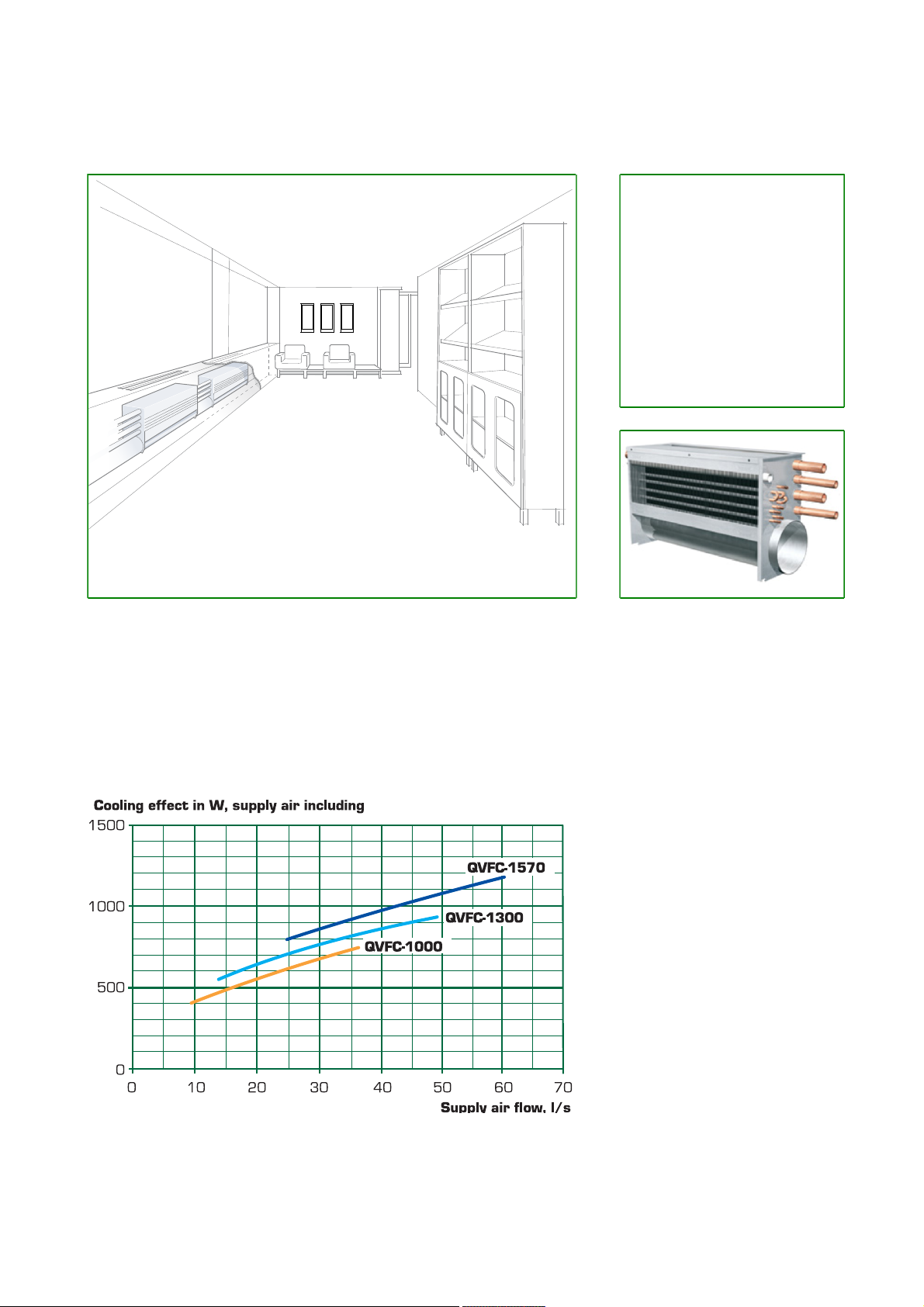
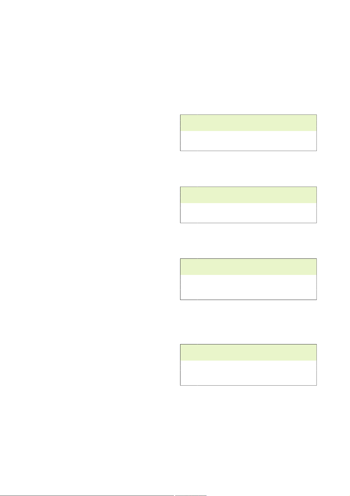
Perimeter wall system QVFC with heating, cooling and ventilation functions.
Perimeter wall systems use the supply air force to create an air fl ow through
induction that passes through the battery, which means that heated or
cooled air is blown out of the unit. The perimeter wall system is positioned
along the perimeter behind purpose built window benches. QVFC provides
high comfort in the occupied zone with individual control. Examples of
applications for perimeter wall systems are; offi ces, shops, schools, banks,
hospitals etc.
Quick Selection
Product Facts
• Heating, cooling and ventilation
functions
• Positioned along the perimeter
behind purpose built window
benches.
• High capacity and small space
requirement.
• Designed for both new build and
renovation and for replacing old
perimeter units.
• Automation and Control
Equipment as accessory.
Product code example
QVFB-1300-40-200
Perimeter wall system QVFC with
a nominal length 1300 mm , supply
air flow from the unit of 40 l/s and
pressure setting 200 Pa .
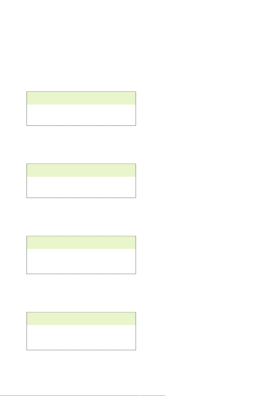
The diagram shows the approximate cooling ef fect, p
difference between supply air and r oom temperature, Δt = 8 °C and an operating pressure of 200 Pa .
Fläkt Woods 8976GB 2012.01 1
in W with a water flow of = 0,05 l/s , temperature
tot
Specifications are subject of alteration without further no tice.
Perimeter wall system QVFC
Technical data for cooling effect
Airflow, pressure and temperature
Several perimeter wall units connected together make an
installation branch.
The installation branch connection point is connected to
a supply air duct with a normal pressure of 200 Pa. At
lower pressure, for example 150 Pa, a lower cooling effect
is achieved. The airflow at the connection point is equal to
the total supply air flow along the installation branch.
The supply air can be supplied to the room at a
subnormal temperature of 8 °C cooler than the room
temperature due to the special design of the supply air
grille.
Heating and cooling effects
The tables on pages 2 and 3 display the cooling and
heating effects for QVFC at 200 Pa.
Cooling and heating effects are shown for the following
nominal lengths; 1000, 1300 and 1570 mm.
At operating pressure of 250 Pa the effects are increased
by approx. 10% compared to those values given.
At operating pressure of 150 Pa the effects are reduced by
approx. 10%.
The given effects apply to systems without casing. With
casing the effects increases with approx. 10%.
Total cooling effect
The total cooling effect is achieved by the cooling effect
from the supply air being added to the cooling effect from
the battery.
The cooling effect of the supply air is calculated as
follows:
(t
– t
room
t
= room air temperature in °C
room
t
air = Supply air temperature in °C
supply
q = Airflow in l/s
The heating capacity of the system is usually more than
sufficient and therefore seldom affects the size of the
system.
air ) x q x 1.2; where
supply
Cooling effect operating pressure of 200 Pa on air
side
Nominal length = 800 mm (Coil length = 500 mm)
Water flow, q w = 0,05 l/s
Pressure drop water, Δp w = 5,27 kPa
P
q l , l/s Δt, °C Δt, °C dB (A)
6 8 10 6 8 10
12,7 295 393 492 204 272 339 27
16,4 341 415 490 223 297 372 28
20,1 384 464 544 239 319 399 28
22,1 407 490 572 248 331 413 29
Nominal length = 1000 mm (Coil length = 700 mm)
Water flow, q w = 0,05 l/s
Pressure drop water, Δp w = 8,9 kPa
P
q l , l/s Δt, °C Δt, °C dB (A)
6 8 10 6 8 10
16 391 483 575 276 368 460 28
22 466 568 671 308 410 513 29
25 497 603 709 317 423 529 29
29 533 641 749 324 432 540 30
Nominal length = 1300 mm (Coil length = 1000 mm)
Water flow, q w = 0,05 l/s
Pressure drop water, Δp w = 11,4 kPa
P
q l , l/s Δt, °C Δt, °C dB (A)
6 8 10 6 8 10
22 542 669 797 383 511 639 28
24 561 690 819 388 517 646 28
30 620 755 890 404 539 647 29
37 683 821 960 416 555 694 30
42 722 861 1001 419 559 699 31
Nominal length = 1570 mm (Coil length = 1270 mm)
Water flow, q w = 0,05 l/s
Pressure drop water, Δp w = 2,6 kPa
(Two circuit coil gives lower pressure drop)
P
q l , l/s Δt, °C Δt, °C dB (A)
6 8 10 6 8 10
27 652 804 957 458 610 763 26
32 719 881 1044 488 651 814 27
39 789 958 1127 508 677 846 28
45 834 1004 1174 510 680 850 29
50 889 1065 1241 529 705 881 30
, w P
tot
, w P
tot
, w P
tot
, w P
tot
, w L
batt
, w L
batt
, w L
batt
, w L
batt
A10
A10
A10
A10
,
,
,
,
Fläkt Woods 8976GB 2012.01 2
Specifications are subject of alteration without further no tice.
Perimeter wall system QVFC
Technical data for heating effect
Heating effect at operating pressure of 200 Pa on
air side
Nominal length = 800 mm (Coil length = 500 mm)
Water flow, q w = 0,03 l/s
Pressure drop water, Δp w = 1,93 kPa
P
q l , l/s Δt, °C Δt, °C dB (A)
20 30 40 20 30 40
*)
169 253 337 169 253 337 >20
0
12,7 751 1126 1501 446 669 892 27
16,4 863 1098 1332 469 704 939 28
20,1 957 1194 1432 475 712 949 28
22,1 1010 1249 1489 479 719 959 29
*)
0 l/s = natural convection
Nominal length = 1000 mm (Coil length = 700 mm)
Water flow, q w = 0,03 l/s
Pressure drop water, Δp w = 1,2 kPa
P
q l , l/s Δt, °C Δt, °C dB (A)
20 30 40 20 30 40
*)
193 257 343 193 257 343 >20
0
16 655 1039 1347 693 924 1232 28
22 701 1163 1498 754 1005 1340 29
25 712 1209 1552 772 1029 1372 29
29 618 1241 1585 688 1032 1376 30
*)
0 l/s = natural convection
, W P
tot
, W P
tot
, W L
batt
, W L
batt
A10
A10
The above effects apply at the following ∆t:
8 °C for cooling and 30 °C for heating.
Correction of effects at other Δt
Example:
Δt at cooling effect 10 °C = effect in the table x (10/8) i.e.
Pbatt x 1.25
,
Δt at cooling effect 6 °C = effect in the table x (6/8) i.e Pbatt
x 0.75
etc
,
Nominal length = 1300 mm (Coil length = 1000 mm)
Water flow, q w = 0,03 l/s
Pressure drop water, Δp w = 1,5 kPa
P
q l , l/s Δt, °C Δt, °C dB (A)
20 30 40 20 30 40
*)
271 361 481 271 361 481 >20
0
22 932 1260 1698 985 1313 1751 28
24 953 1289 1738 1010 1347 1796 28
30 968 1315 1777 1040 1387 1849 29
37 846 1313 1781 935 1402 1869 30
42 972 1329 1806 1073 1430 1907 31
*)
0 l/s = natural convection
, W P
tot
, W L
batt
A10
Nominal length = 1570 mm (Coil length = 1270 mm)
Water flow, q w = 0,03 l/s
Pressure drop water, Δp w = 1,8 kPa
P
q l , l/s Δt, °C Δt, °C dB (A)
20 30 40 20 30 40
*)
318 424 565 318 424 565 >20
0
27 1129 1527 2058 1194 1592 2123 26
32 1152 1561 2107 1229 1638 2184 27
39 1139 1549 2097 1232 1643 2191 28
45 963 1499 2035 1071 1607 2143 29
50 1050 1440 1960 1170 1560 2080 30
*)
0 l/s = natural convection
, W P
tot
, W L
batt
A10
,
,
Fläkt Woods 8976GB 2012.01 3
Specifications are subject of alteration without further no tice.
 Loading...