


Centrimaster FV-600, FV-1000, FV-2000, FV-3000, FV-4000 Installation Manual
...Desiccant Wheel Products
FV Preconditioner Series
FV-600
FV-1000
FV-2000
FV-3000
FV-4000
FV-5000
FV-7500
FV-9000
Owner’s Manual

Table of Contents |
|
FV Outdoor Air Preconditioners ............................................................. |
1 |
Model Description ................................................................................... |
2 |
Definitions................................................................................................ |
2 |
Receiving & Inspection............................................................................ |
4 |
Storage ...................................................................................................... |
4 |
Overall Dimensions.................................................................................. |
4 |
Lifting Technique .................................................................................... |
5 |
Installation................................................................................................ |
5 |
Curb Mounting ........................................................................................ |
7 |
Unit Configuration .................................................................................. |
8 |
Supply & Exhaust Airflow Dampers ....................................................... |
9 |
Controls.................................................................................................. |
10 |
Basic Package ................................................................................... |
10 |
Optional Electric Preheat Frost Control ........................................ |
11 |
Optional Stop/Jog Economizer And Wheel Frost Protection ...... |
12 |
Optional Rotation Detector Sensor................................................ |
13 |
Thermostat Frost Control............................................................... |
13 |
3Ø Circuit Diagram, FV-600 ................................................................. |
14 |
3Ø Circuit Diagram, FV-1000 ............................................................... |
15 |
3Ø Circuit Diagram, FV-2000 through FV-9000.................................. |
16 |
1Ø Circuit Diagram, FV-600 ................................................................. |
17 |
1Ø Circuit Diagram, FV-1000 through FV-5000.................................. |
18 |
3Ø Electric Preheat Frost Control Circuit Diagram ............................ |
19 |
1Ø Electric Preheat Frost Control Circuit Diagram ............................ |
19 |
Electric Preheat Layout.......................................................................... |
20 |
Wheel Cassette ...................................................................................... |
21 |
Service..................................................................................................... |
22 |
Maintenance........................................................................................... |
22 |
AQFlow® Balancing Instructions........................................................... |
25 |
PowerTwist® Plus V-Belts ....................................................................... |
27 |
How To Reach SEMCO ........................................................................ |
29 |
How To Reach Fenner Drives................................................................ |
29 |
©1993-2010 SEMCO LLC. All rights reserved.
The information in this owner’s manual is furnished for informational use only, is subject to change without notice, and should not be construed as a commitment by SEMCO LLC. SEMCO assumes no responsibility for any errors that may appear in this owner’s manual.
No part of this publication may be reproduced, stored in a retrieval system or transmitted, in any form or by any means, electronic, mechanical, recording, or otherwise, without the prior written permission of SEMCO.
U.S. patented technology: 5,401,706 ; 5,496,397 ; 6,016,710
SEMCO, AQFlow, and EXCLU-SIEVE are registered trademarks of SEMCO LLC. PowerTwist Plus is a registered trademark of Fenner Drives.
i • FV Preconditioner Series Owner’s Manual
FV Outdoor Air Preconditioners
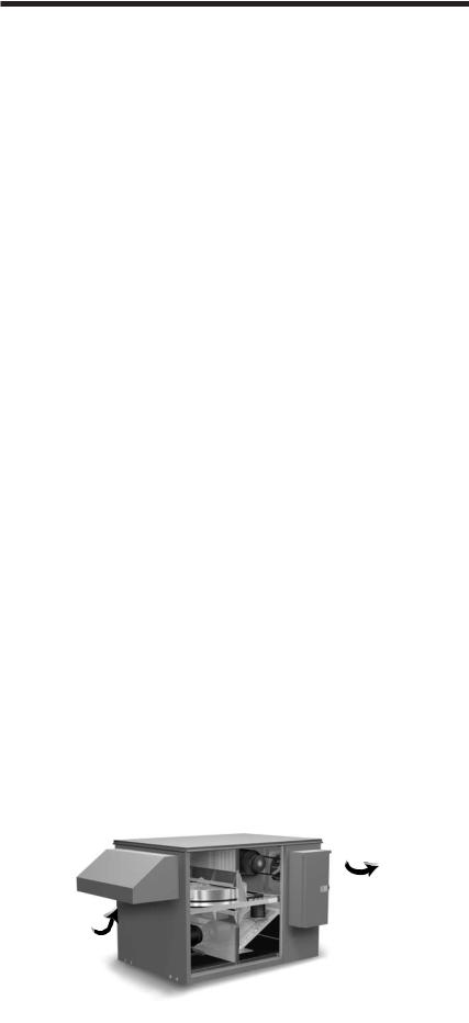
Figure 1. An inside view of the FV Series Preconditioner with typical operating temperatures during the cooling (C) and heating (H) season respectively.
The SEMCO FV Series of outdoor air preconditioners have been specifically designed to reduce the energy required to heat and cool outdoor air by as much as 80 percent. This unique capability allows both new and existing buildings to benefit from a healthy indoor environment by supplying high amounts of outside air in a very costeffective manner.
The FV preconditioner also allows HVAC systems to effectively and economically accommodate the increased outdoor air quantities recommended by the American Society of Heating, Refrigerating and Air Conditioning Engineers (ASHRAE) Standard 62. This standard guides the amount of ventilation air that should be introduced to a building to achieve acceptable indoor air quality.
The SEMCO FV system is a packaged system which includes supply and exhaust air fans, outdoor and return air filtration, and SEMCO’s EXCLU-SIEVE® total energy recovery wheel. The EXCLU-SIEVE wheel recovers both sensible (temperature) and latent (moisture) energy. Therefore, it cools and dehumidifies the outdoor air during the cooling season, while heating and humidifying the air in the heating season.
The EXCLU-SIEVE wheel utilizes a fluted aluminum sheet which is coated with a fast-acting, adsorbent desiccant. As the transfer media slowly rotates between the outdoor and exhaust airstreams, the higher temperature air gives up its sensible energy to the aluminum. This energy is then given up to the cooler airstream during the second half of the revolution. (See Figure 1.)
Just as the temperature is captured and released, so is the moisture. The EXCLU-SIEVE’s molecular sieve desiccant coating has a strong attraction to water vapor. Since the opposing airstreams have different temperature and moisture contents, they also have different vapor pressures. This difference provides the driving force that causes the transfer of latent energy.
Through the use of a patented 3Å molecular sieve desiccant coating, EXCLU-SIEVE recovers the moisture from an exhaust airstream without transferring the airborne pollutants contained within the exhaust airstream to the supply airstream. This important and unique feature has been well documented through independent laboratory and field testing. A copy of the report is available upon request.
Exhaust Air
(C) 90°F, 99 gr/lb
(H) 21°F, 9 gr/lb
Outdoor Air 
(C) 95°F, 110 gr/lb
(H) 5°F, 4 gr/lb
|
Return Air |
Supply Air |
(C) 75°F, 65 gr/lb |
(C) 80°F, 76 gr/lb |
(H) 70°F, 32 gr/lb |
(H) 54°F, 25 gr/lb |
|
FV Preconditioner Series Owner’s Manual • 1
Model Description
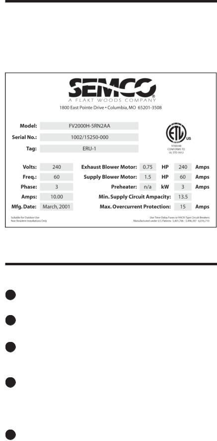
On the front of the FV unit is an identification label. The specifications on the label correspond to the actual unit. The model number (600, 1000, 2000, etc.) refers to the nominal air volume (in cfm) that the FV preconditioner is capable of supplying.
Definitions
1Adsorption – The physical bonding of water vapor on the surface of the desiccant.
2Cassette – The framework supporting the wheel. (See also Wheel.)
3Desiccant – A naturally occurring or man-made material with a high affinity for water vapor. SEMCO uses a highly selective 3Å molecular sieve desiccant material which minimizes cross contamination.
4Enthalpy wheel – A common term used to describe all rotating, wheel-shaped heat transfer devices that exchange sensible (temperature) and latent (water vapor) energy from one airstream to another. The word, enthalpy, means heat content or total heat. The term, enthalpy exchanger, may also be used.
5Exhaust air – The air from indoors that passed through the energy recovery wheel and is being ducted outdoors.
Figure 2. Typical FV nameplate with electrical data.
2 • FV Preconditioner Series Owner’s Manual
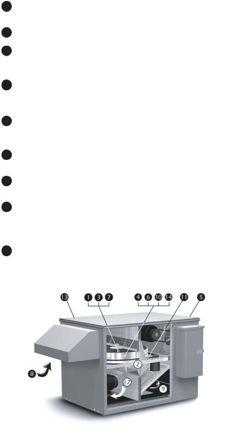
6Heat wheel – This generally describes all rotating devices which transfer only sensible energy.
7Media – The corrugated material inside the wheel.
8Outdoor air – The fresh outside air that is being drawn in the energy recovery wheel. Once it passes through the wheel it becomes the supply air.
9Return air – Air from the indoor space that is pulled through the energy recovery wheel. Once it passes through the wheel it is referred to as exhaust air.
10Rotor – The media-filled wheel that rotates. It transfers heat energy and water vapor from one ducted airstream to the other. Often, the rotor will be referred to as a wheel.
11Seal – The soft material that closely surrounds the rotor to limit the amount of bypass air around the rotor.
12Supply air – Air provided to the indoor space. Outside air that passes through the energy recovery wheel becomes supply air.
13Unit – Used frequently throughout this manual to mean the EXCLU-SIEVE Energy Recovery Wheel and attendant components such as cabinets, motors, fans and other parts that work together to make an effective energy recovery product.
14Wheel – Refers to the rotating wheel containing the coated media. The stationary framework supporting the wheel is the wheel cassette.
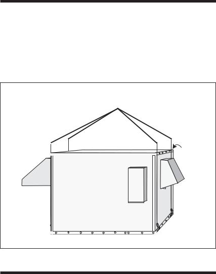
Figure 3. Typical FV unit with components highlighted per definitions above.
FV Preconditioner Series Owner’s Manual • 3
Receiving & Inspection
Upon delivery, confirm that the quantity and model(s) received matches the Bill of Lading. If there is any discrepancy, immediately notify SEMCO.
Inspect the skidded FV(s) for signs of damage. If damage is suspected, sign the Bill of Lading “damaged”. If no visible damage is apparent, the unit should be properly lifted and stored until installation.
While skidded, the FV can be lifted by a forklift using the skid. Once removed from the skid, lifting must only be performed with spreader bars, cable and hooks. Do not attempt to lift the FV by grasping the hoods.
Note: In the table of weights on the right, the package weighs approximately 100 lbs. more than the net weight.
Storage
If the FV is to be stored for any time before installation, it must be protected from the weather. Indoor storage is recommended. The unit has openings provided for ducting. These openings make the internal equipment (motors, belts, fans and insulation) vulnerable to inclement weather conditions (prior to installation) and can cause standing water to accumulate inside the enclosure. This is to be absolutely avoided.
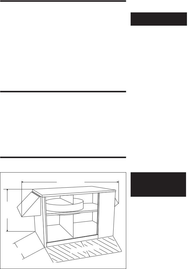
Overall Dimensions
|
L = Overall Length |
|
H = Height |
|
|
W = Width |
Service |
Clearance |
|
||
Model |
Net Weight |
|
(lbs) |
||
|
||
|
|
|
FV-600 |
450 |
|
|
|
|
FV-1000 |
500 |
|
|
|
|
FV-2000 |
550 |
|
|
|
|
FV-3000 |
1,000 |
|
|
|
|
FV-4000 |
1,150 |
|
|
|
|
FV-5000 |
1,150 |
|
|
|
|
FV-7500 |
1,800 |
|
|
|
|
FV-9000 |
1,800 |
|
|
|
Unit |
L |
H |
W |
|
|
|
|
|
Dimensions in |
||
|
|
inches |
|
|
|
|
|
FV-600 |
69.5 |
31.0 |
29.0 |
|
|
|
|
FV-1000 |
69.5 |
31.0 |
29.0 |
|
|
|
|
FV-2000 |
80.6 |
32.4 |
37.0 |
|
|
|
|
FV-3000 |
96.0 |
47.7 |
45.0 |
|
|
|
|
FV-4000 |
126.5 |
51.5 |
54.0 |
|
|
|
|
FV-5000 |
126.5 |
51.5 |
54.0 |
|
|
|
|
FV-7500 |
143.5 |
58.6 |
64.6 |
|
|
|
|
FV-9000 |
143.5 |
58.6 |
64.6 |
|
|
|
|
Service clearance is equal to the width of the unit.
4 • FV Preconditioner Series Owner’s Manual
Lifting Technique
When rigging the FV unit, spreader bars must be used. Padding must be inserted between the straps and the unit to avoid scratching the paint. Lifting holes are provided at four points located on the base perimeter of the FV unit. The weights shown on page 4 may be used as maximum weights for rigging.
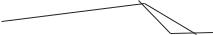
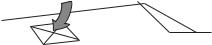
Figure 4. Correct lifting technique using spreader bars.
padding
Installation
Installation of the FV is a relatively simple procedure, but should be undertaken in a methodical fashion, following the directions outlined in this manual.
Note: Prior to starting unit, open access door and;
Remove loose parts shipped inside;
Remove wheel shipping restraint (FV-3000 thru FV-9000 only).
The installation location should be chosen to provide easy, convenient access. As with all mechanical equipment, routine maintenance and inspection is necessary. Choose a site from which connecting duct is visible. Avoid locations that are near or downwind of smoke, fumes or exhaust outlets of other equipment. The front access panel should have clearance space equal to the depth of the unit to allow for service.
Once the installation location is determined, the FV should be skidded and closely examined. Any defects or problems should be reported to SEMCO immediately.
Several ducting arrangements are possible. Make sure your duct plans match the FV duct opening arrangement. (See Unit Configuration, p.8).
FV Preconditioner Series Owner’s Manual • 5
The FV can be ordered for indoor or outdoor installation. An outdoor unit is identified by the existence of two hoods that are shipped on top of the FV unit. It will be necessary to attach the outdoor air intake hood (larger one with filter rack) and the exhaust air outlet hood (smaller one with damper) on their designated openings (see Figure 6a-d). The indoor unit is identified by a rectangular duct shipped on top of the unit. This indoor intake duct must be installed over the outdoor air intake opening (see Figure 6a-d). Use the given alignment holes to place the hood or duct in the correct position.
If the unit is a rooftop unit, it may be installed on a curb. If SEMCO supplies the curb, then it will have been shipped separately. The curb must be installed before a rooftop FV can be placed. Proper care should be taken to ensure correct placement of the curb before holes are cut for ducting through the roof itself. Effective waterproofing of the rooftop interface is necessary. That means sealing around the roof curb to prevent any leakage into the building or the air ducts. The curb and FV must be installed and operated in a horizontal position.
If the unit is not installed on the roof, then a concrete or paved pad to support the FV must be provided. The pad must be of sufficient height and located to assure proper water drainage in any weather.
Inspect the interior of the unit for any damage. On the floor inside the unit is the outdoor air metal filter. This filter is to be installed at the outdoor air intake opening after the hood (outdoor FV only) has been attached. On the FV-3000, FV-4000, FV-5000, FV-7500, and FV-9000 remove wheel shipping restraint.
The SEMCO energy recovery wheel is mounted horizontally inside the FV. The motor and belt arrangement that turn the wheel are visible next to the wheel at the access panel opening. The motor wires running to the control panel are attached by a quick release disconnect. The quick disconnect must be separated before sliding out the wheel cassette. The wheel cassette need not be moved for installation or hookup, but it can be pulled out for easy maintenance and inspection purposes.
When the unit has been placed in its permanent location, duct work should be brought up to and attached to the unit. Duct work may be flanged and screwed to the unit face for horizontal connections. Duct work for a vertical unit should be flanged and gasketed level with the curb to allow the unit weight to form the seal. Penetrations through the unit floor must be avoided to prevent any water penetrating into the cabinet.
If the unit has been ordered with electric preheat, it is shipped installed. The main power connection to the unit is made at the electric coil instead of the unit control panel. For the indoor version of the FV, the electric coil should be externally insulated after installation.
On the front right side of the FV is the unit identification tag. It states the electrical requirements for the unit. (If electric preheat option has been ordered, the unit ID tag is located on the heater.) Make sure the power provided to the installation site matches that required by the unit. Note and verify that voltage/phase/capacity needed and provided are the same, and the line voltage must not vary more than +/-5%.
6 • FV Preconditioner Series Owner’s Manual
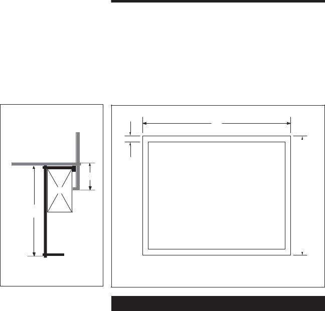
Curb detail |
FV-Unit |
E |
Nailer |
D |
Roof Curb |
Elevation |
Figure 5. Curb dimensions.
Curb Mounting
The FV series is generally installed on a curb (unless mounted indoors). The curb ships separately for preinstallation to simplify rigging. The dimensions of the curbs required for the FV units are listed below.
All FV configurations have the same curb dimensions. The curb for an FV unit can be provided by SEMCO or purchased from a curb manufacturer provided it is designed to support the weight of the FV unit specified in this manual and conforms to the dimensions listed in the table below.
A |
C |
B |
Plan View |
Model |
A |
B |
C |
D |
E |
|
|
|
|
|
|
FV-600 |
40.1 |
25.0 |
1.7 |
14.0 |
3.0 |
|
|
|
|
|
|
FV-1000 |
40.1 |
25.0 |
1.7 |
14.0 |
3.0 |
|
|
|
|
|
|
FV-2000 |
47.4 |
33.0 |
1.7 |
14.0 |
2.0 |
|
|
|
|
|
|
FV-3000 |
60.6 |
41.0 |
1.7 |
14.0 |
3.0 |
|
|
|
|
|
|
FV-4000 |
74.6 |
49.9 |
1.7 |
14.0 |
3.0 |
|
|
|
|
|
|
FV-5000 |
74.6 |
49.9 |
1.7 |
14.0 |
3.0 |
|
|
|
|
|
|
FV-7500 |
91.0 |
60.3 |
1.7 |
14.0 |
3.0 |
|
|
|
|
|
|
FV-9000 |
91.0 |
60.3 |
1.7 |
14.0 |
3.0 |
|
|
|
|
|
|
All dimensions in inches.
FV Preconditioner Series Owner’s Manual • 7

Unit Configuration
The FV preconditioner can be installed in one of four possible configurations depending on the arrangement of the supply and return air openings.
Exhaust Air Out
Outdoor Air In
 Return Air
Supply Air
Figure 6a. H Series configuration with horizontal supply air and horizontal return air duct arrangement.
Exhaust Air Out
Outdoor Air In
Supply Air
Return Air
Figure 6b. HS Series configuration with horizontal supply air and vertical return air duct arrangement.
Exhaust Air Out
Outdoor Air In
 Return Air
Supply Air
Figure 6c. V Series configuration with vertical supply air and vertical return air duct arrangement.
Exhaust Air Out
Outdoor Air In
 Return Air
Supply Air
Figure 6d. VS Series configuration withverticalsupplyairandhorizontal return air duct arrangement.
8 • FV Preconditioner Series Owner’s Manual
 Loading...