

Page 1
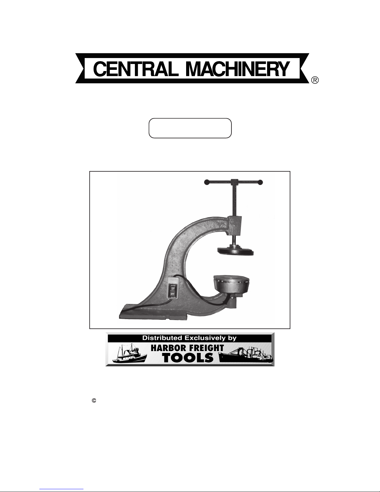
TIRE PATCHING MACHINE
®
Model 46616
ASSEMBLY AND OPERATING INSTRUCTIONS
3491 Mission Oaks Blvd., Camarillo, CA 93011
Visit our Web site at: http://www.harborfreight.com
Copyright 2002 by Harbor Freight Tools®. All rights reserved. No portion of this
manual or any artwork contained herein may be reproduced in any shape or form with-
out the express written consent of Harbor F reight Tools.
For technical questions, please call 1-800-444-3353.
Page 2

SPECIFICATIONS TABLE
Item Descript i on
Electrical Require m ents 120 V / 60 Hz / 7 Amp / Single Phase
Maximum Controlled Temperature 275 Degrees Fahrenheit
Hot Plate 4-7/8” x 8” Oval Shape
Height 16” Closed Position
22” Open Po sition
Depth 14-3/8” Front to Back
Width 8” At Plate
Handle Sliding w/Handle
Weight 31.40 Pounds
SAVE THIS MANU AL
You will need this manual for the safety warnings and precautions, assembly,
operating, inspection, maintenance and cleaning procedures, parts list and
assembly diagram. Keep your invoice with this manual. Write the invoice number on the inside of the front cover. Keep this manual and invoice in a safe and
dry place for future reference.
GENERAL SAFETY WARNINGS AND PRECAUTIONS
1. KEEP WORK AREA CLEAN AND DRY. Cluttered, damp, or wet work areas
invite injuries.
2. KEEP CHILDREN AWAY FROM WORK AREA. Do not allow children to handle
this product.
3. STORE IDLE EQUIPMENT. When not in use, tools and equipment should be
stored in a dry location to inhibit rust. Always lock up tools and equipment, and
keep out of reach of children.
4. DO NOT USE THIS PRODUCT IF UNDER THE INFLUENCE OF ALCOHOL OR
DRUGS. Read warning labels on prescriptions to determine if your judgement or
reflexes are impaired while taking drugs. If there is any doubt, do not attempt to
use this product.
5. USE EYE AND HAND PROTECTION. Wear ANSI approved safety impact
goggles and heavy-duty work gloves when using this product. ANSI approved
safety impact goggles and heavy-duty work gloves are available from Harbor
Freight Tools.
SKU 46616 PAGE 2
Page 3

6. DRESS SAFELY. Do not wear loose clothing or jewelry, as they can become
caught in moving parts. Wear a protective hair covering to prevent long hair from
becoming caught in moving parts. If wearing a long-sleeve shirt, roll sleeves up
above elbows.
7. DO NOT OVERREACH. Keep proper footing and balance at all times to prevent
tripping, falling, back injury, etcetera.
8. INDUSTRIAL APPLICATIONS MUST FOLLOW OSHA REQUIREMENT.
9. STAY ALERT. Watch what you are doing at all times. Use common sense. Do
not use this product when you are tired or distracted from the job at hand.
10. CHECK FOR DAMAGED PARTS. Before using this product, carefully check that
it will operate properly and perform its intended function. Check for damaged
parts and any other conditions that may affect the operation of this product.
Replace or repair damaged or worn parts immediately.
11. REPLACEMENT PARTS AND ACCESSORIES: When servicing, use only
identical replacement parts. Only use accessories intended for use with this
product. Approved accessories are available from Harbor Freight Tools.
12. MAINTAIN THIS PRODUCT WITH CARE. Keep this product clean and dry for
better and safer performance.
13. MAINTENANCE: For your safety, service and maintenance should be performed
regularly by a qualified technician.
14. USE THE RIGHT TOOL FOR THE JOB. Do not attempt to force a small tool or
attachment to do the work of a larger industrial tool. There are certain
applications for which this tool was designed. It will do the job better and more
safely at the rate for which it was intended. Do not modify this tool, and do not
use this tool for a purpose for which it was not intended.
15. WARNING: The warnings, precautions, and instructions discussed in this
manual cannot cover all possible conditions and situations that may occur. The
operator must understand that common sense and caution are factors, which
cannot be built into this product, but must be supplied by the operator.
SPECIFIC PRODUCT WARNINGS AND PRECAUTIONS
1. TO AVOID ACCIDENTAL FIRE, DO NOT USE TIRE TUBE CEMENTS OR
SOLVENTS HAVING A FLASH/IGNITION POINT OF LESS THAN 350
DEGREES FAHRENHEIT.
SKU 46616 PAGE 3
Page 4

1. (cont.)When turned on, the Tire Patching Machine quickly heats up and maintains a maximum temperature of 275 degrees Fahrenheit. Before using the Tire
Patching Machine, make sure you read and fully understand the warnings and
precautions as outlined in the manufacturer’s manual of the cement or solvent
you are using.
2. NEVER LEAVE THE TIRE PATCHING MACHINE UNA TTENDED WHEN IT IS
HOT. At all times, stay with the Tire Patching Machine when it is turned on. After
turning off the Tire Patching Machine, stay with it until it’s Heating Plate (part
#12) cools to room temperature.
3. MAINTAIN A SAFE WORKING ENVIRONMENT. Keep the work area well lit.
Make sure there is adequate surrounding workspace. Always keep the work
area free of obstructions, grease, oil, trash, and other debris. Do not use the Tire
Patching Machine in areas near flammable chemicals, dusts, and vapors.
4. GROUND THIS PRODUCT . The electrical Power Cord for this product is
equipped with a grounded, 3-prong Plug. Never remove the grounding prong or
modify the Plug in any way. Do not use adapter plugs with this product. To
comply with the National Electric Code, and to provide additional protection from
the risk of electrical shock, this product should only be connected to a 120 Volt,
3-hole electrical outlet that is protected by a Ground Fault Circuit Interrupter
(GFCI).
5. IF AN EXTENSION CORD (not provided) IS USED, MAKE SURE TO USE
ONLY UL APPROVED CORDS HAVING THE CORRECT GAUGE AND
LENGTH. (See Figure A.)
AWG RATING CHART - 120 VOLT
FIGURE A
6. Important Note: When using the Tire Patching Machine f or the first time, the tool
may smoke when plugged in and turned ON, due to forming oil being burnt off the cast
iron plate inside the housing. This is a normal occurance; the machine should be turned
on for appro ximately 15 minutes to allow this to occur, before the first use of the machine.
7. WARNING: This product contains or produces a chemical known to the State of
California to cause cancer and birth defects (or other reproductive harm).
(California Health & Safety Code 25249.5 et seq.)
SKU 46616 PAGE 4
REV 03/04
Page 5

8. WARNING: People with pacemakers should consult their physician(s) before
using this product. Operation of electrical equipment in close proximity to a heart
pacemaker could cause interference or failure of the pacemaker.
UNPACKING
When unpacking, check to make sure all the parts shown on the Parts List (page 8) are
included. If any parts are missing or broken, please call Harbor Freight Tools at the
number shown on the cover of this manual as soon as possible.
ASSEMBLY AND OPERATING INSTRUCTIONS
NOTE: For additional references to the par ts listed below, refer to the Assembly Dia-
gram (page 8).
To Mount The Tire Patching Machine On A Workbench:
1. Caution: Make sure the Tire Patching Machine is securely mounted on a flat,
level, sturdy, wor kbench capable of supporting the weight of the Tire Patching
Machine, tools, accessories, and work piece.
2. There are two 1/2” wide mounting slots located at the bottom right and left sides
of the Main Frame (part #3). (See Assy. Diagram.)
3. With assistance, set the Tire Patching Machine in the desired location on the top
of the workbench. Using the two mounting slots as a template, mark the two
holes that are to be drilled through the top of the workbench. Then, temporarily
remove the Tire Patching Machine.
4. Using a drill and 1/2” drill bit (not provided), drill the two previously marked holes
completely through the top of the workbench.
5. Align the two 1/2” mounting slots at the right and left ends of the Main Frame
(part #3) with the two previously drilled holes in the workbench. Then, firmly
secure the Tire Patching Machine to the workbench with two appropriate length
1/2” bolts, two lock washers, and two nuts (not provided).
To Prepare The Tire Tube For Patching:
1. Carefully remove the tube valve stem from the tire tube, and allow all of its air to
escape. Then, remove the tube from the tire.
SKU 46616 PAGE 5
REV 03/04
Page 6

2. Firmly screw the tube valve stem back into the tire tube. Then, re-inflate the tube
according to the tire tube manufacturer’s recommended PSI air pressure.
3. Fully submerge the tire tube in a tank of water, and observe air bubbles escaping
from the hole in the tube. Then remove the tube from the water tank and, with
chalk, mark the location of the hole.
4. Carefully remove the tube
valve stem from the tire tube, and allow all of its air to
escape.
5. Using
sandpaper, or a scraper made especially for this pur pose, rough up the
area around the hole.
To Operate The Tire Patching Machine:
1. Apply an all-purpose, fast dry, rubber cement on the area around the hole. Make
sure to allow the cement to dry. Then, apply the prepared side of an
appropriate size tube patch to the tire tube (the side with the colored peel-off).
2. Place the tire tube on the Heating Box Cover (part #7) of the Tire Patching
Machine. Make sure the tube patch is resting downward, directly on the
surface of the Heating Box Cover. (See Assy. Diagram.)
3. Turn the Handle (par t #16)
clockwise
to lower the Press Plate (part #4) until the
tire tube is held firmly in place between the Heating Box Cover (part #7) and the
Press Plate. (See Assy. Diagram.)
4. Connect the Power Cord/Plug (part #17) to a grounded, 3-prong, 120 volt,
electrical outlet. (See Assy. Diagram.)
5. Turn the Switch (part #19) to its “ON” position. (See Assy. Diagram.)
6. Allow 20 to 30 minutes for the Tire Patching Machine to heat up and firmly
adhere the tube patch to the tire tube.
7. Then, turn the Switch (part #19) to its “OFF” position, and disconnect the Power
Cord/Plug (part #17) from its electrical outlet. (See Assy. Diagram.)
8. Turn the Handle (part #16)
#4), and remove the tire tube from the Tire Patching Machine. (See Assy.
Diagram.)
9. Firmly screw the tire tube valve stem back into the tube. Then, re-inflate the tube
according to the tire tube manufacturer’s recommended PSI air pressure.
SKU 46616 PAGE 6
counterclockwise
to fully raise the Press Plate (part
Page 7

10. Fully submerge the tire tube in a tank of water to make sure no air bubbles are
escaping from the tube. If no air bubbles are observed, the tire tube has
been successfully patched.
11. Carefully remove the tube
valve stem from the tire tube, and allow all of its air to
escape. Then, re-install the tire tube in the tire.
INSPECTION, MAINTENANCE, AND CLEANING
1. CAUTION: Always disconnect the Tire Patching Machine from its electrical power
source before performing any inspection, maintenance, or cleaning.
2. BEFORE EACH USE, inspect the general condition of the Tire Patching
Machine. Check for loose screws, misalignment or binding of moving parts,
cracked or broken parts, damaged electrical wiring, any other condition that may
affect its safe operation. If abnormal noise or vibration occurs, have the problem
corrected before further use. Do not use damaged equipment.
3. PERIODICALLY, use a premium quality, lightweight machine oil to lubricate all
moving parts.
4. When necessary, wipe with a damp cloth, using a mild detergent or mild solvent.
PLEASE READ THE FOLLOWING CAREFULLY
THE MANUF ACTURER AND/OR DISTRIBUT OR HAS PRO VIDED THE PARTS LIST AND ASSEMBLY
DIAGRAM IN THIS MANUAL AS A REFERENCE TOOL ONLY. NEITHER THE MANUFACTURER OR
DISTRIBUTOR MAKES ANY REPRESENTATION OR WARRANTY OF ANY KIND TO THE BUYER
THA T HE OR SHE IS QU ALIFIED TO MAKE ANY REPAIRS TO THE PRODUCT, OR THA T HE OR SHE
IS QUALIFIED TO REPLACE ANY PARTS OF THE PRODUCT. IN FACT, THE MANUFACTUER AND/
OR DISTRIBUTOR EXPRESSLY STATES THA T ALL REP AIRS AND PAR TS REPLACEMENTS SHOULD
BE UNDERT AKEN BY CERTIFIED AND LICENSED TECHNICIANS, AND NOT BY THE BUYER. THE
BUYER ASSUMES ALL RISK AND LIABILITY ARISING OUT OF HIS OR HER REPAIRS TO THE
ORIGINAL PRODUCT OR REPLACEMENT PARTS THERETO, OR ARISING OUT OF HIS OR HER
INSTALLATION OF REPLACEMENT PARTS THERET O .
SKU 46616 PAGE 7
Page 8

#
#
PARTS LIST / ASSEMBLY DIAGRAM
Part
1 Handle Ball 2 11 Nut 2
2 Adjusting Screw 1 12 Heating Plate 1
3 Main Frame 1 13 Big Adapter 1
4 Press Plate 1 14 Small Adapter 1
5 Bolt (M5 x 15) 2 15 Heating Pipe 1
6 Heating Box 1 16 Handle 1
7 Heating Box Cover 1 17 Power Cord/Plug 1
8 Temperature Monitor 1 18 Rubber Grommet 1
9 Bolt (M5 x 10) 1 19 Switch 1
10 Washer 2
Description Qty. Part
Description Qty.
NOTE: Some parts are listed and shown for illustration purposes only, and are not
available individually as replacement parts.
SKU 46616 PAGE 8
 Loading...