

Page 1
8 INCH DRILL PRESS
®
MODEL 44506
ASSEMBLY AND OPERATING
INSTRUCTIONS
3491 Mission Oaks Blvd., Camarillo, CA 93011
Visit our Web site at http://www.harborfreight.com
Copyright© 2000 by Harbor Freight Tools®. All rights reserved. No portion of this
manual or any artwork contained herein may be reproduced in any shape or
form without the express written consent of Harbor Freight Tools.
For technical questions and replacement parts, please call 1-800-444-3353.
Page 2

Specifications
METINOITPIRCSED
rotoM
sdeepSeldnipS.MPR0013dna,0432,0271,0011,
ekortSeldnipShcni2
nmuloCsehcni)H(4/1-51x)retemaid(98.1
snoisnemiDesaBhcni61/9:tolS;sehcni7x8/1-11
nemiDllarevOsehcni)W(2/1-7x)D(8/5-51x)H(32
htpeDtaorhT)gniwshcni8fo(sehcni4
yticapaCkcuhChcni2/1otpU
baTsehcni8/5
tolSel
noitatoRelbaT)thgirdnatfel(°54:tliT;°063
eziSelbaTsehcni8/3-6x8/5-6
thgieW.sbl04
120
snois
Save This Manual
Control
# 86PJ
;MPR0571,PH3/1,zH06,CAV011
)daolhtiw(spma6.3
026
E172674
You will need the manual for the safety warnings and precautions, assembly instructions,
operating and maintenance procedures, parts list and diagram. Keep your invoice with this
manual. Write the invoice number on the inside of the front cover. Keep the manual and
invoice in a safe and dry place for future reference.
Safety Warnings and Precautions
WARNING: When using tool, basic safety precautions should always be followed to
reduce the risk of personal injury and damage to equipment.
Read all instructions before using this tool!
1. Keep work area clean. Cluttered areas invite injuries.
2. Observe work area conditions. Do not use machines or power tools in damp or wet
locations. Don’t expose to rain. Keep work area well lighted. Do not use electrically
powered tools in the presence of flammable gases or liquids.
3. Keep children away. Children must never be allowed in the work area. Do not let
them handle machines, tools, or extension cords.
4. Store idle equipment. When not in use, tools must be stored in a dry location to
inhibit rust. Always lock up tools and keep out of reach of children.
5. Do not force tool. It will do the job better and more safely at the rate for which it was
intended. Do not use inappropriate attachments in an attempt to exceed the tool
capacity.
SKU 44506 For technical questions, please call 1-800-444-3353. Page 2
REV 07/06
Page 3

6. Use the right tool for the job. Do not attempt to force a small tool or attachment to
do the work of a larger industrial tool. There are certain applications for which this tool
was designed. Do not modify this tool and do not use this tool for a purpose for which
it was not intended.
7. Dress properly. Do not wear loose clothing or jewelry as they can be caught in
moving parts. Protective, electrically nonconductive clothes and nonskid footwear are
recommended when working. Wear restrictive hair covering to contain long hair.
8. Use eye and ear protection. Always wear ANSI approved impact safety goggles.
Wear a full face shield if you are producing metal filings or wood chips. Wear an ANSI
approved dust mask or respirator when working around metal, wood, and chemical
dusts and mists.
9. Do not overreach. Keep proper footing and balance at all times. Do not reach over or
across running machines.
10. Maintain tools with care. Keep tools sharp and clean for better and safer
performance. Follow instructions for lubricating and changing accessories. Inspect tool
cords periodically and, if damaged, have them repaired by an authorized technician.
The handles must be kept clean, dry, and free from oil and grease at all times.
11. Disconnect power. Unplug when not in use.
12. Remove adjusting keys and wrenches. Check that keys and adjusting wrenches
are removed from the tool or machine work surface before plugging it in.
13. Avoid unintentional starting. Be sure the switch is in the Off position when not in
use and before plugging in.
14. Stay alert. Watch what you are doing, use common sense. Do not operate any tool
when you are tired.
15. Take caution as some woods contain preservatives such as copper chromium
arsenate (CCA) which can be toxic. When cutting these materials extra care should
be taken to avoid inhalation and minimize skin contact.
16. Check for damaged parts. Before using any tool, any part that appears damaged
should be carefully checked to determine that it will operate properly and perform its
intended function. Check for alignment and binding of moving parts; any broken parts
or mounting fixtures; and any other condition that may affect proper operation. Any
part that is damaged should be properly repaired or replaced by a qualified technician.
Do not use the tool if any switch does not turn On and Off properly.
17. Guard against electric shock. Prevent body contact with grounded surfaces such as
pipes, radiators, ranges, and refrigerator enclosures.
18. Replacement parts and accessories. When servicing, use only identical
replacement parts. Use of any other parts will void the warranty. Only use accessories
intended for use with this tool. Approved accessories are available from Harbor Freight
Tools.
SKU 44506 For technical questions, please call 1-800-444-3353. Page 3
Page 4

19. Do not operate tool if under the influence of alcohol or drugs. Read warning
labels on prescriptions to determine if your judgment or reflexes are impaired while
taking drugs. If there is any doubt, do not operate the tool.
20. Use proper size and type extension cord. If an extension cord is required, it must
be of the proper size and type to supply the correct current to the tool without heating
up. Otherwise, the extension cord could melt and catch fire, or cause electrical
damage to the tool. This tool requires use of an extension cord of 0 to 12 amps
capability (up to 50 feet), with wire size rated at 16 AWG. Longer extension cords
require larger size wire (smaller AWG number). If you are using the tool outdoors, use
an extension cord rated for outdoor use (signified by “WA” on the jacket).
21. Secure Workpiece. Use clamps or a vise to hold workpiece, if possible. Never hold
workpiece with your hands.
22. Never leave Drill Press running unattended. Turn the power OFF.
23. Maintenance. For your safety, service and maintenance should be performed
regularly by a qualified technician.
Note: Performance of this tool may vary depending on variations in local line voltage. Extension cord usage may also affect tool performance.
Warning: The warnings, cautions, and instructions discussed in this instruction manual
cannot cover all possible conditions and situations that may occur. It must be understood by the operator that common sense and caution are factors which cannot be
built into this product, but must be supplied by the operator.
Drill Press Safety Warnings and Precautions
1. Secure the Drill Press Base to a table using Bolts (not supplied). The table must be
appropriate for use with a drill press and be located on a hard, flat, level surface.
2. Locate the Drill Press in an area where you walk around it unhampered.
3. Avoid kickback and grabbing by clamping the workpiece to the table, or use a vise that
is secured to the table. If the workpiece begins to spin, do not attempt to stop it with
your hands. Turn the motor OFF, and wait until it stops spinning before attempting to
remove it.
4. Avoid being caught and pulled into the spinning chuck. Do not wear gloves, long
sleeve shirts, ties, or jewelry. Long hair must be bundled behind the head.
5. Never place hands and arms near the workpiece to avoid the possibility of the
workpiece coming loose and striking you.
6. Before drilling, turn on the motor and check for bit wobble or machine vibration. If this
is found, correct the problem before drilling.
7. Set the proper spindle speed for the specific drilling operation.
8. When finished with the Drill Press, always press the Switch to the OFF position.
SKU 44506 For technical questions, please call 1-800-444-3353. Page 4
Page 5
9. Do not mount (or adjust) the workpiece on the Drill Press Table while the motor is
running.
10. When drilling or cutting large holes, use the slower speeds and securely fasten the
workpiece to the table using a mounted vise.
11. Do not use drill bits that extend more than six inches from the Chuck.
12. Do not use circle cutters, rotary planers, wire wheels, router bits, or shaper cutters on
this Drill Press.
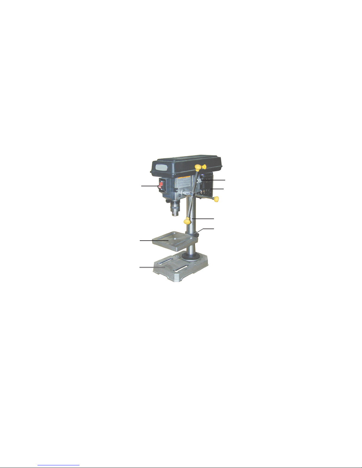
Unpacking
When unpacking, check to make sure the following parts are included. Refer to the Parts
Lists and Assembly Drawings located at the end of this manual.
Locking Switch (21)
Table (C7)
Base (C4)
Head (1) Assembly
Motor (7)
Support Tube (C3)
Table Support (C1)
Bag of Loose Parts
Box of Loose Parts
If any parts are missing or broken, please call Harbor Freight Tools at the number on the
cover of this manual as soon as possible.
Assembly
Assembly hardware is located in one box and one bag. Each contains the necessary parts
for each assembly step. Remove all packing and protective material from the Drill Press
components.
1. Position the Base (C4) on a level and sturdy table for mounting.
It is recommended to bolt the Base to the table using appropriate hardware (not
supplied).
2. Place the Support Tube (C3) on the Base, aligning the mounting holes.
3. Insert three large Hex Screws (C5) into the mounting holes and tighten with a wrench.
SKU 44506 For technical questions, please call 1-800-444-3353. Page 5
Page 6

4. Install the Table Support (C1), with attached Table (C7), over the Support Tube (C3)
and slide it down. Hand Tighten the Lock Handle Support (C2).
CAUTION: Avoid injuries. The next step involves lifting the Head Assembly onto the
Support Tube. The Head Assembly is heavy. Have someone help you lift this assembly
into place.
5. Using two people, lift the Head (1) Assembly up and onto the Support Tube (C3).
Slide it down on the Column Tube as far as it will go. Align it so that it faces straight
forward, inline with the Base.
6. Screw in two Set Screws (11), into the side of the Head (1) and tighten with the Allen
wrench.
Guard (A5)
Motor Adjusting
Knob (10)
Feed Knob (12)
Hex Nuts (31)
Feed Wheel Stop
Tension Spring (28)
Chuck (B8)
Set Screws
(11)
7. Attach Knob (A2) to the (top) pulley Guard (A5) using Pan Head Screw (A3).
8. Adjust Belt (A4) tension or change speeds.
- Open the pulley Guard (A5) to expose the Belt.
- Turn the Motor Adjusting Knob (10) counterclockwise to loosen Belt Tension.
- If necessary, move the Belt up or down on the pulleys to change the drill speed.
- Push the Motor backward, tightening the Belt on the pulleys, and hold in place.
- Turn the Motor Adjusting Knob clockwise to tighten the Belt in place.
- Refer to the chart inside the Guard lid to select speed and belt locations.
Knob (A2)
Note: To test the proper belt tension, push in on the center of each belt at its center. It should
move only 1/2 inch (in or out).
Caution: overtightening the belts can cause the motor to bind, and not start. It can also
damage Motor bearings.
9. Locate the Feed Knobs (12) and Rods (13) and screw onto the Pinion Shaft (14).
10. Install the Chuck (B8).
- Thoroughly clean the tapered hole in the Chuck and the Spindle Shaft (B7) of all dirt,
grease, oil, and protective coatings (paint thinner may be necessary).
SKU 44506 For technical questions, please call 1-800-444-3353. Page 6
Page 7

- Slide the Chuck onto the Spindle Shaft.
- Turn the Chuck sleeve clockwise and open the jaws
completely.
- Tap the nose of the Chuck lightly with a piece of wood
and a hammer to securely set the Chuck.
11. Verify that the Table (C7) is square (90 degrees) to the
Head Assembly and drill bit.
Screw (C6)
- Raise the Table to within four inches of the Chuck.
- Place the long side of a combination square on the
Table.
- Align the short side of the square to the drill bit.
- If the Table is not square to the bit, loosen Screw (C6)
with a wrench.
- Rotate the Table until it is square to the bit.
- Retighten the Screw (C6).
Operation
Warning: Avoid personal injuries. Before operating this machine, review all Safety Warnings and Precautions listed on pages 2 through 5.
1. Make sure the Drill Press is OFF and the Power Cord (33) is unplugged. Loosen the
Lock Handle Support (C2) and adjust the Table height to accommodate the workpiece
being drilled. Retighten Lock Support Handle.
2. Open the Chuck (B8) and insert the drill bit in the center. Tighten with the Chuck Key.
3. Secure the workpiece (and backup material) to the Table using a vise and/or clamp.
The workpiece sits on the backup material which in typically a scrap piece of wood
used to stabilize the workpiece. It also helps the drill make a cleaner hole. To keep it
from spinning, have it touching the left side of the Column.
4. Bring the drill bit down with the Feed Knob (12) to where the hole is to be drilled.
Make minor workpiece alignment adjustments.
5. Plug the Power Cord (33) into an electrical outlet.
6. Insert the Switch Key (24) into the Locking Switch (21).
Warning: Wear an ANSI approved, full face shield while drilling any type of material.
7. Push the Switch up to turn the Motor ON.
8. Pull down on the Feed Knob and slowly drill the hole into the workpiece.
Warning: If the drill bit grabs and spins the workpiece, do not attempt to stop the spinning with your hands. Step back, and push the Switch down to the OFF position. Wait
for the spindle to stop turning before dislodging the workpiece.
9. When the drilling is complete, press the Switch to the OFF position and remove the
Switch Key (Keep the Switch Key in a safe place).
SKU 44506 For technical questions, please call 1-800-444-3353. Page 7
REV 10/04
Page 8

Setting the Depth Scale to Drill to a Specified Depth
During this procedure, refer to the left photo on page 6.
1. Make sure the Drill Press is OFF and Power Cord (33) is unplugged. Secure the
workpiece to the Table.
2. Mark the desired hole depth on the side of the workpiece.
Also view the depth indicator Pointer (32) shown on page 9.
3. Loosen the Hex Nuts (31) and screw both toward the top of Stop Rod (B12).
4. Turn the Feed Wheel counterclockwise to bring the tip of the drill bit down, next to the
hole depth mark.
5. Turn the Hex Nuts (31) down until they touch the Feed Wheel stop.
7. Turn the Drill Press ON and turn the Feed Handle counterclockwise until it drills the
hole and stops at the set depth.
8. Turn the Drill Press OFF.
Tilting the Table
1. Loosen Screw (C6) under the Table assembly with a wrench.
2. Rotate the Table to the desired angle.
The scale can be used to approximate the angle.
3. Retighten the Screw.
Maintenance
Warning: Before performing any maintenance to this machine, remove the line cord
from the electrical outlet.
Removing the Chuck and Spindle Shaft
During this procedure, refer to the Chuck and Spindle Assembly Drawing.
1. Pull the Feed Wheel counterclockwise and hold the Chuck at a depth of three inches.
2. Align the key holes in the Spindle Shaft (B7) and the Quill Tube (B3) by turning the
Chuck by hand.
3. Insert a Wedge Drift Key (not supplied) into the key holes.
4. Lightly tap the Wedge Drift Key with a rubber mallet until the Spindle Shaft falls out of
the Quill Tube.
Place a bundled cloth or basket below the Chuck to catch it when it falls.
Installing the Chuck and Spindle Shaft
1. Using a clean cloth, wipe the tapered surfaces on the Spindle Shaft (B7).
SKU 44506 For technical questions, please call 1-800-444-3353. Page 8
Page 9

2. Slide the Spindle Shaft and Chuck assembly up and into the Quill Tube (B3).
At the same time, turn the assembly until the rectangular end of the Spindle Shaft
slips into the notch on the Quill Tube.
Warning: In the previous step, if the Spindle Shaft is not properly set in the Quill Tube
notch, it may fly out during operation.
3. Loosen the Lock Handle Support (C2) and raise the Table (C7) about three inches
below the Chuck.
4. Turn the Chuck sleeve clockwise to open the jaws completely.
5. Pull the Feed Knob counterclockwise and force the Chuck against the Table until the
Spindle Shaft is secure.
Adjusting the Feed Wheel Return Tension Spring
Caution: Wear a full face shield during this procedure.
1. Move the Chuck to its uppermost position.
2. Loosen Hex Nuts (31) and move both to the lowermost position.
This will keep the Chuck from falling during this adjustment.
3. Insert a screwdriver in the lower-front notch of the Spring Cap (29).
Hold it in place and, using a wrench, remove the (outer) Hex Nut (30) only.
4. With the screwdriver still in place, loosen the (inner) Hex Nut (30) until the Spring Cap
notch disengages from the Spring Retainer (27) -- about 1/8 inch.
Pointer (32)
Spring Cap (29)
Hex Nuts (30)
Notch
Hex Nuts (31)
5. Turn the screwdriver counterclockwise and engage the next Spring Cap notch.
Leave the screwdriver in place.
6. Tighten the (inner) Hex Nut just enough to engage the notch.
If this Hex Nut is too tight, it will restrict (up and down) Chuck-Spindle movement.
7. Loosen and screw the Hex Nuts (31) to the top of the Stop Rod (B12).
SKU 44506 For technical questions, please call 1-800-444-3353. Page 9
Page 10

8. Pull the Feed Knob and check the spring tension, making sure the up movement is
smooth and complete.
From one inch down, the Chuck should return to its uppermost position. If more
tension is required, repeat steps.
9. Replace the (outer) Hex Nut and tighten on top of the (inner) Hex Nut. Do not
overtighten.
10. If the (up/down) movement is restricted, slightly loosen the (inner) Hex Nut, and
retighten the (outer) Hex Nut.
General Maintenance
1. Using compressed air, blow clean the Table, Base, and Motor cooling vents of dirt and
materials.
2. Apply paste wax to the Table and Column to enable movement and to help keep
surfaces clean.
3. All bearings are factory lubricated and need no further attention.
4. Periodically, lubricate the Tube Column, Table, and Spindle upper teeth.
5. Monthly, check the tightness of all mounting screws and bolts in the Base, Column,
and Head assemblies.
6. Check belt for wear and replace if frayed or damaged in any way.
7. Lubricate Spindle assembly with a light oil, weekly.
8. Store in a clean and dry location.
SKU 44506 For technical questions, please call 1-800-444-3353. Page 10
Page 11

Troubleshooting
MOTPMYSESUACELBISSOPNOITULOS
deepseldnipstcerrocnI-
rosnrubtibllirD
sekoms
lausunusekaM
sion
e
selbbowtibllirD
leehWdeeF
tsafoot
sdnibtibllirD
-
ro,ylwolssnruter
tibllirdlluD-
ylwolsootgnillirD-
oitacirbulgnikcaL-
n
gnorwtesnoisnettleB-
yrdeldnipS-
yellupeldnipsesooL-
yelluprotomesooL-
tibtneB-
sgniraeBeldnipSnroW-
bllirD-
noisneT
tnemtsujda
tibllirdlluD-
esoolstleB-
nitongnirpS
yltcerrockcuhCnitonti
dellatsniylreporptonkcuhC-
tibllirdgnihcnipeceipkroW-
drahooterusserpdeeF-
dA-
retsafllirD-
rbuL-
tibllirdecalpeR-
tsujdA-
noisneT
tibllirdecalpeR-
deepseldnipsegnahC-
tibwenhtiwecalpeR-
aeragnittucetacirbuL-
noisnettlebtsujdA-
eldnipsetaci
tunyellupkcehC-
swercsteSnethgiT-
sgniraebeldnipsecalpeR-
tibllirdllatsnieR-
rAdnakcuhCllatsnieR-
.ylwolseldnaHdeeFlluP-
ylbmessarob
.9egapeeS.gnirpS
ll
irdetacirbul,eceipkrownoitisopeR-
noisnettlebeldnipsdnarotomtsuj
SKU 44506 For technical questions, please call 1-800-444-3353. Page 11
Page 12

Head Assembly Parts List
#metInoitpircseD
1mirTdnaniPlloR/wdaeH
28-52.1x8M,kcoL,tuN
361/1x61/11x61/5,rehsaW
452-52.1x8M,xeH,wercS
5rotoM,
yelluP
601-0.1x6M,teS.coSxeH,wercS
7rotoM
8rotoM,potS
9potSrotoM,gnirpS
01gnitsujdArotoM,bonK
118-52.1x8M,teS.coS
21bonK
31doR
41noiniP,tfahS
5152.1x8M,xeH,tuN
#metInoitpircseD
818-8.0x5M.dHnaP,wercS
91elacShtpeD/whctiwS,xoB
0221-8.0x5M,.rCnaP,wercS
12gnikcoL,hctiwS
228-6
1x4M.dHnaP.paTfleS,wercS
32etalPhctiwS,revoC
42hctiwS,yeK
52eriW,rotcennoC
62gnirpS,taeS
72gnirpS,reniateR
xeH,wercS
82nois
neT,gnirpS
92gnirpS,paC
0342-8/3,xeH,tuN
135.1x01M,xeH,tuN
23retnioP
6152.1x8M,teS.tiS.tlF,wercS
71mm5.txE,rehsawkcoL
NOTE: Some parts are listed in these Part Lists are shown for illustration purposes only and are
not available individually as replacement parts.
PLEASE READ THE FOLLOWING CAREFULLY
THE MANUFACTURER AND/OR DISTRIBUTOR HAS PROVIDED THE PARTS DIAGRAM IN THIS
MANUAL AS A REFERENCE TOOL ONLY. NEITHER THE MANUFACTURER NOR DISTRIBUTOR MAKES ANY REPRESENTATION OR WARRANTY OF ANY KIND TO THE BUYER THAT
HE OR SHE IS QUALIFIED TO MAKE ANY REPAIRS TO THE PRODUCT OR THAT HE OR SHE
IS QUALIFIED TO REPLACE ANY PARTS OF THE PRODUCT. IN FACT, THE MANUFACTURER
AND/OR DISTRIBUTOR EXPRESSLY STATES THAT ALL REPAIRS AND PARTS REPLACEMENTS SHOULD BE UNDERTAKEN BY CERTIFIED AND LICENSED TECHNICIANS AND NOT
BY THE BUYER. THE BUYER ASSUMES ALL RISK AND LIABILITY ARISING OUT OF HIS OR
HER REPAIRS TO THE ORIGINAL PRODUCT OR REPLACEMENT PARTS THERETO, OR ARISING OUT OF HIS OR HER INSTALLATION OF REPLACEMENT PARTS THERETO.
33rewoP,droC
43mm4,"L"xeH,hcnerW
SKU 44506 For technical questions, please call 1-800-444-3353. Page 12
Page 13

Head Assembly Drawing
SKU 44506 For technical questions, please call 1-800-444-3353. Page 13
Page 14

Pulley and Spindle Assembly Parts List
#metInoitpircseD
1ArebbuR,gnihsuB
2AbonK
3A21-8.0x5M,.dHnaP,wercS
4A62x61/5,5V,tleB
5AslebaLhtiwdrauG
6A61-01x6M,.
7AgniniateR,gniR
8Amm71,llaB,gniraeB
9ArecapS
01AyelluP,tresnI
11AeldnipS,yelluP
21AyelluP,tuN
31Adr
41A61-8.0x5M,.dHnaP,wercS
51AmaoF,rehsaW
oC,pmalC
dHrehsaw-wercS
Pulley and Spindle Assembly Drawing
When ordering a part from this drawing,
add an A- prefix to the part number.
SKU 44506 For technical questions, please call 1-800-444-3353. Page 14
Page 15

Chuck and Spindle Shaft Parts List
#metInoitpircseD
1BlliuQ,teksaG
2Bmm21,llaB,gniraeB
3BlliuQ,ebuT
4B02-8.0x5M,naP,wercS
5BpotS,ralloC
6BgniniateR,g
7BeldnipS,tfahS
8BkcuhC
9ByeKkcuhC
niR
01B0.1x6M,xeH,tuN
11B8.0x5M,xeH,tuN
21BdoR,potS
Chuck and Spindle Shaft Assembly Drawing
SKU 44506 For technical questions, please call 1-800-444-3353. Page 15
When ordering a part from this drawing,
add a B- prefix to the part number.
Page 16

Base and Table Assembly Parts List
#metInoitpircseD
1CelacShtiwelbaT,troppuS
2CeldnaHkcoL,troppuS
3CtroppuS,ebuT
4CesaB
5C02-52.1x8M,.dHxeH,wercS
6C8
7CelbaT
/7x21-2/1,.dHxeH,wercS
Base and Table Assembly Drawing
When ordering a part from this drawing,
add a C- prefix to the part number.
SKU 44506 For technical questions, please call 1-800-444-3353. Page 16
 Loading...