

Page 1
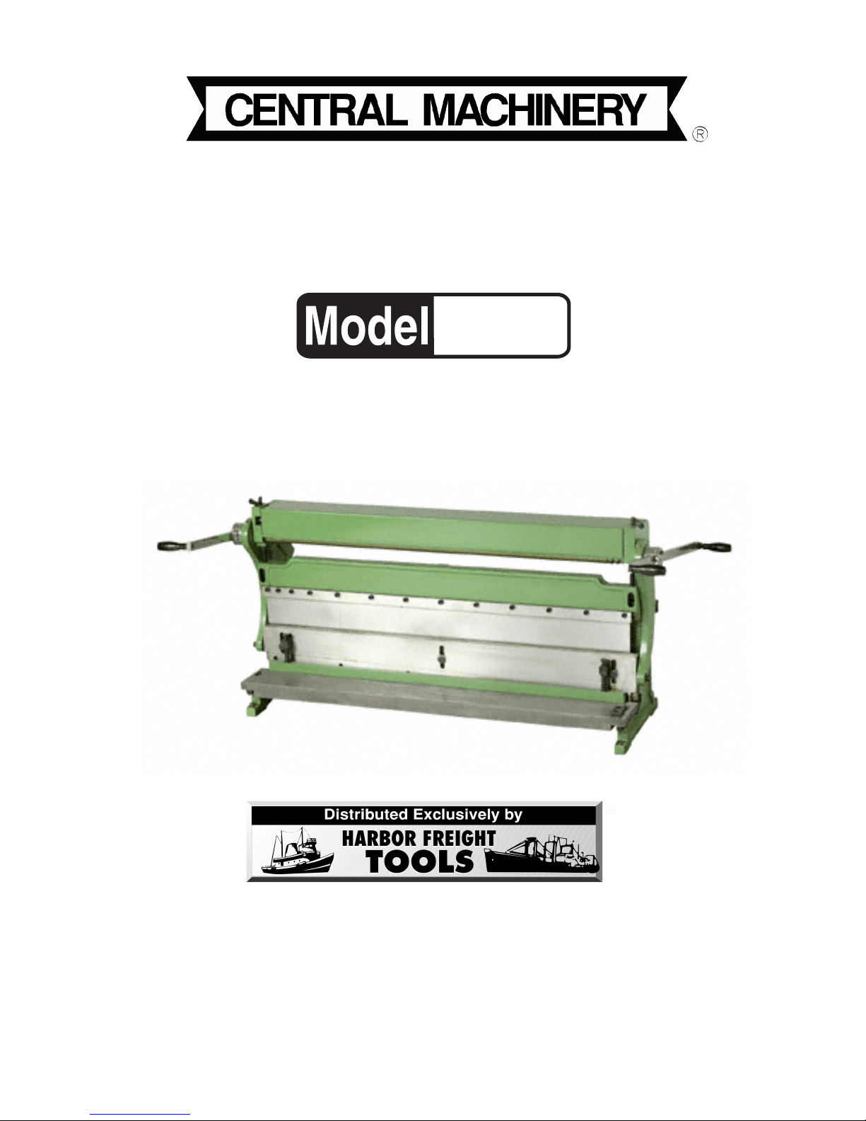
3 IN 1 ROLLER MACHINE
®
40 INCH
43353
ASSEMBLY AND OPERATING
INSTRUCTIONS
3491 Mission Oaks Blvd., Camarillo, CA 93011
Visit our Web site at http://www.harborfreight.com
Copyright © 2000 by Harbor Freight Tools®. All rights reserved. No portion of
this manual or any artwork contained herein may be reproduced in any shape or
form without the express written consent of Harbor Freight Tools.
For technical questions and replacement parts, please call 1-800-444-3353
Revised 01/07
Page 2

Specifications
Item Description
Stock Capacity 40 inches wide; 18 gauge sheet metal
Hold Down Bar 5/8 inch steel
Table Size 42-5/8 (L) x 4-7/8 (W)
Dies 1, 1-1/2, 2, 4, 7, 10, 15 inches
Roller Size 1-21/32 (dia.) x 39 (L) inches
Round Stock Grooves (3 sizes) 1/4, 5/16, 3/8 inches
Handle Dimensions 30 inches
Zerk Fittings Automotive
Overall Dimensions 49 x 15-1/2 x 24 inches
Weight 420 lbs.
Hex Wrenches 5, 6, 8 mm
Save This Manual
You will need the manual for the safety warnings and precautions, assembly instructions,
operating and maintenance procedures, parts list and diagram. Keep your invoice with this
manual. Write the invoice number on the inside of the front cover. Keep the manual and
invoice in a safe and dry place for future reference.
Safety Warnings and Precautions
WARNING: When using tool, basic safety precautions should always be followed to
reduce the risk of personal injury and damage to equipment.
Read all instructions before using this tool!
1. Keep work area clean. Cluttered areas invite injuries.
2. Observe work area conditions. Do not use machines or power tools in damp or wet
locations. Don’t expose to rain. Keep work area well lighted. Do not use electrically
powered tools in the presence of flammable gases or liquids.
3. Keep children away. Children must never be allowed in the work area. Do not let
them handle machines, tools, or extension cords.
4. Store idle equipment. When not in use, tools must be stored in a dry location to
inhibit rust. Always lock up tools and keep out of reach of children.
5. Do not force tool. It will do the job better and more safely at the rate for which it was
intended. Do not use inappropriate attachments in an attempt to exceed the tool
capacity.
6. Use the right tool for the job. Do not attempt to force a small tool or attachment to do
the work of a larger industrial tool. There are certain applications for which this tool
was designed. Do not modify this tool and do not use this tool for a purpose for which
it was not intended.
Page 2SKU 43353
Rev 11/01
Page 3

7. Dress properly. Do not wear loose clothing or jewelry as they can be caught in
moving parts. Protective, electrically non-conductive clothes and non-skid footwear
are recommended when working. Wear restrictive hair covering to contain long hair.
8. Use eye and ear protection. Always wear ANSI approved impact safety goggles.
Wear a full face shield if you are producing metal filings or wood chips. Wear an ANSI
approved dust mask or respirator when working around metal, wood, and chemical
dusts and mists.
9. Do not overreach. Keep proper footing and balance at all times. Do not reach over or
across running machines.
10. Maintain tools with care. Keep tools sharp and clean for better and safer
performance. Follow instructions for lubricating and changing accessories. Inspect tool
cords periodically and, if damaged, have them repaired by an authorized technician.
The handles must be kept clean, dry, and free from oil and grease at all times.
11. Remove adjusting keys and wrenches. Check that keys and adjusting wrenches
are removed from the tool or machine work surface before using.
12. Stay alert. Watch what you are doing, use common sense. Do not operate any tool
when you are tired.
13. Check for damaged parts. Before using any tool, any part that appears damaged
should be carefully checked to determine that it will operate properly and perform its
intended function. Check for alignment and binding of moving parts; any broken parts
or mounting fixtures; and any other condition that may affect proper operation. Any
part that is damaged should be properly repaired or replaced by a qualified
technician.
14. Replacement parts and accessories. When servicing, use only identical
replacement parts. Use of any other parts will void the warranty. Only use accessories
intended for use with this tool. Approved accessories are available from Harbor
Freight Tools.
15. Do not operate tool if under the influence of alcohol or drugs. Read warning
labels on prescriptions to determine if your judgment or reflexes are impaired while
taking drugs. If there is any doubt, do not operate the tool.
16. Maintenance. For your safety, service and maintenance should be performed
regularly by a qualified technician.
Warning: The warnings, cautions, and instructions discussed in this instruction manual
cannot cover all possible conditions and situations that may occur. It must be understood by the operator that common sense and caution are factors which cannot be
built into this product, but must be supplied by the operator.
Page 3SKU 43353
Page 4
Roller Machine Safety Precautions
1. Avoid cuts by always wearing gloves when handling sheet metal.
2. Keeps hands and clothes out of the path of the rollers.
3. The Roller Machine should only be used by an experienced operator.
Unpacking
When unpacking, check to make sure the following parts are included:
- Roller Machine - 7 Dies - 3 Hex Wrenches
If any parts are missing or broken, please call Harbor Freight Tools at the number on the
cover of this manual as soon as possible. Parts of this machine come coated with a rust
inhibitor. It must be removed before using. Refer to the Maintenance section on page 8.
Operation
The Roller Machine is used for shearing and rolling sheet metal up to 18 gauge. The Roller
Machine comes pre-adjusted from the factory. Before using it, however, check that all the
necessary adjustments are made (Refer to the section on Adjustments).
Pressing
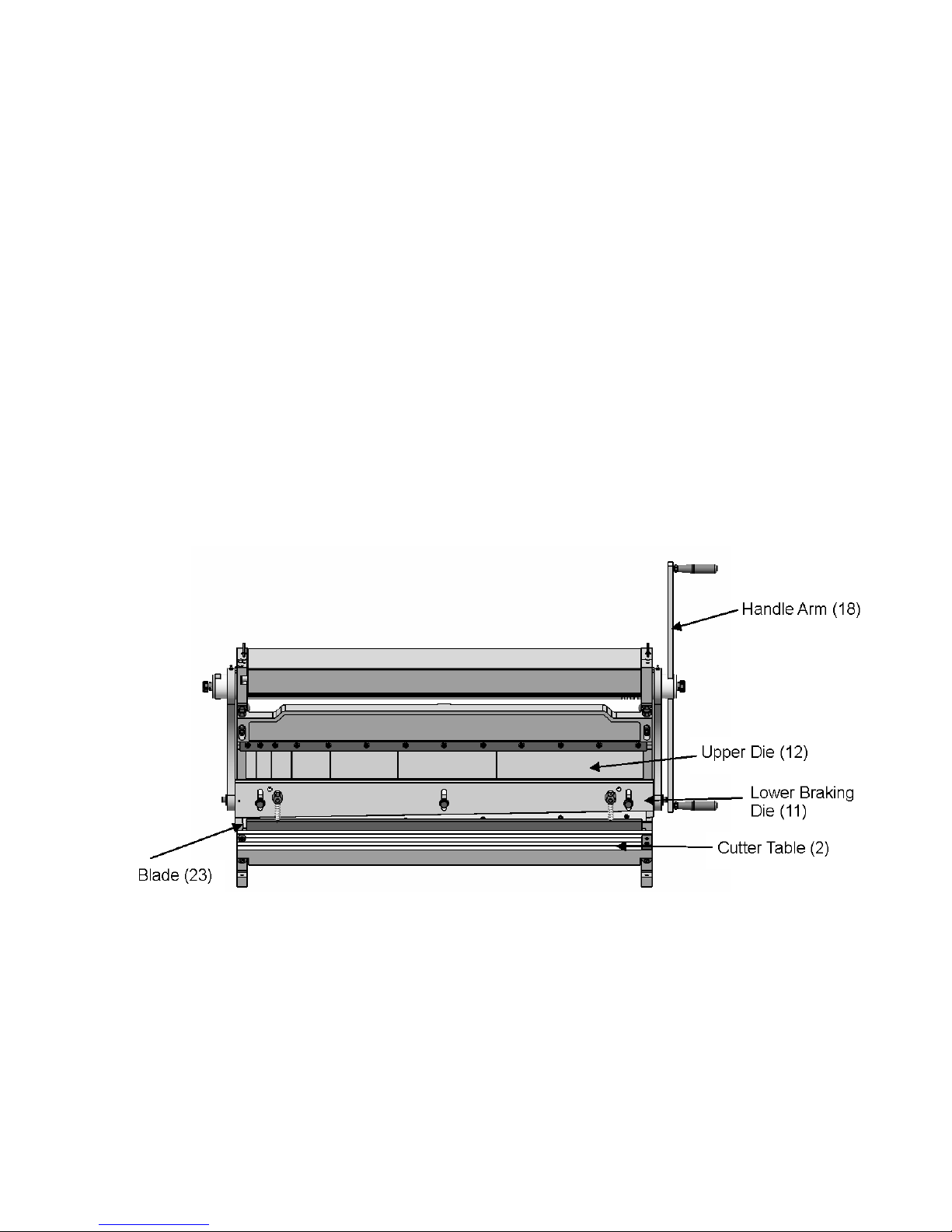
1. Raise the Lower Braking Die (11) to its highest level by rotating the Handle Arm (18).
2. Slide the Press Plate Brackets (8) of the Press Plate Assembly (8,9,10,54) into the
receiver holes of the Lower Braking Die (11).
Note that the Press Plate (10) should be facing down.
3. Raise the Press Plate (10) as necessary by turning the Hex Bolt (54) clockwise.
4. Place the workpiece so that it is centered under the Press Plate (10).
5. Rotate the Handle Arm (18) to press the workpiece.
Page 4SKU 43353
Page 5

Shearing
1. Scribe the cutting mark on the sheet metal.
2. Slide the sheet metal between the upper Blade (23) and the lower Blade (23) so that
the upper Blade (23) is positioned directly over the cutting mark.
If additional cuts of identical size are needed, the Backstop (21) can be adjusted to the
required depth. The sheet metal will stop on the Backstop (21) when inserted. Refer to
the Adjustments section, Adjusting the Backstop.
3. While holding the material steady, rotate the Handle Arm (18) until the material has
been cut.
For large pieces of sheet metal, it may be necessary to use a front table to support the
metal, or have someone hold it for you.
Angle Bending
1. Mark the sheet metal where it is to be bent.
2. Place the sheet metal above the Lower Braking Die (11).
3. Align the bending mark with the front edge of the Upper Die (12).
If multiple bends of identical size and angle sheet metal are needed, the Backstop (21)
can be adjusted to the required depth. The sheet metal will stop on the Backstop (21)
when inserted. Refer to the Adjustments section, Adjusting the Backstop.
4. Rotate the Handle Arm (18) until the desired angle been formed.
Use a protractor or other measuring tool to ensure accuracy.
Radius Bending
Radius bending is most commonly used to make cylinders and cones. Both shapes are
formed by making a series of small, closely spaced bends in the work piece. For cylinders,
the bends are even spaced. For cones, move one side of the sheet metal further out each
time a bend is made.
Pan Bending
The Angle Bending feature can be used to make various sizes of pans out of sheet metal.
The maximum lip (side) height is 1 inch.
1. Pre-measure and cut your material before bending.
Notch the corners to the desired lip (side) height.
2. Place the sheet metal above the Lower Braking Die (11).
3. Align the bending mark with the front edge of the Upper Die (12).
4. Rotate the Handle Arm (18) until 90 degree angle been formed.
Page 5SKU 43353
Page 6

Use a protractor or other measuring tool to ensure accuracy.
5. Rotate the sheet metal 90 degrees counterclockwise.
Allow the completed side to extend just beyond the Dies.
6. Bend the sheet metal. Repeat step 5 for the 3rd side.
7. Rotate to the final side and insert the sheet metal lip between the Dies.
The formed sides will be on the outside of the Dies.
8. Before bending the 4th side, tap one corner nearer the middle of the machine.
This will allow the sides to clear the upper Die (12) when raised.
Rolling
1. Lift the front Cover (33) and flip backward, out of the way.
2. Drop the Rear Roll Bar (24) by loosening the Adjustment Knob (25b).
3. Insert only the leading edge of the sheet metal between the Upper Roll Bar (32) and
the Lower Roll Bar (31), tighten the Adjustment Keys (27) until the Roll Bars are just
snug against the sheet metal.
4. Advance the Adjustable Bolt (25b) to the desired tightness for the roll.
The more the Adjustable Bolt (25b) is advanced, the tighter the roll.
5. Turn the Handle Arm (18) until the desired roll is achieved.
The sheet metal should feed itself through the rollers as the Handle Arm (18) is turned.
Wire Rolling
1. Select the proper size groove in the Upper Roll Bar (32) depending upon the gauge of
the wire being rolled.
2. Follow steps 2 through 5 (above), under Rolling.
Adjustments
While making adjustments, it may be necessary to refer to the Assembly Drawing at the end
of this manual
Handle Removal and Adjustment
The Handle Arm (18) may be adjusted or removed by removing one of the Handle Knob
Assemblies (26a, 26b, 61) and loosening the Knob (59) that holds the Handle Arm (18) in
place. It may then be slid out of the handle socket.
Bending Die Adjustment and Removal
The Upper Die (12) is segmented and can be used for varying sizes of box and pan forming.
When forming a smaller box or pan, choose the desired size Upper Die (12) finger, center it
and remove the others.
Page 6SKU 43353
Page 7

The Roller Machine can be used to bend sheet metal up to 18 gauge. The space between
the Upper Die (12) and the Lower Braking Die (11) is adjustable as described below.
1. Place a piece of flat, straight wood (or metal place) between the Upper Die (12) and
Lower Braking Dies (11) and raise the Lower Braking Die (11) so that the material just
touches the Upper Die (12).
2. Loosen the Hex Head Screws (51) holding the Upper Die (12) in place.
Do not remove the Screws.
3. Remove any unnecessary Upper Die (12) fingers.
4. Raise the Lower Braking Die (11), using the long piece of wood or metal plate as a
level guide, adjust the alignment of the Upper Die (12) fingers.
5. When aligned, retighten the Hex Head Screw (51).
Removal and Installation of the Upper Cutting Blade (23)
1. Remove the six Hex Head Screws (55) holding in the upper cutting Blade (23).
2. Remove (or replace) the upper cutting Blade (23), and replace the Screws but do not
tighten completely.
3. Align the upper cutting Blade (23) so that it is flush with the Lower Braking Die (11).
4. Tighten all the Hex Head Screws (55).
Adjustment of the Upper Cutting Blade
1. Place a 30 inch piece of thin cardboard or paper between the upper and lower Blades
(23).
2. Rotate the Handle Arm (18) and cut the material.
3. Use a straightedge to determine the straightness of the cut and if the Blade (23) is in
need of adjustment.
4. If the Blade (23) is bowed out (away from the front of the machine), turn the adjustment
Nut (48) counterclockwise.
This will tighten the Adjustment Bar (22) and push the middle of the upper Blade (23)
out, while pulling in its ends.
5. If the Blade (23) is bowed in (towards the back of the machine), turn the adjustment Nut
(48) clockwise.
This will loosen the Adjustment Bar (22) and pull the middle of the upper Blade (23) in,
while pushing its ends out.
Removal and Installation of the Lower Blade
1. Remove the Hex Head Screws (57) from the lower cutting Blade (23).
2. Remove (or replace) the lower cutting Blade (23).
Page 7SKU 43353
Page 8

3. Replace the Hex Head Screws (57).
Adjustment of the Lower Cutting Blade (23)
1. Turn the Handle Arm (18) and lower the upper Blade (23) to its lowest position.
2. Loosen the two inset Hex Head Screws (58) located on top of the Cutter Table (2).
3. Adjust the lower cutting Blade (23) by turning its Adjusting Bolts (17).
The distance between the lower and upper cutting Blade (23) should be 5 to 8 percent
of the thickness of the workpiece.
4. Tighten the two inset Hex Head Screws (58) located on top of the Cutter Table (2).
Installation and Adjustment of the Backstop (21)
1. Screw the two Support Rods (19) into the back of the Crossbeam (3).
2. Slide the two Support Blocks (20) onto the Support Rods.
3. Attach the Backstop (21) to the Support Blocks using the Hex Head Screws (42).
- If used for bending, attach the Backstop on top of the Support Blocks.
- If used for shearing, attach the Backstop on the bottom of the Support Blocks.
4. Adjust the Backstop to the desired depth and tighten the Knob (41).
Maintenance
1. Before using this machine, certain parts coated with rust inhibitor must be first cleaned
using varnish thinner.
2. Lubricate the eccentric mechanism daily with machine oil.
3. Periodically check all nuts, bolts, and screws for tightness.
4. Periodically lubricate the rollers surface with a clean rag and machine oil.
5. Place the Cover over the rollers when not in use.
PLEASE READ THE FOLLOWING CAREFULLY
THE MANUFACTURER AND/OR DISTRIBUTOR HAS PROVIDED THE PARTS DIAGRAM IN THIS
MANUAL AS A REFERENCE TOOL ONLY. NEITHER THE MANUFACTURER NOR DISTRIBUTOR
MAKES ANY REPRESENTATION OR WARRANTY OF ANY KIND TO THE BUYER THAT HE OR
SHE IS QUALIFIED TO MAKE ANY REPAIRS TO THE PRODUCT OR THAT HE OR SHE IS
QUALIFIED TO REPLACE ANY PARTS OF THE PRODUCT. IN FACT, THE MANUFACTURER
AND/OR DISTRIBUTOR EXPRESSLY STATES THAT ALL REPAIRS AND PARTS REPLACEMENTS
SHOULD BE UNDERTAKEN BY CERTIFIED AND LICENSED TECHNICIANS AND NOT BY THE
BUYER. THE BUYER ASSUMES ALL RISK AND LIABILITY ARISING OUT OF HIS OR HER
REPAIRS TO THE ORIGINAL PRODUCT OR REPLACEMENT PARTS THERETO, OR ARISING
OUT OF HIS OR HER INSTALLATION OF REPLACEMENT PARTS THERETO.
Page 8SKU 43353
Page 9

Parts List
NOTE: Some parts are listed and shown for illustration purposes only and are not available
individually as replacement parts.
Page 9SKU 43353
Page 10

Page 10SKU 43353
Page 11

WARRANTY
Page 11SKU 43353
 Loading...