

Cellvine LTE700UC26 User Manual

USER MANUAL
BDA-700UC-26-52-AA-MBX-VZW
LTE 700 MHZ
OVER-THE-AIR REPEATER
CELLVINE LTD. BDA-700UC-26-52-AA-MBX-VZW
REVISIONS
Rev Description of Change Revision date Revised by
IMPORTANT NOTICE
This manual contains proprietary information of Cellvine Ltd. No part
of this publication may be reproduced in any form whatsoever without
prior written approval of Cellvine Ltd. Cellvine and/or its agents and
distributors make no claims or warranties concerning the fitness of the
products or documentation for any purpose other than what is
specifically mentioned in this manual.
For more information contact Cellvine at the address below or contact
your local distributor.
© 2010 Cellvine Ltd, all rights reserved Ver.1.3:2010-10
II

CELLVINE LTD. BDA-700UC-26-52-AA-MBX-VZW
YEAR LIMITED HARDWARE AND SOFTWARE WARRANTY
Cellvine Ltd. warrants all repeater Products against electrical malfunction for a
period of One (1) year from shipment of the product to the purchaser. If Cellvine
receives notice of defects during the warranty period, Cellvine will either replace
or repair the products.
WARRANTY EXCLUSIONS AND LIMITATIONS
The warranty shall not apply to defects resulting from improper operation,
inadequate maintenance, or unauthorized use or modification by the customer of
the repeater products or software. The warranty service and service beyond the
warranty period described herein are the customer's sole remedies.
OBTAINING SERVICE DURING AND BEYOND WARRANTY PERIOD
To obtain warranty service, the customer shall return the repeater product to
Cellvine Ltd with date and proof of purchase and an explanation of the problem.
The customer shall pay for shipping charges and Cellvine shall pay for return
shipping. For service beyond the warranty period, contact Cellvine for details of
available service.
GETTING HELP
The repeaters have undergone extensive testing prior to shipment. All of the
functions have been thoroughly tested. However, if there are problems that you
discover, please call us. We are here to help.
ABOUT THIS MANUAL
This user manual is intended for experienced installation technicians and
engineers. It contains the following:
o A general description of the BDA-700UC-26-52-AA-MBX-VZW repeater system
and system components
o Installation overview
o Repeater system operation
© 2010 Cellvine Ltd, all rights reserved Ver.1.3:2010-10
iii
CELLVINE LTD. BDA-700UC-26-52-AA-MBX-VZW
Contacting Cellvine
Headquarter
Cellvine Ltd.
8 Moshe Aviv (Ha'amal) st,
60371Or-Yehuda
ISRAEL
Phone: +972-3634-8881
Fax: +972-3-6348882
markting@cellvine.com
U.S. Office
Cellvine LLC
80 Wesley Street
South Hackensack
NJ 07606
Phone : 201-531-8600
Fax : 201-531-8606
sbalonso@aol.com
© 2010 Cellvine Ltd, all rights reserved Ver.1.3:2010-10
iii

CELLVINE LTD. BDA-700UC-26-52-AA-MBX-VZW
Contents
1. INTRODUCTION .......................................................................1
1.1. General Description..................................................................1
2. SYSTEM COMPONENTS .........................................................2
2.1. BDA-700UC-26-52-AA-MBX-VZW Repeater Kit ..................... 2
2.2. REPEATER UNIT.......................................................................2
2.3. Repeater UNIT RF Specifications ............................................3
2.4. Repeater Block diagram...........................................................4
2.5. Dimensions and Weight ........................................................... 5
2.6. Repeater unit Interfaces...........................................................6
3. INSTALLATION ........................................................................7
3.1. Unpacking and Inspection ....................................................... 7
3.2. Operating Environment............................................................8
3.3. Pre-Installation Inspection.......................................................8
3.4. Antennas Installation................................................................ 8
3.4.1. Coverage (Service) Antennas ..................................................8
3.4.2. DONOR Antenna .......................................................................9
3.5. Repeater unit Mechanical Installation ...................................10
3.5.1. Repeater Installation .............................................................. 10
3.5.2. Power supply Installation....................................................... 12
3.6. Repeater cable connection ....................................................14
© 2010 Cellvine Ltd, all rights reserved Ver.1.3:2010-10
iv

CELLVINE LTD. BDA-700UC-26-52-AA-MBX-VZW
3.7. System INDICATIONS.............................................................15
3.8. Tuning Donor antenna............................................................16
3.9. Antenna Isolation....................................................................16
4. REPEATER MONITORING AND CONTROL ..........................17
4.1. preparing the repeater for local connection .........................17
4.1.1. software application ...............................................................17
4.1.2. System Requirements............................................................17
4.2. Define PC/laptop internet settings......................................... 18
5. SOFTWARE OPERATION......................................................20
5.1. Software Password and unit detailes screen .......................21
5.2. Technician setup screen........................................................ 22
5.2.1. maximum gain limit ................................................................ 24
5.2.2. aGC Power ..............................................................................24
5.2.3. AGC ON/OFF ........................................................................... 25
5.2.3.1. Downlink Gain........................................................................ 25
5.2.3.2. Uplink Gain.............................................................................26
5.2.4. MUTE ON/OFF.........................................................................27
5.2.5. Uplink Downlink delta.............................................................28
5.3. Parameter value readouts...................................................... 29
5.4. Alarm setting screen ..............................................................30
5.4.1. Downlink low Limit Treshold .................................................30
6. SYSTEM ALARMS..................................................................31
© 2010 Cellvine Ltd, all rights reserved Ver.1.3:2010-10
v

CELLVINE LTD. BDA-700UC-26-52-AA-MBX-VZW
6.1. LED indication panel ..............................................................32
6.2. Downlink High......................................................................... 33
6.3. Downlink Low .........................................................................33
6.4. UPLINK HIGH ..........................................................................35
6.5. Power Amplifier shutdown protections.................................36
7. TROUBLESHOOTING ............................................................37
7.1. Connection Failure .................................................................37
7.2. GUI Parameters not update correctly....................................37
© 2010 Cellvine Ltd, all rights reserved Ver.1.3:2010-10
vi

CELLVINE LTD. BDA-700UC-26-52-AA-MBX-VZW
Figures
Figure 1-1: BDA-700UC-26-52-AA-MBX-VZW Repeater.............................1
Figure 2-1: System Block Diagram.................................................................4
Figure 2-2: Repeater dimensions.................................................................5
Figure 3-1: Cable Connections.....................................................................14
Figure 3-2: Repeater Indications LED's........................................................15
© 2010 Cellvine Ltd, all rights reserved Ver.1.3:2010-10
vii

CELLVINE LTD. BDA-700UC-26-52-AA-MBX-VZW
Abbreviations
The terms, acronyms and abbreviations used in this manual are detailed
in the following list:
Abréviation Description
AGC Automatic Gain Control
BDA Bi Directional amplifier
BL Bluetooth
Div Diversity
DU Donor Antenna Unit
LED Light Emitting Diode
LNA Low Noise Amplifier
NMS Network Management System
PA Power Amplifier
PSU Power Supply Unit
REP Repeater
RF Radio Frequency
RSSI Received Signal Strength Indication
RU Remote Unit
RX Receiver
SC Service Channel
TX Transceiver unit
© 2010 Cellvine Ltd, all rights reserved Ver.1.3:2010-10
viii

CELLVINE LTD. BDA-700UC-26-52-AA-MBX-VZW
General Safety Warning
Always observe standard safety precautions during installation, operation
and maintenance of this product. Only qualified and authorized personnel
should carry out adjustment, maintenance or repairs to the components of
this system.
DANGER: ELECTRICAL SHOCK
The power supply unit contains dangerous voltage that can cause electric
shock. Disconnect the mains prior to any work in the Repeater. Any local
regulations are to be followed when servicing Repeaters.
This equipment is usually installed indoors. Wet conditions increase the
potential for receiving an electric shock when installing or using
electrically powered equipment. To prevent electrical shock when
installing or modifying the system power wiring, disconnect the wiring at
the power source before working with insinuated wires or terminals.
Repeaters supplied from the mains must be connected to grounded outlets
and in conformity with any local regulations.
CAUTION: HIGH GROUND
When working on a Repeater on high ground, e.g. on a mast or pole, be
careful not to drop parts or the entire Repeater. Falling parts can cause
serious personal injury.
CAUTION: COAX CABLE BENDING
Allow sufficient coax cable length to permit routing of patch cords or
pigtails without severe bends.
CAUTION: RADIATION
Any Repeater, including this Repeater, will generate radio signals and
thereby give rise to electromagnetic fields that may be hazardous to the
health of any person who is extensively exposed to the signals at the
immediate proximity of the Repeater and the Repeater antennas.
© 2010 Cellvine Ltd, all rights reserved Ver.1.3:2010-10
ix
CELLVINE LTD. BDA-700UC-26-52-AA-MBX-VZW
CAUTION: STATIC ELECTRICITY
Static electricity means no risk of personal injury but it can severely
damage essential parts of the Repeater, if not handled carefully.
Parts on the printed circuit board as well as other parts in the Repeater
are sensitive to electrostatic discharge.
Never touch the printed circuit board or uninsulated conductor surfaces
unless absolutely necessary.
If you must handle the printed circuit board or uninsulated conductor
surfaces, use ESD protective equipment, or first touch the Repeater
chassis with your hand and then do not move your feet on the floor.
Never let your clothes touch printed circuit boards or uninsulated
conductor surfaces.
Always, store printed circuit boards in ESD-safe bags.
FCC STATEMENT
This equipment has been tested and found to comply with the limits for a
Class A digital device, pursuant to part 15 of the FCC Rules. These limits
are designed to provide reasonable protection against harmful
interference when the equipment is operated in a commercial
environment. This equipment generates, uses, and can radiate radio
frequency energy and, if not installed and used in accordance with the
instruction manual, may cause harmful interference to radio
communications. Operation of this equipment in a residential area is
likely to cause harmful interference, in which case the user will be
required to correct the interference at his expense. Changes or
modifications not expressly approved by the party responsible for
compliance could void the user’s authority to operate the equipment.
RF exposure warning! In order to comply with FCC RF exposure
regulations, you must ensure that the donor antenna is installed at a
minimum distance of 0.2 m (7.8 inches) from persons who may be
present in the area.
© 2010 Cellvine Ltd, all rights reserved Ver.1.3:2010-10
x
CELLVINE LTD. BDA-700UC-26-52-AA-MBX-VZW
1. Introduction
1.1. GENERAL DESCRIPTION
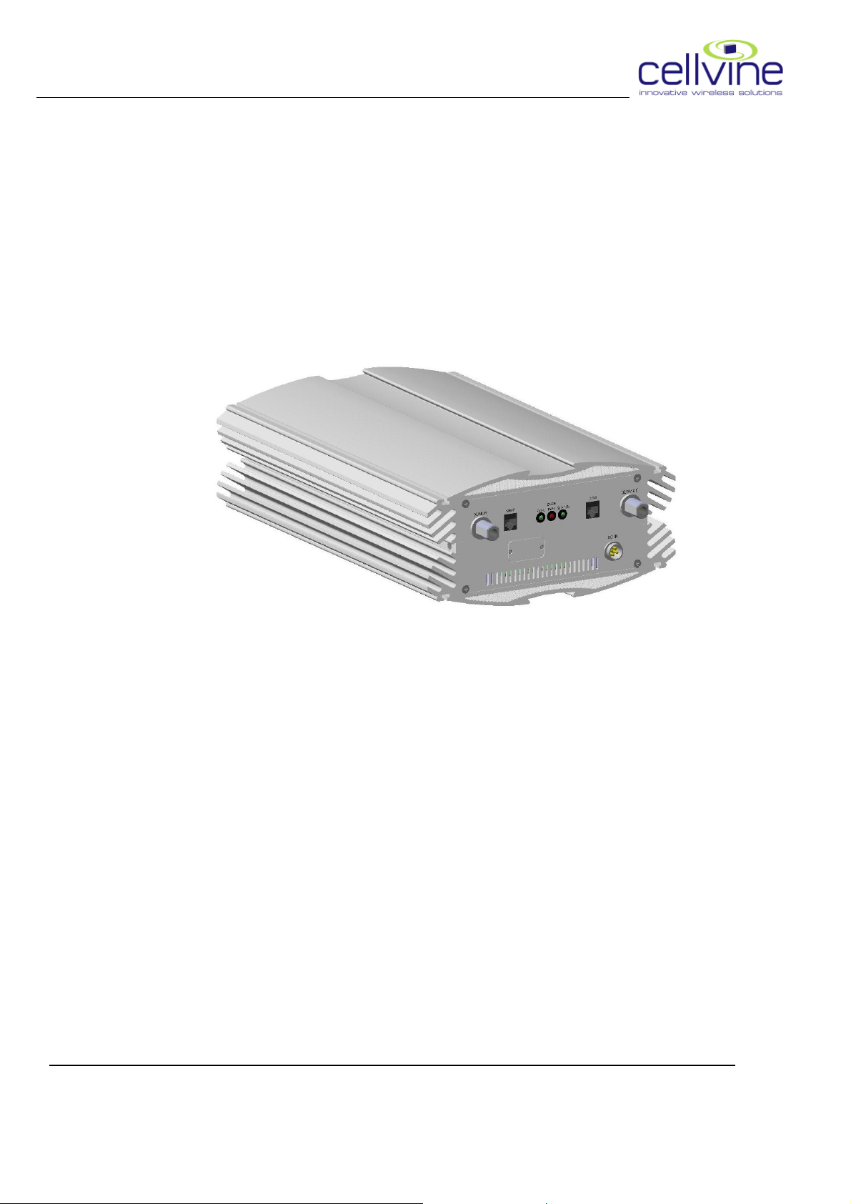
The goal of the Repeater system is to improve coverage for Verizon Wireless
LTE (747– 757 MHz, 777– 787 MHz) in medium size indoor areas
Figure 1-1: BDA-700UC-26-52-AA-MBX-VZW Repeater
The system implements BDA technology to enhance coverage in urban
areas. Repeaters are used to fill out uncovered areas in cellular mobile
systems, such as base station fringe areas, road tunnels, business and
industrial buildings, etc. A Repeater receives signals from a base station,
amplifies the signals and retransmits them to service area. It also receives,
amplifies and retransmits signals in the opposite direction. Both directions
are served simultaneously.
In order to receive and transmit signals in both directions, the Repeater is
connected to a donor antenna directed towards the base station and to a
service antenna directed towards the area to be covered.
Control of the Repeaters is performed using a desktop or laptop computer
equipped with standard browser (no special software) which can
communicate with the Repeaters, either locally or remotely via modem
(optional).
© 2010 Cellvine Ltd, all rights reserved Ver.1.3:2010-10
1

CELLVINE LTD. BDA-700UC-26-52-AA-MBX-VZW
2. System components
2.1. BDA-700UC-26-52-AA-MBX-VZW REPEATER KIT
o Power Supply
o Ethernet CAT 5 cable for Operation and Maintenance of the unit using
a PC .
o Repeater unit
o Wall mounting
o Power supply optional installation kit
o Cross Band Coupler for LTE & Cell / PCS (optional as external or
internal)
o This manual
2.2. REPEATER UNIT
Cellvine’s indoor BDA-700UC-26-52-AA-MBX-VZW Repeater has been
designed to enhance and extend cellular coverage into small and mediumsize buildings, restaurants, underground areas, office buildings and other
similar indoor environments. It provides the following functionalities:
• High linearity and low noise amplifiers
• Telco grade reliability
• High gain + 90dB
• Advanced AGC
• Oscillation detection and protection
• Output power +26 dBm Downlink, +18dBm Uplink
• Full local and remote control and diagnostics
• Available communication through Ethernet protocol
• Optional cellular modem for remote monitoring and control
• integrated or external Cross Band Coupler for LTE & CELL/ PCS
band's
© 2010 Cellvine Ltd, all rights reserved Ver.1.3:2010-10
2
CELLVINE LTD. BDA-700UC-26-52-AA-MBX-VZW
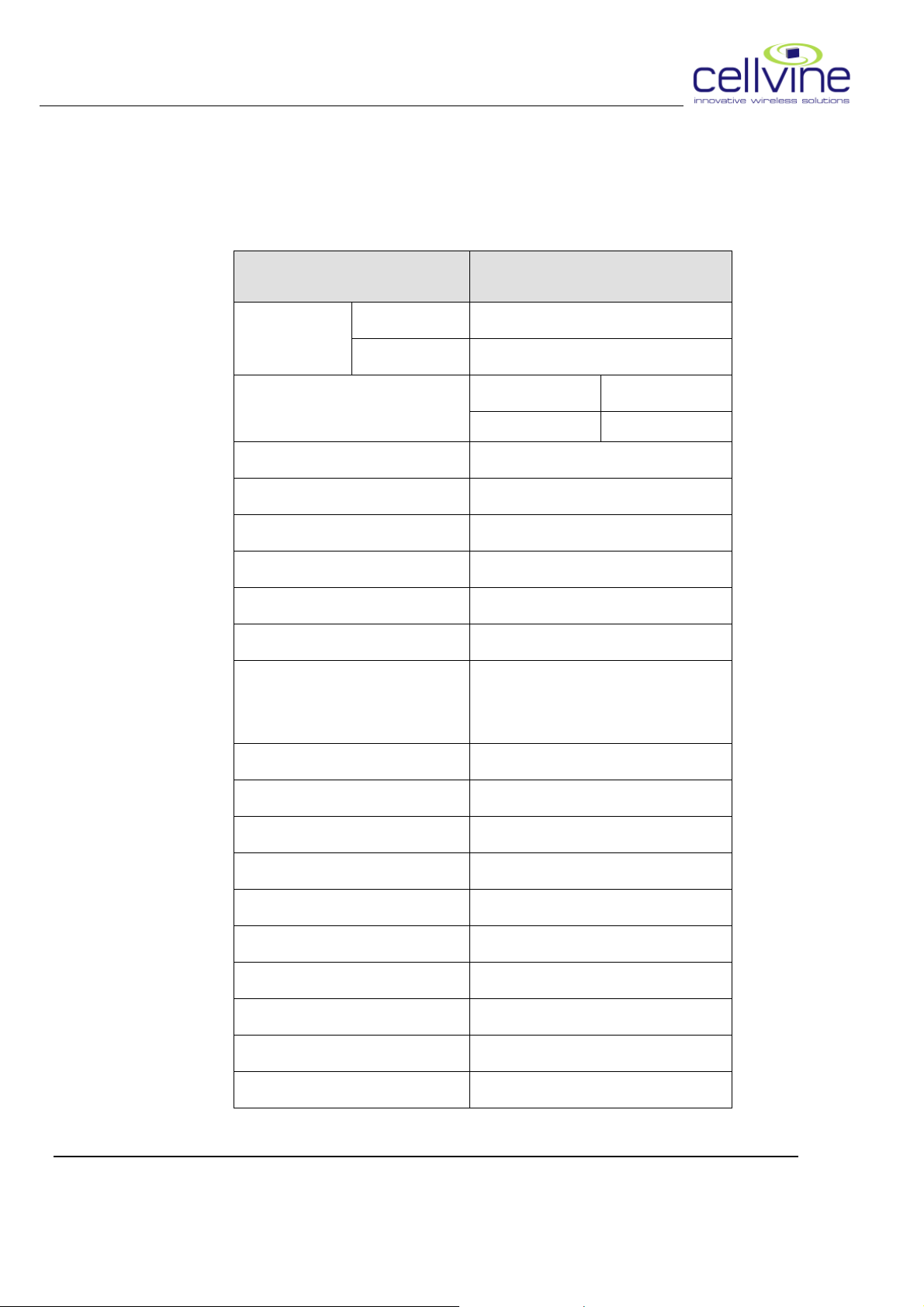
2.3. REPEATER UNIT RF SPECIFICATIONS
Parameters Specifications
DL 747 – 757 MHz (10 MHz LTE)
700 MHz
UL 777 – 787 MHz (10 MHz LTE)
Composite output power
Pass band Ripple ± 2 dB
Max gain DL,UL 90 dB
UL Noise Figure <5dB (at Max gain)
Filtering Meets or exceeds FCC
Out of band Spurious Meets or exceeds FCC
Out of Band Gain Meets or exceeds FCC
EVM
AGC Range 30 dB
Manual Gain control 30 dB in 1 dB steps via software
VSWR <1.5:1
DL UL
26 dBm 18dBm
DL-8-12.5% ,UL-12.5-17.5% According to
VZW 3G&4G Requirements-Rev 2.0 Nov
5/09
Delay <5 usec
Max Safe Input Power -20 dBm
Operating Temp -5C to +50C
Storage Temp -30C to +80C
Sealing Indoor enclosure IP-50
Dimension 16 X 10.5 X 5 inches
Weight <20 Lbs
© 2010 Cellvine Ltd, all rights reserved Ver.1.3:2010-10
3
CELLVINE LTD. BDA-700UC-26-52-AA-MBX-VZW
Parameters Specifications
Power
RF Connectors 2x Type N Female
Modem Connector 1x Type N F emale
M&C connector 1x RJ-45
10 VDC,< 60 W by included 115VAC
power supply.
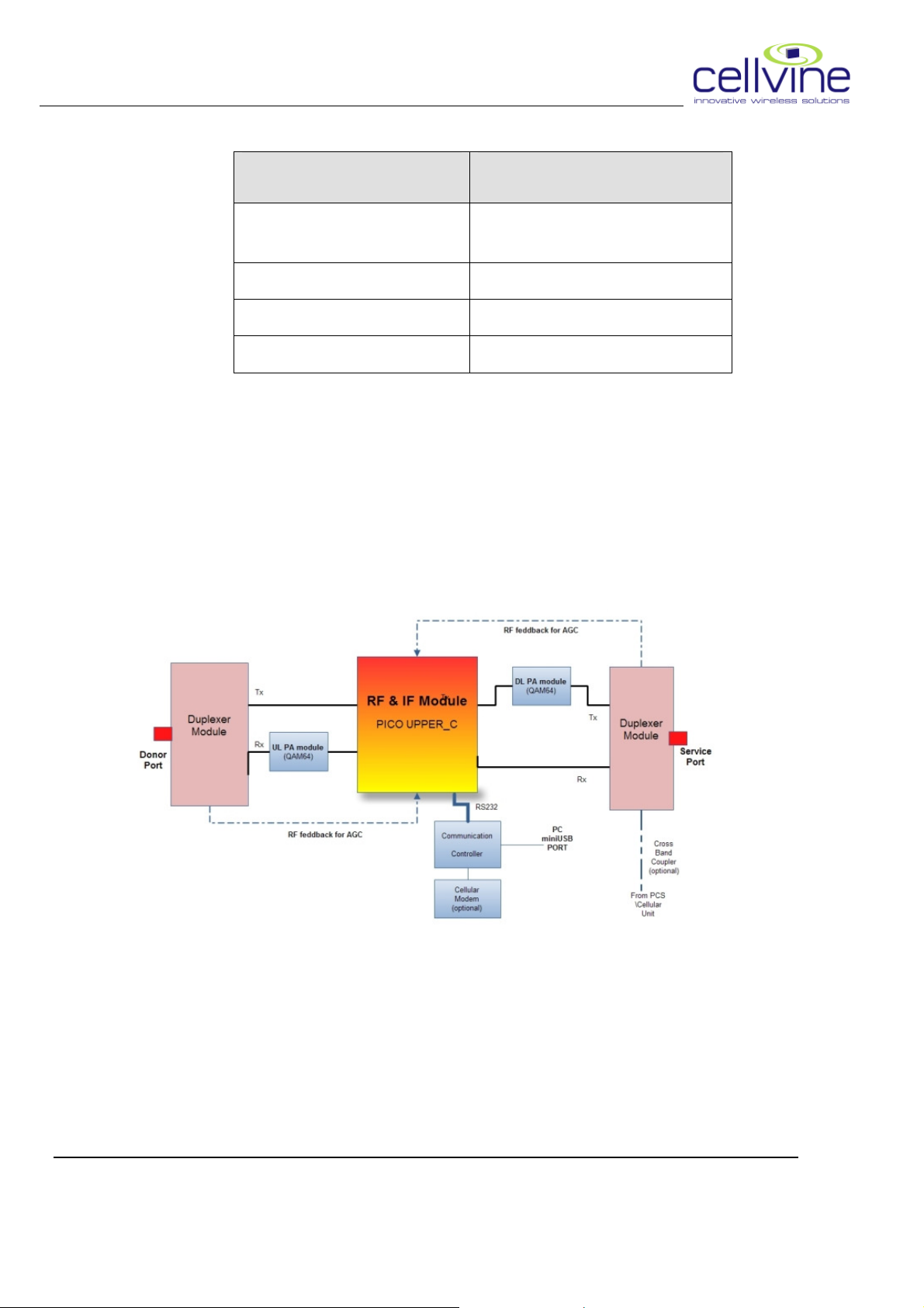
2.4. REPEATER BLOCK DIAGRAM
Figure 2-1: System Block Diagram
© 2010 Cellvine Ltd, all rights reserved Ver.1.3:2010-10
4
 Loading...