

Page 1
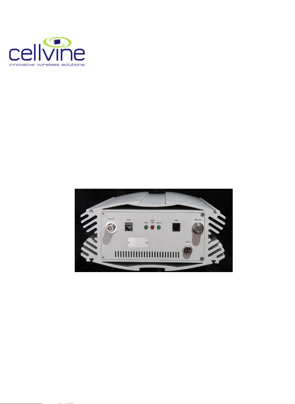
USER MANUAL
BDA-AWS21-26-4UT-AB-JXX
OVER-THE –AIR REPEATER
VER. 1.06
Page 2

CELLVINE LTD. BDA-AWS21-26-4UT-AB-JXX
Important Notice
This manual contains information that is proprietary to
Cellvine Ltd. No part of this publication may be
reproduced in any form whatsoever without prior
written approval by Cellvine Ltd.
No representation or warranties for fitness for any
purpose other than what is specifically mentioned in
this manual is made either by Cellvine or its agents.
For further information contact Cellvine at the address
below or contact your local distributor.
BDA-AWS21-26-4UT-AB-JXX Rev 1.06 2009-05
Page 3

CELLVINE LTD. BDA-AWS21-26-4UT-AB-JXX
BDA-AWS21
-26-
4UT-AB-JXX
Rev
1.06 2009-05
1-YEAR LIMITED HARDWARE
AND SOFTWARE WARRANTY
Cellvine Ltd. warrants all Repeater
Products against electrical
malfunction for a period of One (1)
year from shipment of the product to
the purchaser. If Cellvine receives
notice of defects during the warranty
period, Cellvine will either replace or
repair the products.
WARRANTY EXCLUSIONS AND
LIMITATIONS
The warranty shall not apply to
defects resulting from improper
operation, inadequate maintenance,
or unauthorized use or modification
by the customer of the Repeater
products or software. The warranty
service and service beyond the
warranty period described herein
are the customer's sole remedies.
OBTAINING SERVICE DURING
AND BEYOND WARRANTY
PERIOD
To obtain warranty service, the
customer shall return the Repeater
product to Cellvine Ltd with date
and proof of purchase and an
explanation of the problem. The
customer shall pay for shipping
charges and Cellvine shall pay for
return shipping. For service beyond
the warranty period, contact
Cellvine for details of available
service.
GETTING HELP
The Repeaters have undergone
extensive testing prior to shipment.
All of the functions have been
thoroughly tested. However, if there
are problems that you discover,
please call us. We are here to help.
Page 4
CELLVINE LTD. BDA-AWS21-26-4UT-AB-JXX
Contacting Cellvine
Headquarter
Cellvine Ltd.
Phone: +972-3634-8881
Fax: +972-3-6348882
U.S. Office
55 Madison Ave , Suite 400
Morristown , NJ 07960
Phone : 973-285-3201
Fax : 973-538-0503
[email protected]
BDA-AWS21-26-4UT-AB-JXX Rev 1.06 2009-05
Page 5

CELLVINE LTD. BDA-AWS21-26-4UT-AB-JXX
About this Manual
This User’s Manual is intended for experienced installation technicians
and engineers.
It contains the following:
• A general description of the BDA-AWS21-26-4UT-AB-JXX
Repeater system and system components
• Installation overview
• Repeater system operation
BDA-AWS21-26-4UT-AB-JXX Rev 1.06 2009-05
Page 6

CELLVINE LTD. BDA-AWS21-26-4UT-AB-JXX
Contents
1. INTRODUCTION................................................................1
1.1. General Description..........................................................1
2. SYSTEM COMPONENTS..................................................2
2.1. BDA-AWS21-26-4UT-AB-JXX Repeater Kit .....................2
2.2 REPEATER UNIT ............................................................... 2
2.3 Repeater UNIT RF Specifications .................................... 3
2.4 Repeater Block diagram................................................... 4
2.5 Repeater UNIT Pass-band Filters .................................... 5
2.6 Dimensions and Weight ................................................... 6
2.7 Repeater unit Interfaces ................................................... 6
3. INSTALLATION.................................................................7
3.1 Unpacking and Inspection ............................................... 7
3.2 Operating Environment .................................................... 8
3.3 Pre-Installation Inspection ............................................... 8
3.4 Antennas Installation........................................................ 8
3.5 Repeater unit Mechanical Installation........................... 10
3.6 Repeater cable connection ............................................ 15
BDA-AWS21-26-4UT-AB-JXX Rev 1.06 2009-05
3.7 System INDICATIONS..................................................... 16
3.8 Tuning Donor antenna.................................................... 17
3.9 Antenna Isolation............................................................ 17
Page 7

CELLVINE LTD. BDA-AWS21-26-4UT-AB-JXX
4 REPEATER MONITORING AND CONTROL..................18
4.1 preparing the repeater for local connection ................. 18
4.2 repeater monitoring and control.................................... 22
4.3 preparing the repeater for remote connection via
intRAnet:......................................................................... 31
5 TROUBLESHOOTING.....................................................32
BDA-AWS21-26-4UT-AB-JXX Rev 1.06 2009-05
Page 8

CELLVINE LTD. BDA-AWS21-26-4UT-AB-JXX
Figures
Figure 1-1: BDA-AWS21-26-4UT-AB-JXX Repeater ...................................1
Figure 2-1: System Block Diagram .............................................................4
Figure 2-2: Repeater dimensions................................................................6
Figure 3-1: Repeater Installation............................... האיגש !תרדגומ הניא הינמיסה.
Figure 3-2: Cable Connections ................................................................. 15
Figure 3-3: Repeater Indications LEDs..................................................... 16
BDA-AWS21-26-4UT-AB-JXX Rev 1.06 2009-05
Page 9

CELLVINE LTD. BDA-AWS21-26-4UT-AB-JXX
Abbreviations
The terms, acronyms and abbreviations used in this manual are detailed
in the following list:
Abréviation Description
AGC Automatic Gain Control
BDA Bi Directional amplifier
BL Bluetooth
Div Diversity
DU Donor Antenna Unit
LED Light Emitting Diode
LNA Low Noise Amplifier
NMS Network Management System
PA Power Amplifier
PSU Power Supply Unit
REP Repeater
RF Radio Frequency
RSSI Received Signal Strength Indication
RU Remote Unit
RX Receiver
SC Service Channel
TX Transceiver unit
BDA-AWS21-26-4UT-AB-JXX Rev 1.06 2009-05
Page 10

CELLVINE LTD. BDA-AWS21-26-4UT-AB-JXX
General Safety Warning
Always observe standard safety precautions during installation, operation
and maintenance of this product. Only qualified and authorized personnel
should carry out adjustment, maintenance or repairs to the components of
this system.
DANGER: ELECTRICAL SHOCK
The power supply unit contains dangerous voltage that can cause electric
shock. Disconnect the mains prior to any work in the Repeater. Any local
regulations are to be followed when servicing Repeaters.
This equipment is usually installed indoors. Wet conditions increase the
potential for receiving an electric shock when installing or using
electrically powered equipment. To prevent electrical shock when
installing or modifying the system power wiring, disconnect the wiring at
the power source before working with insinuated wires or terminals.
Repeaters supplied from the mains must be connected to grounded outlets
and in conformity with any local regulations.
CAUTION: HIGH GROUND
When working on a Repeater on high ground, e.g. on a mast or pole, be
careful not to drop parts or the entire Repeater. Falling parts can cause
serious personal injury.
CAUTION: COAX CABLE BENDING
Allow sufficient coax cable length to permit routing of patch cords or
pigtails without severe bends.
CAUTION: RADIATION
Any Repeater, including this Repeater, will generate radio signals and
thereby give rise to electromagnetic fields that may be hazardous to the
health of any person who is extensively exposed to the signals at the
immediate proximity of the Repeater and the Repeater antennas.
BDA-AWS21-26-4UT-AB-JXX Rev 1.06 2009-05
Page 11
CELLVINE LTD. BDA-AWS21-26-4UT-AB-JXX
CAUTION: STATIC ELECTRICITY
Static electricity means no risk of personal injury but it can severely
damage essential parts of the Repeater, if not handled carefully.
Parts on the printed circuit board as well as other parts in the Repeater
are sensitive to electrostatic discharge.
Never touch the printed circuit board or uninsulated conductor surfaces
unless absolutely necessary.
If you must handle the printed circuit board or uninsulated conductor
surfaces, use ESD protective equipment, or first touch the Repeater
chassis with your hand and then do not move your feet on the floor.
Never let your clothes touch printed circuit boards or uninsulated
conductor surfaces.
Always, store printed circuit boards in ESD-safe bags.
FCC STATEMENT
This equipment has been tested and found to comply with the limits for a
Class A digital device, pursuant to part 15 of the FCC Rules. These limits
are designed to provide reasonable protection against harmful
interference when the equipment is operated in a commercial
environment. This equipment generates, uses, and can radiate radio
frequency energy and, if not installed and used in accordance with the
instruction manual, may cause harmful interference to radio
communications. Operation of this equipment in a residential area is
likely to cause harmful interference, in which case the user will be
required to correct the interference at his expense. Changes or
modifications not expressly approved by the party responsible for
compliance could void the user’s authority to operate the equipment.
BDA-AWS21-26-4UT-AB-JXX Rev 1.06 2009-05
Page 12
CELLVINE LTD. BDA-AWS21-26-4UT-AB-JXX
1. Introduction
1.1. GENERAL DESCRIPTION
The goal of the Repeater system is to improve coverage for T-MOBILE AWS
(1710-1755MHz, 2110-2155 MHz) in medium size indoor areas of up to
50,000 sq. ft.
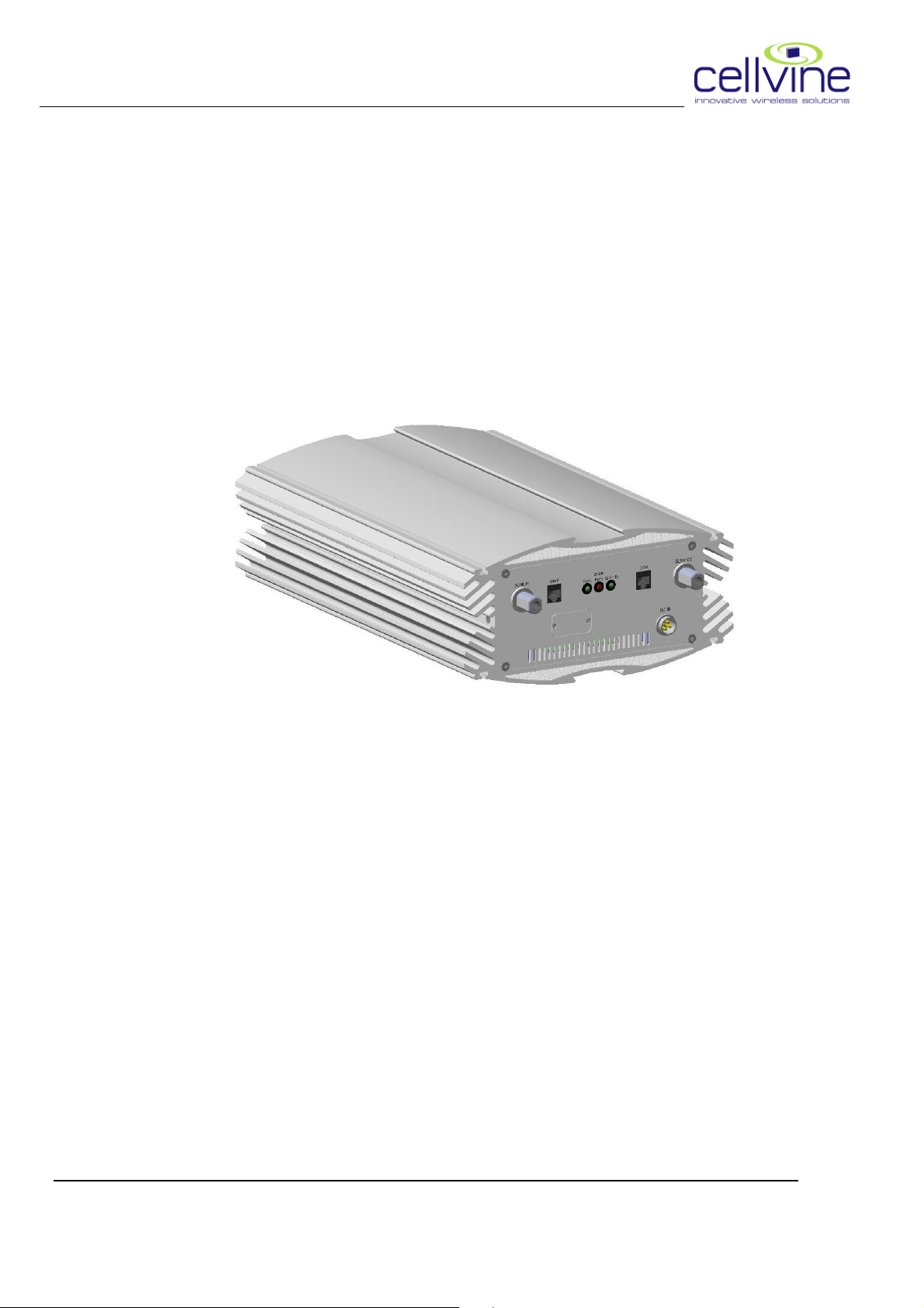
Figure 1-1: BDA-AWS21-26-4UT-AB-JXX Repeater
The system implements BDA technology to enhance coverage in urban
areas. Repeaters are used to fill out uncovered areas in cellular mobile
systems, such as base station fringe areas, road tunnels, business and
industrial buildings, etc. A Repeater receives signals from a base station,
amplifies the signals and retransmits them to service area. It also receives,
amplifies and retransmits signals in the opposite direction. Both directions
are served simultaneously.
In order to receive and transmit signals in both directions, the Repeater is
connected to a donor antenna directed towards the base station and to a
service antenna directed towards the area to be covered.
Control of the Repeaters is performed using a desktop or laptop computer
equipped with standard browser (no special software) which can
communicate with the Repeaters, either locally or remotely via modem
(optional).
BDA-AWS21-26-4UT-AB-JXX Rev 1.06 2009-05
1
Page 13

CELLVINE LTD. BDA-AWS21-26-4UT-AB-JXX
2. System components
2.1. BDA-AWS21-26-4UT-AB-JXX REPEATER
KIT
1. Power Supply
2. Ethernet CAT5E cable for Operation and Maintenance of the unit
using a PC .
3. Repeater unit
4. Wall mounting
5. Power supply optional installation kit
6. This manual
2.2 REPEATER UNIT
Cellvine’s indoor BDA
to enhance and extend cellular coverage into small and medium-size
buildings, restaurants, underground areas, office buildings and other
similar indoor environments. It provides the following functionalities:
• High linearity and low noise amplifiers
• Telco grade reliability
• High gain AWS +80dB
• Advanced AGC
• Oscillation detection and protection
• Output power +26 dBm Downlink, 18dBm Uplink
• Full local and remote control and diagnostics
• Available communication through Ethernet protocol
BDA----AWS21
AWS21----26
BDABDA
AWS21AWS21
26----4UT
4UT----AB
2626
4UT4UT
AB----JXX
JXX Repeater has been designed
ABAB
JXXJXX
• cellular modem for remote monitoring and control
• Adjustable filters for various T-MOBILE AWS sub bands
BDA-AWS21-26-4UT-AB-JXX Rev 1.06 2009-05
2
Page 14

CELLVINE LTD. BDA-AWS21-26-4UT-AB-JXX
2.3 REPEATER UNIT RF SPECIFICATIONS
Parameters Specifications
Frequency Range (Down / Up) See AWS BANDS table below
Output Power DL: 26 dBm
UL: 18 dBm
System Max Gain 80dB +/-2dB
Delay Less then 5usec
Waveform EVM<12%
Ripple +/-2dB
Noise Figure <7dB
Filter rejection >-40dBc @1Mhz from corner frequency
Gain tuning range 30dB in 1dB steps
VSWR 1.5:1
Operating Temperature Standard: -20C to + 60C.
Manual Indicators\Controls See below
Alarms See below
Dimension 16X 10.5X 5 (inches)
Power Requirements 10VDC,<80W from external power supply
(included)
RF Connector N Type female
BDA-AWS21-26-4UT-AB-JXX Rev 1.06 2009-05
3
Page 15
CELLVINE LTD. BDA-AWS21-26-4UT-AB-JXX
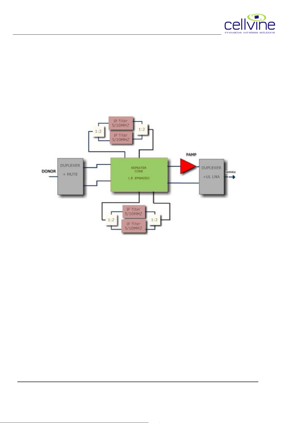
2.4 REPEATER BLOCK DIAGRAM
Figure 2-1: System Block Diagram
BDA-AWS21-26-4UT-AB-JXX Rev 1.06 2009-05
4
Page 16
CELLVINE LTD. BDA-AWS21-26-4UT-AB-JXX
2.5 REPEATER UNIT PASS-BAND FILTERS
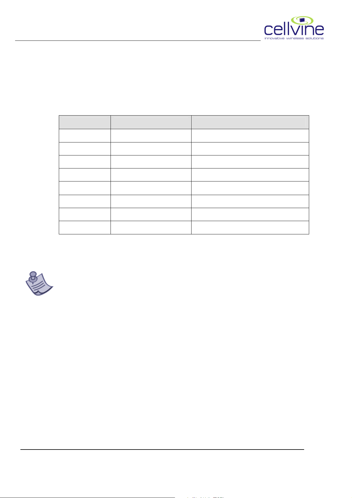
The BDA-AWS21-26-4UT-AB-JXX Repeater unit supports simultaneously
and independently, two of the following sub band options:
REPEATER SUB BAND OPTIONS
Configuration Uplink [MHz] Downlink [MHz]
A 1710-1720 2110-2120
B 1720-1730 2120-2130
C 1730-1735 2130-2135
D 1735-1740 2135-2140
E 1740-1745 2140-2145
F 1745-1755 2145-2155
C+D 1730-1740 2130-2140
D+E 1735-1745 2135-2145
NOTE
The system can be configured to one or two sub bands from the above list
of BW 5 or 10 MHz. Any filter can be turned off, if needed
BDA-AWS21-26-4UT-AB-JXX Rev 1.06 2009-05
5
Page 17
CELLVINE LTD. BDA-AWS21-26-4UT-AB-JXX
2.6 DIMENSIONS AND WEIGHT
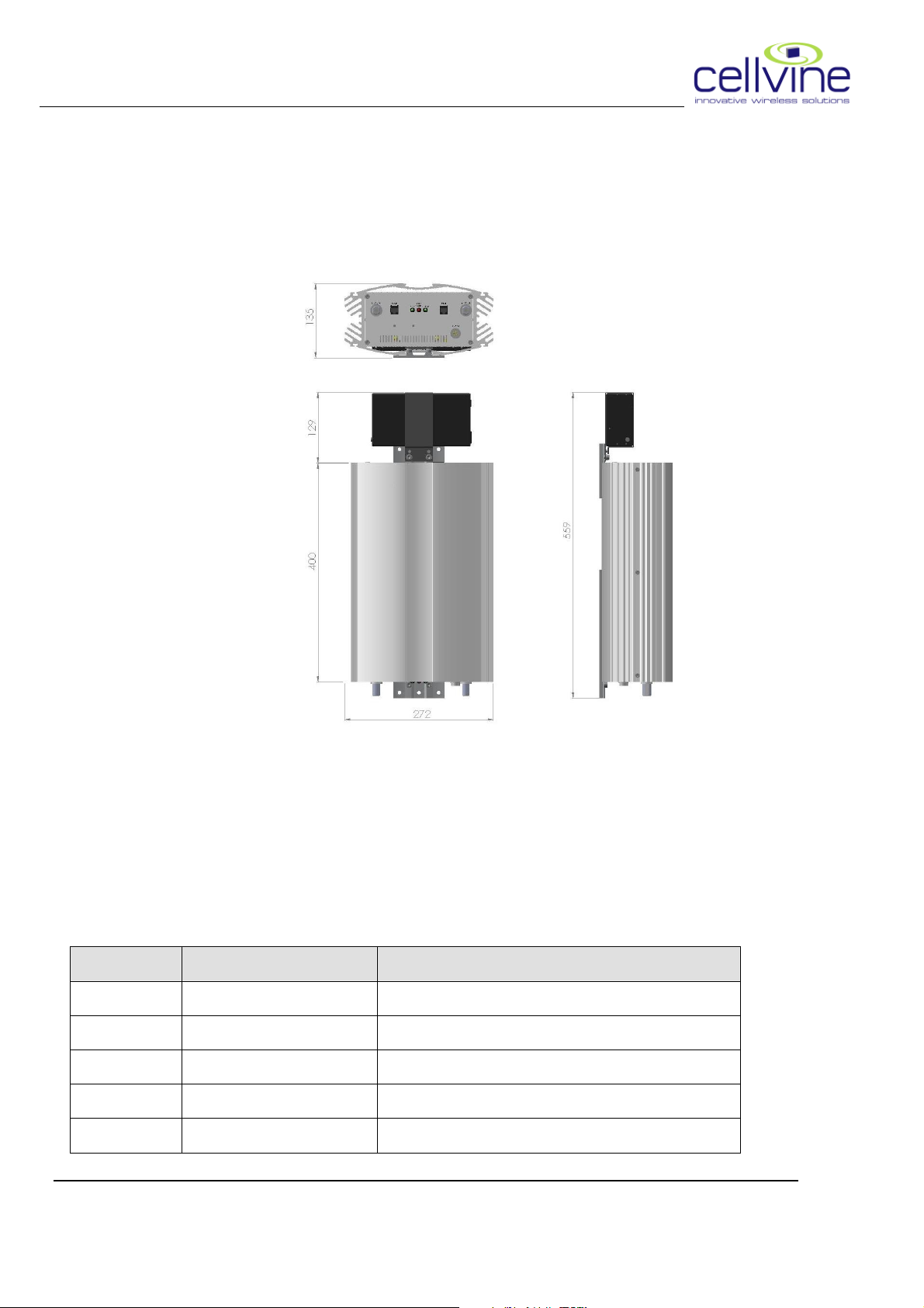
The dimension of the Repeater, including the mounting bracket, is shown in
Figure2-2.
Figure 2-2: Repeater dimensions
Approximate Repeater weight: 12 Kg (26 lbs)
2.7 REPEATER UNIT INTERFACES
The Repeaters interfaces are located at the bottom, op and the side of the
Repeater.
Table 2-1 :
Name Type Function
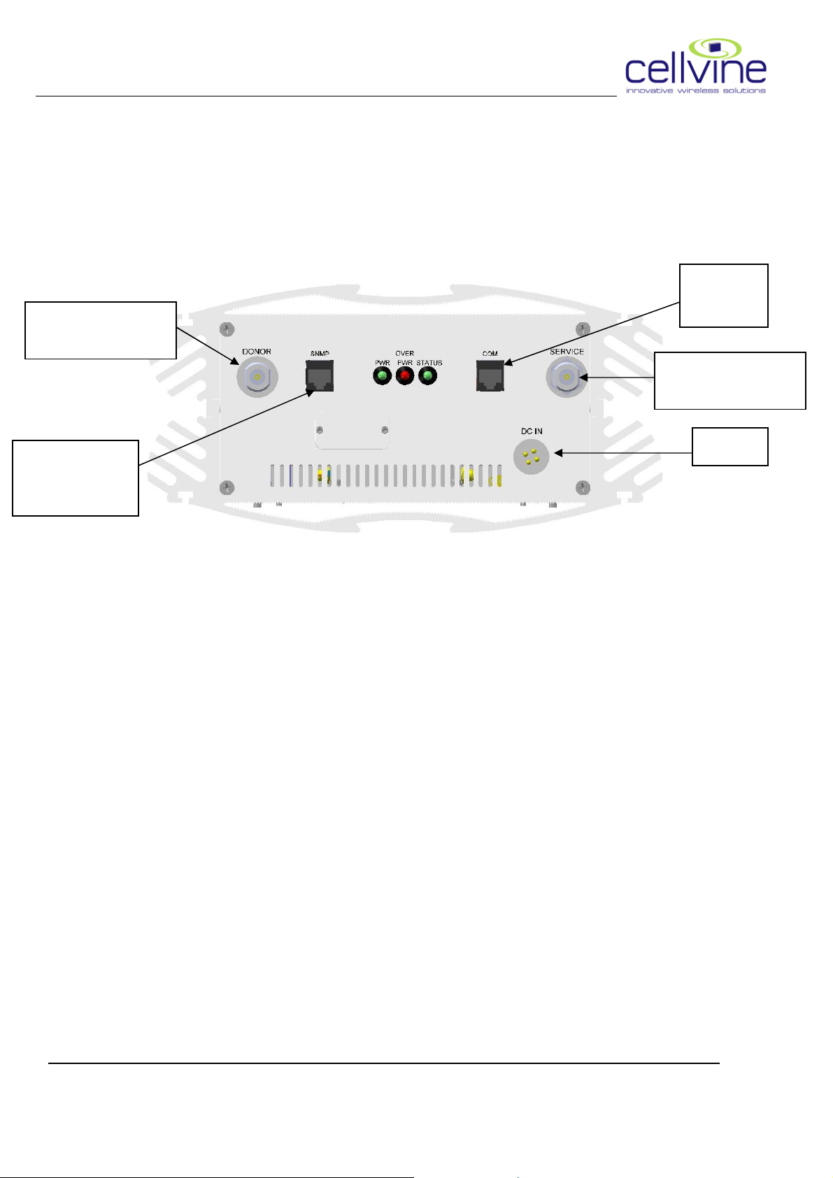
SERVICE N-Type female connector Connect to Service antenna
DONOR N-Type female connector Connect to Donor antenna
POWER PLT DC connector Connect to Power supply
COM RJ 45 Ethernet connection to PC
SNMP RJ 45 Ethernet connection to LAN
BDA-AWS21-26-4UT-AB-JXX Rev 1.06 2009-05
: Repeater
Repeater Interfaces
: :
RepeaterRepeater
Interfaces
Interfaces Interfaces
6
Page 18

CELLVINE LTD. BDA-AWS21-26-4UT-AB-JXX
3. Installation
This section provides information for the installation and setup of the
Cellvine Repeaters.
The information consists of procedures for unpacking, inspection and
preparation for the installation, as well as the actual installation and the
setup. It is important that the Repeater will be installed correctly at its
working location. It is recommended that installation be done by a certified
radio technician.
The Repeater installation consists of five basic steps:
(1) Unpacking and inspection
(2) Antenna installation
(3) Repeater installation
(4) Cable installation
(5) Repeater parameters Set-Up and tuning with Control application.
3.1 UNPACKING AND INSPECTION
Examine the shipping package for damage before unpacking the unit. If the
shipping package is damaged, try to have the carrier’s agent present when
the equipment is unpacked. If visual inspection reveals physical damage(s)
to the equipment, you should send it back for replacement.
Verify that the equipment includes all components, as listed under packing
slip. Contact Cellvine Ltd. if you find missing components.
BDA-AWS21-26-4UT-AB-JXX Rev 1.06 2009-05
7
Page 19

CELLVINE LTD. BDA-AWS21-26-4UT-AB-JXX
3.2 OPERATING ENVIRONMENT
Cellvine's indoor Repeaters are intended for installation indoors only.
Do not install them where they might be exposed to direct sunlight and
rain\snow conditions as this could be harmful to the unit. For normal
operation, the environmental conditions should be as follows:
Ambient temperature range: –20 °C to +60 °C, Maximum Humidity: 90 %.
3.3 PRE-INSTALLATION INSPECTION
Before beginning the Repeater installation determine the following:
o Base station location and receiving power ( Tx power in dBm )
o Location where the DONOR/ Service antenna is to be installed
o Location where the Repeater is to be installed
o Length of coaxial cable needed to connect from the Donor antenna
to the Repeater unit
o Length of coaxial cable needed to connect from the Repeater unit
to the indoor antenna/s.
o Isolation estimation between the donor and the coverage antenna/s.
3.4 ANTENNAS INSTALLATION
3.4.1 Coverage (Service) Antennas
Coverage (service) antennas are facing to the service area. The mostly used
Antennas for indoor applications are Omni or panel antennas. When
multiple indoor areas need coverage, more than one antenna can be used.
The indoor antennas are usually placed near the ceiling with decorative
covers, antenna location decisions take into account isolation issues and
overcoming interfering signals. For outdoor coverage, panel antennas are
commonly used, location of the antenna is defined by coverage and isolation
matter.
BDA-AWS21-26-4UT-AB-JXX Rev 1.06 2009-05
8
Page 20

CELLVINE LTD. BDA-AWS21-26-4UT-AB-JXX
3.4.2 DONOR Antenna
DONOR antenna is installed outside, facing to the donor BTS. The donor
cell site should be chosen by considering capacity, range and signal level in
the outdoor antenna location. The location should be chosen so that the
donor cell site will be received at a higher level than all other adjacent cell
sites. If possible this antenna should be faced directly to the nearest cellular
site with a line of sight view. This antenna should also be properly
grounded with an appropriate grounding strap and lightning protection if
needed. Install the antenna according to antenna manufacturer
instructions.
BDA-AWS21-26-4UT-AB-JXX Rev 1.06 2009-05
9
Page 21
CELLVINE LTD. BDA-AWS21-26-4UT-AB-JXX
3.5 REPEATER UNIT MECHANICAL
INSTALLATION
3.5.1 Repeater Installation
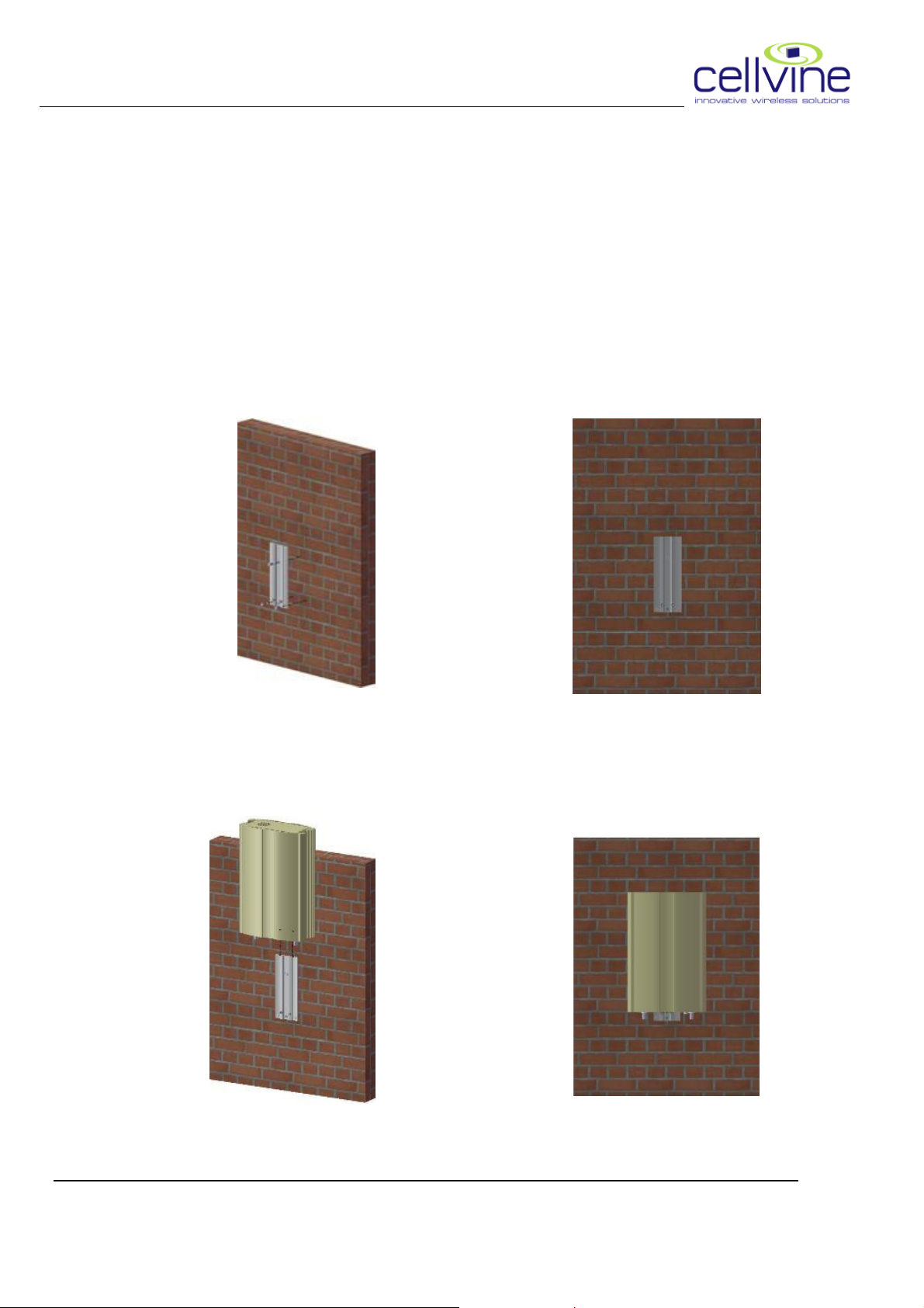
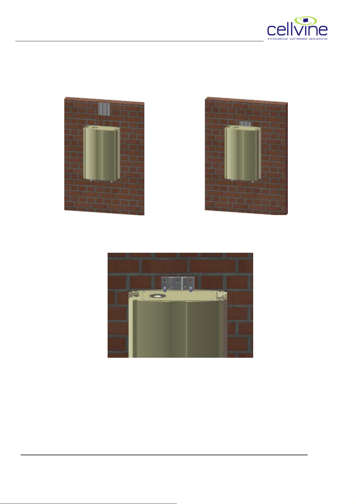
o Use the hardware bracket supplied to mount the Repeater to a solid
location as show in Figures 3-1to 3-8.
o Install the Lower (Long) bracket on the wall in vertical position using
three fixing screws ÷ M6 (or 1/4 ") socket pan screw, M6 plain washer,
M6 spring washer.(Figure 3-1,3-2)
Figure 3-1 Figure 3-2
o Slide the repeater on the lower bracket from top (Figure 3-3, 3-4).
Figure 3-3 Figure 3-4
BDA-AWS21-26-4UT-AB-JXX Rev 1.06 2009-05
10
Page 22
CELLVINE LTD. BDA-AWS21-26-4UT-AB-JXX
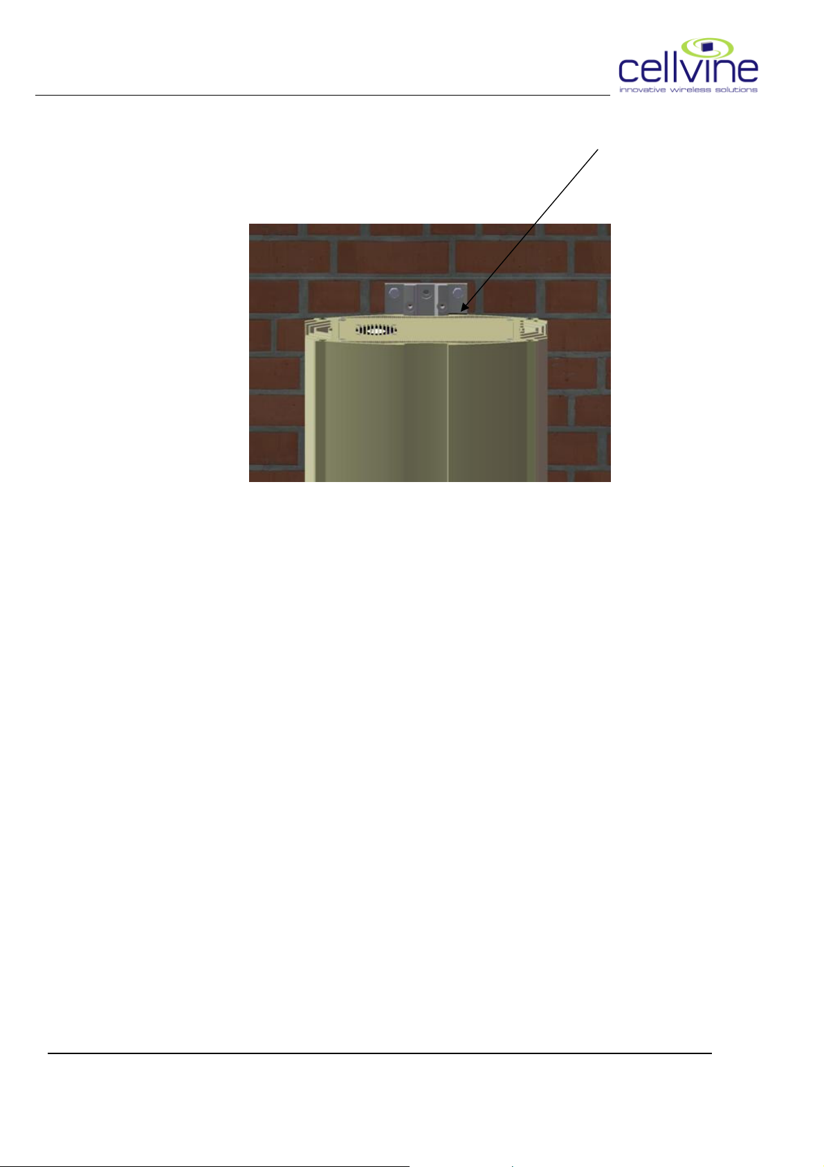
o Slide the Upper bracket (Short) and mark the drilling points for the
upper bracket (use the black marker on the bracket Figure 3-5,3-6,3-7)
Figure 3-5 Figure 3-6
Figure 3-7
o Take out the Upper bracket and the repeater and drill the needed holes.
BDA-AWS21-26-4UT-AB-JXX Rev 1.06 2009-05
11
Page 23
CELLVINE LTD. BDA-AWS21-26-4UT-AB-JXX
o Re slide the repeater and the upper bracket (till the black marker),
Connect the two upper screws and fasten the bracket to the wall (Figure
3-7,3-8).
Figure 3-8
o Make sure that the antenna cable connectors and the Repeater
connectors are clean and dry.
o Connect the Donor antenna cable to the "DONOR" RF connector.
o The connection should be snug and tight.
o Connect the "service" (coverage) antenna cable to the service RF
connector. The connection should be snug and tight.
o Ensure that the antenna cables have not been crimped, kinked, or
otherwise damaged in the process.
BDA-AWS21-26-4UT-AB-JXX Rev 1.06 2009-05
12
Page 24
CELLVINE LTD. BDA-AWS21-26-4UT-AB-JXX
3.5.2 Power supply Installation
3.5.2.1 Bracket
3.5.2.1 Bracket MMMMounting
3.5.2.1 Bracket 3.5.2.1 Bracket
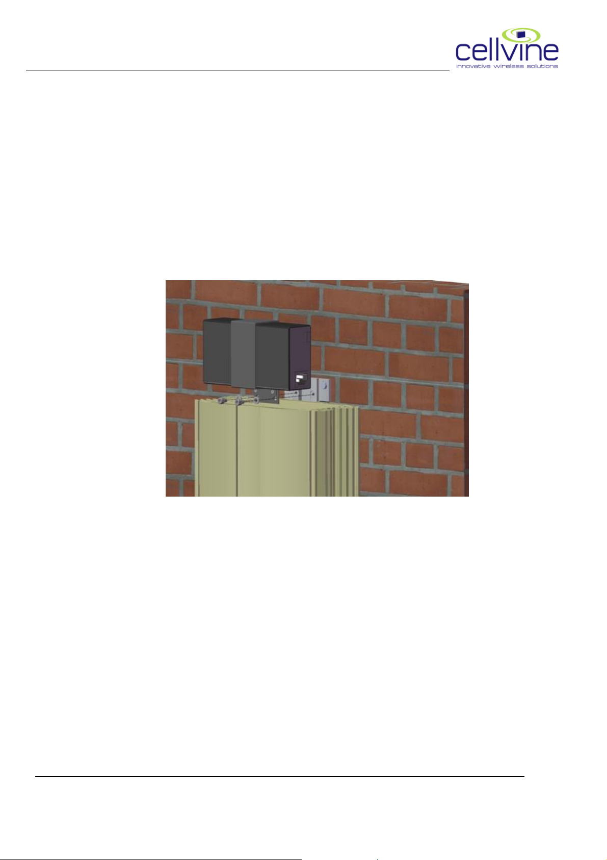
• Take out the 2 Allen screws mount the power supply on the bracket
• re insert the screw and the spring lock washers, fasten the screws to
the bracket (see figure 3-9)
ounting
ountingounting
Figure 3-9
• Connect the DC cable to the repeater
• Connect the AC cable to the Power supply and than to the AC
outlet.
3.5.2.2 Wall Mounting
3.5.2.2 Wall Mounting
3.5.2.2 Wall Mounting3.5.2.2 Wall Mounting
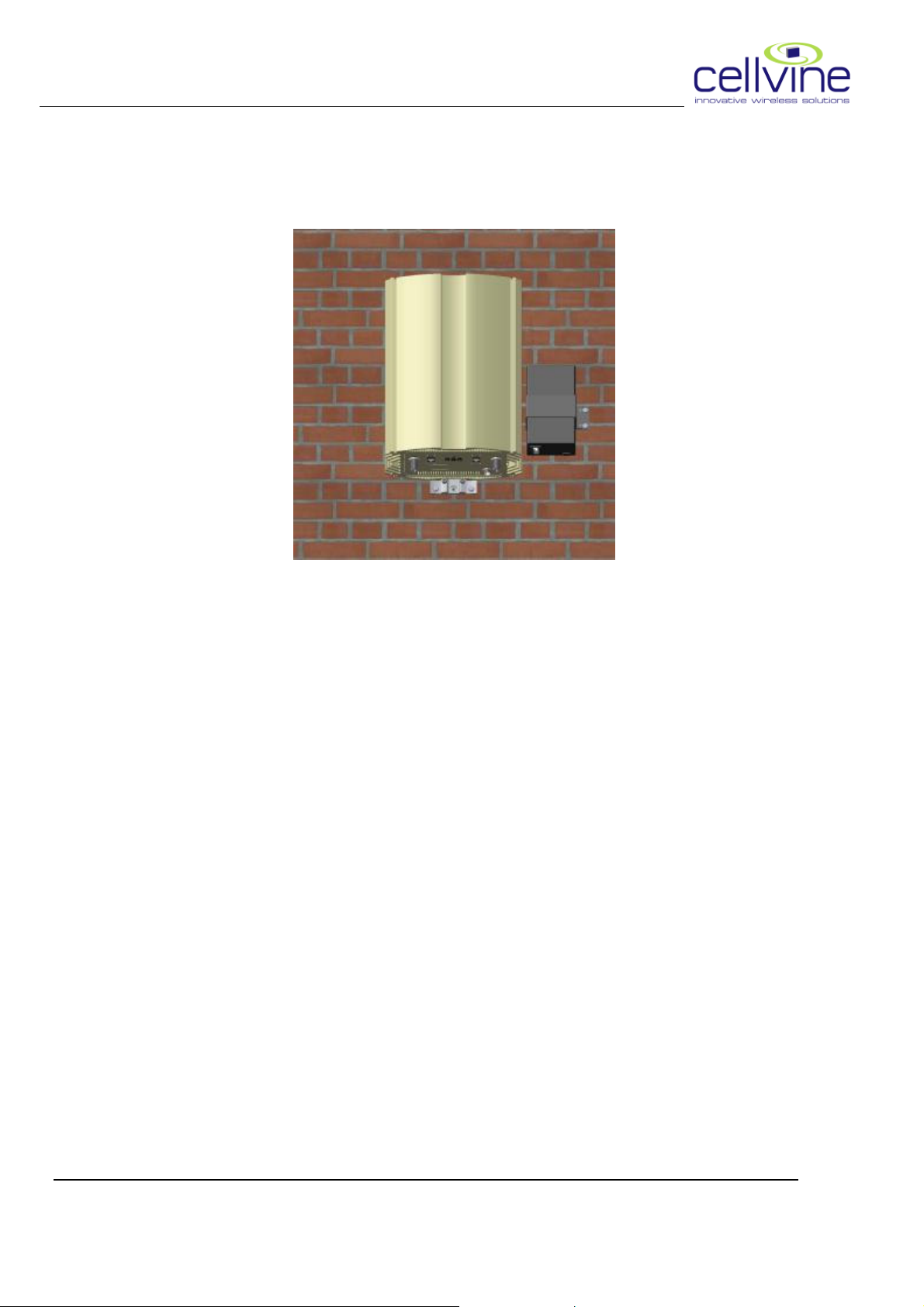
Take the power supply kit (Power supply +attached bracket) place it on the
wall and mark the holes for drilling.
Drill the 2 holes and than fasten the kit to the wall with 2 screws. (Figure 3-
10).
BDA-AWS21-26-4UT-AB-JXX Rev 1.06 2009-05
13
Page 25
CELLVINE LTD. BDA-AWS21-26-4UT-AB-JXX
Figure 3-10
• Connect the DC cable to the repeater
• Connect the AC cable to the Power supply and than to the AC
outlet.
NOTE: Always connect RF connectors to Repeater before applying electric
power!
BDA-AWS21-26-4UT-AB-JXX Rev 1.06 2009-05
14
Page 26
CELLVINE LTD. BDA-AWS21-26-4UT-AB-JXX
Ca
ble
3.6 REPEATER CABLE CONNECTION
DONOR antenna
COM/PC
Service antenna
SNMP/LAN
Cable
Figure 3-1: Cable Connections
BDA-AWS21-26-4UT-AB-JXX Rev 1.06 2009-05
15
Page 27
CELLVINE LTD. BDA-AWS21-26-4UT-AB-JXX
3.7 SYSTEM INDICATIONS
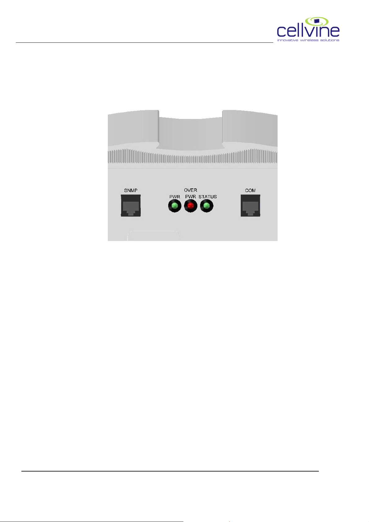
There are three indication LED's on the front panel:
Power, Over Power, Status.
Figure 3-2: Repeater Indications LED's
o PWR: On when the repeater is ON,
o OVER PWR:
Off in normal operation,
On when signal is high (27dBm) and Gain is at minimum value.
Blinking when signal is high (above 27dBm) and the system is shut down
for a period of approximately 1 minute.
o STATUS:
On in normal operation and good DL power
Blinking when DL power is low
BDA-AWS21-26-4UT-AB-JXX Rev 1.06 2009-05
16
Page 28

CELLVINE LTD. BDA-AWS21-26-4UT-AB-JXX
3.8 TUNING DONOR ANTENNA
Locate a potential site for installing the Donor Antenna with an accessible
and comfortable working space. If possible locate a place with a line of sight
to the Donor BTS.
Deploy a coax cable between the Donor antenna and the Repeater location
and connect to the DONOR connector.
In order to achieve the best signal reception quality at the donor antenna,
rotate the antenna gently sideways and measure signal strength by an
approved test set.
3.9 ANTENNA ISOLATION
To assure proper Repeater operation, the isolation between the indoor
(Service) and Donor antennas should be higher than the Repeater's
maximal gain (15dB difference is recommended). This parameter can be
measured by injecting a pilot signal at the indoor antenna's (DAS) connector
and measuring the received signal at the DONOR antenna connector. The
isolation measured should be at least 15dB higher then the MAX GAIN of
the repeater. It is recommended to perform the test using a sweep signal
generator to cover the whole band. It is also recommended, to perform the
test in the opposite direction. (Injecting to the donor antenna and
measuring at the Service antenna's connector).
BDA-AWS21-26-4UT-AB-JXX Rev 1.06 2009-05
17
Page 29
CELLVINE LTD. BDA-AWS21-26-4UT-AB-JXX
4 Repeater Monitoring and Control
This type of repeater can be accessed in two ways for Monitoring and Control:
• Via Ethernet cable in local, web connection or by
• Internet connection via cellular modem
4.1 PREPARING THE REPEATER FOR LOCAL
CONNECTION
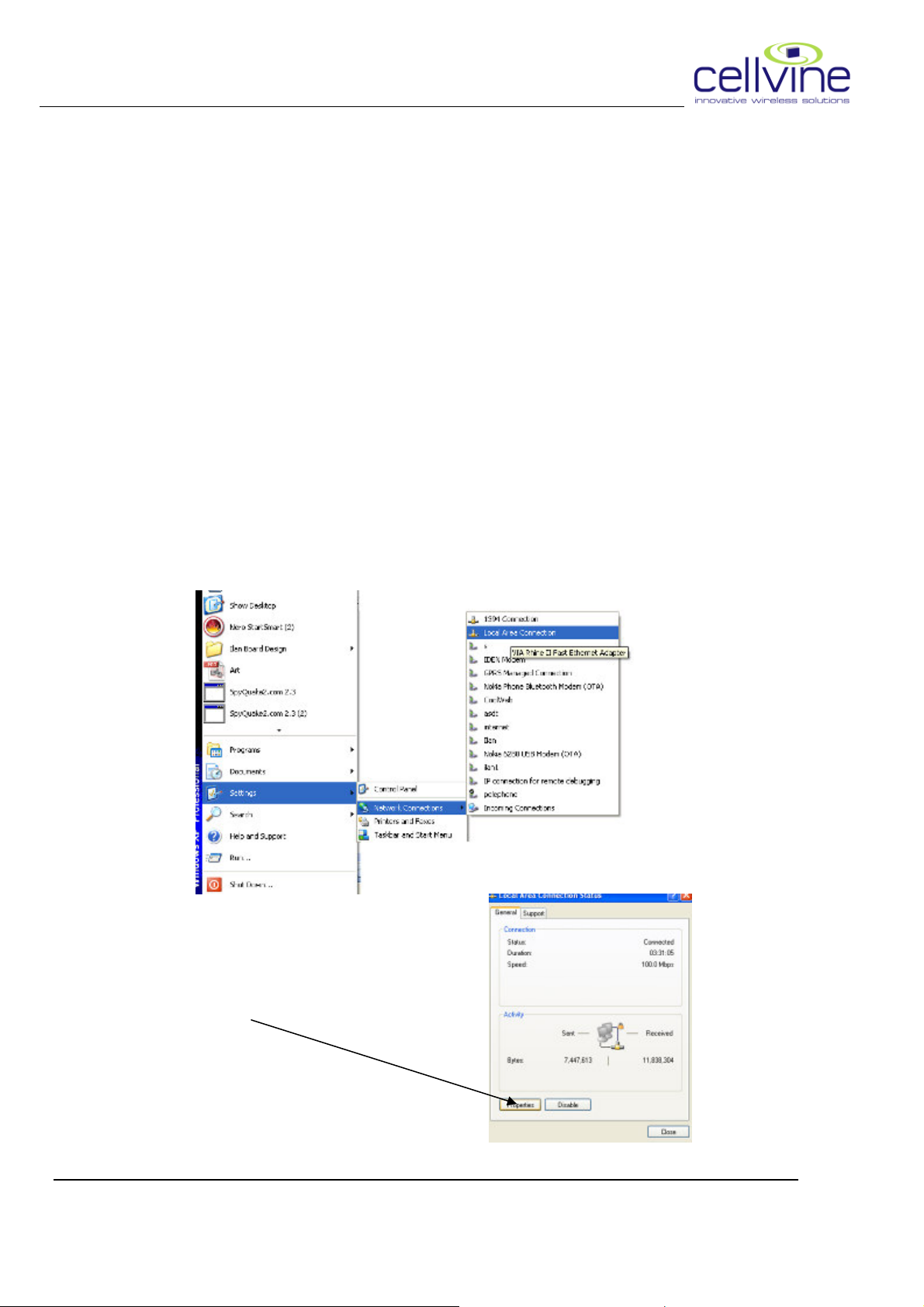
4.1.1 Define PC internet settings:
Go to StartSettingsNetwork ConnectionsLocal Area Connection
Select "Properties"
BDA-AWS21-26-4UT-AB-JXX Rev 1.06 2009-05
18
Page 30
CELLVINE LTD. BDA-AWS21-26-4UT-AB-JXX
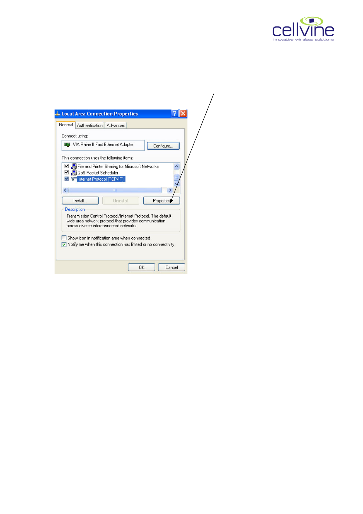
Select "Internet Protocol (TCP/IP), click Properties
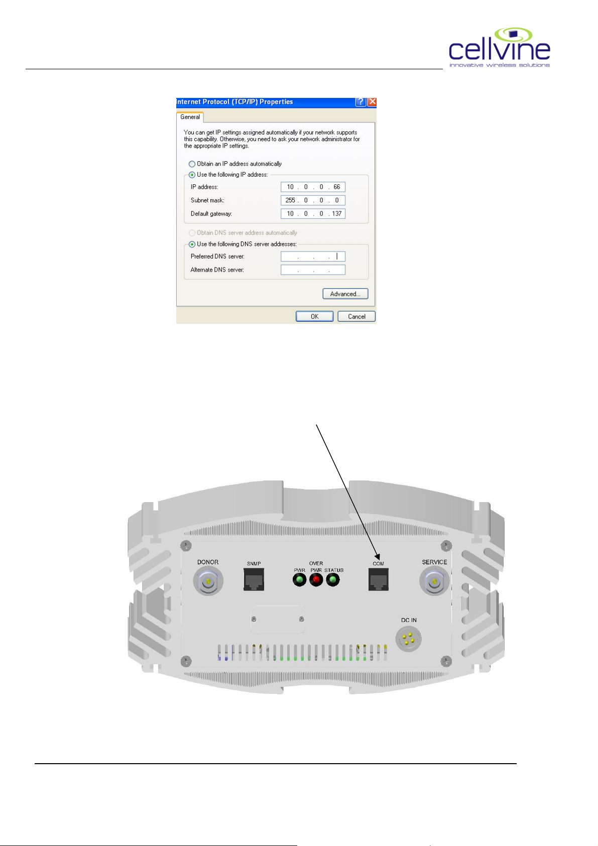
4.1.2 TCP\IP Setting
Define TCP/IP properties as following, then click "OK:
BDA-AWS21-26-4UT-AB-JXX Rev 1.06 2009-05
19
Page 31
CELLVINE LTD. BDA-AWS21-26-4UT-AB-JXX
4.1.3 Ethernet cable connection:
Connect the crossed Ethernet cable (supplied by Cellvine) from the
PC\Laptop to the RJ45 jack on the repeater
BDA-AWS21-26-4UT-AB-JXX Rev 1.06 2009-05
20
Page 32
CELLVINE LTD. BDA-AWS21-26-4UT-AB-JXX
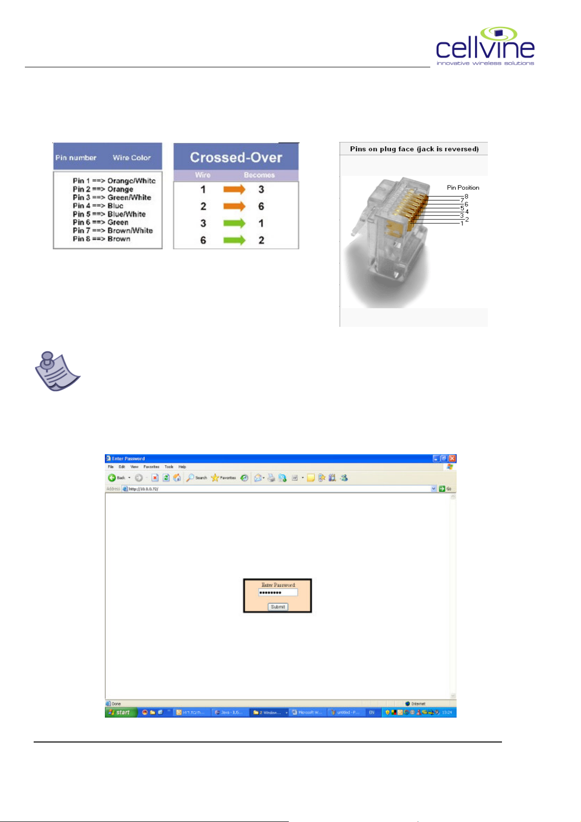
4.1.4 Standard crossed Ethernet cable description
1.
4.1.5 Connection to the repeater Using internet browser:
It is recommended that before connecting to the repeater ,
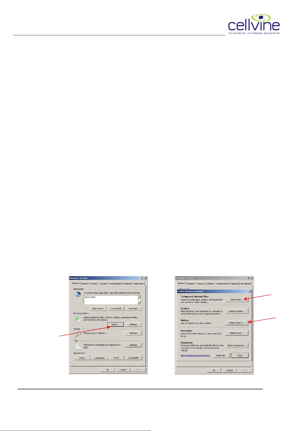
delete all history and temporary files from the Internet Browser.
Go to IP address: 10.0.0.72. (Wait for 2 min after repeater turned on)
Login screen appears:
BDA-AWS21-26-4UT-AB-JXX Rev 1.06 2009-05
21
Page 33
CELLVINE LTD. BDA-AWS21-26-4UT-AB-JXX
• Enter password: Cellvine (all small letters)
• Click "submit"
• The main screen of the repeater will appear.
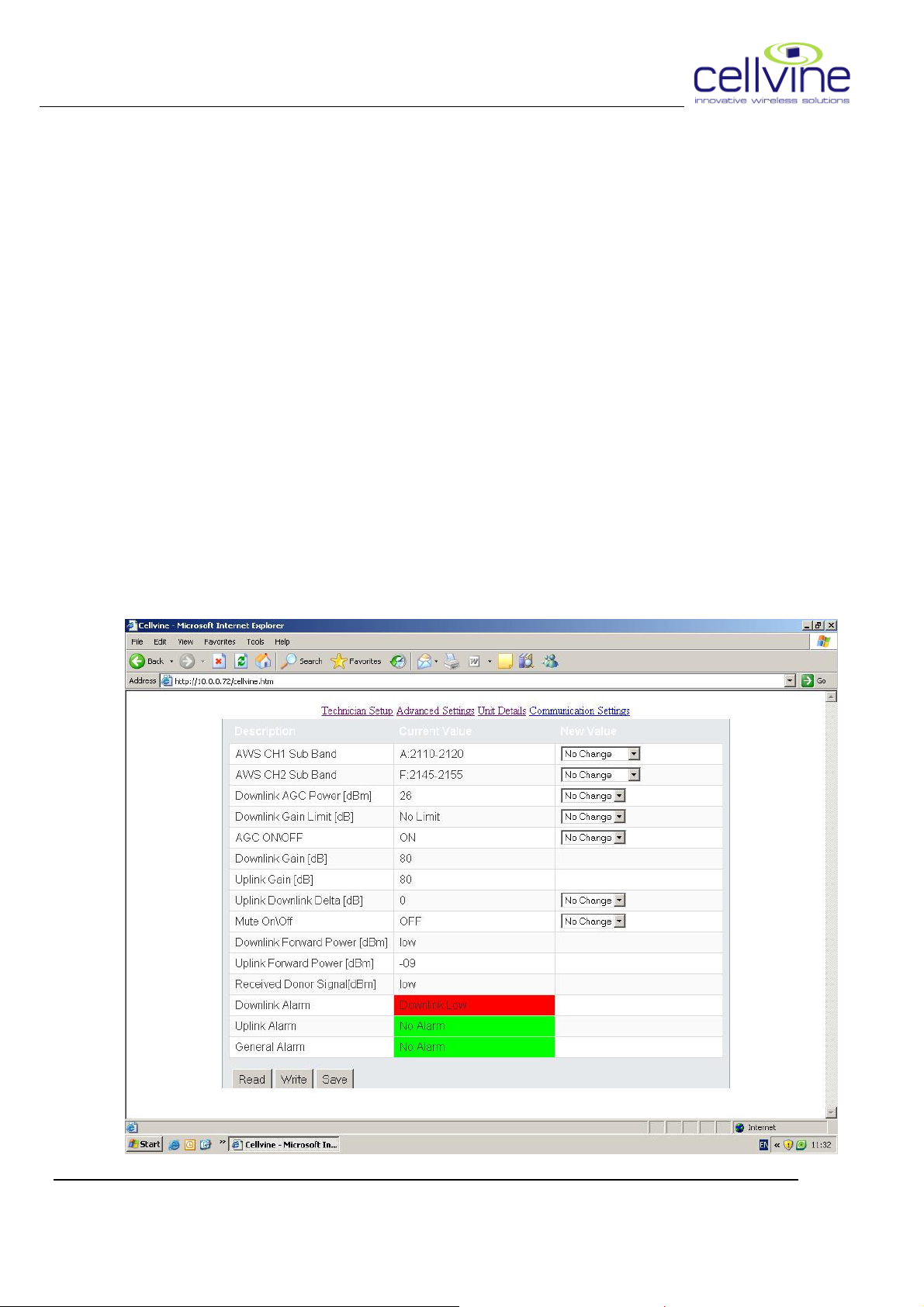
4.2 REPEATER MONITORING AND CONTROL
The main screen is "Technician Setup". The user can set & read all the
important parameters of the repeater following a friendly GUI process.
BDA-AWS21-26-4UT-AB-JXX Rev 1.06 2009-05
22
Page 34

CELLVINE LTD. BDA-AWS21-26-4UT-AB-JXX
4.2.1 Reading parameters and readouts
By pressing "read" the user will get readings of all repeater parameters
and readouts.
Parameters:
AWS CH1 Sub Band - Channel 1 sub band definition from the dropdown list.
AWS CH2 Sub Band - Channel 2 sub band definition from the dropdown list.
Downlink AGC Power [dBm] - The target power that the repeater will try to go
to, will use max gain if needed unless limited by Max Gain
Limit.(effective on AGC ON mode).
Downlink Gain limit [dBm] –The Gain limit (effective on AGC ON mode)
AGC ON/OFF – Turning on or off the AGC mechanism. When AGC is ON the
repeater will try to set the output power to the value set at the "
Downlink AGC Power [dBm]" with the limit of the gain as set on
the " Maximum gain Limit [dBm]".
When AGC is OFF the repeater will amplify according to the
values set on "Downlink Gain [dBm]" and Uplink gain [dBm]
respectively.
Downlink Gain [dB] – The gain value that the repeater will amplify on the
Downlink path (effective on AGC OFF mode)
Uplink Gain [dB] – The gain value that the repeater will amplify on the Uplink path
(effective on AGC OFF mode)
Uplink Downlink Delta [dB] - The difference in dB between the Downlink gain
and the uplink gain. (-) sign mean that the uplink gain is lower
than the uplink gain by X dB. Recommended value is -1 to -3.
Mute ON/OFF – Mute is the function of turning off the power amplifiers of both
Uplink and Downlink paths. Turning it on will shutdown the
amplifiers.
BDA-AWS21-26-4UT-AB-JXX Rev 1.06 2009-05
23
Page 35

CELLVINE LTD. BDA-AWS21-26-4UT-AB-JXX
READOUTS:
Downlink Gain [dB] - When in AGC ON mode used as the reading of the current
Downlink gain.
Uplink Gain [dB] - When in AGC ON mode used as the reading of the current
Uplink gain.
Downlink Forward Power [dBm] – The power measured by the repeater at the
service port. (Values between 9 to 27,below 9 will display
"LOW")
Uplink Forward Power [dBm] - The power measured by the repeater at the
Donor port. (Reading is usually "LOW" since output to the
donor is with low power)
Uplink RSSI [dBm] - The measurement of the signal coming to the service port.
(Equal to " [Uplink Forward Power [dBm]] – [Uplink Gain [dB]],
Downlink Alarm - Display the alarms exist on the Downlink (If there is no alarms
will display "No Alarms").
Uplink Alarm - Display the alarms exist on the Uplink (If there is no alarms
will display "No Alarms ").
General Alarm - Display general alarms (If there is no alarms will display "No
Alarms ").
BDA-AWS21-26-4UT-AB-JXX Rev 1.06 2009-05
24
Page 36
CELLVINE LTD. BDA-AWS21-26-4UT-AB-JXX
4.2.2 Writing parameter
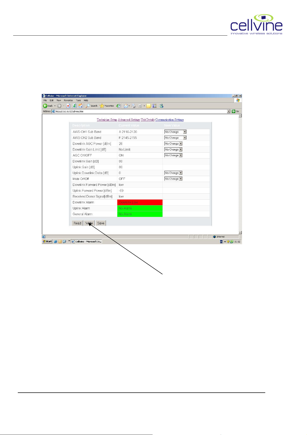
The user can select new value for a parameter (in this example "AWS
CH1 Sub Band") using the "New Value" drop down window and clicking
the required value.
In order to update the value press "Write"
When selecting a new value all other values are blocked, ( the selection
boxes become pale) unless "write" button is pressed, or "No Change" is
selected.
All the parameters that have "New Value" box can be updated in the same
way.
BDA-AWS21-26-4UT-AB-JXX Rev 1.06 2009-05
25
Page 37
CELLVINE LTD. BDA-AWS21-26-4UT-AB-JXX
4.2.3 Saving parameter
In order to keep the parameters after repeater power shutdown and
recover them, the user needs to click "Save", this will save the current
values to repeater's non volatile memory.
4.2.4 Advanced settings
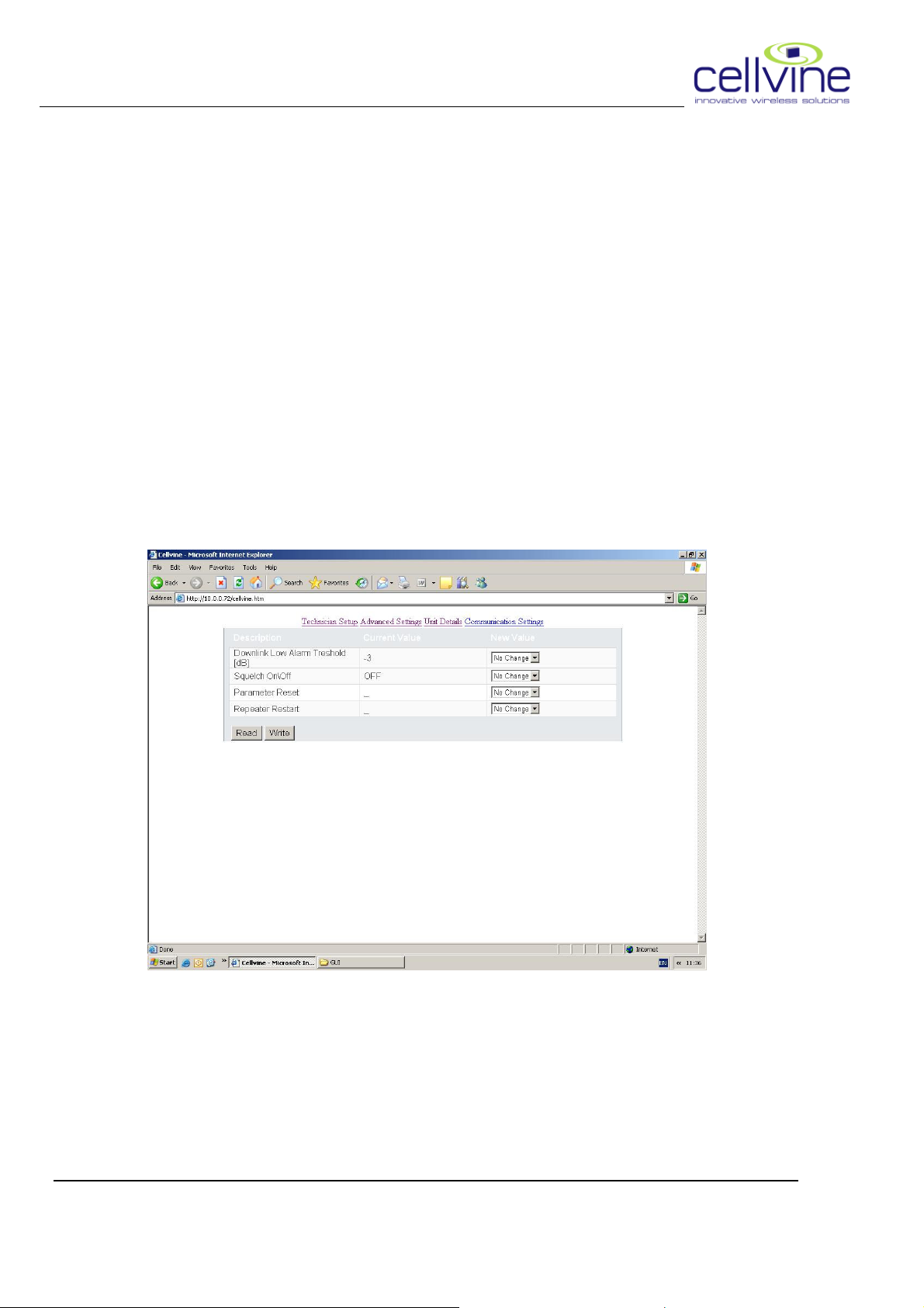
In this screen the user sets the general setting of the repeater
Downlink Low Alarm Threshold – this parameter sets the allowed
downlink power delta from AGC power before generating an alarm.
BDA-AWS21-26-4UT-AB-JXX Rev 1.06 2009-05
26
Page 38

CELLVINE LTD. BDA-AWS21-26-4UT-AB-JXX
Squelch On/Off – Enable/disable the squelch function
Parameter Reset - Return the repeater parameters to the last known
saved.
Repeater Restart – Resume repeater operation after shut down.
(Pressing "save" in "Technician Setup" screen also saves this screen
parameters)
BDA-AWS21-26-4UT-AB-JXX Rev 1.06 2009-05
27
Page 39
CELLVINE LTD. BDA-AWS21-26-4UT-AB-JXX
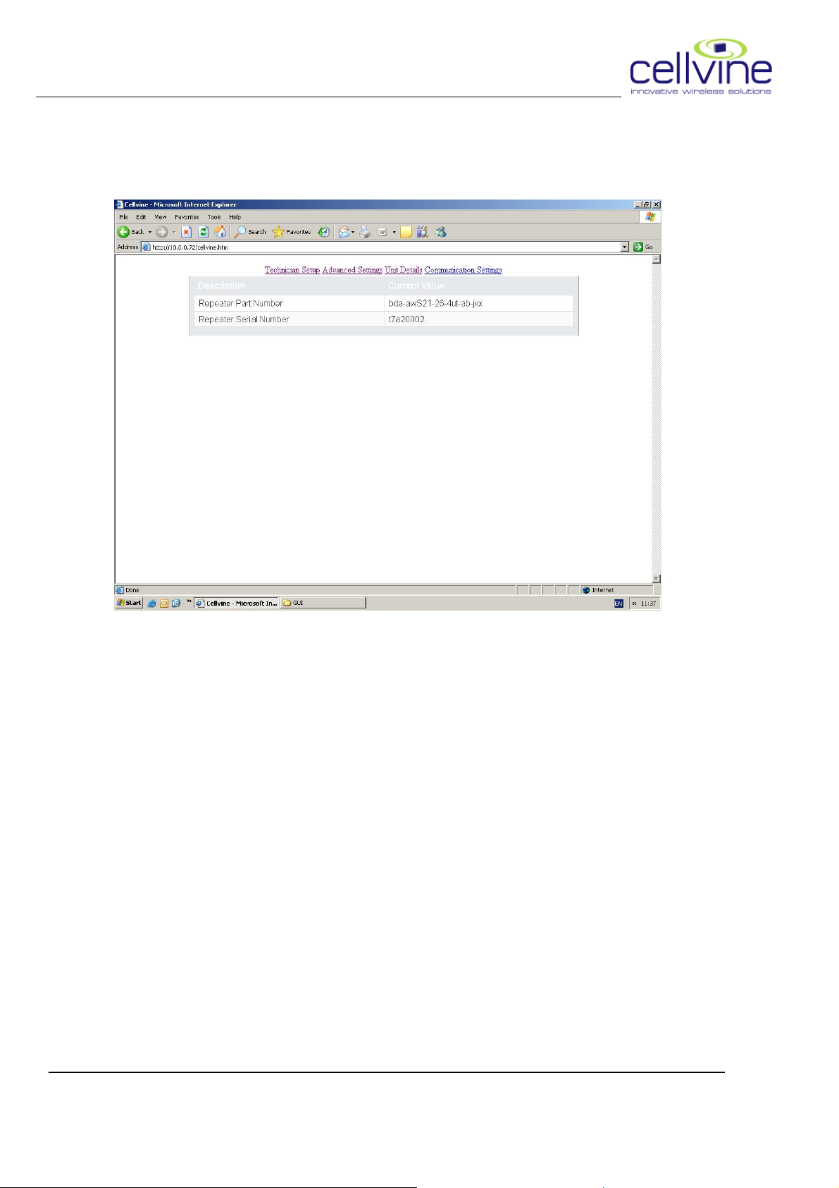
4.2.5 Unit Details
This screen shows the unit part number & serial number
BDA-AWS21-26-4UT-AB-JXX Rev 1.06 2009-05
28
Page 40
CELLVINE LTD. BDA-AWS21-26-4UT-AB-JXX
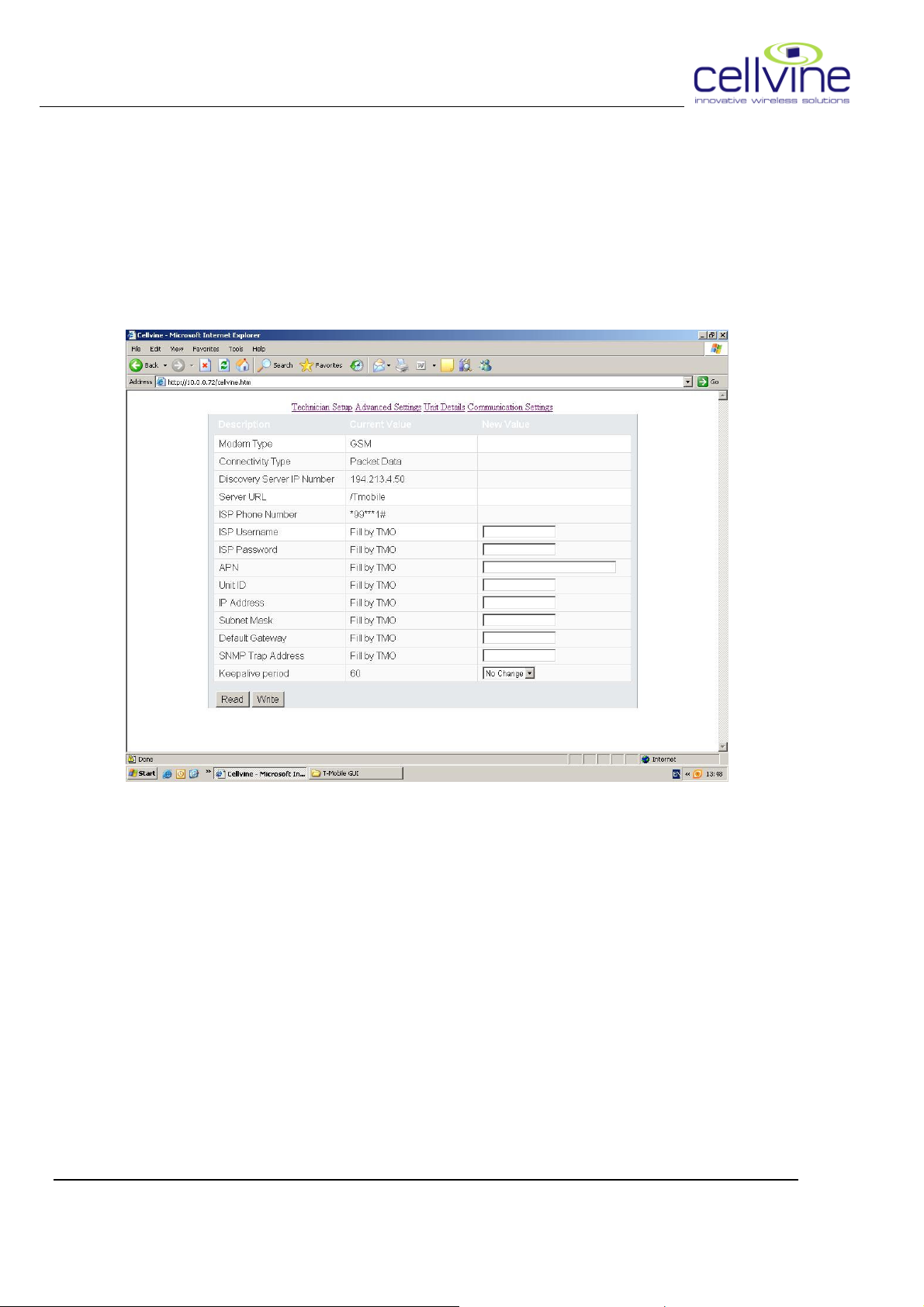
4.2.6 Communication setting
Use this tab for wireless internet connection via modem
This screen shows the IP communication definitions
The parameters can be set by the technician:
Modem type:
Connectivity type:
Discovery Server IP Number: this parameter is supplied as defined by the
operator; if the server IP has changed the technician can set it
Server URL: Default value is Cellvine's management server
ISP Phone Number:
ISP Username: the cellular internet provider username (operator defined)
BDA-AWS21-26-4UT-AB-JXX Rev 1.06 2009-05
29
Page 41

CELLVINE LTD. BDA-AWS21-26-4UT-AB-JXX
ISP Password: the cellular internet provider password (operator defined)
All others fields will be explained on the MOP doc and other T-Mobile
documents.
All screen parameters are saved automatically upon pressing "Write"
BDA-AWS21-26-4UT-AB-JXX Rev 1.06 2009-05
30
Page 42
CELLVINE LTD. BDA-AWS21-26-4UT-AB-JXX
4.3 PREPARING THE REPEATER FOR REMOTE
CONNECTION VIA INTRANET:
4.3.1 Initiating the modem:
• Make sure that the repeater is switched OFF
• Make sure that a modem is installed in the repeater
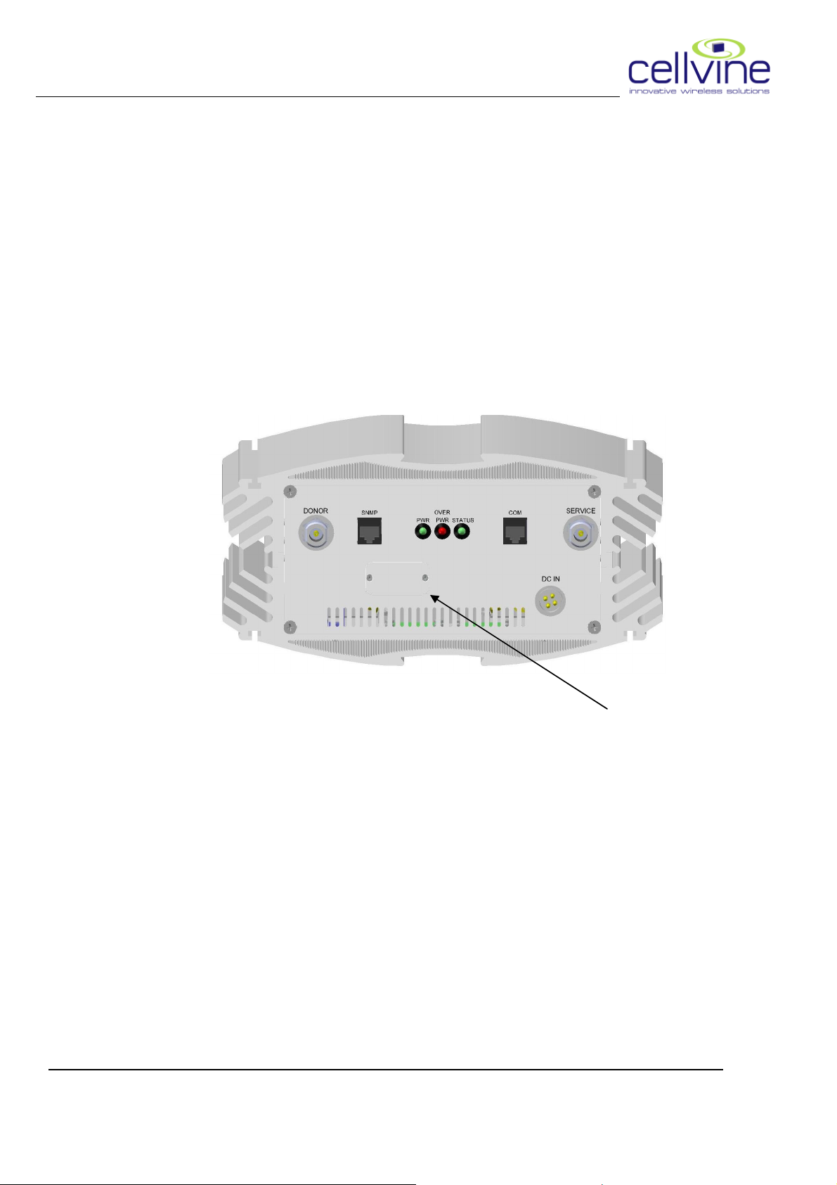
Insert SIM card into the modem through the SIM card slot:
- Open 2 screws and remove SIM card cover.
- Press the yellow button using a sharp tool (like pen tip) and
pull out the SIM card plastic tray.
- Place the SIM card in the tray and insert the tray back into
the slot.
- Place the cover and fasten it with the 2 screws.
• Turn the repeater ON.
BDA-AWS21-26-4UT-AB-JXX Rev 1.06 2009-05
31
Page 43
CELLVINE LTD. BDA-AWS21-26-4UT-AB-JXX
5 TROUBLESHOOTING
5.1 Connection Failure
Trying to locally connect to the repeater via the internet browser fail
Possible reason:
1. Adress typed is not correct.
2. TCP/IP definitions are not correct.
3. Communication port on the repeater is not ready yet.
4. The Ethernet cable is not the original (Crossed).
Solution:
Check cable and reconnect it, verify configuration according to chapter 4.1,
clean all temporary internet files and history on your internet browser, wait 2
min for repeater "warm up" and try to connect.
5.2 GUI Parameters not update correctly
Parameters coming from the repeater not updated as they should.
Possible reason:
1. Internet browser cache is full
Solution:
Delete temporary internet files and history on your internet browser
BDA-AWS21-26-4UT-AB-JXX Rev 1.06 2009-05
32
Page 44

CELLVINE LTD. BDA-AWS21-26-4UT-AB-JXX
5.3 Modem can't connect to the NMS server
Trying to connect to the server (Via the modem) fail.
Possible reason:
1. SIM is not inserted.
2. SIM is not configured properly (APN, Data services, etc'. e.g.
3. Repeater APN definition is not configured properly.
4. RF Receive level is too low.
5. Network definitions for the SIM are not correct.
Solution:
Verify SIM card inserted correctly (chapter 4.3.1).
Verify all definitions are set to the correct value (at the switch/HLR/SIM card)
Check the reception of the GSM/GPRS signal coming from the donor site.
5.4 Call Fails.
Trying to make calls through the repeater fails although signal strength from the
donor is OK and DAS network working properly. (Good indoor coverage).
Possible reason:
1. Cell Range parameter on the donor site not configured to include
repeater delay.
2. Other network parameters related to delay are not set properly.
Solution:
Verify that the parameters on the network take into account the delay of the
repeater + the extended coverage range of the repeater.
BDA-AWS21-26-4UT-AB-JXX Rev 1.06 2009-05
33
 Loading...