

Celestron CGE925, CGE800, CGE1400, CGE1100 User Manual
IINNSSTTRRUUCCTTIIOONN MMAANNUUAAL
CCGGEE880000 ●● CCGGEE992255
L
●● CCGGEE11110000
●●
CCGGEE11440000

INTRODUCTION..................................................................................................................................................................................4
g ..............................................................................................................................................................................................4
WWaarrnniinng
ASSEMBLY ...........................................................................................................................................................................................6
Setting up the Tripod...........................................................................................................................................................................6
Attaching the Center Leg Brace ..........................................................................................................................................................7
Attaching the Electronics Pier.............................................................................................................................................................7
Attaching the Equatorial Mount..........................................................................................................................................................8
Installing the Counterweight Bar ........................................................................................................................................................8
Installing the Counterweight...............................................................................................................................................................8
Attaching the Optical Tube to the Mount............................................................................................................................................9
Attaching the Visual Back...................................................................................................................................................................9
Installing the Star Diagonal...............................................................................................................................................................10
Installing the Eyepiece......................................................................................................................................................................10
Installing the Finderscope.................................................................................................................................................................11
Moving the Telescope Manually.......................................................................................................................................................12
Adjusting the Mount.........................................................................................................................................................................12
Balancing The Mount in R.A. ...........................................................................................................................................................13
Balancing The Mount in DEC...........................................................................................................................................................13
Attaching the Motor Cables ..............................................................................................................................................................14
Powering the Telescope ....................................................................................................................................................................14
Transporting the CGE .......................................................................................................................................................................14
HAND CONTROL...............................................................................................................................................................................16
Named Stars ......................................................................................................................................................................................17
Hand Control Operation ....................................................................................................................................................................17
Alignment Procedures.......................................................................................................................................................................18
Startup Procedure..............................................................................................................................................................................18
Auto Two-Star Align ........................................................................................................................................................................19
Auto One-Star Align .........................................................................................................................................................................19
Quick-Align......................................................................................................................................................................................20
Last Alignment .................................................................................................................................................................................20
CGE Re-Alignment...........................................................................................................................................................................20
Object Catalog ..................................................................................................................................................................................21
Selecting an Object............................................................................................................................................................................21
Slewing to an Object .........................................................................................................................................................................21
Finding Planets..................................................................................................................................................................................21
Tour Mode.........................................................................................................................................................................................22
Constellation Tour.............................................................................................................................................................................22
Direction Buttons ..............................................................................................................................................................................22
Rate Button........................................................................................................................................................................................22
Setup Procedures...............................................................................................................................................................................23
Tracking Mode........................................................................................................................................................................23
Tracking Rate..........................................................................................................................................................................23
Date/Time ...............................................................................................................................................................................23
User Defined Objects ..............................................................................................................................................................24
Get RA/DEC...........................................................................................................................................................................24
Goto R.A/Dec..........................................................................................................................................................................24
Identify....................................................................................................................................................................................24
Precise GoTo.....................................................................................................................................................................................25
Scope Setup Features.........................................................................................................................................................................25
Steup Time-Site.......................................................................................................................................................................25
Anti-backlash..........................................................................................................................................................................25
Filter Limits ............................................................................................................................................................................26
Direction Buttons .................................................................................................................................................................... 26
Goto Approach........................................................................................................................................................................26
Autoguide Rates......................................................................................................................................................................26
Mount Settings........................................................................................................................................................................26
Utility Features..................................................................................................................................................................................27
Calibrate Mount ......................................................................................................................................................................27
Move to Switch.......................................................................................................................................................................27
Home Position.........................................................................................................................................................................27
Polar Align ..............................................................................................................................................................................27
Periodic Error Correction........................................................................................................................................................28
Light Control...........................................................................................................................................................................28
Factory Settings.......................................................................................................................................................................28
Version....................................................................................................................................................................................28
Get Alt-Az...............................................................................................................................................................................28

Goto Alt-Az ............................................................................................................................................................................28
Hibernate.................................................................................................................................................................................28
Turn On/Off RTC....................................................................................................................................................................28
Turn On/Off GPS ....................................................................................................................................................................29
Image Orientation..............................................................................................................................................................................31
Focusing............................................................................................................................................................................................32
Calculating Magnification .................................................................................................................................................................32
Determining Field of View................................................................................................................................................................32
General Observing Hints ...................................................................................................................................................................33
ASTRONOMY BASICS......................................................................................................................................................................34
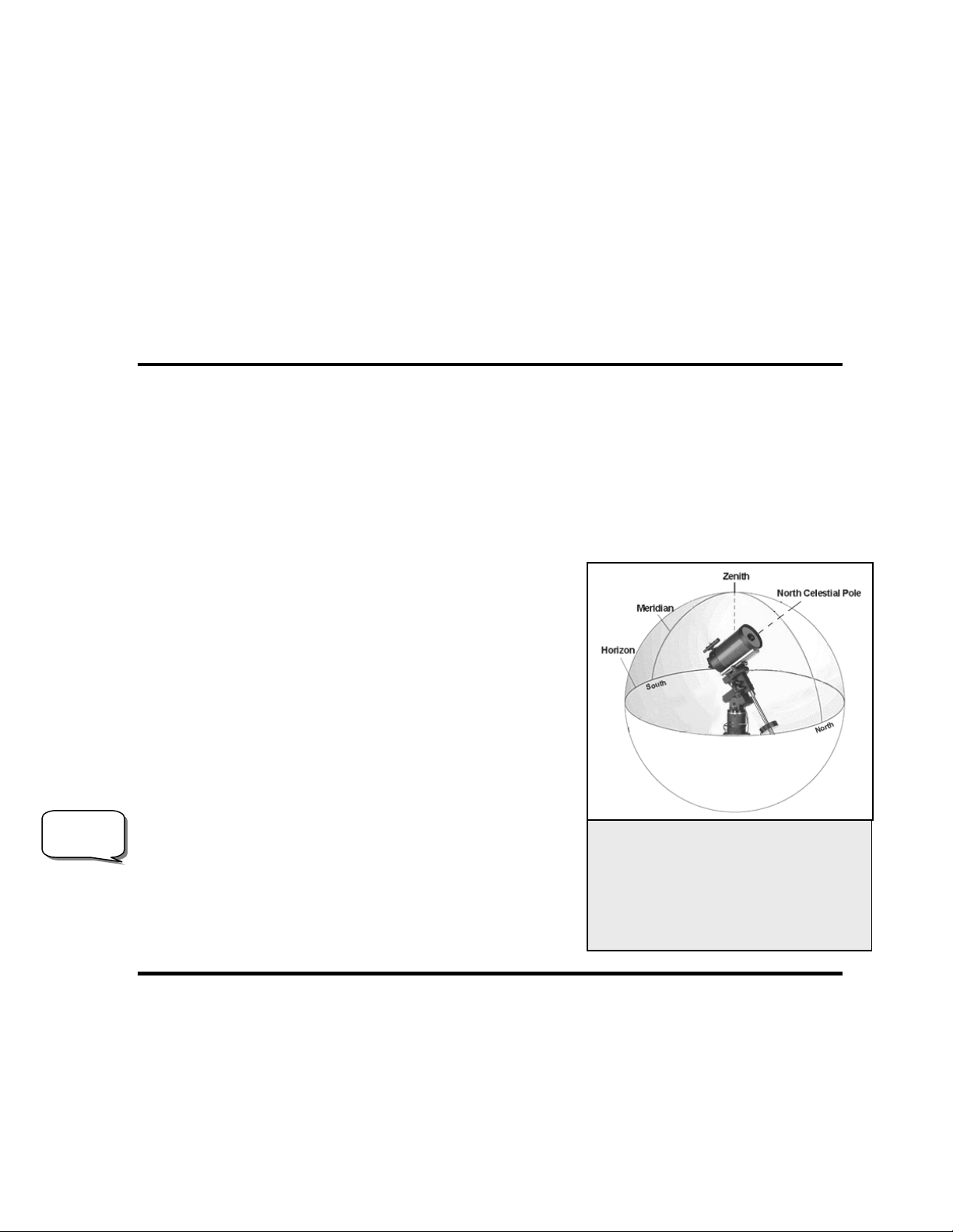
The Celestial Coordinate System.......................................................................................................................................................34
Motion of the Stars............................................................................................................................................................................35
Finding the North Celestial Pole........................................................................................................................................................37
Declination Drift Method of Polar Alignment ...................................................................................................................................38
CELESTIAL OBSERVING................................................................................................................................................................39
Observing the Moon..........................................................................................................................................................................39
Lunar Observing Hints ......................................................................................................................................................................39
Observing the Planets........................................................................................................................................................................39
Observing the Sun .............................................................................................................................................................................40
Solar Observing Hints .......................................................................................................................................................................40
Observing Deep Sky Objects.............................................................................................................................................................40
Seeing Conditions..............................................................................................................................................................................40
Transparency.....................................................................................................................................................................................40
Sky Illumination................................................................................................................................................................................40
Seeing................................................................................................................................................................................................41
ASTROPHOTOGRAPHY .................................................................................................................................................................. 42
Short Exposure Prime Focus Photography ........................................................................................................................................42
Eyepiece Projection...........................................................................................................................................................................43
Long Exposure Prime Focus Photography.........................................................................................................................................44
Periodic Error Correction (PEC)........................................................................................................................................................45
Using Periodic Error Correction ........................................................................................................................................................46
Terrestrial Photography.....................................................................................................................................................................47
Metering............................................................................................................................................................................................47
Reducing Vibration ...........................................................................................................................................................................47
CCD Imaging ....................................................................................................................................................................................47
Fastar F/2 Imaging............................................................................................................................................................................49
F/6.3 with Reducer/Corrector............................................................................................................................................................50
Medium size to small galaxies –........................................................................................................................................................50
Planetary or Lunar-- ..........................................................................................................................................................................50
Auto Guiding.....................................................................................................................................................................................51
TELESCOPE MAINTENANCE ........................................................................................................................................................ 52
Care and Cleaning of the Optics........................................................................................................................................................52
Collimation........................................................................................................................................................................................52
OPTIONAL ACCESSORIES............................................................................................................................................................54
TECHNICAL SPECIFICATIONS....................................................................................................................................................57
APPENDIX A – LONGITUDES AND LATITUDES........................................................................................................................59
APPENDIX B – RS-232 CONNECTION...........................................................................................................................................64
APPENDIX C – TIME ZONE MAP ..................................................................................................................................................66
SKY MAPS...........................................................................................................................................................................................68
3

Congratulations on your purchase of the Celestron CGE telescope! The CGE ushers in the next generation of computer
automated telescopes. The Celestron CGE series continues in this proud tradition combining large aperture
optics with the sophistication and ease of use of our computerized GoTo mount.
If you are new to astronomy, you may wish to start off by using the CGE's built-in Sky Tour feature, which
commands the CGE to find the most interesting objects in the sky and automatically slews to each one. Or if you are
an experienced amateur, you will appreciate the comprehensive database of over 40,000 objects, including customized
lists of all the best deep-sky objects, bright double stars and variable stars. No matter at what level you are starting out,
the CGE will unfold for you and your friends all the wonders of the Universe.
Some of the many standard features of the CGE include:
• Fully enclosed optical encoders for position location.
• Ergonomically designed mount that disassembles into compact and portable pieces
• Database filter limits for creating custom object lists.
• Storage for programmable user defined objects; and
Many other high performance features!
The CGE’s deluxe features combine with Celestron’s legendary Schmidt-Cassegrain optical system to give amateur
astronomers the most sophisticated and easy to use telescopes available on the market today.
Take time to read through this manual before embarking on your journey through the Universe. It may take a few
observing sessions to become familiar with your CGE, so you should keep this manual handy until you have fully
mastered your telescope’s operation. The CGE hand control has built-in instructions to guide you through all the
alignment procedures needed to have the telescope up and running in minutes. Use this manual in conjunction with the
on-screen instructions provided by the hand control. The manual gives detailed information regarding each step as
well as needed reference material and helpful hints guaranteed to make your observing experience as simple and
pleasurable as possible.
Your CGE telescope is designed to give you years of fun and rewarding observations. However, there are a few things
to consider before using your telescope that will ensure your safety and protect your equipment.
WWaarrnniinngg
Y Never look directly at the sun with the naked eye or with a telescope (unless you have
the proper solar filter). Permanent and irreversible eye damage may result.
Y Never use your telescope to project an image of the sun onto any surface. Internal heat build-up can damage the
telescope and any accessories attached to it.
Y Never use an eyepiece solar filter or a Herschel wedge. Internal heat build-up inside the telescope can cause these
devices to crack or break, allowing unfiltered sunlight to pass through to the eye.
Never leave the telescope unsupervised, either when children are present or adults who may not be familiar with the
correct operating procedures of your telescope
.
4
ASSE
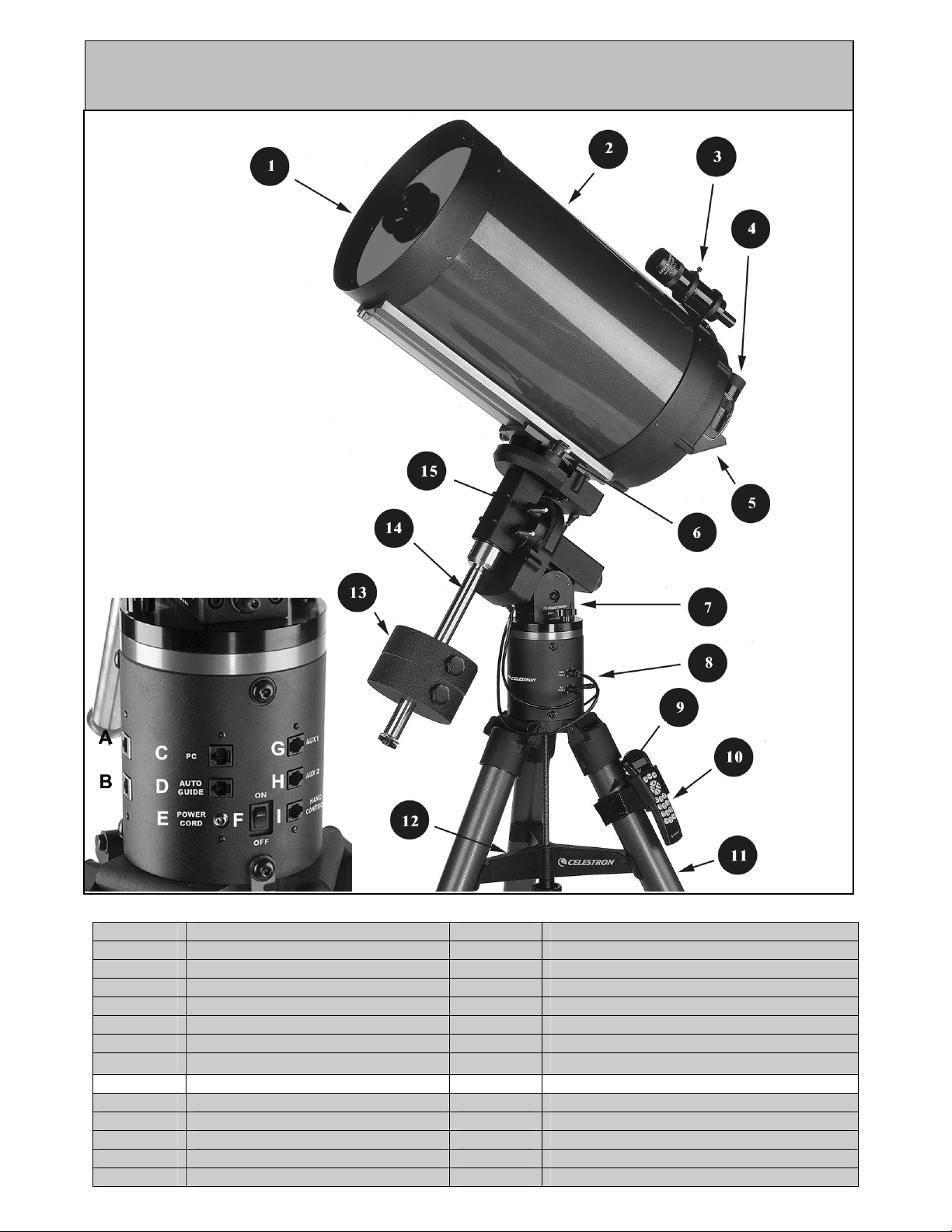
Figure 2.1 - The CGE Telescope
(CGE 1400 Shown)
1 Schmidt Corrector Lens 8 Control Panel (see below)
2 Optical Tube 9 Hand Control Holder / Strap
3 Finderscope 10 Hand Control
4 Eyepiece 11 Tripod
5 Star Diagonal 12 Tripod Center Leg Brace
6 Declination Clutch Lock 13 Counterweights
7 Latitude Adjustment Scale 14 Counterweight Bar
15 R.A. Clutch Lock
CONTROL PANEL E 12v Output Jack
A Dec Motor Port F On/Off Switch
B R.A. Motor Port G Auxiliary Port 1
C PC Interface Port H Auxiliary Port 2
D Auto Guider Port I Hand Control Port
5

This section covers the assembly instructions for your Celestron CGE telescope. The CGE telescope should be set up
indoors the first time so that it is easy to identify the various parts and familiarize yourself with the correct assembly
procedure before attempting it outdoors.
Eyepiece
Diagonal
Finderscope
Power Supply
Counterweight
The Celestron CGE telescopes are shipped in four boxes (the CGE 1400 comes in five boxes). In separate boxes are the
following:
• Optical Tube Assembly and Standard Accessories
• Equatorial Mount, Electronic Pier, Hand Control and Counterweight Bar
• Super HD Tripod
• Counterweight(s)
Remove all the pieces from their respective boxes and place on a flat, clear work area. A large floor space is ideal. When
setting up your Celestron telescope you must start with the tripod and work up from there. These instructions are laid out in
the order each task must be performed.
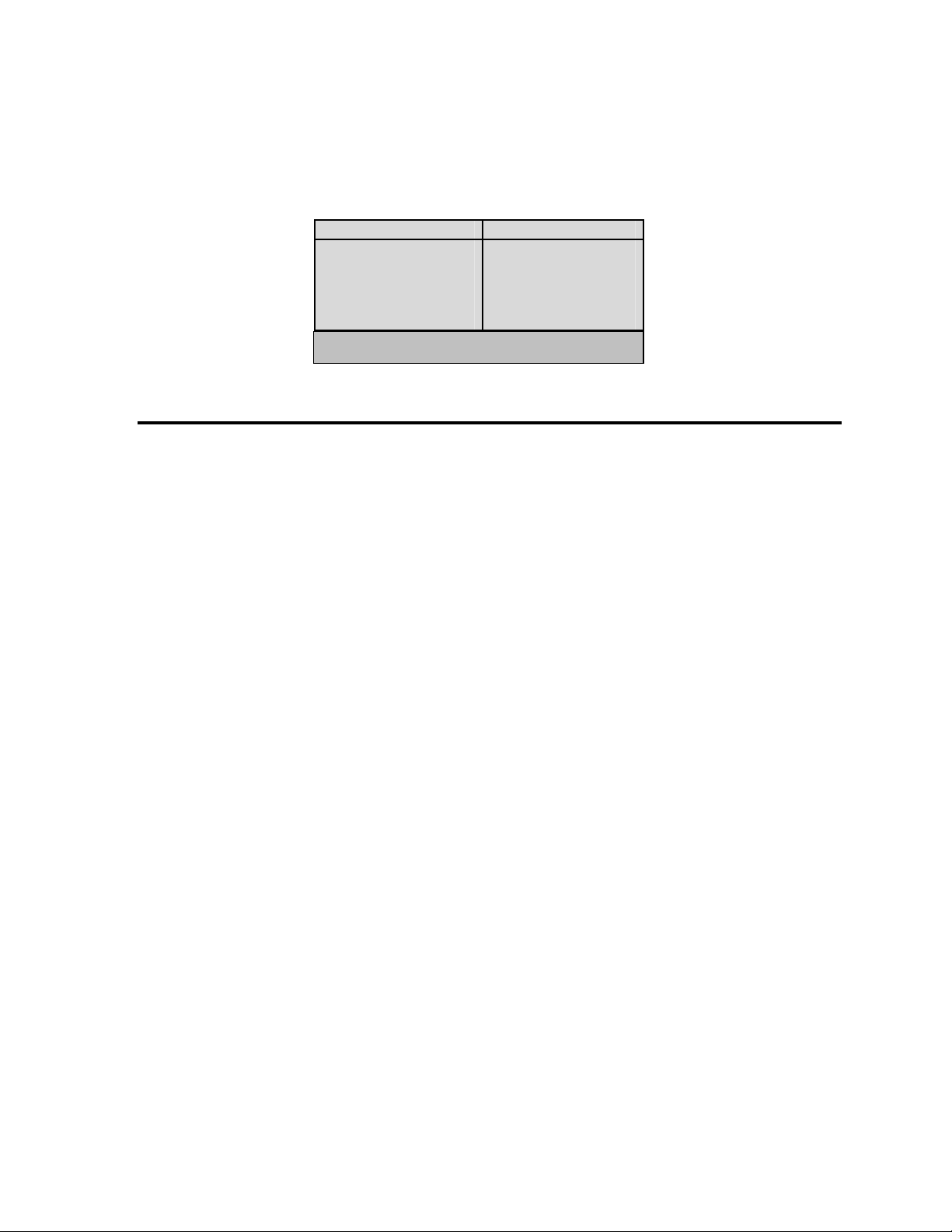
CGE 800 (#11058) CGE 925 (#11059) CGE 1100 (#11061) CGE 1400 (#11063)
25mm Plossl
Eyepiece - 1.25"
Star Diagonal - 1.25" Star Diagonal - 1.25" Star Diagonal - 1.25" Mirror Diagonal –2"
6x30 with Bracket 6x30 with Bracket 9x50 with Bracket 9x50 with Bracket
Car Battery Adapter Car Battery Adapter Car Battery Adapter Car Battery Adapter
One - 11 lb. One - 25 lb. One - 25 lb. Two – 25 lb.
25mm Plossl
Eyepiece - 1.25"
40mm Plossl
Eyepiece - 1.25"
40mm Eyepiece - 2"
Setting up the Tripod
The tripod legs attach to the electronics pier which together form the tripod to which the equatorial mount attaches. The
tripod comes with two leg support brackets; a collapsible one that is already attached to the lower legs and a removable one
that must be attached. To set up the tripod:
1. Stand the tripod vertically on a level surface, with the feet facing down.
2. Grab the lower portion of two of the tripod legs and lift them slightly off the ground so that the tripod is resting on the third
leg.
3. Extend the tripod legs by pulling the tripod legs apart until the collapsible leg bracket is fully extended.
Before the tripod is ready to support the equatorial head and optical tube the center leg support brace must first be installed.
6
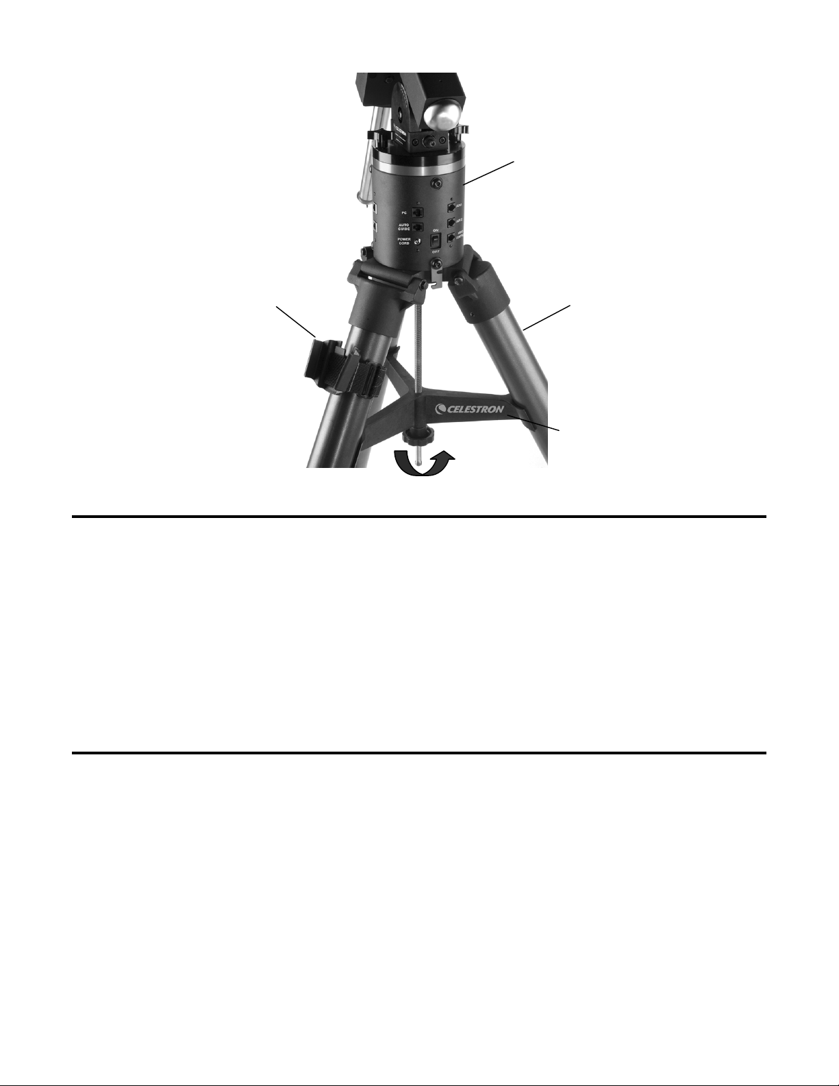
Electronincs
l
Hand Contro
Holder
Figure 2-2
Tripod Leg
Center Leg
Brace
Attaching the Center Leg Brace
For maximum rigidity, the Super HD Tripod has a center leg brace that installs on to the threaded rod below the tripod head.
This brace fits snugly against the tripod legs, increasing stability while reducing vibration and flexure. To attach the center
leg brace:
1. Unscrew the tension knob from the threaded rod beneath the tripod head.
2. Place the center leg brace onto the threaded rod so that the cup on the end of each bracket contours to the curve of
the tripod legs.
3. Rotate the tension knob back on the threaded rod until the brace is very snug against each tripod leg.
Attaching the Electronics Pier
Before the equatorial mount head can be installed, the electronics pier must be attached to the tripod. To attach the pier:
1. Position the central column so that the electronics module is right side up (with the printing readable).
2. Place the lower end of the central column over the tripod head.
3. Rotate the column until the three holes line up with the threaded holes on the side of the tripod head. The electronics
console should be positioned directly between two of the tripod leg hinges to provide easy access to it even when the
counterweight bar and counterweight(s) are attached.
4. Insert the three 3/8-16 button head cap screws provided through the holes in the electronics pier and into the tripod
head.
7
5. Tighten the screws to hold the column securely in place.
w
Attaching the Equatorial Mount
After the tripod is set up, you are ready to attach the equatorial mount. The equatorial mount is the platform to which the
telescope attaches and allows you to move the telescope in right ascension and declination. To attach the equatorial mount to
the tripod:
1. Insert the base of the equatorial mount into the top of the electronics pier.
2. Rotate the equatorial mount on the electronics pier until the holes in the mount line up with those in the pier and the dec
opening (where the counterweight shaft will go) is positioned directly over one of the tripod legs.
3. Insert the three remaining 3/8-16 cap screws and washers provided through the holes in the central pier and into the
equatorial mount.
4. Tighten the screws to hold the equatorial mount in place.
Installing the Counterweight Bar
To properly balance the telescope, the mount comes with a
counterweight bar and at least one counterweight (depending
on model). The counterweight bar is located in the same box
as the Equatorial Mount Head —in a cutout along the bottom
of the shipping box. To install the counterweight bar:
1. Locate the opening in the equatorial mount on the DEC axis
It is opposite the telescope mounting platform.
2. Thread the counterweight bar into the opening until tight.
Once the bar is securely in place you are ready to attach the
counterweight.
Since the fully assembled telescope is quite heavy, position the mount so that the tripod leg with the counterweight bar
over it is pointing towards north before the tube assembly and counterweights are attached. This will make the polar
alignment procedure much easier.
Counterweight
Dec Axis
Bar
Figure 2-3
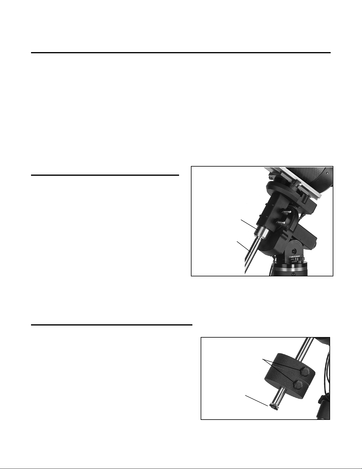
Installing the Counterweight
Depending on which CGE telescope you have, you will receive
either one or two counterweights. To install the counterweight(s):
1. Orient the mount so that the counterweight bar points toward the
ground .
2. Remove the counterweight safety thumbscrew and washer on the
end of the counterweight bar (i.e., opposite the end that attaches to
the mount).
3. Loosen the locking screw on the side of the counterweight.
4. Slide the counterweight onto the shaft.
8
Counterweight
Locking Screw
Safety Scre
and Washer
Figure 2-4
5. Tighten the locking screw on the side of the weight to hold the counterweight in place.
6. Replace the counterweight safety thumbscrew and washer.
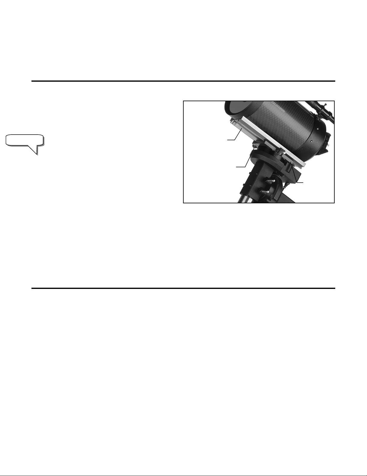
Attaching the Optical Tube to the Mount
The telescope attaches to the mount via a dovetail slide
bar which is mounted along the bottom of the telescope
tube. Before you attach the optical tube, make sure that
the declination and right ascension clutch knobs are
tight. This will ensure that the mount does not
Important!
1 Loosen the locking knobs on the side of the telescope mounting platform. This allows you to slide the dovetail bar on the
telescope onto the mount.
2 Slide the dovetail bar on the telescope tube into the mounting platform of the mount. Slide the telescope so that the back of
the dovetail bar is almost flush with the back of the mounting platform.
3 Tighten the locking knobs on the side of the mounting platform to hold the telescope in place.
Now that the optical tube is securely in place, the visual accessories can now be attached to the telescope.
move suddenly while attaching the telescope. To
mount the telescope tube:
In order for the CGE mount to successfully locate
its declination switches, the mounting platform
must be positioned so that the dovetailed locking
knobs are on the east side of the mount when polar
aligned. In other words, when standing behind the
mount facing north, the dovetail locking knobs should
be on the right side of the mount.
Dovetail Slide
Bar
Dovetail Locking
Knobs
Mounting
Platform
Figure 2-5
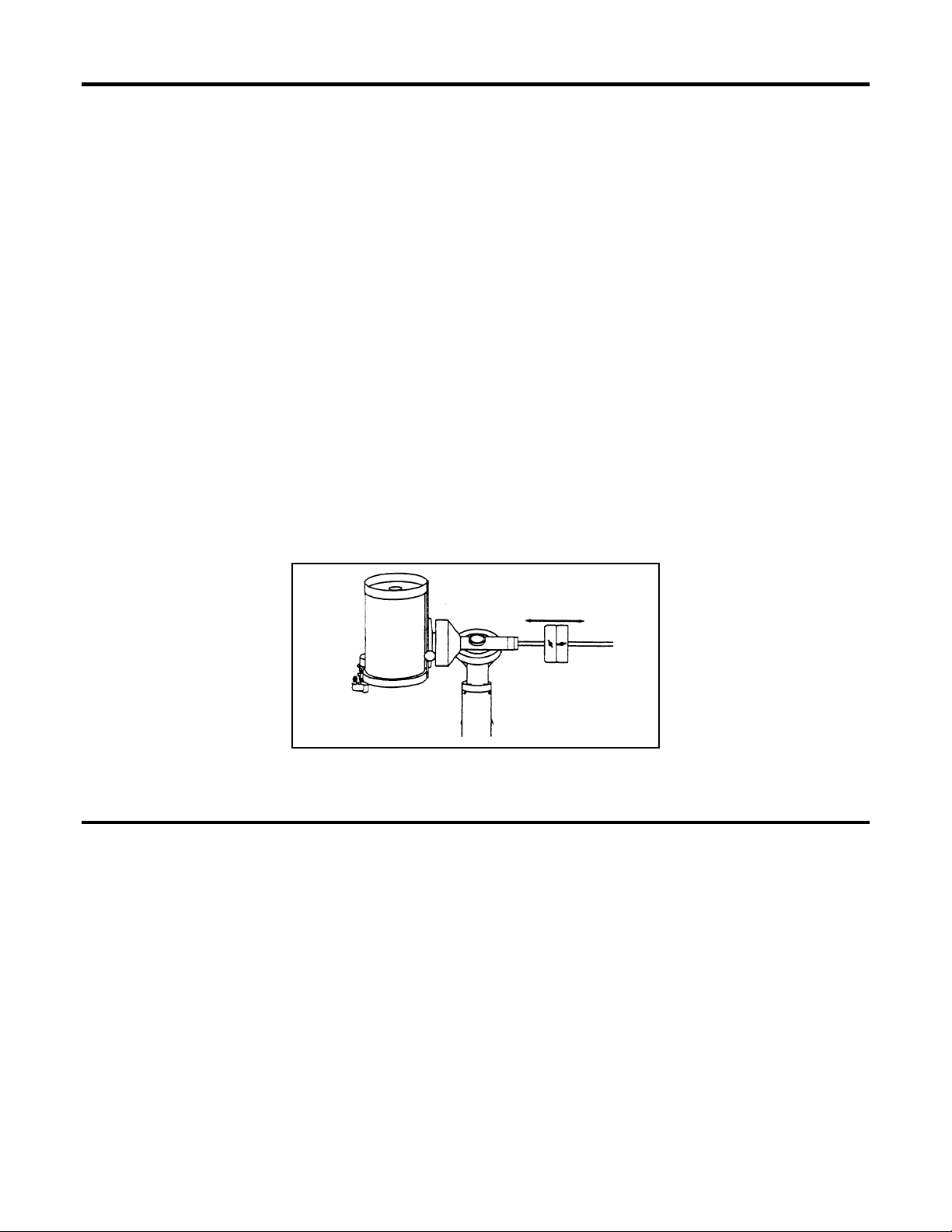
Attaching the Visual Back
The visual back is the accessory that allows you to attach all visual accessories to the telescope. The CGE 1400 comes with a
2" mirror diagonal that attaches directly to the optical tube without the use of a visual back. To attach the visual back:
1. Remove the plastic cover on the rear cell.
2. Place the knurled slip ring on the visual back over the threads on the rear cell.
3. Hold the visual back with the set screw in a convenient position and rotate the knurled slip ring clockwise until tight.
Once this is done, you are ready to attach other accessories, such as eyepieces, diagonal prisms, etc.
If you want to remove the visual back, rotate the slip ring counterclockwise until it separates from the rear cell.
9
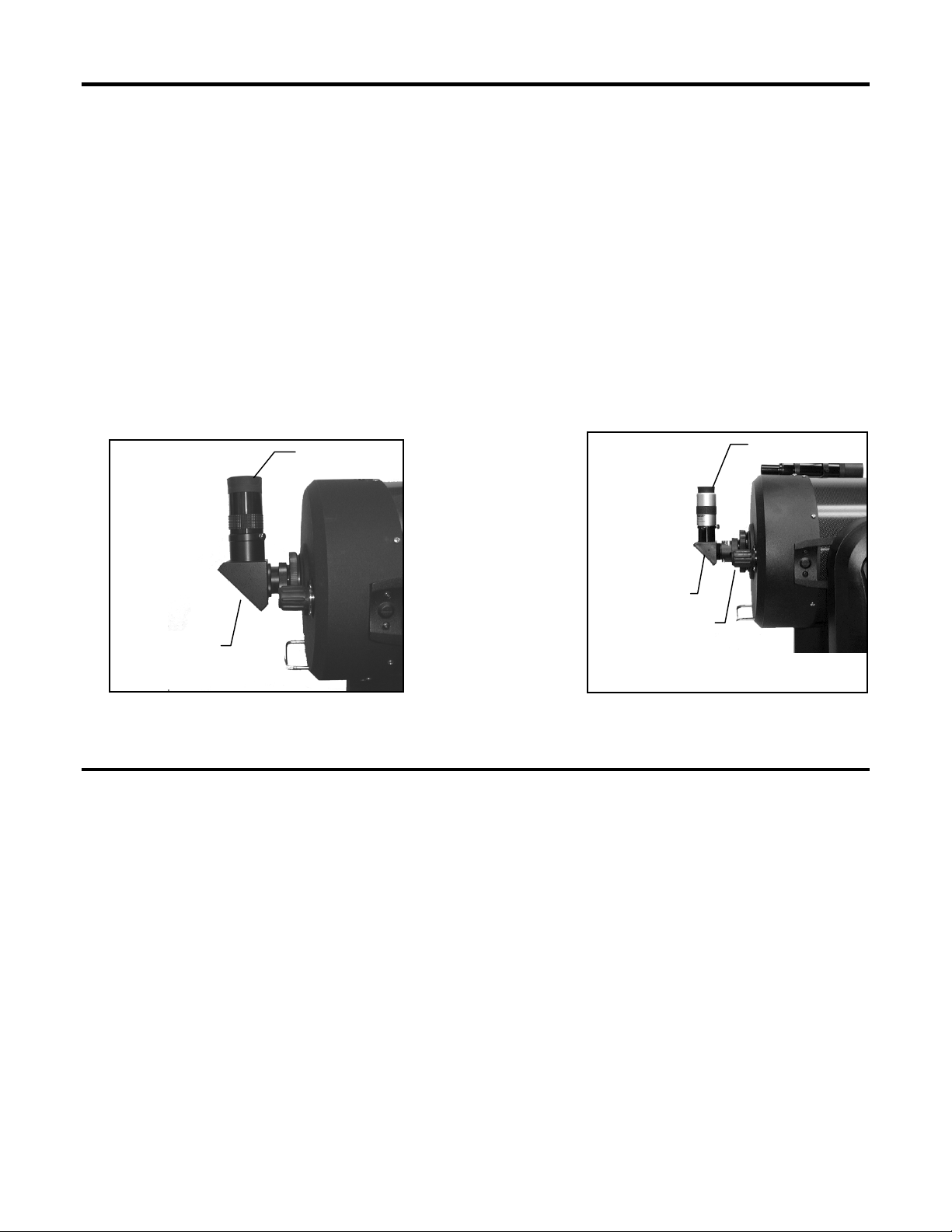
Installing the Star Diagonal
l
k
The star diagonal is a prism that diverts the light at a right angle to the light path of the telescope. This allows you to observe
in positions that are physically more comfortable than if you looked straight through. To attach the star diagonal onto a CGE
800, 925 or 1100:
1. Turn the set screw on the visual back until its tip no longer extends into (i.e., obstructs) the inner diameter of the visual back.
2. Slide the chrome portion of the star diagonal into the visual back.
3. Tighten the set screw on the visual back to hold the star diagonal in place.
If you wish to change the orientation of the star diagonal, loosen the set screw on the visual back until the star diagonal
rotates freely. Rotate the diagonal to the desired position and tighten the set screw.
The CGE 1400 comes with a 2" mirror diagonal that attaches directly onto the rear threads of the 14" optical tube. See figure
2-6.
2" Barrel
Eyepiece
Eyepiece
Star Diagona
Visual Bac
2" thread-on
Mirror Diagonal
Figure 2-6
Figure 2-7
Installing the Eyepiece
The eyepiece, or ocular, is an optical element that magnifies the image focused by the telescope. The eyepiece fits into either
the visual back directly, the star diagonal, or the 2" mirror diagonal. To install an eyepiece:
1. Loosen the set screw on the star diagonal until the tip no longer extends into the inner diameter of the eyepiece end
of the diagonal.
2. Slide the chrome portion of the eyepiece into the star diagonal.
3. Tighten the set screw on the star diagonal to hold the eyepiece in place.
To remove the eyepiece, loosen the set screw on the star diagonal and slide the eyepiece out. You can replace it with another
eyepiece (purchased separately).
NOTE: The 2" mirror diagonal has a 1 1/4" eyepiece adapter to use 1 1/4" eyepieces. You may remove the adapter to use 2"
eyepieces.
Eyepieces are commonly referred to by focal length and barrel diameter. The focal length of each eyepiece is printed on the
eyepiece barrel. The longer the focal length (i.e., the larger the number) the lower the eyepiece power and the shorter the
10
focal length (i.e., the smaller the number) the higher the magnification. Generally, you will use low-to-moderate power when
viewing. For more information on how to determine power, see the section on “Calculating Magnification.”
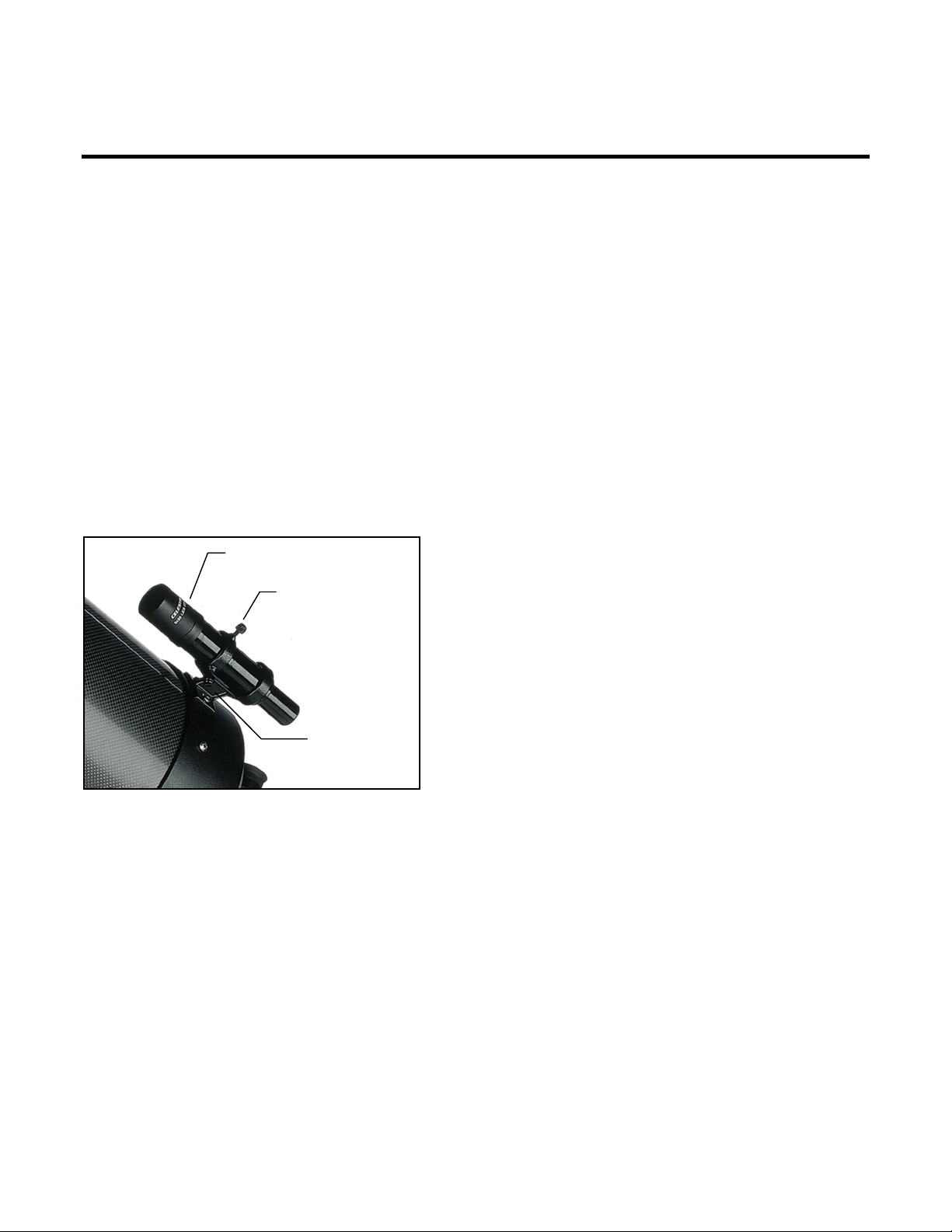
Installing the Finderscope
The CGE telescopes come with a 6x30 or 9x50 finderscope used to help you locate and center objects in the main field of
your telescope. To accomplish this, the finder has a built-in cross-hair reticle that shows the optical center of the finderscope.
Start by removing the finder and hardware from the plastic wrapper. Included are the following:
• Finderscope
• Finder Bracket
• Rubber O-ring
• Three Nylon Tipped Thumbscrews (10-24x1/2")
• Two Phillips Head Screws (8-32x1/2" or 10-24x1/2")
To install the finderscope:
1. Attach the bracket to the optical tube. To do this, place the curved portion of the bracket with the slot over the
two holes in the rear cell. The bracket should be oriented so that the rings that hold the finder are over the
telescope tube, not the rear cell (see Figure 2-8). Start threading the screws in by hand and tighten fully with an
Allen wrench.
Finderscope
Nylon
Adjustment
Screw
Finder Bracket
Figure 2-8
4. Rotate the finder until one cross hair is parallel to the R.A. axis and the other is parallel to the DEC axis.
5. Slide the eyepiece end of the finder into the front of the bracket.
6. Slightly tighten the three nylon tipped thumbscrews on the front ring of the bracket to hold the finder in place.
7. Once on, push the finder back until the O-ring is snug inside the back ring of the finder bracket.
8. Hand tighten the three nylon tipped thumbscrews until snug.
2. Partially thread-in the three nylon-tipped thumbscrews
that hold the finder in place inside the bracket. Tighten
the screws until the nylon heads are flush with the
inner diameter of the bracket ring. Do NOT thread
them in completely or they will interfere with the
placement of the finder. (Having the screws in place
when the finder is installed will be easier than trying to
insert the screws after the finder has been installed.)
3. Slide the rubber O-ring over the back of the finder (it
will NOT fit over the objective end of the finder). It
may need to be stretched a little. Once on the main
body of the finder, slide it up about one inch from the
end of the finder.
11
Moving the Telescope Manually
In order to properly balance your telescope, you will need to move your telescope manually at various portions of the sky to
observe different objects. To make rough adjustments, loosen the R.A. and DEC clutch knobs slightly and move the
telescope in the desired direction.
Both the R.A. and DEC axis have two knobs to clutch down each axis of the telescope. To loosen the clutches on the
telescope, rotate the clutch knobs counterclockwise. Rotate the clutch knobs on each axis clockwise to lock the telescope in
place.
Adjusting the Mount
In order for the clock drive to track accurately, the telescope’s axis of rotation
must be parallel to the Earth’s axis of rotation, a process known as polar
alignment. Polar alignment is achieved NOT by moving the telescope in
R.A. or DEC, but by adjusting the mount vertically, which is called altitude,
and horizontally, which is called azimuth. This section simply covers the
correct movement of the telescope during the polar alignment process. The
actual process of polar alignment, that is making the telescope’s axis of
rotation parallel to the Earth’s, is described later in this manual in the section
on “Polar Alignment.”
To adjust the mount in altitude:
Figure 2-9
1. Locate the altitude adjustment bolt just above the tripod column (see figure 2-10).
2. Using the 7/32" Allen wrench provided, turn the altitude adjustment bolt until the mount is at the right elevation.
The total altitude range is from 13° to 65°. With the 23 lb counterweight attached to the counterweight shaft, the equatorial
head can go as low as 20° without hitting the tripod leg.
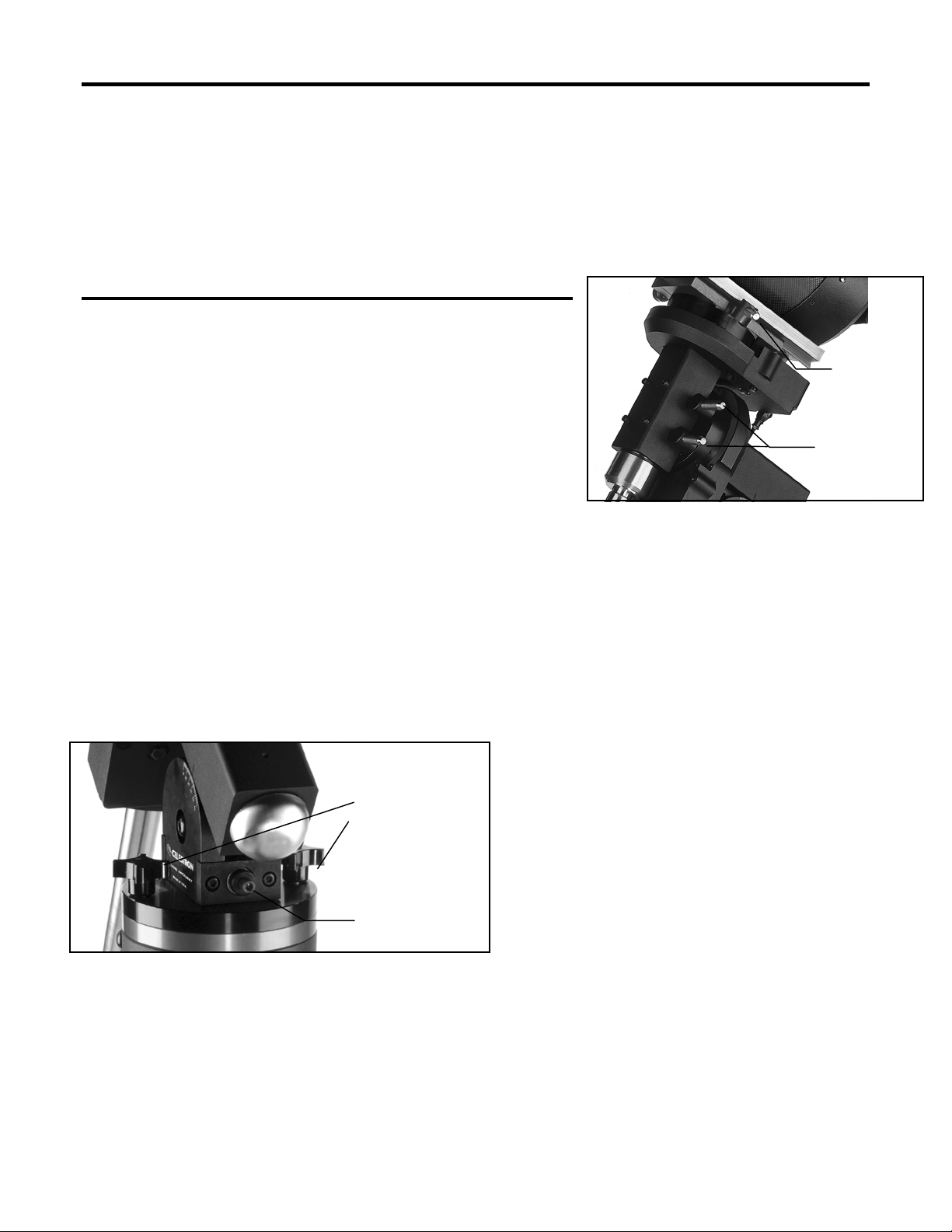
To adjust the mount in azimuth:
1. Locate the azimuth adjustment bolt on
the flat portion of the tripod column (see
figure 2-10).
Azimuth Lock
Knobs
2. Loosen the two azimuth lock knobs
located on the top of the tripod column.
3. Turn the azimuth adjustment bolt with
the 7/32" Allen wrench until the polar
axis is pointing in the right direction.
Altitude Adjustment
Bolt
4. Tighten the azimuth lock knobs to hold
the mount in place. The mount can be
moved ± 7° in azimuth using these bolts.
Helpful Hint: Located on the side of the equatorial mount head is a hole that serves as a convenient storage place for the
polar alignment Allen wrench. This will help prevent you from misplacing the tool when polar aligning in the field.
Keep in mind that adjusting the mount is done during the polar alignment process only. Once polar aligned, the mount must
NOT be moved. Pointing the telescope is done by moving the mount in right ascension and declination, as described earlier
in this manual. Once the appropriate adjustments have been made and you are aligned on the celestial pole, turn the clock
drive on and the telescope will track.
DEC Clutch
Knob
R.A. Clutch
Knobs
12
Balancing The Mount in R.A.
To eliminate undue stress on the mount, the telescope should be properly balanced around the polar axis. Proper balancing is
crucial for accurate tracking. To balance the mount:
1. Verify that the telescope securing knobs on the telescope mounting platform are tight.
2. Loosen the R.A. clutch knobs and position the telescope off to one side of the mount. The counterweight bar
will extend horizontally on the opposite side of the mount.
3. Release the telescope — GRADUALLY — to see which way the telescope “rolls.”
4. Loosen the set screws on the side of the counterweight so it can be moved the length of the counterweight bar.
5. Move the counterweight to a point where it balances the telescope (i.e., the telescope remains stationary when
the R.A. clutch knobs are loose).
6. Tighten the set screw on the counterweight to hold it in place.
While the above instructions describe a perfect balance arrangement, there should be a SLIGHT imbalance to ensure the best
possible tracking. When the scope is on the west side of the mount the counterweight should be slightly imbalanced to the
counterweight bar side. And when the tube is on the east side of the mount there should be a slight imbalance toward the
telescope side. This is done so that the worm gear is pushing against a slight load. The amount of the imbalance is very
slight. When taking astrophotographs, this balance process can be done for the specific area at which the telescope is
pointing to further optimize tracking accuracy.
Figure 2-11
Balancing The Mount in DEC
Although the telescope does not track in declination, the telescope should also be balanced in this axis to prevent any sudden
motions when the DEC clutch knob is loose. To balance the telescope in DEC:
1. Loosen the R.A. clutch knobs and rotate the telescope so that it is on one side of the mount (i.e., as described in
the previous section on “Balancing the Mount in R.A.”).
2. Tighten the R.A. clutch knobs to hold the telescope in place.
3. Loosen the DEC clutch knobs and rotate the telescope until the tube is parallel to the ground.
4. Release the tube — GRADUALLY — to see which way it rotates around the declination axis. DO NOT LET
GO OF THE TELESCOPE TUBE COMPLETELY!
13
r
5. Slightly loosen the knobs that holds the telescope to the mounting platform and slide the telescope either
forward or backward until it remains stationary when the DEC clutch is loose. Do NOT let go of the telescope
tube while the knob on the mounting platform is loose.
6. Tighten the knobs on the telescope mounting platform to hold the telescope in place.
Once the telescope is balanced in declination, slide the dovetail bar safety clamp down the front of the telescope's slide bar
until it touches the mounting platform and tighten the locking bolt. This not only acts as a safety in case the mounting
platform knobs are loosened, but will also allow you to put the tube on the mount in the exact same position each time for
perfect balance.
Like R.A. balance, these are general balance instructions and will reduce undue stress on the mount. When taking
astrophotographs, this balance process should be done for the specific area at which the telescope is pointing.
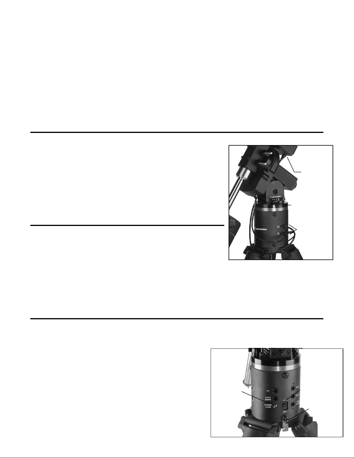
Attaching the Motor Cables
The CGE mount comes with two power cables to connect each drive motor to the
electronics pier. To attach the motor cables:
1. Locate the Declination cable (the longer cable) and plug one end of the
cable into the port on the electronics pier labeled DEC Port and plug the
other end of the cable into the port located on the bottom of the
declination motor (see figure2-12).
2. Locate the R.A. cable (the shorter cable) and plug one end of the cable
into the port on the electronics pier labeled RA Port and plug the other
end of the cable into the port located on the bottom of the right ascension
motor (see figure2-12).
Cable to DEC
Motor
Cable to R.A.
Motor
Powering the Telescope
Motor Ports
The CGE can be powered by the supplied car battery adapter or optional 12v AC.
Use only the adapter supplied by Celestron. Using any other adapter may damage
the electronics and will void your manufacturer's warranty.
Figure 2-12
1. To power the CGE with the car battery adapter (or 12v AC adapter), simply plug the round post into the 12v outlet
on the electronic pier and plug the other end into your cars cigarette lighter outlet or portable power supply (see
Optional Accessories). Note: to prevent the power cord from being accidentally pulled out, wrap the power cord
around the strain relief located below the power switch.
2. Turn on the power to the CGE by flipping the switch, located in the center of the pier, to the "On" position.
Transporting the CGE
Because of the Celestron CGE telescope size and weight, you should ALWAYS remove the telescope from the mount when
moving the telescope. To do so:
1. Take the telescope off of the mount and return it to its
shipping box.
2. Remove the counterweight from the counterweight bar.
3. Remove the counterweight bar from the mount.
4. Remove the finderscope from the optical tube.
5. Take the equatorial mount off of the central column.
12v DC Powe
On/Off Switch
Power Cord
Strain Relief
14
Figure 2-13

6. Remove the center leg brace from the tripod.
7. Collapse the tripod legs inward, towards each other.
The telescope is now broken down into enough pieces to be easily transported.
Note: Before transporting the optical tube it is recommended that the two mirror locking screw located on the rear cell of the
tube be locked down. Before tightening the screws, the primary mirror must be moved towards the rear cell of the tube.
Rotate the focuser knob clockwise until you feel a slight resistance. The screws should now thread into the primary mirror
mounting plate.
When not in use, your CGE telescope can be left fully assembled and set up. However, all lens and eyepiece covers should
be put back in place. This will reduce the amount of dust build-up on all optical surfaces and reduce the number of times you
need to clean the instrument. You may want to return everything to its original shipping container and store it there. If this is
the case, all optical surfaces should still be covered to prevent dust accumulation.
15
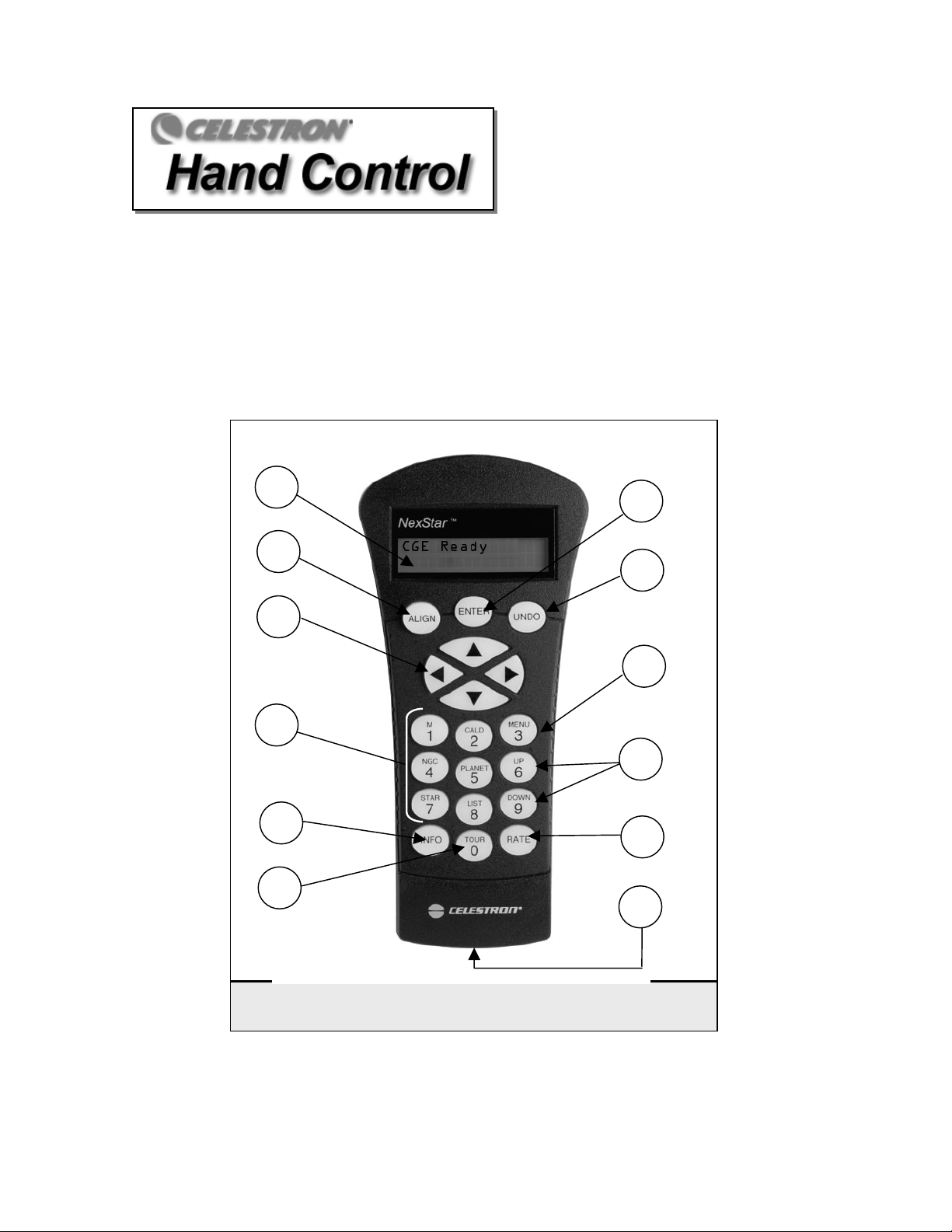
The CGE has a hand controller designed to give you instant access to all the functions the CGE has to offer.
With automatic slewing to over 40,000 objects, and common sense menu descriptions, even a beginner can
master its variety of features in just a few observing sessions. Below is a brief description of the individual
components of the computerized hand controller:
1. Liquid Crystal Display (LCD) Window: Has a dual-line, 16 character display screen that is backlit
for comfortable viewing of telescope information and scrolling text.
2. Align: Instructs the CGE to use a selected star or object as an alignment position.
3. Direction Keys: Allows complete control of the CGE in any direction. Use the direction keys to move
the telescope to the initial alignment stars or for centering objects in the eyepiece.
1
7
2
8
3
9
4
10
5
11
6
12
Figure 3-1
The CGE Hand Control
16

4. Catalog Keys: The CGE has keys on the hand control to allow direct access to each of the catalogs in
its database. The CGE contains the following catalogs in its database:
Messier – Complete list of all Messier objects.
NGC – Complete list of all the deep-sky objects in the Revised New General Catalog.
Caldwell – A combination of the best NGC and IC objects.
Planets - All 8 planets in our Solar System plus the Moon.
Stars – A compiled list of the brightest stars from the SAO catalog.
List – For quick access, all of the best and most popular objects in the CGE database have been
broken down into lists based on their type and/or common name:
Named Stars
Named Objects
Double Stars
Variable Stars
Asterisms
CCD Objects
IC Objects
Abell Objects
Constellation
5. Info: Displays coordinates and useful information about objects selected from the CGE database.
6. Tour: Activates the tour mode, which seeks out all the best objects for the current date and time, and
automatically slews the CGE to those objects.
7. Enter: Pressing Enter allows you to select any of the CGE functions and accept entered parameters.
8. Undo: Undo will take you out of the current menu and display the previous level of the menu path.
Press Undo repeatedly to get back to a main menu or use it to erase data entered by mistake.
9. Menu: Displays the many setup and utilities functions such as tracking rate and user defined objects
and many others.
10. Scroll Keys: Used to scroll up and down within any of the menu lists. A double-arrow will appear on
the right side of the LCD when there are sub-menus below the displayed menu. Using these keys will
scroll through those sub-menus.
11. Rate: Instantly changes the rate of speed of the motors when the direction buttons are pressed.
12. RS-232 Jack: Allows you to interface with a computer and control the CGE remotely.
Hand Control Operation
This section describes the basic hand control procedures needed to operate the CGE. These procedures are
grouped into three categories: Alignment, Setup and Utilities. The alignment section deals with the initial
telescope alignment as well as finding objects in the sky; the setup section discusses changing parameters such
as tracking mode and tracking rate; finally, the last section reviews all of the utilities functions such as the
calibrating your mount, PEC and backlash compensation.
Common name listing of the brightest stars in the
sky.
Alphabetical listing of over 50 of the most popular
deep sky objects.
Numeric-alphabetical listing of the most visually
stunning double, triple and quadruple stars in the
sky.
Select list of the brightest variable stars with the
shortest period of changing magnitude.
A unique list of some of the most recognizable star
patterns in the sky.
A custom list of many interesting galaxy pairs, trios
and clusters that are well suited for CCD imaging
with the CGE telescope.
A complete list of all the Index Catalog deep-sky
objects.
A custom list of the Abell Catalog deep-sky
galaxies.
A complete list of all 88 constellations.
17
t
r
r
A
Alignment Procedures
In order for the CGE to accurately point to objects in the sky, it must first be aligned to two known positions
(stars) in the sky. With this information, the telescope can create a model of the sky, which it uses to locate any
object with known coordinates. There are many ways to align the CGE with the sky depending on what
information the user is able to provide: Auto Two Star Alignment allows the user to select two stars and uses
the entered time/location information to align the telescope; Auto One-Star Alignment involves the same
process as Two-Star Align, however only uses one star position to align the telescope mount. Quick-Align will
ask you to input all the same information as you would for the Auto Align procedure. However, instead of
slewing to two alignment stars for centering and alignment, the telescope bypasses this step and simply models
the sky based on the information given. Finally, Last Alignment restores your last saved star alignment and
switch position. Last Alignment also serves as a good safeguard in case the telescope should lose power.
Startup Procedure
Before any of the described alignments are performed, the
CGE needs to first index its switch position so that each axis
has an equal amount of travel to move in either direction. It is a
good idea to calibrate your mounts switch position after a
successful alignment (see Calibrating the CGE Mount box on
this page). Once the switch position has been set, the hand
control will display the last entered date and time information
stored in the hand control. Once the CGE is powered on:
1. Press ENTER begin the alignment process.
2. Press ENTER again to set the telescopes switch
position. Press UNDO if you would like to manually
move the telescope to a different switch position. This
is useful if using your scope with additional
equipment attached and its range of motion is limited.
3. After the telescope moves to its switch position, the
hand control will display the last entered local time,
date, time zone, longitude and latitude.
• Use the Up/Down keys (10) to view the
current parameters.
• Press ENTER to accept the current
parameters.
• Press UNDO to enter current date and time
information into the hand control. The
following information will be displayed:
Time - Enter the current local time for your area.
You can enter either the local time (i.e. 08:00), or
you can enter military time (i.e. 20:00 ).
• Select PM or AM. If military time was
entered, the hand control will bypass this
step.
• Choose between Standard time or Daylight
Savings time. Use the Up and Down scroll
buttons (10) to toggle between options.
• Select the time zone that you are observing
from. Again, use the Up and Down buttons
Calibrating the CGE Mount
In order to improve the pointing accuracy of your
CGE telescope, the internal declination axis switch
needs to be properly calibrated. This improves the
pointing accuracy in two ways: First it measures and
records the offset error when the declination switch
is found at start-up. Second, it calculates and
compensates for "cone" error inherent in all German
equatorial mounts. Cone error is the inaccuracy tha
results from the optical tube not being perpendicula
to the mounts declination axis. The mount should
always be calibrated the first time it is used and only
needs to be re-calibrated if the mount is used with a
different optical tube or the optical tube is subjected
to rough handling.
Calibrating the mount is a very easy process and
takes only a minute to do. To calibrate your CGE
mount:
• First, you must complete an Auto Two-Sta
lignment as described in this section.
However, you must take special notice to
select two alignment stars that are on the same
side of the Meridian (i.e. both in the western
half of the sky or both in the eastern half of the
sky). See Figure 3-2.
• Once you have completed a successful
alignment, slew to a known star that is on the
other side of the Meridian from your two original
alignment stars.
• Press UNDO until CGE Ready is displayed.
Press the MENU button on the hand control and
select Calibrate Mount from the Utilities menu.
• Scroll down to DEC Switch / Cone and press
ENTER to begin the calibration. When the
display asks you to center your calibration star,
carefully center the star in the eyepiece making
sure to use the Up and Right arrows keys to
remove any of the backlash in the gears. Press
ENTER to complete the calibration process.
This calibration offset will be stored and used to
improve the accuracy of future alignments.
18
O
bserving
y
Tip
(10) to scroll through the choices. Refer to Time Zone map in Appendix for more
information.
• Date - Enter the month, day and year of your observing session.
• Finally, you must enter the longitude and latitude of the location of your observing site.
Use the table in Appendix C to locate the closest longitude and latitude for your current
observing location and enter those numbers when asked in the hand control, pressing ENTER
after each entry. Remember to select "West" for longitudes in North America and "North" for
latitudes in the North Hemisphere. For international cities, the correct hemisphere is indicated
in the Appendix listings.
4. Select one of the four alignment methods as described below.
Auto Two-Star Align
Auto Two-Star Align allows the user to select two stars on which to align the telescope. To Auto Align your
telescope:
1. Select Auto Two-Star from the alignment choices given. Based on the date and time information
entered, the CGE will automatically select and display a bright star that is above the horizon.
• Press ENTER to select this star as your first alignment star.
• If for some reason the chosen star is not visible (perhaps behind a tree or building) press UNDO
to have the hand control automatically select the next brightest star.
• Or you can use the Up/Down keys to browse the entire Named Star list and select any one of
over two hundred alignment stars.
2. Once the telescope is finished slewing to your first
alignment star, the display will ask you to use the arrow
buttons to align the selected star with the cross hairs in the
center of the finderscope. When centered in the finder, press
ENTER.
3. The display will then instruct you to center the star in the
field of view of the eyepiece. When the star is centered,
press ALIGN to accept this star as your first alignment star.
4. After the first alignment star has been entered the CGE will
automatically select a second alignment star and have you
repeat this procedure for that star. When the telescope has
been aligned on both stars the display will read
Alignment Successful, and you are now ready to
find your first object.
For the best possible pointing accuracy, always center the alignment
stars using the up arrow button and the right arrow button.
Approaching the star from this direction when looking through the
eyepiece will eliminate much of the backlash between the gears and
assure the most accurate alignment possible.
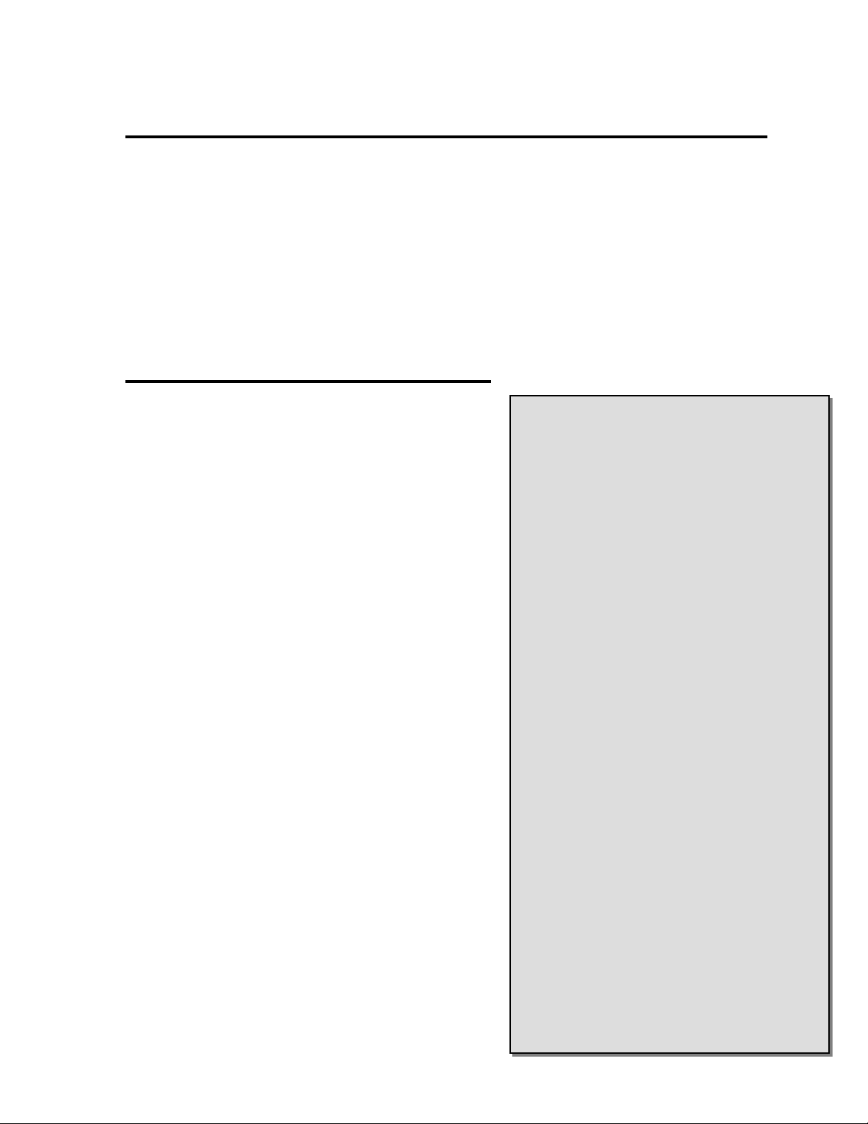
The Meridian is an imaginary line in the sk
that starts at the North celestial pole and
ends at the South celestial pole and passes
through the zenith. If you are facing South,
the meridian starts from your Southern
horizon and passes directly overhead to the
North celestial pole.
Figure 3-2
Auto One-Star Align
Auto One-Star Alignment works much the same way as Auto Two-Star Align but uses only a single star in the
sky for alignment. This method of alignment is not as accurate as the two-star alignment and is recommended
only for telescopes that are permanently and accurately polar aligned.
19

Quick-Align
Quick-Align uses all the date and time information entered at startup to align the telescope. However, instead of slewing to
two alignment stars for centering and alignment, the CGE bypasses this step and simply models the sky based on the
information given. This will allow you to roughly slew to the coordinates of bright objects like the moon and planets and
gives the CGE the information needed to track objects in altazimuth in any part of the sky. Quick-Align is not meant to be
used to accurately locate small or faint deep-sky objects or to track objects accurately for photography.
To use Quick-Align, simply select Quick Align from the alignment options and press ENTER. The CGE will automatically
use the entered date/time parameters to align itself with the sky and display Alignment Successful.
Note: Once a Quick-Align has been done, you can use the Re-alignment feature (see next page) to improve your
telescopes pointing accuracy.
Last Alignment
The CGE Last Alignment method will automatically recall the last saved mount switch positions, longitude and
latitude along with the current date and time given from the real time clock, to continue using the alignment that
was saved when the telescope was last powered down. This is a useful feature should your telescope
accidentally lose power or be powered down.
Note: Just like with Quick-Align, you can use the Re-alignment feature (see next page) to improve your
telescopes pointing accuracy after using the Last Alignment method. To maintain a more accurate alignment
over a series of observing sessions, use the Hibernate feature described later in this chapter.
CGE Re-Alignment
The CGE has a re-alignment feature which allows you to replace either of the two original alignment
stars with a new star or celestial object. This can be useful in several situations:
• If you are observing over a period of a few hours, you may notice that your original two alignment
stars have drifted towards the west considerably. (Remember that the stars are moving at a rate of
15º every hour). Aligning on a new star that is in the eastern part of the sky will improve your
pointing accuracy, especially on objects in that part of the sky.
• If you have aligned your telescope using the Quick-Align method, you can use re-align to align to
two actual objects in the sky. This will improve the pointing accuracy of your telescope without
having to re-enter addition information.
To replace an existing alignment star with a new alignment star:
1. Select the desired star (or object) from the database and slew to it.
2. Carefully center the object in the eyepiece.
3. Once centered, press the UNDO button until you are at the main menu.
4. With CGE Ready displayed, press the ALIGN key on the hand control.
5. The display will then ask you which alignment star you want to replace. Use the UP and Down scroll
keys to select the alignment star to be replaced. It is usually best to replace the star closest to the new
object. This will space out your alignment stars across the sky.
6. Press ALIGN to make the change.
20

Helpful
Hint
Object Catalog
Selecting an Object
Now that the telescope is properly aligned, you can choose an object from any of the catalogs in the CGE's
extensive database. The hand control has a key (4) designated for each of the catalogs in its database. There are
two ways to select objects from the database: scrolling through the named object lists and entering object
numbers.
Pressing the LIST key on the hand control will access all objects in the database that have common names
or types. Each list is broken down into the following categories: Named Stars, Named Object, Double
Stars, Variable Stars, Asterisms and CCD Objects. Selecting any one of these catalogs will display a
numeric-alphabetical listing of the objects under that list. Pressing the Up and Down keys (10) allows you
to scroll through the catalog to the desired object.
When scrolling through a long list of objects, holding down either the Up or Down key will allow you to scroll
through the catalog more rapidly by only displaying every fifth catalog object.
Pressing any of the other catalog keys (M, CALD, NGC, or STAR) will display a blinking cursor below the
name of the catalog chosen. Use the numeric key pad to enter the number of any object within these
standardized catalogs. For example, to find the Orion Nebula, press the "M" key and enter "042".
Slewing to an Object
Once the desired object is displayed on the hand control screen, choose from the following options:
• Press the INFO Key. This will give you useful information about the selected object such as
R.A. and declination, magnitude size and text information for many of the most popular objects.
• Press the ENTER Key. This will automatically slew the telescope to the coordinates of the
object.
Caution: Never slew the telescope when someone is looking into the eyepiece. The telescope can move at fast slew
speeds and may hit an observer in the eye.
Object information can be obtained without having to do a star alignment. After the telescope is powered on,
pressing any of the catalog keys allows you to scroll through object lists or enter catalog numbers and view the
information about the object as described above.
Finding Planets
The CGE can locate all 8 of our solar systems planets plus the Moon. However, the hand control will only
display the solar system objects that are above the horizon (or within its filter limits). To locate the planets,
press the PLANET key on the hand control. The hand control will display all solar system objects that are
above the horizon:
• Use the Up and Down keys to select the planet that you wish to observe.
• Press INFO to access information on the displayed planet.
• Press ENTER to slew to the displayed planet.
21

Tour Mode
The CGE includes a tour feature which automatically allows the user to choose from a list of interesting objects
based on the date and time in which you are observing. The automatic tour will display only those objects that
are within your set filter limits (see Filter Limits in the Setup Procedures section of the manual). To activate
the Tour mode, press the TOUR key (6) on the hand control. The CGE will display the best objects to observe
that are currently in the sky.
• To see information and data about the displayed object, press the INFO key.
• To slew to the object displayed, press ENTER.
• To see the next tour object, press the Up key.
Constellation Tour
In addition to the Tour Mode, the CGE telescope has a Constellation Tour that allows the user to take a tour of
all the best objects in each of the 88 constellations. Selecting Constellation from the LIST menu will display all
the constellation names that are above the user defined horizon (filter limits). Once a constellation is selected,
you can choose from any of the database object catalogs to produce a list of all the available objects in that
constellation.
• To see information and data about the displayed object, press the INFO key.
• To slew to the object displayed, press ENTER.
• To see the next tour object, press the Up key.
Direction Buttons
The CGE has four direction buttons (3) in the center of the hand control which control the telescope's motion in
altitude (up and down) and azimuth (left and right). The telescope can be controlled at nine different speed
rates.
Rate Button
Pressing the RATE key (11) allows you to instantly change the speed rate of the motors from high speed slew
rate to precise guiding rate or anywhere in between. Each rate corresponds to a number on the hand controller
key pad. The number 9 is the fastest rate (4º per second, depending on power source) and is used for slewing
between objects and locating alignment stars. The number 1 on the hand control is the slowest rate (.5x
sidereal) and can be used for accurate centering of objects in the eyepiece and photographic guiding. To
change the speed rate of the motors:
• Press the RATE key on the hand control. The LCD will display the current speed rate.
• Press the number on the hand control that corresponds to the desired speed. The number
will appear in the upper-right corner of the LCD display to indicate that the rate has been
changed.
The hand control has a "double button" feature that allows you to instantly speed up the motors without having
to choose a speed rate. To use this feature, simply press the arrow button that corresponds to the direction that
you want to move the telescope. While holding that button down, press the opposite directional button. This
will increase the slew rate to the maximum slew rate.
When pressing the Up and Down arrow buttons in the slower slew rates (6 and lower) the motors will move the
telescope in the opposite direction than the faster slew rates (7 thru 9). This is done so that an object will move
in the appropriate direction when looking into the eyepiece (i.e. pressing the Up arrow button will move the star
22
up in the field of view of the eyepiece). However, if any of the slower slew rates (rate 6 and below) are used to
N
center an object in the finderscope, you may need to press the opposite directional button to make the telescope
move in the correct direction.
1 = .5x 6 = 64x
2 = 1x (sidereal) 7 = .5º / sec
3 = 4x 8 = 2º / sec
4 = 8x 9 = 4º / sec
5 = 16x
ine available slew speeds
Setup Procedures
The CGE contains many user defined setup functions designed to give the user control over the telescope's
many advanced features. All of the setup and utility features can be accessed by pressing the MENU key and
scrolling through the options:
Tracking Mode This allows you to change the way the telescope tracks depending on the type of
mount being used to support the telescope. The CGE has three different tracking
modes:
EQ North
EQ South
Off
Tracking Rate In addition to being able to move the telescope with the hand control buttons, the
CGE will continually track a celestial object as it moves across the night sky. The
tracking rate can be changed depending on what type of object is being observed:
Sidereal
Lunar
Solar
View Time-Site - Displays the current time and longitude/latitude downloaded from the optional CN-16 GPS
receiver. It will also display other relevant time-site information like time zone, daylight saving and local
Used to track the sky when the telescope is polar aligned in the
Northern Hemisphere.
Used to track the sky when the telescope is polar in the Southern
Hemisphere.
When using the telescope for terrestrial (land) observation, the
tracking can be turned off so that the telescope never moves.
This rate compensates for the rotation of the Earth by moving the
telescope at the same rate as the rotation of the Earth, but in the
opposite direction. When the telescope is polar aligned, this can
be accomplished by moving the telescope in right ascension only.
When mounted in Alt-Az mode, the telescope must make
corrections in both R.A. and declination.
Used for tracking the moon when observing the lunar landscape.
Used for tracking the Sun when solar observing.
23
 Loading...