

Page 1
MV 2 UL AF
NS12A
OPERATOR’S MANUAL
Page 2

Page 3

MV 2 UL AF
TABLE OF CONTENTS
1 TECHNICAL CHARACTERISTICS ................................................................................. 4
2 INTRODUCTION ............................................................................................................. 4
3 INSTALLATION ............................................................................................................... 4
4 TO OPERATE SAFELY .................................................................................................. 4
5 OPERATING PROCEDURES ......................................................................................... 5
5. 1 DESCRIPTION OF CONTROLS ............................................................................ 5
5. 2 OPERATION HELPFUL HINTS ............................................................................. 6
5. 3 CLEANING AND SANITIZING PROCEDURES ..................................................... 6
5. 3. 1 DISASSEMBLY ........................................................................................... 6
5. 3. 2 CLEANING .................................................................................................. 7
5. 3. 3 SANITIZING ................................................................................................ 8
5. 3. 4 ASSEMBLY ................................................................................................. 8
5. 4 IN-PLACE SANITIZATION ..................................................................................... 8
6 ROUTINE MAINTENANCE ............................................................................................. 9
6. 1 MAINTENANCE
(TO BE CARRIED OUT BY QUALIFIED SERVICE PERSONNEL ONLY) ...... 9
7 DEFROST TIMER ........................................................................................................... 9
8 AUTOFILL SYSTEM ....................................................................................................... 9
8. 1 INSTALLATION .................................................................................................... 10
8. 2 OPERATING PROCEDURES .............................................................................. 10
8. 2. 1 DESCRIPTION OF CONTROLS .............................................................. 10
8. 2. 2 OPERATIONAL HELPFUL HINTS ........................................................... 11
8. 2. 3 IN-PLACE SANITIZATION ........................................................................ 11
8. 3 ROUTINE MAINTENANCE .................................................................................. 11
This dispenser is manufactured under one or more of the following U.S.patents and/or other pending patents
U.S.A. 4,900,158
U.S.A. 4,696,417
U.S.A. 5,713,214
U.S.A. 5,906,105
3
Page 4
MV 2 UL AF
1 TECHNICAL CHARACTERISTICS
Transparent removable bowls n 2
Capacity of each bowl, approx . Gal 2.5
Dimensions:
width Inches 14.25
depth Inches 18.5
height Inches 35.75
Net weight, approx. Lbs 143
Gross weight, approx. Lbs 147
Adjustable thermostats n 2
Hermetic compressors n 2
Air-cooled condensers n 2
Overload protectors n 2
Safety pressure switches n 2
Noise level lower than 70 dB (A)
IMPORTANT
Read electrical ratings written on the data pla te of the
individual units; the data plate is adhered on the dispensing
side panel of the unit, just behind the drip tray (the right side
drip tray in multiple bowl models). The serial number of the
unit (preceded by the symbol #) is adhered inside the left
switch box. Data plate specifications will always sup ersede
the information in this manual.
file a claim.
3 - Install the unit on a counter top that will support the combi-
ned weight of dispenser and product bearing in mind
what is stated in the preceding point 1 IMPORTANT
warning.
4 - A minimum of 15 cm (6”) of free air space all around the
unit should be allowed to guarantee adequate ventilation.
5 - The standard legs originally installed must be replaced by
the rubber base available in the unit package. To install the
rubber base unscrew the standard legs and fix the rubber
base using the four screws included in the package.
6 - Bef ore plugging the unit in, check if the voltage is the same
as that indicated on the data plate. Plug the unit into a
grounded, protected single phase electrical supply according to the applicable electrical codes and the specifications of your machine. When the unit has no plug, install a
proper grounded plug, in compliance with electrical codes
in force in your area, suitable to at least 10 Amp 250 Volt
(220-230 Volts 50-60 Hz areas) and 20 Amp 250 Volt
(100-115 Volts 50-60 Hz areas) applications. Should you
prefer to connect the unit directly to the mains, connect the
supply cord to a 2-pole wall breaker, whose contact ope-
ning is at least 0.125”. Do not use extension cords.
ATTENTION
Failure to provide proper electrical ground ac cording to
applicable electrical codes could result in serious
shock hazard.
7 - The unit doesn’t come presanitized from the factory.
Before serving products, the dispenser must be disassembled, cleaned and sanitized according to this handbook
instructions (chapter 5.3 CLEANING AND SANITAZING
PROCEDURES).
The electric diagram of the dispenser is located in the inner part
of the dispensing side panel.
Specifications are subject to change without notice.
2 INTRODUCTION
Please read all sections of this manual thoroughly to familiarize
yourself with all aspects of the unit.
Like all mechanical products, this machine will require cleaning
and maintenance. Besides, dispenser working can be
compromised by operator’s mistakes during disassembly an d
cleaning. It is strongly recommended that personnel
responsible for the equipment’s daily operations, disassembly,
cleaning, sanitizing and assembly, go through thes e
procedures in order to be properly trained and to make sure
that no misunderstandings exist.
3 INSTALLATION
1 - Remove the corrugate container and packing materials
and keep them for possible future use.
IMPORTANT
When handling the machine never grasp it by the bowls
or by the evaporator cylinders. The manufacturer
refuses all responsibilities for possible damages which
may occur through incorrect handling.
2 - Inspect the uncrated unit for any possible damage. If
damage is found, call the delivering carrier immediately to
4 TO OPERATE SAFELY
1 - Do not operate the d ispenser without reading this opera-
tor’s manual.
2 - Do not operate the dispenser unless it is prope rly groun-
ded.
3 - Do not use extension cords to connect the dispenser.
4 - Do not operate the dispenser unless all panels are restrai-
ned with screws.
5 - Do not obstruct air intake and discharge openings: 15 cm
(6”) minimum air space all around the dispenser.
6 - Do not put objects or fingers in pane ls louvers and faucet
outlet.
7 - Do not remove bowls, augers and panels for clea ning or
routine maintenance unless the dispenser is disconnected
from its power source.
5 OPERATING PROCEDURES
1 - Clean and sanitize the unit accordi ng to the instruction s in
this manual. See chapter 5.3 CLEANING AND SANITI-
ZING PROCEDURES.
2 - Fill the bowls with product to the maximum level mark. Do
not overfill.
The exact quantity of product (expressed as liters and ga l-
lons) is shown by marks on the bowl.
3 - In case of products to be diluted with water, pour water into
bowl first, then add correct quantity of product. In case of
natural squashes, it is advisable to strain them, in order to
prevent pulps from obstructing the faucet outlet.
4 - To obtain the best performance and result, use bases
designed to be run in Granita freezers. Such bases have a
sugar content of 34 degrees Baumé corresponding to 64
degrees Brix (equivalent to a specific grav ity of about 2.8
lb./0.25 gal).
For Granita the bases are to be diluted with water on a 1
plus 4/4.5 basis.
4
Page 5
MV 2 UL AF
For soft drinks the bases are to be diluted with more water,
on a 1 plus 5/5.5 basis.
In any case follow the syrup manufacturer’s instructions for
both Granita and soft drink recipes.
If natural juices (e.g. lemon, orange) as well as sugarless
products (e.g. coffee) are us ed, dissolve 5.3 - 7 oz. of
sugar per 0.25 gallons.
IMPORTANT
However Granita mix may be done, its Brix (sugar
percent content) must be at least 13.
5 - Install the covers and check that they are correctly placed
over the bowls. There must be a correct electrical connection between the bowl and the cover.
6 - Set the control switches as shown in chapter
5.1 DESCRIPTION OF CONTROLS.
7 - Always leave the dispenser on, as the refrigeration stops
automatically when Granita reaches the proper thickness.
The mixers will continue to turn.
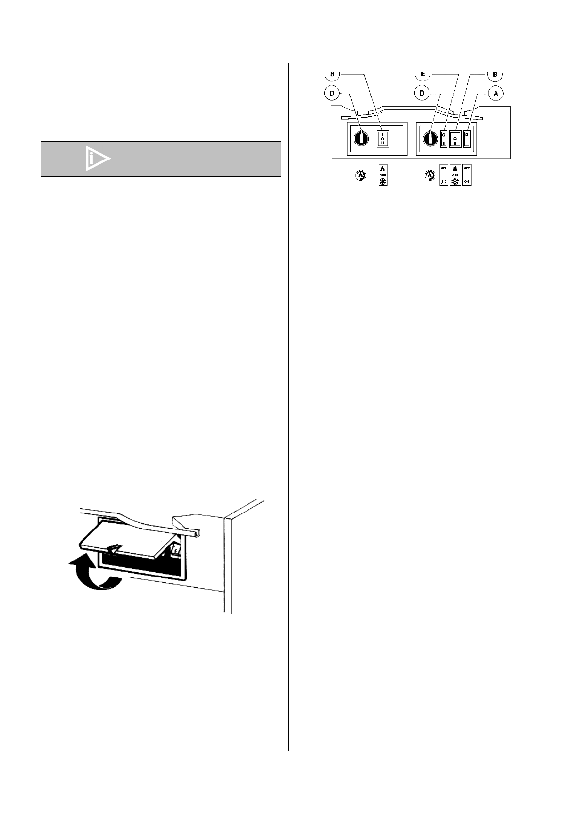
5. 1 DESCRIPTION OF CONTROLS
follows:
figure 2
Power switch (A)
0 position : power is turned OFF to all functions.
I position : power is turned ON to all functions and the
other switches are enabled. The fan motor
runs.
Light switch (E)
0 position : all top cover lights are OFF.
I position : all top cover lights are ON, provided that
power switch (A) is set to I.
The dispenser is equipped with a p ower switch and a light
switch. In addition each bowl is individually operated by a
mixer/refrigeration switch. In fact it is possible to dispense both
soft drinks and Granita.
When a bowl is in Soft Drink mode the beverage temperature
is controlled by the corresponding thermostat.
When a bowl is in Granita mode the mix viscos ity is co ntrolle d
by the corresponding adjustment screw located in the rear wall
of each container (for temperature and viscosity setting make
reference to chapter 5.2 OPERATION HELPFUL HINTS).
All the switches are located on the faucet side of the dispenser
in switch panels protected by switch covers (see figure 1).
figure 1
In addition the dispenser is equipped with automatic safety
pressure switches to prevent damages to the compressors.
The lighting of the warning light at the left of the switch covers
means insufficient ventilation of the unit. In this case check that
all around the dispenser there is sufficient space for ventilation,
at least 15 cm (6”) on each side and that condenser filter is free
from dust or other obstructions.
In case the warning light is still ON even after these operations
have been carried out, Service call is required.
With reference to figure 3 dispenser controls functions are as
Mixer/refrigeration switch (B)
I position : mixer and refrigeration ON.
SOFT DRINK mode.
0 position : OFF.
II position : mixer and refrigeration ON.
GRANITA mode.
Thermostat (D)
Turn clockwise : to decrease temperature
Turn counterclockwise : to increase temperature
To operate the unit:
1 - Set the power switch to I position.
2 - Set the mixer/refrigeration switches as follows:
- to the I position to get soft drink.
- to the II position to get Granita.
3 - Set the light switch to I position.
5. 2 OPERATION HELPFUL HINTS
1 - Granita viscosity adjustment : proper Granita viscosity is
factory preset. To change the viscosity, if needed, use a
standard screwdriver to turn the adjustment screw located
in the rear wall of each container as follows (see figure 3):
- toward right (clockwise) to obtain a thicker product (the
indicator F will go down in opening G).
- toward left (counterclockwise) to obtain a thinner product
5
Page 6

MV 2 UL AF
(the indicator F will go up in opening G).
figure 3
2 - Beverage temperature adjustment: proper beverage
temperature is factory preset. To reset, turn the knob located in each switch box as follows:
- toward right (clockwise) to decrease temperature.
-toward left (counterclockwise) to increase temperature.
Note: beverage temperature is controlled by the thermostat only when the mixer/refrigeration switch(es)
are in I position, Soft Drink mode.
3 - The length of time for freeze down of Granita is g overned
by many variables, such as ambient temperature, mi x initial temperature, sugar content (Brix level) and viscosity
setting.
4 - To shorten Granita recove ry time and increase producti-
vity, it is advisable to pre-chill the product to be used in the
dispenser.
5 - To shorten Granita recove ry time and increase producti-
vity, the bowl should be refilled after the product level
drops lower than half of the evaporator cylinder and at the
start of each day.
6 - For good product conservation the dispenser must run
overnight, at least in Soft Drink mode.
If this is not possible and product is left in the bowls overnight, the mixer/refrigeration switches must be set to the I
position at least one hour before the unit is switched off.
This eliminates any block of iced product forming overnight, which could result in damage to mixers or to their
motor when the unit is switched back on. In any case,
before the unit is restarted, make sure that no blocks of ice
have been formed; if so, they are to be removed before the
unit is switched on. Overnight operation in drink mode also
eliminates possible ice accumulation from condensation all
around the bowls.
7 - Mixers must not be turned off when frozen product is in the
bowl: if not agitated, the product may freeze to a solid
block of ice. If the mixers are turned back on in this situation, damage to the mixers and their motor may result.
Therefore, mixers may be restarted only after product is
melted.
8 - The dispenser is equipped with a magnetic coupling by
which the gear motor (located outside the bowl) drives the
mixers (inside the bowl).
The magnetic drive operates as an “intelligent clutch” abl e
to automatically disconnect the mixers in case they are
seized by ice or other causes.
This inconvenience can be soon noticed since an intermittent dull noise warns that mixers are still.
In this case it is necessary to unplug immediately the
dispenser, empty the bowl and eliminate the cause of seizing.
9 - The dispenser must be able to emit heat.
In case it seems excessive, check that no heating source
is close to the unit and air flow through the slotted panels is
not obstructed by wall or boxes. Allow at least 15 cm (6”) of
free clearance all around the dispenser.
In any case if the product in the bowls is frozen and the
pressure switch warning light is OFF the unit is running
properly.
10 -Restrictor cap: when the unit is used in Soft Drink mode it
is advisable to install the restrictor cap on the faucet outlet
in order to reduce the drink outflow (see figure 4).
figure 4
5. 3 CLEANING AND SANITIZING
PROCEDURES
1 - Cleaning and sanitizing of the dispenser are
recommended to guarantee the conservation of the best
product taste and the highest unit efficiency. This section
is a procedural guideline only and is subject to the
requirements of the local Health Authorities.
2 - Prior to the disassembly and cleaning, the machine must
be emptied of product. To do this proceed as follows:
- set the power switch to I position
- set mixer/refrigeration switch(es) to I position (Soft Drink
mode)
- place a pail under each faucet and drain all product from
bowls
- set all control switches to the 0 position
5. 3. 1 DISASSEMBLY
ATTENTION
Before any disassembly and/or cleaning procedure
make sure that the dispenser is disconnecte d from its
power source by unplugging it or switching off the 2pole wall breaker.
1 - Remove cover from the bowl.
2 - Remove the bowl by lifting its faucet side up and off the
fastening hooks (see figure 5) and slide it out (see figure
6).
figure 5
6
Page 7

5 - Dismantle the faucet assembly (see figure 10).
MV 2 UL AF
figure 6
3 - Slide the outer spiral out (see figure 7 ) and th en the insid e
auger (see figure 8).
figure 7
figure 10
6 - Slide the drip tray out and empty it.
5. 3. 2 CLEANING
ATTENTION
Before any disassembly and/or cleaning procedure
make sure that the dispenser is disconnecte d from its
power source.
IMPORTANT
Do not attempt to wash any machine components in a
dishwasher.
1 - Prepare at least two gallons of a mild cleaning solution of
warm (45-60 °C 120-140 °F) potable water and
dishwashing detergent. Do not use abrasive detergent.
Important: if present, follow label directions, as too strong
a solution can cause parts damage, while too mild a solution will not provide adequate cleaning.
figure 8
4 - Remove the bowl gasket from its seat (see figure 9).
figure 9
IMPORTANT
In order to prevent any damages to the dispenser use
only a detergent suitable with plastics parts
2 - Using a brush, suitable for the purpose, thoroughly clean
all disassembled parts in the cleaning solution.
ATTENTION
When cleaning the machine, do not allow excessive
amounts of water around the electrically operated
components of the unit. Electrical shock or dam age to
the machine may result.
3 - Do not immerse the lighted top covers in liquid. Wash them
apart with the cleaning solution. Carefully clean their
undersides.
4 - In the same manner clean the evaporator cylinder(s) using
a soft bristle brush.
5 - Rinse all cleaned parts with cool clean water.
7
Page 8

MV 2 UL AF
5. 3. 3 SANITIZING
Sanitizing should be performed immediately prior to starting
the machine. Do not allow the unit to sit for extended periods of
time after sanitization.
1 - Wash hands with a suitable antibacterial soap.
2 - Prepare at least two gallons of a warm (45-60 °C 120-
140 °F) sanitizing solution (100 PPM available chlorine
concentration or 1 spoon of sodium hypoclorite diluted with
half a gallon of water) according to your local Health
Codes and manufacturer’s specifications.
3 - Place the parts in the sanitizing solution for five minutes.
4 - Do not immerse the lighted top covers in liquid. Careful ly
wash their undersides with the sanitizing solution.
5 - Place the sanitized parts on a clean dry surface to ai r dry.
6 - Wipe clean all exterior surfaces of the unit. Do not use
abrasive cleaner.
5. 3. 4 ASSEMBLY
1 - Slide the drip tray into place.
2 - Lubricate faucet piston, inside auger and outer sp iral (see
points A, B and C of figure 12) only with the grease sup-
plied by the manufacturer or other food grade ap proved
lubricant.
the rear wall (see figure 13).
figure 13
6 - Install the outer spiral. Slide it over the evaporator until its
front notch engages with the exposed end of the auge r
shaft (see figure 14).
figure 11
3 - Assemble the faucet by reversing the disassembly steps
(see figure 10)
4 - Fit bowl gasket around its seat (see figure 9).
Note: the largest brim of gasket must face against the rear
wall (see figure 12).
figure 12
5 - Insert the auger into the evaporator taking care to accom-
pany it to the end so as to prevent it from hitting against
figure 14
7 - Push the bowl towards the rear wall of the unit until it fits
snugly around the gasket and its front fastening hooks are
properly engaged (see figure 15).
figure 15
8 - Use fresh product to chase any remai ning sanitizer from
the bowl(s). Drain this solution. Do not rinse out the
machine.
5. 4 IN-PLACE SANITIZATION
The In-Place Sanitization prior to starting the ma chine may be
performed, if needed, only as further precaution, in addition to
the Disassembled Parts Sanitization described before, but
never in lieu of it.
1 - Prepare two gallons of a warm (45-60°C, 120-140 °F) sani-
tizing solution (100 PPM available chlorine concentration
or 1 spoon of sodium hypoclorite diluted with half a gallon
of water) according to your local Health Codes and manufacturer’s specifications.
8
Page 9

MV 2 UL AF
2 - Pour the solution into the bowl(s).
3 - Using a brush suitable for the purpose, wipe the solution
on all surfaces protruding above the solution-level and on
the underside of the top cover(s).
4 - Ins tall the top cover(s) and operate the unit. Allow the solu-
tion to agitate for about two minutes. Drain the solution out
of the bowl(s).
5 - Use fresh product to chase any rema ining sanitizer from
the bowl(s). Drain this solution. Do not rinse out the
machine.
6 ROUTINE MAINTENANCE
1 - Daily: inspect the machine for signs of product leaks past
seals and gaskets. If proper assembly does not stop leaks
around seals or gaskets, check for improper lubrication,
worn or damaged parts. Replace parts as needed.
2 - Monthly: remove the dust from the condenser filter. To do
this unplug the unit or switch off the 2-pole wall brea ker
and then remove the only left panel (from faucet side)
unscrewing the two plastic coated screws.A blocked filter
ATTENTION
Condenser fins are very sharp. Use extreme caution
when cleaning.
will reduce performance and could cause compressor fai-
lure.
6. 1 MAINTENANCE (TO BE CARRIED OUT
BY QUALIFIED SERVICE PERSONNEL
ONLY)
1 - Annually: remove the panels and clea n the inside of the
machine including the base, side panels, condenser, etc.
2 - When installed, the anti-splash filters inside the slotted
panels must not be removed.
3 - Never remove the insulating jacket from around the suc-
tion tubing of the evaporator (the copper tubing located on
the right side of gear motor). In case the insulating jacket is
missing replace the entire parts with original spare parts
from the supplier.
4 - In order to prevent any damages to the dispenser, all pl a-
stics parts must be lubricated only with grease supplied by
the manufacturer or with another lubricating product suita-
ble for polycarbonate.
The electric diagram of the dispenser is located in the inner part
of the dispensing side panel.
7 DEFROST TIMER
The Defrost Timer, located on the right side of the unit,
automatically switches the dispenser from Granita mode to
Soft Drink mode and the opposite. This means that during
defrost periods frozen Granita will melt to thermostat setting
temperature and once defrost period has expired, the product
automatically freezes down again to Granita setting viscosity.
figure 16
To operate the defrost timer proceed as follows (see figure 16).
Set the time of the day by rotating the dial clockwise (arrow A).
Never rotate the timer counterclockwise as this would
damage the internal machanism. Align the current time of day
with the arrow B on the timer face. This is a 24 hour time r
showing both A.M. and P.M.
1 - Program the defrost timer by pushing out on those tabs D
that correspond to the hours desired to defrost. Each tab
represents 15 minutes. A minimum of four to eight hours
are required to defrost frozen beverage (depending on
ambient conditions).
2 - The defrost timer has a three position switch located on
the dial:
Position 0 The programmed defrost function is OFF
(the machine operates as if it were not
equipped with Defrost Timer).
Center The programmed defrost function is ON.
Position I The programmed defrost timer is OFF (the
machine always operates in Soft Drink
mode, even if mixer/refrigeration switch is
set to II position).
Note: when all the tabs are pushed in the defrost function is
OFF (the machine operates as if it were not equipped with
Defrost Timer).
8 AUTOFILL SYSTEM
The purpose of the Autofill Device is to increase the
productivity of a Granita Machine far beyond the containers
capacity, allowing the automatic refill as soon as the product in
the containers drops lower a preset level.
In order to operate a Granita Machine equipped with Autofill
Devices a remote fill system is required.
The remote fill system is composed of all those parts that are
installed outside the dispenser and is intended to supply the
dispenser with the adequate and correct beverage to be
frozen.
It is not the aim of this manual to instruct about how to set up
and operate a remote fill system. To get more information
about that please make reference to our “Autofill System for
Granita Machines - General description and typical installation
9
Page 10

MV 2 UL AF
flow charts”.
8. 1 INSTALLATION
1 - Loosen the fitting locker located on the rear cover of each
bowl equipped with Autofill Device and connect the remote
fill system using a 1/4” fitting suitable to the purpose.
Tighten the fitting locker.
IMPORTANT
IMPORTANT
If no Sold-out switch is used make sure that #3, #4, #5
and #6 poles on the terminal block are connected
together.
4 - The Autofill Device doesn’t come presanitized from the
factory. Prior to starting operation an In-Place Sanitization
is to be performed according with this handbook instructions (paragraph 3.3 IN-PLACE SANITIZATION).
Whatever the remote fill system may be make sure that
the inlet product pressure into the Autofill Device is
not exceeding 2.5 bar (36 psi).
2 - On the lower rear panel of the machine a 6-pole terminal
block is located. It is designed for connecting some acces-
sories such as a Safety Water Line Solenoid Valve and
one Sold-out Switch each bowl (see figure 17).
8. 2 OPERATING PROCEDURES
Once the remote fill system is set up, follow the procedures
described in chapter 3.1 DESCRIPTION OF CONTROLS to
activate the Autofill system.
IMPORTANT
The device is designed so as no refilling occurs in
case either the clip probe is not properly installed or
the bowl not properly fitted.
If the clip probe is properly installed and the bowl properly fitted
in their position, the remote fill system starts to operate and
feed the bowl through the hole in the rear wall. As soon as the
product level reaches the lowest tip of the probe, the priming
automatically stops.
As soon as the probe tip immersed in the product gets
uncovered (because of dispensed product), the solenoid valve
inside the rear wall automatically opens and fresh beverage
flows into the bowl until the probe tip gets covered again.
The solenoid valve opening occurs with about 10 seconds
delay to avoid that the irregular waving of product surface,
occasionally discovering probe tip, may be understood as level
dropping “cause of dispensing”.
A sold-out warning light along with a buzzer (visual and
acoustic sold-out alarms) are located respectively on and
inside the rear cover. They can run only if an applicable Soldout switch is connected to the terminal block (see figure 17).
figure 17
3 - The Safety Water Line Solenoid Valve is intended to cut off
the main water line (if present in the remote fill system)
whenever the Autofill Device is not refilling.
The Sold-out Switch (one for each bowl) disables the Auto-
fill Device and activates acoustic and visual alarms whene-
ver the incoming beverage is sold out.
The Safety Water Line Solenoid Valve, if present, must be
connected to the unit using #1 and #2 pol es of the termi-
nal block (see figure 17).
IMPORTANT
Safety Water Line Solenoid Valve must be 24V DC 12W
maximum.
If a Safety Water Line Solenoid Valve is not used do not
use #1 and #2 poles.
If the remote fill system is equipped with Sold-out switches
connect their wires to #3 and #4 poles (for one bowl unit),
to #3, #4 and #5 poles (for two bowls unit) and to #3, #4,
#5 and #6 poles (for three bowls unit) as per figure 1 dia-
gram.
10
8. 2. 1 DESCRIPTION OF CONTROLS
Each Autofill Device is equipped with a three position switch
located on the rear wall.
Its functions are as follows:
I position : Autofill Device is turned ON, provided that the
power switch of the unit is set to I.
0 position : Autofill Device is turned OFF.
II position : Autofill Device may be manually activated
(momentary position). By keeping manually
pushed the switch in this II position, it is
possible to manually activate the refilling by-
passing all the controls (both the clip probe
and the sold-out switches). This feature is
useful for priming in the first time operation or
whenever a sold-out occurs. The same
feature is also helpful for cleaning and
sanitizing procedures.
To operate the Autofill Device:
1 - Set the power switch of the unit to I position.
2 - If it is first time operation: manually energize the Autofill
Device, by keeping pushed the Autofill Switch in position II,
until the priming is completed. Set the Autofill swithch to I
position.
If this is not first time operation: set Autofill switch to I posi-
Page 11

MV 2 UL AF
tion.
3 - Set the unit mixer/refrigeration switch of the bowl to
II position.
Note: when Autofill switch is set to position 0, the unit performs
as a standard unit not equipped with Autofill Device.
8. 2. 2 OPERATIONAL HELPFUL HINTS
1 - When the remote fill system is equipped with Sold-out
switches if a product sold-out occurs the Autofill Device
automatically stops and acoustic and visual alarms are
activated. Once product is restored, by ke eping manually
pushed the Autofiil switch (located in the rear wall) in II
position, it is possible to manually reactivate the remote fill
system as already told in 3.1.
2 - The 1.25 Amps Fuse located near the terminal bloc k has
the purpose to protect the Autofill Devices from short cir-
cuits or overloads on #1 and #2 poles.
3 - After cleaning and sanitizing procedures carefully dry the
bowl and the clip probe to avoid that the water present on
the bowl may be understood as level reaching the probe
and “causing of stopping of the refill”.
8. 2. 3 IN-PLACE SANITIZATION
The In-Place Sanitization of the Autofill system is
recommended to guarantee the best product taste and the
highest unit efficiency. This section is a procedural guideline
only and is subject to the requirements of the local Health
Authorities.
Prior to perform the In-Place Sanitization the machine must be
emptied of product. To do this proceed as follows:
- set the Autofill switch to 0 position.
- set the unit power switch to I position
- set the unit mixer/refrigeration switch to I position (Soft
Drink mode)
- place a pail under each faucet and drain all product from
bowls
- set all control switches to 0 position
Autofill Switch (located on the rear cover of each bowl)
in position II, until full strengh beverage outflows.
Set the unit Power Switch to position 0 and drain all the
liquid from the bowl.
g -Set the unit Power Switch to position I. Manually
energize the Autofill Device, by keeping pushed the
Autofill Switch (located on the rear cover of each bowl)
in position II, dispense a cup of beverage and check its
taste.
h -If not satisfactory, drain all the liquid from the bowl and
repeat point G until obtaining a satisfactory tasting drink.
Note: the above Autofill Syestem In Place Sanitization must be
followed by unit cleaning and sanitization as described in
standard unit Operator’s Manual.
8. 3 ROUTINE MAINTENANCE
Daily: inspect the machine for signs of product leaks past seals
and gaskets. If proper assembly does not stop leaks around
seals or gaskets, check for improper lubrication, worn or
damaged parts. Replace parts as needed.
IMPORTANT
Weekly: inspect the contact between the clip probe
and the rear wall. Keep it clean and free from sugar or
dust
1 - Use a clean tank for each of the following:
a -Cleaning Tank - fill with warm (45-60 °C / 120 - 140 °F)
potable water.
b -Sa nitizing Tank - fill with sanitizing solution (100 PPM
available chlorine concentration or 1 spoon of sodium
hypoclorite diluted with half a gallon of water) according
to your local Health Codes and manufacturer’s
specifications.
2 - Repeat the following procedure on each of th e unit bowls:
a -Disconnect the beverage source and in place of it
connect the Cleaning Tank to the remote fill system line.
b -Set the unit Power Switch to position I. Manually
energize the Autofill Device, by keeping p ushed the
Autofill Switch (located on the rear cover of each bowl)
in position II, until the cleaning water flows free from any
beverage residue.
Set the unit Power Switch to position 0 and drain all the
liquid from the bowl.
c -Disconnect the Cleaning Tank and in place of it connect
the Sanitizing Tank to the remote fill system line.
d -Set the unit Power Switch to position I. Manually
energize the Autofill Device, by keeping p ushed the
Autofill Switch (located on the rear cover of each bowl)
in position II, until sanitizing solution only outflows.
Flush at least a quarter of a gallon of sanitizing solution
to make sure that all the system has been filled with it.
Set the unit Power Switch to position 0 and drain from
the bowl all the sanitizing solution.
e -Disconnect the Sanitizing Tank and in place of it
connect the Beverage source to the remote fill system
line.
f -Set the unit Power Switch to position I. Manually
energize the Autofill Device, by keeping p ushed the
11
Page 12

SPARE PARTS LIST
2430_49 V 3.0 08A07
MV 2 UL AF
Page 13

1
00263
2
00638
3
00420
4
00101
5
00639
6
00447
7
00103
8
00536
9
00653
10
11
12
13
14
15
16
17
18
19
20
21
22
23
24
25
26
27 >>> Relay 55
28 >>> Overload protector 56
00126
00127
00110
00111
00129
00130
00363
00562
00123
00124
00265
00179
00297
00346
00133
00564
00565
Transparent cover 29 >>> Starting -run capacitor 57
Bowl 30
Faucet piston 32
Faucet piston OR 33
Faucet handle 34
Faucet handle spring 35
Faucet handle pin 36
Thrust washer rubber cap 37
Bowl gasket 38
Rear wall front bushing 39
Auger bushing 40
Auger 41
Outer spiral 42
Switch box 43
Power switch box 43
Dispensing side panel 44
Switch box cover 45
3-position switch 46
2-position switch 47
Terminal block with cable clamp 48
Clip 49
Terminal block protection 50
Fan motor 51
Fan blade 52
Drip tray cover 53
Drip tray 54
00357
00344
00087
00089
00088
00121
00227
00229
00228
00230
00226
00183
00325
00448
00361
00362
00147
00178
00188
00094
00084
00100
00131
00529
00595
00177
00132
00182
MHV Rubber base 58
Autofill transformer 59
Density adjustment screw 60
Shaped nut 61
Spring 62
Microswitch 63
Rear wall rear bushing 64
Magnetic drive washer 66
Magnetic drive 67
Flange bushing 68
Flange OR 3231 69
Gear motor flange 72
Delay electronic device (PWB) made to 09/2001 73
Delay electronic device (PWB) made from 09/2001 77
MHV back panel 81
MHV right side panel
Lighted top cover (upper)
Picture
Picture screen
Lighted top cover (lower)
Top cover light contact >>> Please order what printed on piece
28V bulb
Bulb socket
Light wire
Flexible contact
Fixing ring
Thermostat
00343
00231
00136
00568
00269
00134
00255
00046
00153
00091
00569
00119
00570
00719
00109
Thermostat knob
Lights transformer
Insulation foam
MHV left side panel
Lighted top cover (assy.)
Timer switch
Restrictor cap
Central shaft OR
Gear motor
Rear bushing
Rear cover
Rear cover fixing screw
Condenser filter
Panel fixing screw
Timer cover
Thrust washer
Page 14

GEAR MOTOR SPARE PARTS LIST
1
00097
2
00156
3
00296
4
00168
5
00253
6
00190
7
00256
8
00254
9
00255
Bracket with bush 10
Stator 11
Stator protection gasket 12
Washer 13
Rotor spacer 14
Gear box with bushing 15
Seal retainer 17
Ball bearing ý 28 mm rubber cap 18
Central shaft OR 19
00247
00257
00184
00165
00258
00224
00164
00167
00260
Ball bearing ý 28 mm 20
1.5 mm spacer 21
Third gear 22
Fourth gear 23
3.3 mm spacer 24
Bushing rubber cap 25
First gear 26
Second gear
Gasket
00189
00261
00180
00187
00169
00170
00262
Gear box cover
Microswitch spring
Rotor
Pinion
Bushing
Washer
Bracket screw
Page 15

AUTOFILL SPARE PARTS LIST
2430_49 V2.3 08A07
10
11
12
13
14
15
16
17
18
19
20
21
22
23
24
1
00115
2
00277
3
00490
4
00279
5
00280
6
00473
7
00281
8
00282
9
00283
00284
00144
00285
00286
00287
00288
00112
00095
00289
00290
00291
00292
00361
00295
00231
Clip probe
Contact
Flexible contact
Front cover
Contact spacer
Control PWB
Rear cover
Three position switch
Solenoid valve
Spring
Faucet OR
Faucet front part
Faucet gasket
Faucet rear part
Fitting locker
Fitting OR
Bent 1/4” fitting
Led light gasket
1.25 Amps 250 V fuse (∅ 6.3x32mm)
Fuse holder
Terminal block
MHV 2 AF back panel
Gear motor flange
Insulation foam
Page 16

CECILWARE CORPORATION
43-05 20th Avenue
Long Island City, N.Y. 11105
Tel. (800) 935 2211
Fax (718) 932 7860
Email : customer.service@cecilware.com
www.cecilware.com
2430_49 R3.1 08A07
 Loading...