

Page 1
MANUAL POUR-OVER
43-05
20th Avenue, Long Island City, NY
11105
•
718-932-1414
FAX:
• 718-932-7860
2551
Fernwood Avenue, Lynwood, CA
90262
•
213-774-0770
FAX:
• 213-774-1314
531
Southern Boulevard, West Palm Beach, FL
33405
•
407-655-9696
FAX:
• 407-655-8608
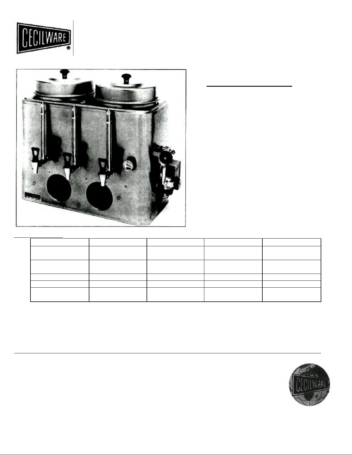
OPERATION MANUAL
COFFEE URNS
MPO-3
MPO-6
MPO-303
MPO-606
MPO-9912
ELECTRICAL DATA:
Model No. Watts Volts Phase Hz
MPO-9912 9KW
6.8KW
MPO-606 7KW
5.3KW
MPO-303 5KW 240V 1 or 3 50/60
MPO-6 3.8KW 208V 1 or 3 50/60
MPO-3 3KW
2.3KW
The Model MPO-9912 is a commercial manually operated um which consists of one or more thermostatically controlled heating element
assemblies housed, except for terminals, within the main water compartment. The bottoms of the two brewing containers extend down
into the main water compartment. The water level is maintained by a manually controlled water inlet valve.
Models MPO-606 and MPO-303 are identical in construction as Model MPO-9912, except for physical size and wattage.
Models MPO-6 and MPO-3 are similar in construction to the MPO-9912, except that they have only one brewing chamber and less
wattage.
240V
208V
240V
208V
240V
208V
1 or 3 50/60
1 or 3 50/60
1 or 3 50/60
Cecilware sells value... Worldwide.
NA56A 7/95
Page 2

" HOW TO MAKE GOOD COFFEE"
INSTRUCTIONS FOR THE OPERATION AND MAINTENANCE OF COFFEE URNS.
IMPORTANT: Do not turn the heating unit on until water has been placed in the water section of the um.
1. Install the coffee um in its proper place and connect a cold water line to the inlet valve. The inlet valve is mounted on the right side of the um.
2. Open the Inlet Valve by turning it in a counter clockwise direction. Fill the water section with desired amount of water.
3. Turn the heating unit to its high position to bring the water up to its brewing temperature. The dial thermometer will show the brew area.
4. When the dial thermometer registers "brew", the water in the water section is ready to be drawn for the brewing of coffee.
5. Place an um bag (freshly rinsed in cold water) into the griddles riser which rests on top of the um liner. Spread the proper quantity of coffee,
according to the formula being used so that it forms a level bed at the bottom of the riser. Then pour water (at brewing temperature) over the
coffee grounds, a gallon at a time, replacing the cover between each pouring. Remove the griddle riser from the um after the final pouring has
dripped through, to prevent the possible extraction of bitter substances. After the riser has been removed, mix the brewed coffee by drawing
off one gallon and pour it back into the um.
NOTE: The above instructions apply to single urns. In twin urns, the operation described above is the same, and can be used on either side alternately.
CLEANING;
It is essential that the coffee um be cleansed thoroughly at the end of each working day. The stainless steel liner should be thoroughly washed with a soft
brush, using hot water. One tablespoon of bicarbonate to each gallon of hot water is sufficient. There are many makes of urn cleaners on the market,
anyone of which can be used satisfactorily. Gauge glasses should be cleaned with a hard bristle brush. Faucets should be taken apart and cleaned
properly.
MAINTENANCE TIPS
FOR QUALIFIED SERVICE TECHNICIANS ONLY
CAUTION: Disconnect Power before any electrical repairs
Water Fails To Heat;
- Check line fuses.
- Pilot light should be ON when the thermostat is in the ON position. If the pilot light is ON, we can assume the thermostat is
operating properly; however, the wiring or heater may be at fault.
Replacing Heater:
1. Shut off electrical power and disconnect water supply.
2. Drain water from urn.
3. Remove right gauge glass and faucet.
4. Lift out liner from um body.
5. Tilt um and remove electrical connections to heater from underneath.
6. Remove socket head screw and heater flange and lift the heater out.
7. Install new heater and assemble other components in reverse order.
8. Repeat priming instructions.
Page 3

Thermostat:
1. Check line fuses.
2. Be sure thermostat is in the ON position. If pilot light fails to come on,, thermostat is most likely at fault.
3. Tilt um and check wiring underneath before removing the thermostat. If wiring seems to be in good condition, proceed as follows:
- Remove thermostat knob and remove two screws.
- Lift out thermostat and disconnect electrical wires to thermostat.
- Unscrew packing nut and pull out thermostat bulb from bottom of urn.
- Install new thermostat.
Thermostat Adjustment:
To adjust the temperature of the water in the um (206°F), turn the thermostat knob to its maximum clockwise position. Remove the knob by
pulling it toward you. A small adjusting screw will be visible in the center of the shaft. Insert a small screwdriver in the center of the shaft and observe the
temperature on the dial thermometer. When the indicator of the thermometer approaches the "W" in the word BREW, slowly rotate the screw clockwise
until the pilot light on the thermostat goes off. Turning the screw clockwise lowers the temperature and, conversely, turning counter-clockwise raises it.
Procedure for Lighting or Relighting:
1. Turn GAS COCK HANDLE to OFF position, and DIAL ASSEMBLY to lowest temperature position.
2. Wait sufficient length of time to allow gas which may have accumulated in burner compartment to escape.
3. Turn GAS COCK HANDLE to "Pilot" position.
4. Fully depress SET button, and light pilot burner. (Adjust, if necessary, as noted under "Pilot Burner Adjustment.")
5. Allow pilot to bum approximately '/2 minute before releasing SET button. If pilot does not remain ignited, repeat procedure allowing
longer period before releasing SET button.
6. Turn GAS COCK HANDLE to ON position and turn DIAL ASSEMBLY to desired position. The main burner will then ignite.
Pilot Burner Adjustment:
1. Remove pilot adjustment cap. Adjust pilot key, allowing flame to completely envelop the end 3/8" of the Thermocouple.
2. Adjust pilot burner air shutter (if provided) to obtain a soft blue flame.
Main Burner Adjustment (Gas Input):
1. To adjust main burner flame, turn screw under GAS COCK HANDLE in either direction to regulate flow of gas to main burner.
To Recalibrate Thermostat:
1. Allow heater to sit without the burner on for at least 30 minutes to allow the water temperature within the tank to reach its equilibrium
point.
2. Turn the DIAL ASSEMBLY until the main burner ignites.
3. Slowly turn the DIAL ASSEMBLY until the main burner is extinguished.
4. Place a Thermometer in the hot water flowing from the nearest faucet. If the DIAL ASSEMBLY setting is within 10° of the water
temperature, recalibration is not necessary. If the temperature variation exceeds 10°, proceed as follows to recalibrate:
- Remove DIAL ASSEMBLY GAS COCK HANDLE and ORNAMENTAL COVER, (to remove cover, unsnap at
base, lift out and up), and loosen (do not remove) screw.
- Hold STOP while screw is loosened, taking care not to move TEMPERATURE ADJUSTING SCREW.
- Hold TEMPERATURE ADJUSTING SCREW and turn STOP until water temperature setting coincides with that
of the thermometer.
- Hold TEMPERATURE ADJUSTING SCREW and STOP and tighten screw.
- Replace ORNAMENTAL COVER, GAS COCK HANDLE, and DIAL ASSEMBLY.
Page 4

Thermocouple connection:
Poor contact between the Thermocouple Lead and the Magnet Assembly may cause the Valve to be inoperative even when the pilot is
properly adjusted and positioned; if so, the contact points should be cleaned and tightened. This is accomplished by removing the
Thermocouple and carefully cleaning the parts that make contact with the Magnet Assembly.
CAUTION: When reassembling and tightening the Thermocouple Nut, only a small (3" or 4") wrench is necessary. Run nut down as far as
possible with the fingers. Set lock washer by making an additional 1/4 to 1/2 turn with the wrench.
PARTS LIST
ITEM STOCK NO.
3 GALLON SQUARE URNS
10 3/4" Gauge Glass only - Coffee X004A
10 3/4" Gauge Glass with Shield - Coffee D020A
Shank only D021A
FOR SHUTOFF SHANKS
9 1/2" Gauge Glass only - Water X005A
9 1/2" Gauge Glass with Shield - Water D001A
Shutoff Shank only D022A
5 and 6 GALLON URNS
15 1/2" Gauge Glass only - Coffee and Water X003A
15 1/2" Gauge Glass with Shield - Coffee and Water D018A
Shank only D021A
Shutoff Shank only D022A
Electric Thermostat D 1 L029T
Gas Thermostat L024A
Steam Thermostat 15-50 psi L003A
Angle Union Inlet Valve D006A
Central Self-Closing Inlet Valve D012A
Dial Thermometer "Brew" L007T
Cover Knob Complete M027T
UV Gas Valve F008A
Valve Seat for Angle Union Valve X023A
Washer Kit for Shields X012A
Gas Burner (for Single Urns only) G052A
Gas Burner (for Twin Urns only) G090A
Steam Thermostat 0-15 psi LOOOA
Water Compartment Vent Cover U019H
Budget Um Cover Complete Q023Q
# 10 Urn Bag V063A
# 12 Urn Bag V064A
# 14 Urn Bag V065A
8 3/4" Urn Ring V067A
10 1/2"Urn Ring V068A
 Loading...