

Page 1
OPERATION MANUAL
MODELS:
ME-10G
ME-15G
SPECIFICATIONS
INSTALLATION
MAINTENANCE TIPS
REPAIR PARTS LIST
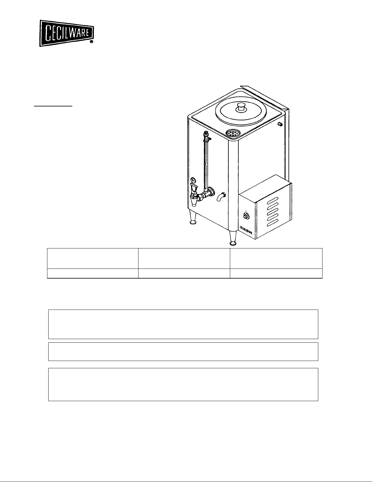
AUTOMATIC GAS
WATER BOILER
GAS SPECIFICATIONS
MODEL NO.
ME-10G, ME-15G 12,000 12,000
DO NOT STORE OR USE GASOLINE OR OTHER FLAMMABLE VAPORS AND
LIQUIDS IN THE VICINITY OF THIS OR ANY OTHER APPLIANCE.
THIS INSTALLATION MUST CONFORM WITH THE NATIONAL FUEL GAS CODE,
WARNING: IMPROPER INSTALLATION, ADJUSTMENT. ALTERATION, SERVICE
OR MAINTENANCE CAN CAUSE PROPERTY DAMAGE, INJURY OR DEATH. READ
THE INSTALLATION, OPERATING AND MAINTENANCE INSTRUCTIONS
THOROUGHLY BEFORE INSTALLING OR SERVICING THIS EQUIPMENT.
NATURAL GAS
BTU/HR @ 3.5" W.C.
FOR YOUR SAFETY
ANSI Z223.1 (LATEST EDITION).
PROPANE GAS
BTU/HR @ 10" W.C.
CECILWARE CORPORATION
43-05 20TH AVENUE, LONG ISLAND CITY, NY 11105-1295
• 718932-1414
N795A 08/99 DS
Page 2

SAFETY PRECAUTIONS
FOR YOUR SAFETY, THE FOLLOW SAFETY PRECAUTIONS SHOULD
BE FOLLOWED AND ENFORCED.
IF YOU SMELL GAS:
• OPEN WINDOWS
• DON'T TOUCH ELECTRICAL SWITCHES
• EXTINGUISH OPEN FLAMES
• IMMEDIATELY CALL YOUR GAS SUPPLIER
1. Instructions must be posted in a prominent location and all safety precautions taken
in the event the user smells gas. Obtain this information from your local gas supplier.
2. LIGHTING: Follow the instruction on page 6 and label attached to right side of water
boiler.
3. Do not place anything over the flue opening.
4. Do not place combustibles or non-combustible materials in the
proximity of water boiler as this could cause fires or obstruct air flow to the main
burners.
5. This installation must conform with local codes, or in absence of local codes with the
National Fuel Gas Code ANSI Z223.1, latest edition.
6. Provide adequate air supply and ventilation.
7. Provide adequate clearance for air openings into the combustion chamber.
8. Provide clearance for servicing and proper operation. Minimum clearance from
combustible construction 8" from back and 6" from side.
9. Boiler must be disconnected from gas supply during any pressure testing of
pipelines in excess of 1/2 psig, and isolated (by turning off gas shut-off valve) during
any testing less than 1/2 psig.
10. Retain this manual for future reference.
UNPACKING INSTRUCTION: Carefully unpack the water boiler and inspect
immediately for shipping damages. Your automatic water boiler was shipped in a carton
designed to give maximum protection in normal handling. It was thoroughly inspected
before leaving the factory and the carrier accepted and signed for it. File any claims for
shipping damage or irregularities with the carrier.
ASSEMBLY: The four legs, faucet, float ball, and vent cap drain are packed separately
with the water boiler. Install legs by tilting the water boiler on its side and screwing the
legs into the leg supports until hand tight. Carefully right the unit and install it in its
permanent location, being sure to leave at least 6" on the right side of the water boiler
for access to the control box. Level the unit by adjusting the bottom pad of the legs.
Screw the ball float (54 on Parts III.) onto the end of the water
2
Page 3
inlet valve rod (53). Place the vent cap (50) into the recess in the top of the unit. Mount
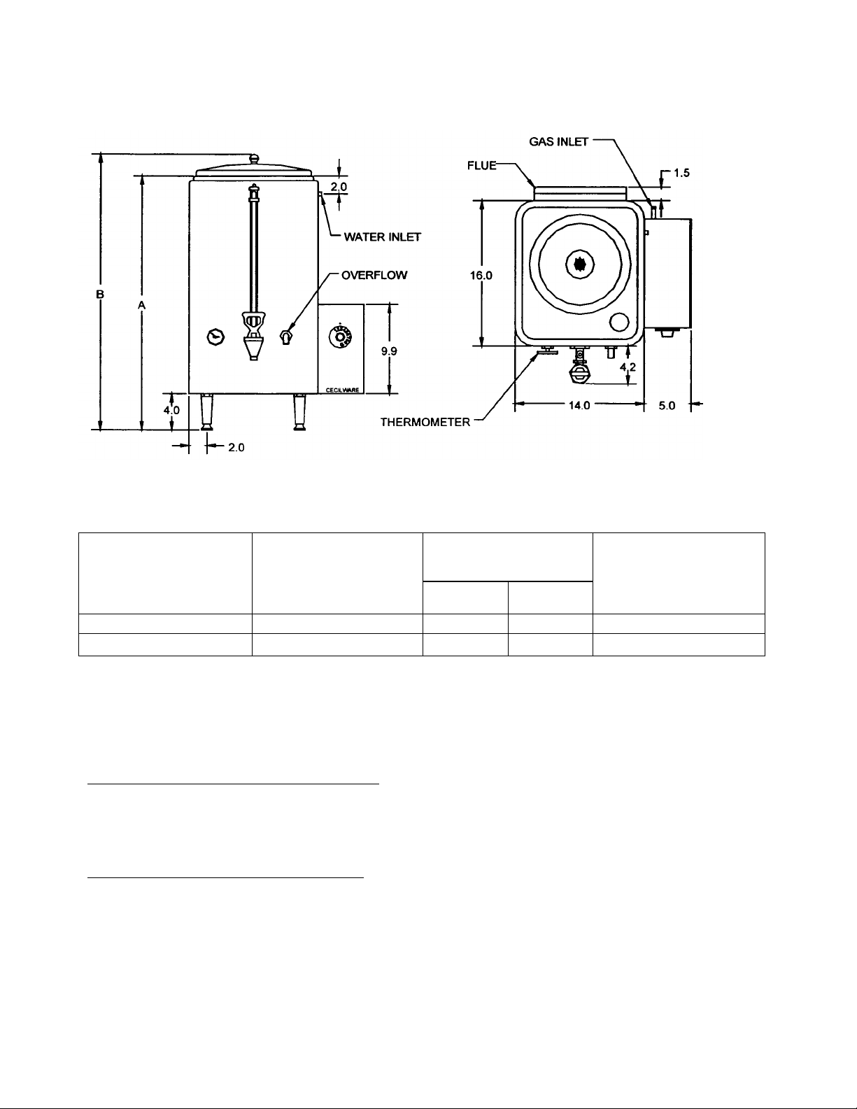
ME-10G
10.0
28 31
50.0
the faucet assembly (56) onto the shank (18).
10 AND 15 GALLON GAS WATER BOILERS
Water
Model no.
ME-15G 15.0 32 35 55.0
Capacity
(Gallons)
Dimensions
(inch)
A B
Shipping Wt.
(Ib.)
INSTALLATION AND OPERATING INSTRUCTION:
PRE-INSTALLATION INSTRUCTIONS: The installation of your water boiler must be
made by a licensed plumber and the installation must conform with State and Local
Codes or in absence of Local Codes, with the National Fuel Gas Code ANSI Z223.1 a
latest version.
AIR SUPPLY AND VENTILATION: Adequate ventilation and air supply must be
provided in order for the water boiler to operate properly and efficiently. The area in
front of and above the unit must be clear to avoid any obstruction of flow of combustion
and ventilation air. DO NOT under
any circumstances, connect the water boiler flue directly to 3 building exhaust system
or place the flue outlet directly into the plenum of the exhaust hood as it will adversely
affect the gas combustion of the water boiler.
3
Page 4

ME-10/15G
AUTOMATIC
WATER BOILER
PARTS ILLUSTRATION
4
Page 5

PARTS LIST ME-10/15G
NO DESCRIPTION ME-10G ME-15G
1 KNOB M027A M027A
2 COVER Q102H Q102H
3 BODY R477A R478A
4 GAUGE SHIELD MTG BRACKET U160A U160A
5 VENT CAP ASSEMBLY X046A X046A
6 GAUGE SHIELD WASHER KIT X012A X012A
7 WATER GAUGE GLASS X043A X073A
8 WATER GAUGE SHIELD D031A D066A
9 DIAL THERMOMETER L007A L007A
10 CHROME PLATED NUT 3/8" NPT K110A K110A
11 OVERFLOW TUBE H081A H080A
12 HANDLE X007A X007A
13 BONNET X010A X010A
14 FAUCET SPRING SS X019A X019A
15 STEM X058A X058A
16 CUP SEAT X014A X014A
17 FAUCET X149A X149A
18 SHANK D021A D021A
19 OVERFLOW DRAIN E009A E009A
20 BURNER SUPPORT BRACKET R483A R483A
21 LEGS SET OF 4 M005A M005A
22 T-BURNER G052A G052A
23 PILOT SUPPORT BRACKET U670A U670A
24 PILOT ASSEMBLY, NAT F135A F135A
PILOT ASSEMBLY, LP F134A F134A
25 ORIFICE, NAT F160A F160A
ORIFICE, LP F161A F161A
26 WASHER SS P813A P813A
27 REDUCING COUPLING 1/4 X 3/8 " J041A J041A
28 ORIFICE BRACKET U674A U674A
29 SIDE BOX RZ16A RZ16A
30 SLIDE UB12A UB12A
31 THERMOSTAT L622A L622A
32 THERMOPILE F178A F178A
33 WIRING HARNESS CH32A CH32A
34 3/8 STREET ELBOW, BLACK STEEL J040A J040A
35 1/4 COMPRESSION FITTING K039A K039A
36 1/4 PI LOT TUBE, ALUM H345A H345A
37 BLACK NIPPLE, 3/8 NPT X 4" J015A J015A
38 GAS VALVE L621A L621A
39 ELBOW COMP FTG, BRASS 3/8 X 3/8 NPT K635A K635A
40 3/8 GAS VALVE TUBE H346A H346A
41 SCREW, 8-32 X 3/8 P013A P013A
42 GAS VALVE BRACKET UB11A UB11A
43 SIDE BOX DOOR RZ17A RZ17A
44 SIDE BOX BACK RZ18A RZ18A
45 STAR WASHER, #10 P072A P072A
46 HEX NUT, 8-32 P010A P010A
47 WELD STUD, 8-32 X 3/4 P125A P125A
48 HEX BUSHING 3/4 X 3/8 K636A K636A
49 FLUE R481A R481A
50 VENT CAP U019A U019A
51 SILICONE GASKET M256A M256A
52 STEM VALVE M0251 M0251
53 ADAPTER 1/4-20 M0589 M0589
54 FLOAT, SS 3” M0892 M0892
LP CONVERSION KIT L347P L347P
55 WATER GAUGE ASSEMBLY D020A
56 FAUCET ASSEMBLY D017A D017A
5
Page 6

CLEARANCES: Your water boiler is design certified to use on combustible floors. The
side and back clearances for combustible constructions are as follows: 6 inches from
side and 8 inches from back. The water boiler must be installed with 4 inch high legs
provided.
GAS CONNECTION: Before connecting the water boiler to the gas line, check the
rating label on the side panel to make sure that the gas type called for on the label
coincides with the type of gas available on site. A 3/8 NPT gas connection is needed
to connect the unit to the gas line. An accessible manual shut-off valve must be
installed in the gas supply line in case of an emergency. The gas supply pipe must be
sized to accommodate all the gas fired equipment that may be connected to it. Check
with your local Gas Company as to proper pipe size. Sealant on all pipe joints must
be resistive to propane gas. Before attempting to light the water boiler, check all joints
for gas tightness using a soap and water solution.
WATER CONNECTION: Use 1/4 inch outside diameter copper tubing to
connect the unit to the water supply line. The water line must have a
shut-off valve (supplied by a plumber). At the unit, connect the tubing to
the compression water inlet valve at the upper right hand side of the
unit.
NOTE: Connecting the unit to a warm water supply will speed by heating
and recovery time.
PRIMING OR INITIAL FILLING: Turn on the water supply. The unit fills at the rate of 1
gallon/minute. When the water level becomes visible in the side gauge turn the
thermostat knob to ON position. The boiler will now automatically fill to capacity and
heat the water.
LIGHTING AND ADJUSTMENT: Water must be visible in the sight glass before
lighting to pilot. Turn the thermostat knob to its lowest position. Turn gas cock dial to
PILOT position. Depress gas cock dial and light pilot with a long lighted match
through the opening located to the right of the thermostat. Hold in depressed position
for approximately 30 sec. or until pilot remains lit when dial is released.
NOTE: On the first lighting it may be necessary to hold the dial for a longer period to
allow trapped air to escape from the line.
DIAL SETTINGS AND CORRESPONDING WATER TEMPERATURES:
"1"= 50F,"10”=198F
6
Page 7

RELIGHTING: Shut off all gas and wait approximately 3 minutes before relighting the
pilot.
SHUTTING DOWN: For temporary shut down, turn the thermostat to lowest or OFF
position; then turn gas cock dial to PILOT position. To shut boiler down completely,
partially depress and turn gas cock dial to OFF position.
MAINTENACE OR REPAIR: The owner should contact either the manufacturer or an
approved local service company for maintenance or repair of the unit.
CLEANING: The outside of the unit should be cleaned on a regular basis using a
soap solution and a soft cloth or sponge. Abrasive cleaners are not recommended.
For cleaning the burner see section on removal and" cleaning.
FOR QUALIFIED SERVICE PERSONNEL ONLY
THERMOSTAT CALIBRATION: Turn the thermostat knob to "10" and remove knob
without moving the thermostat shaft. Place narrow bladed screw driver (1/8") into the
hollow thermostat shaft and engage center adjustment screw. When thermometer
reading approaches 198F slowly turn the adjustment screw clockwise until the burner
goes out. Turning the screw counter-clockwise will increase the temperature.
SAFETY PILOT: Remove pilot adjustment cap on the gas valve and turn adjustment
screw to provide properly sized flame (3/4 inch long). Replace the cap.
BURNER: Burners are factory set for maximum performance. Should further
adjustment be required loosen slotted hex screw on side of venturi and rotate air
shutter until flame with soft blue inner cone is obtained.
7
Page 8

BURNER REMOVAL: The burner can be removed with the unit standing in operating
position. Turn off the gas flow to the unit. Allow the burner to cool off. Remove the wing
nut holding the burner to the frame. Pull down the free burner end, enough to clear the
threaded stud and pull the burner horizontally away from the manifold orifice. The
burner can now be cleaned or replaced. To reinstall reverse the above procedure.
BURNER MAINTENANCE: The burner should be cleaned both inside the venturi
portion and on the outside using a soft bristle brush. The burner must be replaced into
the same position as prior to removal. Once a year a qualified service agency should
be contacted to inspect the appliance for safe and proper operation.
8
 Loading...