

Page 1
JAVA2-LP MANUAL
Cecilware sells value...
Worldwide
43-05 20th Avenue, Long Island City, 11105 718-932-1414
Fax: 718-932-7860
OPERATIONAL MANUAL
• Specifications...........................……………..
• Installation & Start Up
Procedure……………
• Programming...............................…………...
• Adjustments................................…………...
• Cleaning & Sanitizing...............………………
• Parts Identification..................………………
• Wiring Diagrams.....................………………..
LECTRICAL SPECIFICATIONS:
120 Volts
15 Amp Circuit
60 Hz
1 Heater
1,700 Watts
5-15R Receptacle
MECHANICAL SPECIFICATIONS:
Width: 8.5"
Depth: 20"+2" Clearance For Waterline.
Height: 21"+2.5" Legs.
Cup Clearance: 4.5"
Hopper Capacity: 1 Lb Dry Coffee.
Tank Capacity: 1 Us Gal.
Burst Rate: 120 Cups/Hr.
Recovery Time: 5 Min.
FACTORY SETTINGS:
Gram Throw Dial: 2.4
Coffee Gram Throw: 2.2 gr. Coffee /8 oz. Cup.
Water Flow Rate: 1 to 1.3 oz./sec.
1
2
3
3
5
10
11
Page 2

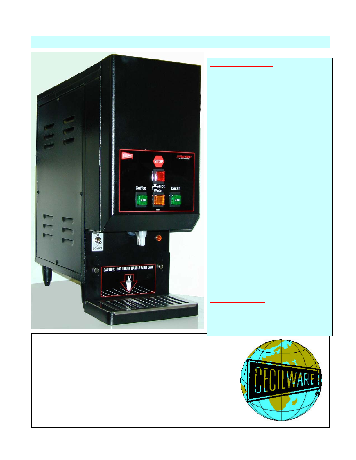
INSTALLATION
Water Inlet Connection:
This equipment is to be installed to comply with the applicable Federal, State, or local plumbing codes having jurisdiction. In
addition:
1. A quick disconnect water connection or enough ext
ra coiled tubing (at least 2x the depth of the unit) so that the machine
can be moved for cleaning underneath.
2. An approved back flow prevention device, such as a double check
valve to be installed between the machine and the water
supply.
The JAVA2-LP is equipped with a 1/4"
Flare Water Inlet Fitting, located on the lower left side in the back of the base.
HIGHLY RECOMMENDED:
A WATER SHUT-OFF VALVE and A WATER FILTER, pref
erably a combination Charcoal/Phosphate Filter, to remove odors and
inhibit lime and scale build up in the machine. Note: In areas with extremely hard water, a water softener must be installed
in order to prevent a malfunctioning of the equipment and in order not to void the warranty.
STARTUP PROCEDURE
Caution: Make sure that the Heater Switch, located behind right hopper with door opened,
1. Connect the 1/4" dia copper waterline to the 1/4" flare water inlet fitting of the valve.
2. Plug the power cord i
nto a proper receptacle.
3. Activate the Power Switch (Toggle Up). T
he door display panel and the green dispense buttons will light up and the tank
will start filling. Allow approximately 2 minutes for the tank to fill.
4. Activate the Heater Switch. Allow approximately 15 - 20 minutes for
the water to reach a preset temperature of
200°F. The heat up time will depend on the water inlet temperature, the input voltage and the wattage of the elements
in the machine.
5. Place cup under nozzle and press dispense switch. The machine will dispense wat
Repeat it several times for each dispen
se switch to check for consistent output.
er at the rate of 1-1.3 oz. per second.
6. While the tank is heating up, remove the hoppers, load them with products and reposition them back in the machine.
When the heater light goes OFF, t
he tank has reached its brew temperature and the machine is ready to dispense Coffee.
VOLUME AND DRINK SIZE ADJUSTMENTS:
2
is in the OFF position.
Page 3
PROGRAMMING INSTRUCTIONS FOR AUTOMATIC DISPENSE
1. Turn Power Switch ON (toggle switch inside door).
2. PRESS and HOLD [red] STOP Button with one hand.
3. PRESS and HOLD [green] DISPENSE Button with other hand.
4. RELEASE [red] STOP Button ONLY.
5. Continue to HOLD [green] DISPENSE Button for 5 SECONDS, then RELEASE.
6. PRESS and RELEASE [green] DISPENSE Button. Product begins dispensing.
When it reaches the "DESIRED VOLUME",
7. PRESS and RELEASE [green] DISPENSE Button to SET "DESIRED VOLUME".
DISPENSE Button can be "jogged" to top off.
8. PRESS and RELEASE [red] STOP button to LOCK IN "DESIRED VOLUME".
Repeat steps 1 to 8 for each Dispense Button.
PROGRAMMING INSTRUCTIONS FOR MANUAL DISPENSE
1. PRESS AND HOLD STOP [red] BUTTON WITH ONE HAND.
2. PRESS AND HOLD DISPENSE [green] BUTTON WITH OTHER HAND.
3. RELEASE STOP [red] BUTTON.
4. RELEASE DISPENSE [green] BUTTON.
5. PRESS AND RELEASE STOP [red] BUTTON.
The Total Time The Water Is Running Is Accumulated And Saved Into Memory. For Normal Operation,
Press and Release Dispense Button.
The Automatic Dispense Buttons are factory programmed to dispense 8 oz. of Water per cup.
PRODUCT STRENGTH ADJUSTMENTS:
The JAVA units have variable speed control auger motors [CD151 with variable
speed of 10 to 130 RPM].
Drink or Product Strength can be changed by adjusting the Gram Throw Dial on inside door panel.
The Gram Throw is factory preset at approx. 2.4 (2.2 gr. per 8 oz. cup) for the JAVA2-LP machines.
The water flow rate adjustment for the dispense valve should remain fixed bet. 1 - 1.3.
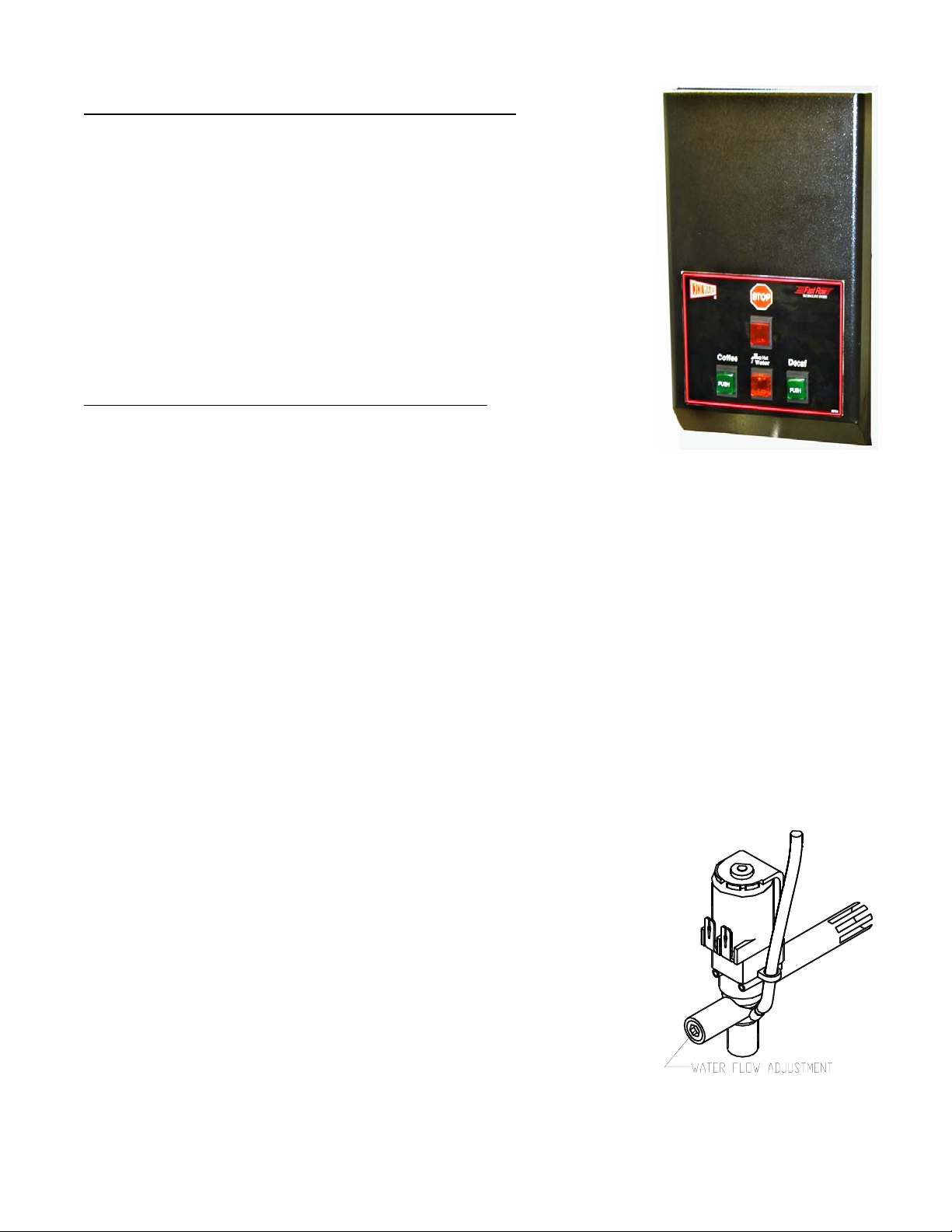
HOT WATER FLOW RATE ADJUSTMENTS:
Note: Remove right side panel to access the Water Dispense Valves, .
TO ADJUST HOT WATER FLOW RATE:
1. Remove right side panel to access the Water Dispense Valves, mounted on tank.
2. Locate adjustment screw on Dispense Valve.
3. Using Allen Key or flat screwdriver rotate, 1/4 turn at a time,
CLOCKWISE to decrease water flow, or COUNTERCLOCKWISE to increase water flow.
4. Check water flow output, after each 1/4 turn.
3
Page 4
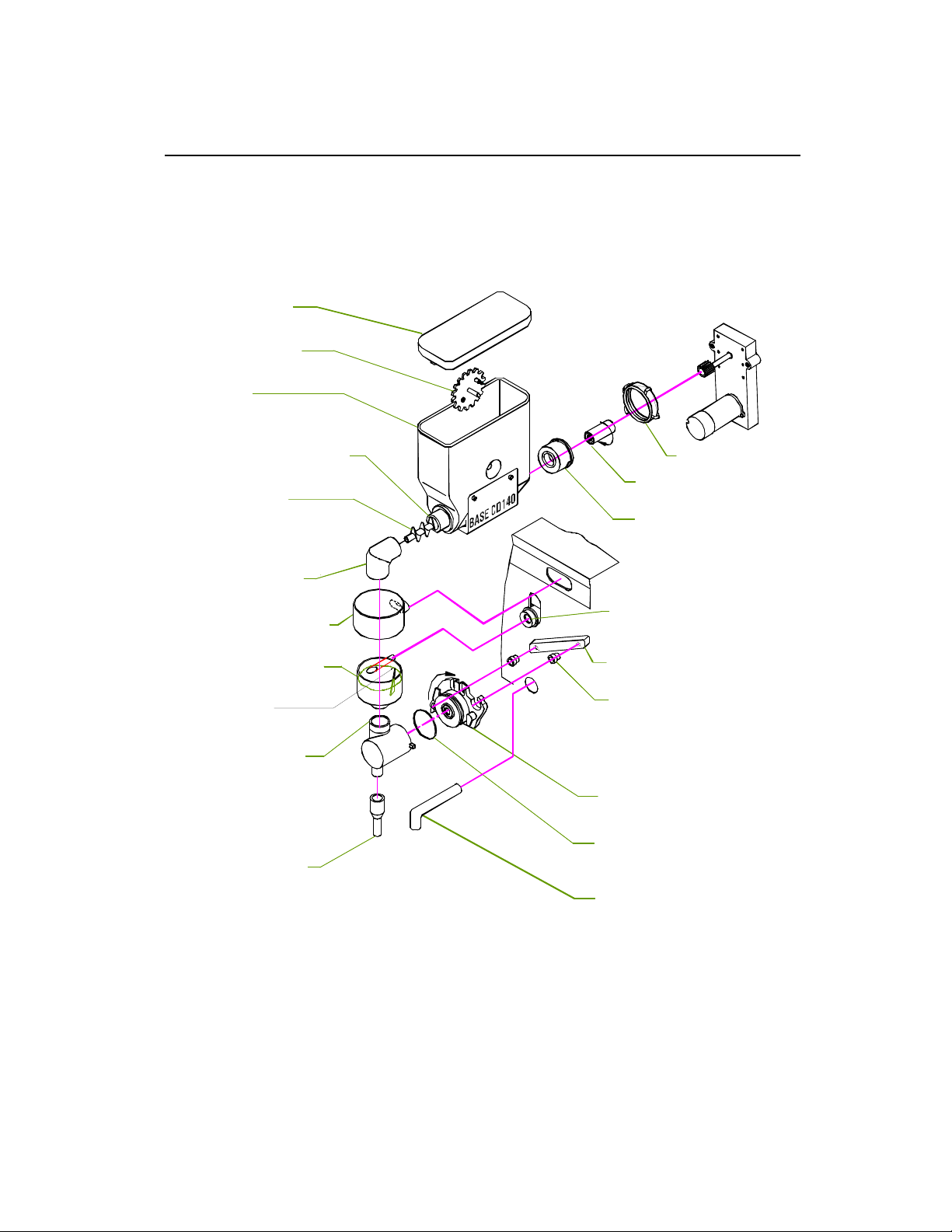
JAVA2-LP HOPPER ASS'Y CD313 & DISPENSE ASS'Y
CAPACITY- 1 LB COFFEE, 7.875"H w/cover x 3"W, W/NYLON AUGER
HOPPER COVER CD106
AGITATOR GEAR CD117
HOPPER CD313
AUGER BUSHING FRONT CD277
NYLON AUGER CD130
(22.5Øx18mmPT)
W/"O" RING CD139
PRODUCT GUIDE CD70A
DISPENSE CAP BLK - CD272
MIXING CHAM. BLK - CD275
8 mm dia. opening
NOTE WATER LEVEL
DC MOTOR CD151 90rpm
(Portion Control)
NUT [2] CD278
FLANGE/NUT CD136
AUGER BUSHING
BACK CD279
MIX BOWL SOCKET CD67A
W/O-RING M378A
BASE MOUNT BAR CD89A
BASE MOUNT GROMMET CD66A
WHIP CHAM. BLK-CD321
MOUNTING BASE BLK - CD322
EXTENSION TUBE M849A
M379A 'O'-RING #125
EXTENSION TUBE K682A
4
Page 5

CLEANING AND SANITIZING:
SANITIZING: All food dispensing units should be sanitized periodically. All parts to be sanitized must be cleaned first.
To prepare a sanitizing solution: ADD 2 TSP. OF LIQUID CLOROX BLEACH (5.25% CONCENTRATION) TO 1 GALLON OF
WATER AT ROOM TEMPERATURE (70° - 90°F).
Soak all parts for a minimum of 3 min. in the sanitizing solution. Note: Always start with a unopened bottle of Clorox Bleach
since the solution from an opened bottle has a short life span.
Let all sanitized parts drain and dry naturally. DO NOT WIPE THEM DRY. Before using the sanitized unit (or parts) with food
stuffs, rinse all parts thoroughly with water.
CARE FOR STAINLESS STEEL:
Stainless Steel surfaces that come in contact with food
substances, MUST BE CLEANED EVERY DAY.
WHEN CLEANING STAINLESS STEEL , ONLY A pH
NEUTRAL CLEANER IS TO BE USED.
Use nylon or brass brushes (not steel wire brushes) for
HOPPER
ASS’Y
removing food deposit.
Many food products contain acids,alkalies, or other
substances which corrode Stainless Steel.
RECOMMENDED DAILY CLEANING AND MAINTENANCE
1. Empty drip tray and wash with dish detergent.
2. Rinse Chamber:
PRODUCT
GUIDE
3. Flip RINSE SWITCH ON and press DISPENSE BUTTON.
4. Flip RINSE SWITCH OFF. Remove and refill Hopper.
5. Turn PRODUCT GUIDE UP to reduce spillage.
DISPENSE
CAP
CLEAN HOPPER (once a week)
a. Open cabinet door and top lid.
b. Turn the product guide up, to reduce spillage.
c. Empty out Hopper.
DISPENSE
CHAMBER
d. Pull off Product Guide.
e. Unscrew Agitator and remove.
f. Remove the auger by turning the hopper
horizontal, auger will fall out.
g. Wash parts with dish detergent.
MOUNTING
BASE
WHIPPER
CHAMBER
h. Rinse, dry, and re-assenble parts.
CLEAN DISPENSE CHAMBER (once a week)
1. Twist CW and pull off STEAM DEFLECTOR.
2. Pull off DISPENSE CHAMBER.
PRODUCT
NOZZLE
6. Wash components with dish detergent.
7. Rinse, dry, and re-assenble parts.
5
Page 6

FRONT OPEN VIEW
1
2
3
4
5
6
7
8
9
10
11
12
13
14
15
16
23 24
22
20
19
18
17
25
26
27
28
21
6
Page 7

RIGHT SIDE OPEN VIEW
2 1 3
7
Page 8

LEFT SIDE OPEN VIEW
3 2 1
12
11
10
9
8
7
6
5
4
8
Page 9

TANK TOP ASS’Y
2
3 1
4
5 6 7 8 9
9
Page 10

FRONT OPEN VIEW
ITEM P/N QTY DESCRIPTION
1 RX67A 1 TOP COVER, CABINET
2 SF79A 2 SIDE PANELS
3 CD313 1 HOPPER ASS'Y
4 M705A 1 DOOR LATCH
5 RV57Q 1 TROUGHT DRAWER ASS'Y
6 CD272 1 STEAM DEFLECTOR
7 CD67A 1 SOCKET F/ MIXING BOWL
8 L299A 1 RINSE SWITCH
9 CD275 1 DISPENSE CHAMBER [8mm dia.]
10 CD321 1 WHIPPER CHAMBER
CD322
M848A
11
CD66A
CD89A
12 L069A 1 POWER SWITCH
M849A
13
K682A 1 1
14 NA91A 1 CAUTION LABEL
15 SF84A 1 GRILL
16 SF83A 1 TRAY
17 SF23A 1 FACIA BOTTOM CAP
18 C002A 1 HEATER LIGHT
19 CH93A 1 DOOR HARNESS
20 K618A 1 HIDDEN HINGES [1 SET]
NF17A
21
NF58A
N978A
22 SF19Q 1 DOOR FRAME ASS'Y
SF21A
SF22A
23
L576A
L557A
24 L567A 1 HEATER SWITCH
25 Ni70A 1 SWITCH PANEL LABEL
26 L574A 1 STOP SWITCH RED
27 L457A 1 HOT WATER SWITCH AMBER
28 L455A 2 DISPENSE SWITCH GREEN
1
BASE MOUNT CLOSED
PLUG F/ BASE MOUNT
1
GROMMETS
2
MOUNTING BAR
1
COFFEE SPOUT, WHITE TEFLON 1.75” L
HOT WATER SPOUT [1.5”L X 4”L]
1
START UP PROCEDURE INSIDE DOOR
1
PROGRAMMING INSTRUCTIONS
1
CLEANING AND SANITIZING INSTRUCTIONS
1
INSIDE DOOR PANEL
1
KNOBS COVER
3
TEACH ME TIMERS
2
POTENTIOMETERS
F/ WHIP. CHAMBER
RIGHT SIDE OPEN VIEW
ITEM P/N QTY DESCRIPTION
1 L556A 2 SPEED CONTROL BOARD F/AUGER MOTOR
2 CD151 2 AUGER MOTOR
3 CD56A 1 BLOWER
LEFT SIDE OPEN VIEW
ITEM P/N QTY DESCRIPTION
1 L566A 1 LEVEL CONTROL BOARD
2 B129A 2 RELAYS, SAFETY
3 CF29A 2 TRANSFORMERS
4 CD257 1 WATER INLET VALVE
5 M830A 1 HOSE - inlet valve to tank .375 Id x 9"L
6 M829A 1 HOSE - drain .375 IDx12"L
7 K525A 1 ELBOW
8 M832A 1 HOSE - Disp. Valve, Nozzle .375 Id x 11"L
9 M831A 1 HOSE - Disp. Valve–Chamber .375 Id x3.5"L
10 L467A 2 DISPENSE VALVE [1-Product, 1-Hot Water]
11 M494A
M461A 1 6
12 SG06Q
M600A 1 1
GROMMET PLUG [ F/ TESTING ]
GROMMET [ 0.466 DIA ]
TANK BODY ASS’Y
SPLICED GASKET,
CUT FROM 21.75” TO 21”
10
Page 11

ITEM P/N QTY DESCRIPTION
1 L573A 1 HI-LIMIT, SURFACE MOUNT
2 P465A 2 SCREW, TANK TOP 1/4-20x5/8
3 M461A 6 GROMMET [.446 ID]
4 L681A 1 THERMOSTAT
5 K402Q 1 LEVEL CONTROL PROBE
6 K525A
M787A 6
7 M 1 HOSE, BREATHER TUBE
8 G296A
03051
07059
M730A
9 L499A 1 FLOAT SWICH
TANK TOP ASS’Y SG08A
ELBOW TUBE, SS OR
ELBOW SILICON TUBE, BREATHER
1
HEATER 120V, 1500W
2
NUT F/ HEATER
2
WASHER F/ HEATER OUTSIDE
2
WASHER F/ HEATER INSIDE
11
Page 12

N
TEACH-ME
TIMER
2
314
TEACH-ME
TIMER
1
423
TEACH-ME
TIMER
231
4
L1
STOP
COFFEE DECAFF
HOT WATER
..
SPEED
CONTROL
D.C.
AUGER
MOTOR
COFFEE &
DECAFF
DISPENSE VALVE
WATER LEVEL PROBE - IN TANK
.
WATER INLET VALVE
FLOAT SWITCH
1 PROBE
3 N
2 L1
1 LOAD
HOT WATER
DISPENSE
VALVE
LEVEL
CONTROL
SPEED
CONTROL
DOOR UNIT
D.C.
AUGER
MOTOR
MAIN UNIT
FAN/BLOWER
HEATER LIGHT
N
.
THERMOSTAT
.
HEATER SWITCH
5-15P
5-15R
15A-1.7KW
POWER
SWITCH
L1
.
.
HI-LIMIT
CG 1 : 1
12
 Loading...