

Page 1
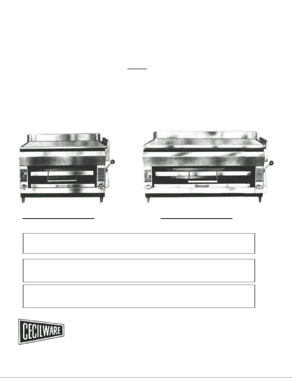
HEAVY DUTY GAS
BROILER-GRIDDLES
Contents
Specifications
Installation
Adjustments
Operating Instructions
Maintenance Tips Parts List
Drawings
MODEL HDB-2031 (Counter) MODEL HDB-2042 (Counter)
FOR YOUR SAFETY
DO NOT store or use gasoline or other flammable vapors and liquids in the vicinity of this or any other
appliance.
This installation must conform with local codes, with the National Fuel Gas Code. ANSI Z22.1 (latest
edition), National Gas Installation Code, CAN/CGA - B 149.1. or the Propane Installation Code.
CAN/CGA - B 149.2 as applicable.
WARNING: Improper installation, adjustment, alteration, service or maintenance can cause property
damage, injury or death. Read the installation, operating and maintenance instructions thoroughly before
installing or servicing this equipment.
CECILWARE CORPORATION
43-05 20th Avenue, Long Island City, N.Y. 11105 • 718-932-1414
N530A
Page 2

FOR YOUR SAFETY
DO NOT STORE OR USE GASOLINE OR OTHER
FLAMMABLE VAPORS AND LIQUIDS IN THE
VICINITY OF THIS OR ANY OTHER APPLIANCE.
SAFETY PRECAUTIONS
FOR YOUR SAFETY, THE FOLLOWING SAFETY PRECAUTIONS SHOULD BE FOLLOWED AND
ENFORCED.
1. Instruction must be posted in a prominent location and all safety precautions taken in the event the user
smells gas. Obtain this information from your local gas supplier.
IF YOU SMELL GAS:
1. OPEN WINDOWS
2. DON'T TOUCH ELECTRICAL SWITCHES.
3. EXTINGUISH ANY OPEN FLAMES.
4. IMMEDIATELY CALL YOUR GAS SUPPLIER.
2. Lighting - Follow the instructions on the label attached to the front of the griddle, or see page (2).
3. Do not place combustible or non-combustible materials in the vicinity of the griddle in order to prevent fires
and not obstruct air to the main burners.
4. Do not place anything over the flue opening.
5. This installation must conform with local codes, or in the absence of local codes, with the National Fuel
Gas Code, ANSI Z22.1 (latest edition), or National Gas Installation Code, CAN/CGA-B149.1. or the
Propane Installation Code, CAN/CGA-B149.2 as applicable.
6. Broiler, Griddle must be disconnected from gas supply during any pressure testing of piping system in
excess of 1/2 psig (3.45 K/pa) and isolated from gas supply piping system (by closing its individual
manual shut-off valve) during any pressure testing of piping system in excess of 1/2 psig.
7. Provide adequate air supply and ventilation.
8. Provide adequate clearance for air openings into combustion chamber.
9. Provide clearances for servicing and proper operation.
10. For use in non-combustible locations only.
Minimum clearances for non-combustible construction:
Rear: 6 inches; Sides: 8 inches
11. Retain this manual for future reference.
2
Page 3

BROILER— GRIDDLE/CHEESEMELTERS
Width:
31" Width:
42"
HDB-2031 HDB-2042
Gas Rate NAT 2 @ 30.000 BTU/Hr Gas Rate NAT 2 @ 45.000 BTU/Hr
PROP 2 @ 30.000 BTU/Hr PROP 2 @ 40.000 BTU/Hr
Dimensions
Griddle Area: 29"x19 ½” Griddle Area: 40"x19 ½”
Working Height:
Overall Height:
Depth:
UNPACKING
Carefully remove unit from container and inspect for any damage due to shipping.
Caution:
Examine the gas specification label attached to the front of the unit to be sure that the type of gas for which the unit is equipped is the same as the
gas supply available.
ASSEMBLY OF COMPONENTS
21"
25"
22"
INSTALLATION AND OPERATING INSTRUCTIONS
Dimensions
Working Height:
Overall Height:
Depth:
21"
25"
22"
Legs are shipped with unit in a plastic bag. To install the legs, tilt back and screw in the two front legs. Mount the rear legs by tilting unit forward.
Place baffle plates on frame and position over locating studs as illustrated in exploded view.
Griddle plate will be properly located when adjusting screws fall into the recesses provided in the plate. Turn adjusting screws (8) so that the left
hand side of the griddle plate is slightly higher than the right hand side which will enable the excess grease to drain off toward the grease can. A
minimum space of a least 5/8" between the griddle plate and the frame should be maintained to insure proper operation of the broiler-griddle.
Place grease can in groove provided for directly under grease trough in griddle plate.
Place food rack in lift rack runners and insert stop pins (30) in holes located in runners.
INSTALLATION NOTE: THIS INSTALLATION MUST CONFORM WITH THE NATIONAL FUEL GAS CODE, ANSI Z223.1 latest
Unit should be used in a non-combustible location.
NOTE: Use a pipe compound on all threaded joints resistant to propane gas.
CAUTION
Before connecting to gas supply line, check specification label for correct gas. A 3/4" gas connection is provided at the rear of the unit. A manual
shut-off valve should be installed between the gas supply line and the broiler. Check for gas leaks with soap solution before lighting.
LIGHTING AND ADJUSTMENTS
Before turning on main gas supply, burner valves should be in the "OFF" (horizontal) position. Turn on gas supply and light the two standing pilots
(9) visible from inside the broiling section as shown in the drawing on page (6). Length of pilot flame should be approximately ½” long for proper
ignition of burner.
edition.
3
Page 4

Two holes in front frame are provided through which the pilot flames may be adjusted by turning the screw
(10)
in the pilot valve as
indicated in drawing on page (6). Burner valve may now be turned to the "ON" position and burners should ignite. Proper flame
adjustment of burners is obtained by opening or closing of primary air shutters just below where yellow tipping of flames disappear.
An access door for each burner is located at the lower front of each inside panel (see drawing). Once the door is swung up the
burner can be adjusted by loosening the screw at the bottom of the burner venturi and rotating the primary air shutter until the
yellow tips of the flame disappear. Retighten the screw and close the access door.
SHUT DOWN - FOR COMPLETE SHUTDOWN, TURN MAIN GAS VALVE TO "OFF".
NOTE: These instructions are for initial lighting only. For normal operation of unit, following lighting instructions on front panel.
OPERATION
Turn burner valves to "ON" position and wait approximately 20 minutes for griddle to reach operating temperature. Food may be placed on
griddle or broiler rack and rack adjusted to desired position by lifting handle on right side of unit. For Stand-By periods and adjustment of
griddle temperature, turn valve handles between the "ON" and "OFF" positions.
MAINTENANCE
Very little maintenance is required on this unit. Air shutters should be cleaned of lint and dirt periodically. After longer periods, burners
and pilots should be cleaned for proper ignition and burner flame efficiency. If sticky valves become a problem, they should be
disassembled and lubricated with the proper lubricant by a qualified serviceman.
PREPARING GRIDDLE
The griddle surface is protected with a petroleum jelly. To remove this coating, light the burners and wait approximately 5 minutes
for the griddle to heat up, wet the entire griddle surface with clear water and add some griddle cleaner to the water. Let the cleaner
work a few minutes, then wipe the cooking surface dry. Apply a light cooking oil or shortening on the griddle plate.
Your griddle is now ready for normal operation.
A grease trough is provided at the right of the griddle with a drain chute which empties into a grease can. Loosen the soil on the
griddle plate and sweep it into the chute. Do not tap the edge of the spatula on the griddle plate, as this will mar the finish of the
polished surface and perhaps cause the food to stick when cooking.
CLEANING
Keep the griddle clean by washing and using griddle cleaners available from your dealer. Do not attempt to use any steel wool or
abrasives which will imbed in the plate. If these simple instructions are followed, your griddle will give you years of service.
Air shutters should be cleaned of lint and dirt periodically.
Contact a factory representative or a local service company if major repairs or maintenance is required.
FOR QUALIFIED SERVICE PERSONS ONLY
After long periods of usage, burners and pilots should be cleaned for proper ignition and burner flame efficiency.
1. Shut off all gas to the broiler griddle.
2. Remove griddle plate and baffles.
3. Lift burners from hanger brackets and off burner valves.
4. Wire brush and clean burners, nichrome mesh and venturi of carbon deposits.
5. Lubricate gas valves with high temperature valve grease.
6. Replace burners and assemble parts in reverse order of removal.
7. Follow lighting instructions, light and adjust flames for proper combustion and burner efficiency.
4
Page 5

REPLACEMENT PARTS LIST
24 Adjustable Legs
Splash Pan
FIG # ITEM HDB-2031 HDB-2042 FIG # ITEM HDB-2031 HDB-2042
2 Griddle Plate S044A S043A
3 Baffle Plate T022A T022A 25
4 Burner G054Q G055Q 26 Lift Rack Adjustment Assembly U154W U154W
5 Nichrome Radiant T020V T020V 27 Lift Rack Adjustment Arm U006H U006H
6 Burner Gasket M021A M021A 28 Grease Can V087C V087C
7 Venturi Assembly F025Q F025Q 29 Wire Food Rack S001A SOOOA
8 Adjusting Stud P059A P059A 30 Stop Pin P028A P028A
9 Pilot (PROP) F134A F134A 31 Front Broiler Arm (Left) T015A T015A
(Nat) F135A F135A
10 Pilot Valve F019A F019A 32 Runner T019F T019F
11 Drip Pan Handle M022A M022A 33 Bushing K055A K055A
12 Lift Rack Knob M011A M011A 34 Rear Broiler Arm (Left) T013A T013A
13 Air Shutter F016A F016A
15 Gas Valve Handle M003A M003A 36 Arm Weight T018A T018A
16 Gas Valve (PROP) F004A F042A 37 Roll Pin P023A P023A
Gas Valve (Nat) F153A F154A 38 Spacer U088A U089A
Gas Valve (Nat) (before 1980) F003A F001A 39 Bearing Bracket T017F T017F
17 Elbow, Pilot J038A J038A 40 Pressure Regulator (Nat) L053A L053A
18 Front Trim T055A T056A
19 Pilot Tubing H031V H030V 41 Union Elbow K158A K158A
22 Drip Pan Complete V052Q V053Q 42 Street Elbow K159A K159A
23 Pull Rack V048H V049H 43 3/4" Pipe Nipple J059A J059A
PART NO.
Front Broiler Arm (Right) T014A T014A
Rear Broiler Arm (Right) T016A T016A
Pressure Regulator (PROP) L203A L203A
PART NO.
M005S M005S
V050Q V051Q
5
Page 6

6
 Loading...