

Page 1
7860
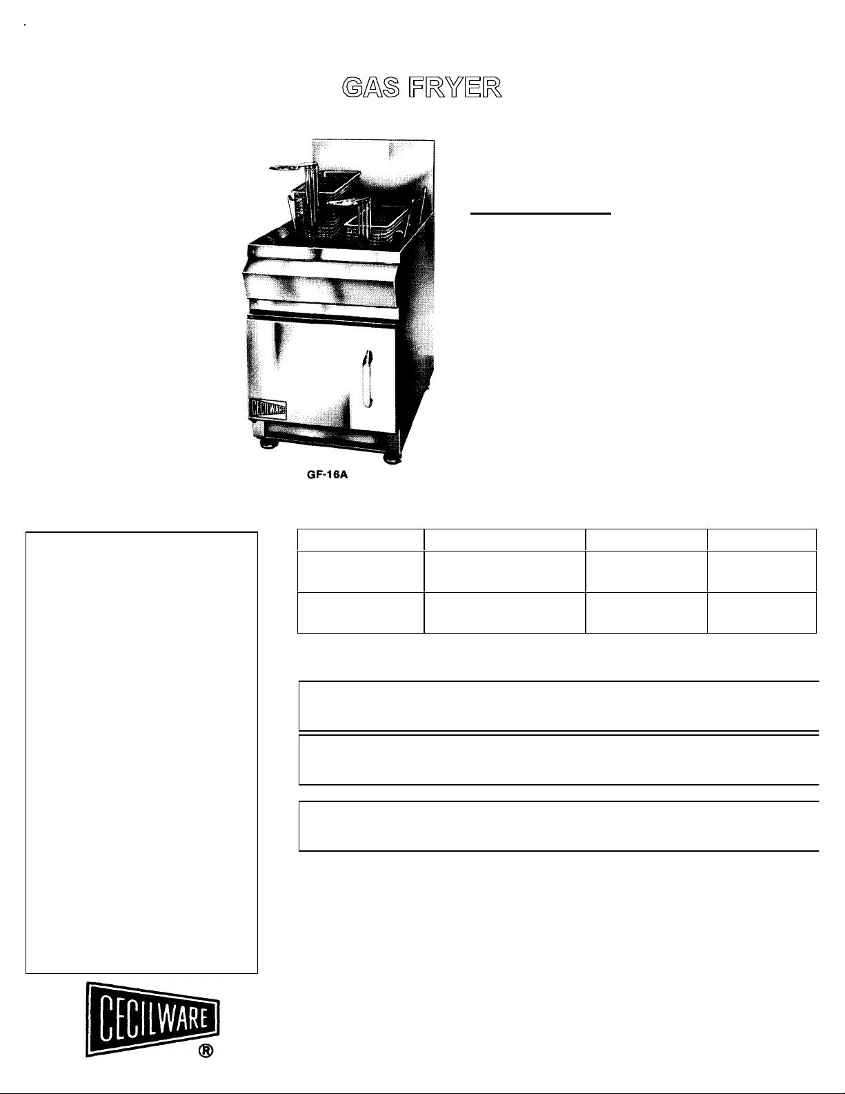
GF-16A
CONTENTS
WARRANTY
COMMERCIAL HEAVY DUTY
• GAS DATA • OPERATION
• GENERAL SPECIFICATIONS • MAINTENANCE
• UNPACKING AND INSPECTION • ADJUSTMENTS
• INSTALLATION • PARTS LIST
GF-28A
FM-28A
Every Cecilware product has been
carefully inspected before shipment. The
finest of materials and the highest
standards of workmanship have been
built in to the equipment.
Within 1 year of purchase, should any
Cecilware product show defect in
factory workmanship or material, we
agree to repair, at our option or replace
without cost to user such parts which
prove upon factory inspection to have
been so defective. All equipment must
be shipped transportation charges
prepaid for acceptance. This warranty
covers replacement parts only, labor
charges are covered for 90 days after
installation.
This warranty does not apply under the
following conditions:
• neglect or abuse of equipment
• excessive lime condition
• improper installation
• any outside modification to equipment
Every Cecilware urn body is covered for
three years. This warranty covers the
stainless steel body and stainless steel
liners only.
Portable equipment such as Electric
Fryers, Food Warmers, Electric Stoves,
Dispensers, Plug-In Urns, Coffee
Brewers and Warmers must be returned
to the factory or brought to an
authorized service station for repair.
STANDARD FEATURES:
• Quality construction
• Heavy duty 18 gauge Stainless Steel Unibody Construction for long life.
Welded for leakproof operation.
• 16 gauge Stainless Steel Heat Tube exchangers for maximum heat
transfer.
• Heavy duty cast iron burners.
• Drain valve slanted for fast draining of fats.
• Designed for maximum accessibility and service.
• Large foaming area.
• Automatic temperature control.
• Precision Thermostat for sogg-free frying.
• Super fast heat up and recovery seals and cooks food to perfection.
• Design certified by A.G.A.
• NSF Listed
• MEA Listed
SPECIFICATIONS
MODEL NO. BTU GAS INPUT TYPE GAS FAT CAP.
GF-28A
FM-28A
GF-16A
DO NOT store or use gasoline or other flammable vapors and liquids in the vicinity of this or any
other appliance.
This installation must conform with local codes, with the National Fuel Gas Code ANSI
Z22.1 (latest edition), Natural Gas Installation Code, CAN/CGA - B149.1 the Propane
Installation Code, CAN/CGA • B149.2 as applicable.
WARNING: Improper installation, adjustment, alteration, service or maintenance can
cause property damage, injury or death. Read the installation, operating and
maintenance instructions thoroughly before installing or servicing the equipment.
45000 @ 4 W.C.
41500 @ 10 W.C.
25000 @ 4 W.C.
22500 @ 10 W.C.
FOR YOUR SAFETY
NATURAL
PROPANE
NATURAL
PROPANE
28 LBS.
28 LBS.
18 LBS.
18 LBS.
CECILWARE CORPORATION
43-05 20th Avenue, Long Island City, NY 11105 (718) 932-1414 Fax (718) 932-
N231A12/98
Page 2

FOR YOUR SAFETY
DO NOT STORE OR USE GASOLINE OR OTHER FLAMMABLE VAPORS AND
LIQUIDS IN THE VICINITY OF THIS OR ANY OTHER APPLIANCE.
SAFETY PRECAUTIONS
FOR YOUR SAFETY, THE FOLLOWING SAFETY PRECAUTIONS SHOULD BE
FOLLOWED AND ENFORCED.
1. Instructions must be posted in a prominent location and all safety precautions taken in the event the
user smells gas. Obtain this information from your local gas supplier. IF YOU SMELL GAS
1. OPEN WINDOW 3. EXTINGUISH ANY OPEN FLAMES
2. DON'T TOUCH ELECTRICAL SWITCHES 4. IMMEDIATEL Y CALL YOUR GAS SUPPLIER
2. LIGHTING - Follow the instructions on page 3 and on label attached to side of unit.
3. DO NOT place anything over the flue opening.
4. DO NOT place combustible or non-combustible materials in the vicinity of the hot plate as this could
cause fires or obstruct air to the main burners.
5. This installation must conform with local codes, or in the absence of local codes, with the National Fuel
Gas Code, ANSI Z22.1 (latest edition), or the Natural Gas Installation Code, CAN/CGA-B149.1, or the
Propane Installation Code, CAN/CGA-B149.2 as applicable.
6. Provide adequate air supply and ventilation.
7. Provide adequate clearance for air openings into the combustion chamber.
8. Provide clearances for servicing and proper operation. This unit must be placed on a non-combustible
surface. Minimum clearances from combustible and non-combustible construction: 6 inches from side
and 6 inches back.
9. Unit plate must be disconnected from gas supply during any pressure testing of pipelines in excess of
1/2 psig (3.45 KPa), and insolated by turning off manual gas shut-off valve during any testing equal to or
less than 1/2 psig.
10. Retain this manual for future reference.
INSTALLATION AND OPERATING INSTRUCTIONS
UNPACKING: Carefully remove unit from container and inspect to any damage due to shipping.
CAUTION: Examine the gas specification label attached to the door panel to be certain that the type of gas for
which the unit is equipped is the same as the gas supply available.
INSTALLATION: Legs (in a plastic bag) are shipped with unit. To install legs, carefully tip the fryer up on its back
and screw the four legs into the threaded brackets on the bottom of the fryer. Select a location and level unit
by turning the leg adjustment screws (12) as indicated in the drawing.
GAS HOOK-UP: (For Installation Code see note 5 above). The fryer comes equipped with a 3/8" NPT Pressure
Regulator (4" W.C. for Nat. Gas and 10" W.C. for Propane) which is located between the manifold pipe and the
3/8" NPT gas inlet pipe. The size of the supply pipe to the fryer is very important for peak performance. Check
with your local gas company as to the proper pipe size. A manual gas shut -off valve should be installed between
gas supply line and fryer.
Check for gas leaks with soap and water solution before attempting to light the fryer. Adequate ventilation should
be provided where the fryer is installed.
DO NOT CONNECT THE FRYER FLUE DIRECTLY TO A BUILDING EXHAUS T PIPE.
FILLING FRY TANK: Always use top grade commercial shortening with high smoke point and resistance to
breakdown. Result: Longer fat life and better tasting food.
Be certain that the drain valve is closed before filling the fat container. Fill the fry tank with cooking compound to
the level line at the rear of the fat container or two inches above the top of the burner tubes.
NOTE: If solid fat is used, make sure that it is packed in solid and between the heat tubes and on the top before
lighting the unit. Insufficient packing will cause the heat tubes to reach excessive temperatures and cause the fat
to bum. Damage to the tubes may also result. It is safest to melt the shortening gradually by turning the burners
on and off for seconds until the tubes are covered with melted shortening.
2
Page 3

POSITIONING OF FRYER
The Fryer must be placed in operating position in such a way that accidental tipping of unit, or spilling of hot oil,
cannot occur.
The unit may be restrained by either:
1. Connecting unit in battery with others, or
2. Locating unit in an alcove, or
3. Using cable ties - as supplied with units with casters.
4. Activating foot brakes on casters once unit is in final position.
MOVING THE FRYER
Moving a unit with hot oil in the tank may cause spilling of oil which can cause serious burns or broken bones due to
slipping on oil. Thus, if it becomes necessary to move a Fryer to a new location, the following precautions should be
taken:
1. Allow oil in tank to cool to a low enough temperature so it can be transferred to storage containers. WEAR
EYE PROTECTION WHEN TRANSFERRING HOT OIL.
CAUTION: In the case of plastic transfer containers - make sure the oil is cool enough not to melt the
container.
2. Disconnect gas line.
3. Remove restraints and relocate the unit.
4. Secure unit properly in new location before reconnecting the gas line.
DO NOT LIGHT GAS UNTIL TANK HAS BEEN FILLED WITH OIL.
5. Reload the oil.
3
Page 4

LIGHTING INSTRUCTIONS: Follow the lighting instructions as outlined on the door of the fryer. NOTE: When the fryer is lit for the first
time, it may take a little longer to light the pilot until the air is purged out of the system.
LIGHTING INSTRUCTIONS (See Illustration on pg. 4)
1. Set the thermostat knob to "OFF" position.
2. Turn the gas cock valve (A) to the position where the word "pilot" lines up with the red button (B).
3. Depress the red button (B) and apply a lighted match to the pilot (C). Hold the red button in the depressed
position for approximately 60 seconds and then release, the pilot should remain lit. If the pilot flame is not
approximately 1" long, make the necessary adjustments by following the instructions for pilot flame
adjustments.
4. Turn the gas cock valve (A) so that the word "ON" lines up with the red button.
5. To ignite the main burners, rotate the thermostat dial (D) to the desired frying temperature.
6. For stand-by periods, turn the gas cock valve (A) to the pilot position by lining up the word pilot with the red
button.
7. To shut the fryer down completely, line up the word "OFF" with the red button (B) while lifting the unlocking
(J) pin to accomplish this setting.
RELIGHTING - Shut off all gas and wait 5 minutes before relighting pilot.
OPERATION—Set your thermostat dial for the recommended temperature and allow the fryer to pre-heat. Pre-heat time from room temperature to
350 degrees is about 10 minutes. While pre-heating, the main burners will be lit and when the pre-set temperature is reached, the thermostat will
automatically shut off the main burners. The pilot will remain lit and the precision thermostat will automatically control the fat temperature at this
setting until the setting is changed or the gas is shut off.
A safety control system is built into the fryer which automatically shuts it off when the temperature of the fat exceeds 450° degrees. If this condition
should occur, turn the thermostat to "OFF" and allow the fryer to cool. Wait at least 5 minutes before relighting pilot. If this condition should repeat, call a
factory authorized service agency.
Fry baskets should be loaded to one half and never more than two-thirds their capacity; overloading always results in an improperly cooked
product. After the food has been cooked, lift the baskets out of the fat and hang them on the basket supports for drainage.
MAINTENANCE —The fat container of your fryer will give you many years of service if you drain and clean it daily. CAUTION: Open drain valve
(20) slowly to prevent splashing grease when draining tank. Use a suitable fryer cleaner and follow directions on the package. Strain or filter
used frying compound before replacing in fat container. Make sure drain valve is closed before refilling fat container.
Clean lint and dirt off air shutters on main burners periodically. After longer periods, burners and pilot should be cleaned for proper ignition and
burner flame efficiency.
Valves and automatic controls should be serviced only by a qualified service person.
ADJUSTMENTS
PILOT—The pilot flame can be adjusted by first removing the pilot adjustment cap (F) located directly behind the gas cock valve. When the cap is removed,
it will reveal an adjustment screw that should be turned counter-clockwise to raise it. Pilot flame should be adjusted to maintain a flame of approximately 1"
long for proper ignition of the main burners. Replace pilot adjustment cap after adjustments are completed.
BURNERS- Fixed orifices and a pressure regulator set at 4" W.C. NAT and 10" W.C. PROP. control the gas input to the main burners. Adjust air shutters
on burners to obtain a flame with a soft blue inner cone.
THERMOSTAT—Place a fryer thermometer in the fat and light main burners. Turn thermostat dial to 350° F and allow fat to heat. When the flames
on the main burners go out, compare the reading of the thermometer with the setting of the thermostat dial. If the temperature does not coincide
within a few degrees, proceed as follows:
Turn the thermostat dial to 375° and remove dial assembly without disturbing the setting. A small screw will be visible in the center of the
thermostat shaft. Observe the temperature of the thermometer in the fat and when it approaches 375°, slowly turn the adjusting screw in the center
of the thermostat shaft clockwise until the flames on the main burners go out. Turning the screw counter-clockwise will increase the temperature.
Conversely, turning the screw clockwise will decrease the temperature. Replace the thermostat dial.
HIGH LIMIT THERMOSTAT— This thermostat is set at 450° F at the factory and should not be adjusted in the field. If the fat temperature exceeds
the setting by 15° F, replace the high limit control.
Contact a factory representative or a local service company if major repairs or maintenance is required.
4
Page 5

PARTS LIST
G088A(PROP)
GF-16A, GF-28A, FM-28A
FIG. NO. ITEM GF-16A GF-28A, FM-28A FIG. NO. ITEM GF-16A GF-28A. FM-28A
1 Orifice F117A(NAT) F124A(NAT) 23 Hi Limit Control L112A L112A
F168A(PROP) F168A(PROP) 24 Thermocouple W/Junction F002A F002A
2 Orifice Stem K015A K015A 24A Wire Ass'y. L113A L113A
12 Leg (4 per set) M042A M042A M002A (FM-28A) 24B Adaptor L115A L115A
14 Pilot F131A(NAT) F131A(NAT) 25 Burner G084A(PROP) G087A(NAT) left
F132A(PROP) F132A(PROP)
15 Pilot Tube (Alum.) H054A H035A
17 Air Shutter F016A F016A
19 Thermostat L099A L099A 26 1/4-20 Wing Nut P103A P103A
20 Drain Valve D005A D005A 34 Burner Clamp
21 Baso Safely L016A L016A 37 Manifold
22 Gas Pressure Regulator L043A(NAT) L359A(NAT) 38 Brass EL K029A K075A
L198A(PROP) L198A(PROP) 39 Thermostat Knob Red M099A M099A
G085A(NAT) G089A(NAT) right
G086A(PROP) left
U240A
F029A
5
 Loading...