

Page 1
Oatmeal Dispenser
Operator Manual
Model GB3-LPO
Safety Information..................2
Installation...............................3
Operation ................................5
Cleaning...................................6
Maintenance ...........................7
Troubleshooting Guide...........9
Parts List.................................10
Thank you for purchasing this quality oatmeal dispenser. For your safety and the safety of others, read all warnings
and the operator manual before installing or using the product. Properly instruct all operators. Keep training
records. For future reference, record serial number here:
Table of Contents
Grindmaster-Cecilware
4003 Collins Lane, Louisville, KY 40245 USA
Phone: 502.425.4776 Toll Free: 800.695.4500
Fax: 502.425.4664
Web: gmcw.com Email: info@gmcw.com
©2016 Grindmaster-Cecilware
Printed in USA
0516 Form # CW-325-01
Part # 390-00061
Grindmaster-Cecilware provides the industry’s
BEST warranty. Visit gmcw.com for warranty
terms and conditions.
Page 2
Lifting hazard. Single person lift could cause injury. Use assistance when moving or lifting.
For safe and proper operation, the appliance has to be placed in a stable, vertical position.
The appliance is not to be used by persons with reduced physical, sensory, or mental capabilities, or lack of
experience and knowledge, unless they have been given supervision or instruction. Be sure to provide supervision
or instruction concerning use of the appliance in a safe way and understand the hazards involved.
Children must be supervised to ensure they do not play with the appliance.
The appliance is only to be installed in locations where it can be overseen by trained personnel.
CAUTION
To avoid damaging unit, turn on power and wait for tank to fill with water before turning on heater.
Observe machine voltage configuration. Do not apply improper voltage to machine or damage to machine will
occur.
Do not use extension cord.
NOTICE
The appliance is not intended for outdoor use.
Do not clean with pressurized water or use in an area where pressurized water may be used.
Cleaning and maintenance shall be made only by properly trained persons with supervision.
WARNING
Safety Information
2 Cecilware
®
GB Series Oatmeal
Important Safety Information
This is the safety alert symbol. It is used to alert you to potential personal injury hazards. Obey all safety messages
that follow this symbol to avoid possible injury or death.
For your safety and the safety of others, read all warnings and the operator manual before installing or using
the product.
DANGER: This term warns the user of imminent hazard that will result in serious injury or death.
WARNING: This term refers to a potential hazard or unsafe practice, which could result in serious injury or death.
CAUTION: This term refers to a potential hazard or unsafe practice, which could result in minor or moderate
injury.
NOTICE: This term refers to information that needs special attention or must be fully understood.
Page 3
CAUTION: Lifting hazard. Single person lift could
cause injury. Use assistance when moving or lifting.
Unpacking Instructions
Carefully unpack the Oatmeal Machine and inspect
immediately for shipping damage. Your Oatmeal
Machine was shipped in a carton designed to give it
maximum protection in normal handling. It was
thoroughly inspected before leaving the factory. In
case of damage, contact the shipper, not GrindmasterCecilware.
After the machine has been unpacked and placed on a
counter, pull out the stainless steel drip tray. It should
contain the following:
• 1/4” Flare Water Inlet Fitting.
Water Inlet Connection:
NOTICE: This equipment is to be installed to comply
with the applicable Federal, State, or local plumbing
codes having jurisdiction. In addition:
1. A quick disconnect water connection or enough
extra coiled tubing (at least 2x the depth of the
unit) so that the machine can be moved for
cleaning underneath.
2. An approved backflow prevention device, such as
a double check valve to be installed between the
machine and the water supply.
The GB oatmeal dispenser is equipped with a ¼" Flare
Water Inlet fitting which is located on the left side in
the back of the base (when looking at the machine
from the front).
Water pipe connecting and fixtures directly connected
to a potable water supply shall be sized, installed, and
maintained in accordance with Federal, State, and
Local codes.
HIGHLY RECOMMENDED:
A WATER SHUT-OFF VALVE and A WATER FILTER,
preferably a combination Charcoal/Phosphate Filter, to
remove odors and inhibit lime and scale build up in the
machine.
Note: In areas with extremely hard water, a water
softener must be installed in order to prevent mineral
deposits that could lead to malfunctioning of the
equipment and in order not to void the warranty.
GB Series Oatmeal Cecilware
®
3
Installation
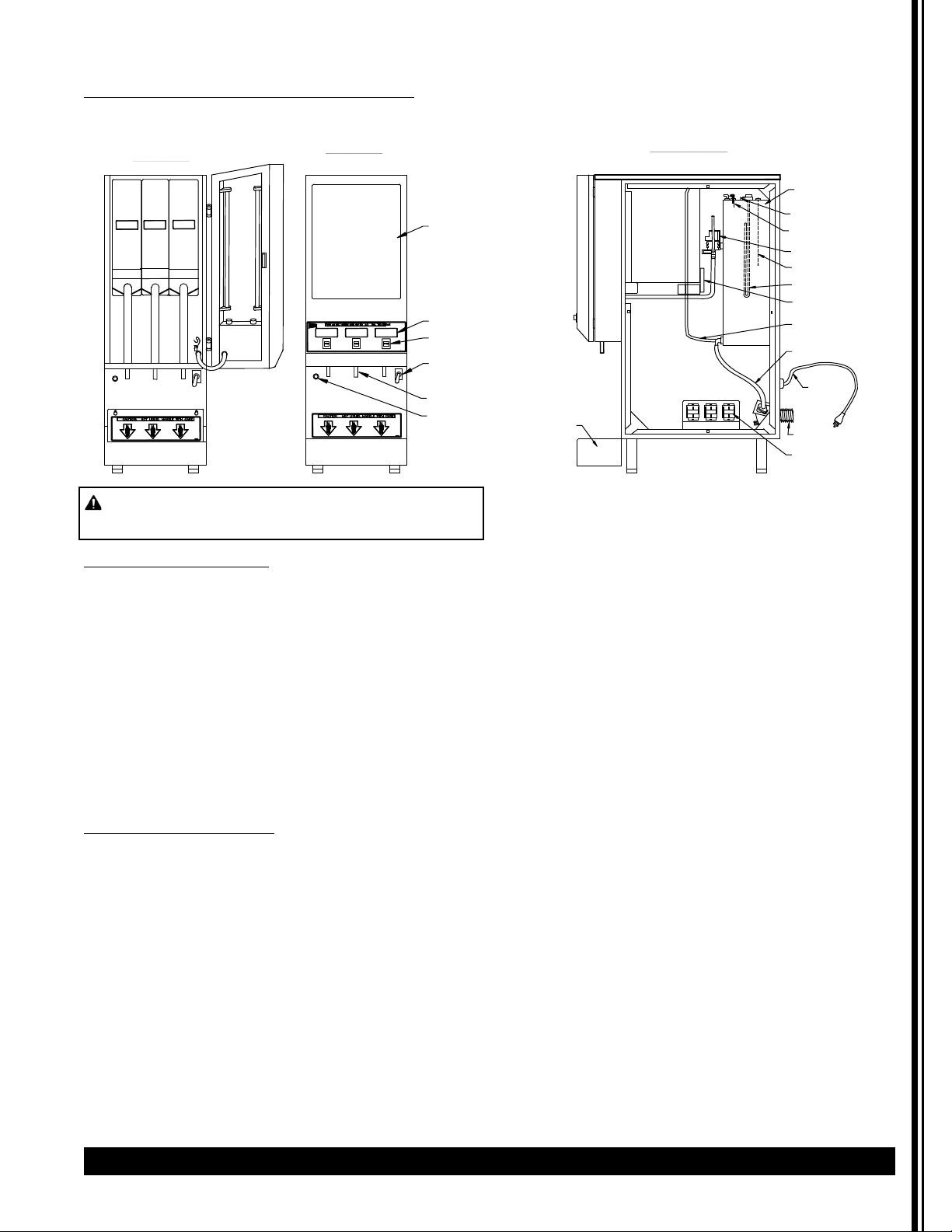
Description and Location of Components
Note: Refer to following illustration for description and location of COMPONENTS and CONTROLS.
FRONT VIEW
4 lb.
4 lb.
DRIP TRAY
4 lb.
FRONT VIEW
DRIP TRAY
LABEL AREA
PRODUCT LABEL
DISPENSE BUTTON
POWER SWITCH
SPOUT (3)
PILOT LIGHT FOR
HEATER
RIGHT SIDE VIEW
TANK ASS'Y
HI-LIMIT (TEMP)
WATER LEVEL CONTROL
DISPENSE VALVE
THERMISTOR PROBE
HEATER ASS'Y
AUGER MOTOR
DRAIN HOSE W/PLUG
WATER INLET HOSE
POWER
CORD
DRIP TRAY
WATER INLET VALVE
RELAY/TIMER
Page 4

1. HOPPERS: Depress the door latch on the left
side of the door and pull door open to access
the hoppers.
• The hoppers hold up to 4 lbs. (1.8 kg) of
Oatmeal product.
• To remove the hoppers, swing the top
compartment door open and lift out the
hoppers.
• To reposition the hoppers in the
compartment, slide the hopper base back
between the rails until the 1/4" pin at the
bottom of the hopper base falls into the 1/4"
positioning hole of the compartment base
cover.
2. HEATER SWITCH: This switch is located inside
the cabinet behind the right hopper; open door
and remove right hopper to access it.
• Its primary function is to shut off the heating
element during the initial priming, start-up
operation of the machine, or whenever the
tank is being drained for service.
Note: The Power Switch and Heater Switch must
be ON in order for the elements to operate.
3. POWER SWITCH: This switch is located on the
left side of the splash panel below the door.
Note: The Power and Heater Switches are
independent of each other. Both switches must
be OFF in order for the machine to be
completely shut down.
4. WATER LEVEL CONTROLS: Under normal
conditions and operation, the water level in the
tank should not drop more than 1/2" (1.3cm)
from the probe. If it does, the tank is not
refilling fast enough. Check the water line and
water filter; they may need cleaning or
replacing.
1. Tank Control Board Part# 349-00012
2. Water Inlet Valve Part# L462AL
3. Water Level Sensor Part# K695QL
Start-up Procedure
NOTICE: Make sure that the Heater Switch, located
behind right hopper with door opened, is in the OFF
position.
1. Connect the 1/4" dia. copper waterline to the
1/4" flare water inlet fitting of the valve.
2. Plug the power cord into a proper receptacle.
3. Activate the Power Switch (Toggle Up). The
door display panel, the red power indicator
light and the green dispense buttons will light
up and the tank will start filling. Allow
approximately 4-5 minutes for the tank to fill.
4. Activate the Heater Switch. Allow
approximately 10-30 minutes for the water to
reach a temperature of 190°F (88°C). The heat
up time will depend on the water inlet
temperature.
5. Place an 8 oz. (240ml) or larger cup under the
left dispense nozzle, press and hold the left
dispense switch for 6 seconds. The machine will
dispense water at the rate of 1 oz. (30ml) per
second. Repeat it several times to check for
consistent output. Repeat same for the other
dispense switches. This procedure checks that
the dispense valves are not air-locked.
6. While the tank is heating, remove the hoppers,
load them with products, and reposition them
back in the machine. When the green ready
light comes on, the tank has reached its brew
temperature and the machine is ready to
dispense the first cup of Oatmeal.
Filling the Hoppers
1. To remove the hoppers, swing the top
compartment door open and lift out the
hoppers.
2. Fill each hopper with the correct product.
3. Reposition hoppers in the hopper
compartment, making sure the hoppers are
properly seated.
If you need help, call Grindmaster-Cecilware Technical
Service Department, (502) 425-4776 or (800) 695-4500
(USA & Canada only) 8 AM - 6 PM EST.
Prior authorization must be obtained from
Grindmaster-Cecilware for all warranty claims.
4 Cecilware
®
GB Series Oatmeal
Installation (continued)
Page 5

GB Series Oatmeal Cecilware
®
5
Your new oatmeal dispenser is easy to operate and
maintain. Before you place it in service, please have all
personnel familiarize themselves with these
instructions. Keep this manual in a convenient place for
ready reference.
How to Operate
To dispense a cup of Oatmeal:
• Place an 8 oz. (240ml) or larger cup under selected
drink dispense nozzle.
• Push and hold brew button until cup is 2/3 full, then
release button.
Adjustments
Water Flow Rate Adjustment
The Dispense Valves are factory adjusted for a
maximum Flow Rate of 1 to 1.3 oz./sec (30-38 ml/sec).
Note: To access the Water Dispense Valves, open door
and remove Hoppers.
Temperature Adjustment (Tank Control Board
Type)
1. Locate the Tank Control Board.
2. Press button under right side of display to increase
temperature.
3. Press button under left side of display to decrease
temperature.
4. Pressing both buttons simultaneously will reset to
default 190°F (88°C).
Temperature Adjustment (Thermostat Type)
1. Locate Thermostat: Remove the right side panel.
Thermostat is mounted on side of tank.
The GB oatmeal dispensers are factory set to deliver
hot brewing water at 190°F (88°C).with the
thermostat knob turned to full ON position. If
adjustments should be necessary to increase or
decrease the water TEMPERATURE, proceed as
follows:
Note: Set the Rinse Switch to ON. This will disengage
the Hopper Motors when dispensing water for
Temperature measurements.
2. To INCREASE the water temperature - With the
Thermostat Knob to its maximum clockwise
position, remove the knob and locate the slotted
adjustment screw inside the hollow thermostat
shaft. Using a narrow-bladed screwdriver, engage
slotted adjustment screw and turn it ¼ turn slowly
counter-clockwise.
Allow a few minutes for the temperature to reach
set level. The Heater Light will go ON, indicating the
heating element is activated, wait for it to go OFF,
indicating that the water has reached new set
temperature. Take a temperature reading and
repeat if necessary.
3. To DECREASE the water temperature - simply turn
the Thermostat Knob one notch counter-clockwise
to the next lower dial setting.
Display
Decrease
Increase
190°
Operation
TO ADJUST WATER FLOW RATE:
1. Open door and remove hoppers. Locate Dispense
Valve behind hoppers, mounted on tank.
2. Locate adjustment screw on Dispense Valve.
3. Using Allen Key or flat screwdriver rotate, 1/4 turn
at a time,
CLOCKWISE to decrease water flow, or
COUNTERCLOCKWISE to increase water flow.
4. Check water flow output, after each 1/4 turn.
WATER FLOW ADJUSTMENT
DISPENSE VALVE
Page 6

6 Cecilware
®
GB Series Oatmeal
NOTICE: All sanitizing agents in the food zone must
comply with 21 CFR 178.1010.
Sanitize all food dispensing units periodically. All parts
to be sanitized must be cleaned first. Cleaning and
sanitizing frequency must follow state and local health
department regulations.
Daily maintenance:
1. Remove Hoppers
• Position a container under dispense tubes.
• Push and hold each dispense button 10 seconds.
2. Empty drip tray, wash, rinse, and sanitize.
3. The outside of the machine can be cleaned with
warm soapy water and a damp cloth.
Weekly maintenance:
Product hopper cleaning
• Rotate product guides up, remove hoppers from
machine.
• Empty powder into pans.
• Pull off product guides.
• Remove agitator wheels.
• Unscrew and remove front and back auger locks.
• Remove auger.
• Wash, rinse, sanitize, and air dry all small parts.
• Wash & scrub hoppers and agitator wheel recesses
with bristle brush. Rinse, sanitize, and allow to air
dry.
• Reassemble all hoppers.
• Pour powder into hoppers.
• Install all hoppers into unit.
Sanitizing
1. Prepare a sanitizing solution in accordance with
local health department regulations. You may also
refer to the US Food and Drug Administration
regulation 21 CFR 178.1010 “Sanitizing Solutions”
and US Environmental Protection Agency 40 CFR
18.940 “Tolerance exemptions for active and inert
ingredients for use in antimicrobial formulations
(Food-contact surface sanitizing solutions)”.
2. Follow the instructions provided with the sanitizing
agent.
3. Let all sanitized parts drain and air dry. DO NOT
WIPE THEM DRY.
Cleaning
HOPPER COVER
AGITATOR GEAR
AGITATOR WIRE
AUGER BUSHING-FRONT
AUGER
PRODUCT GUIDE
AUGER MOTOR
NUT [2]
FLANGE/ NUT
AUGER BUSHING-BACK
Page 7

GB Series Oatmeal Cecilware
®
7
Maintenance
Lit Display Replacement
1. Lift up the two end tabs on top of door with a
pointed object or flat head screwdriver.
2. Pull the entire picture frame out. Open the two
clear panels and replace picture.
3. Tuck clear plastic panel inside bracket at top.
4. Be sure to tuck clear panel under bracket before
sliding frame assembly inside door.
5. The longer metal tab side goes in the front.
Recommended preventive maintenance
1) Dispense Valves
• Check all dispense valves for lime build-up.
• Drain the water tank to just below the level of the
dispense valves.
• Remove the valves and clean. (Take these valves
apart byhand as shown).
• Replace the assembly as needed (L467AL -120V or
L676AL - 230V import).
Replace the valve into the tank and refill tank.
WARNING Riskof electrical shock. Turn off power
to unit before replacing bulb or starter.
T
C
U
D
P
O
R
L
A
B
E
L
WATER FLOW ADJUSTMENT
Page 8

Component Tests
Dual Probe Test
If lack of water persists, check the probe as follows:
1. Turn on the power and water supply.
2. Check inside the tank to make sure the water is
below the Probe.
3. Pull the BLUE wire and terminal OFF the Probe rod.
If water still does not flow after the wire is
disconnected from the Probe, the problem may be
in the Tank Control Board.
4. If water starts flowing into the tank, the Probe may
be grounded, due to excessive liming. Check with
Ohm meter. Clean probe.
Water Inlet Valve Test
1. Turn power OFF. If the water level rises inside a
partially filled tank, the Water Inlet Valve is leaking.
2. Disconnect wires from the Water Inlet Valve coil and
connect a 2 wire line cord to the terminals. Plug it
into a 115V outlet. If water flows in and stops when
you pull it out, the Valve is working correctly.
Repeat this test a few times. The problem may be
in the Probe or Water Level Control Board.
3. If the water does not flow in when the cord is
plugged into an electrical outlet, the Solenoid coil
may be damaged, opened or the valve may have an
obstruction preventing the water from flowing in.
Clean or replace it.
Water Level Controller Test
(For models manufactured 2015 and prior)
Check the Controller as follows:
1. Make sure there is power input to the Controller at
the terminals AC1 & AC2
Your voltmeter should read 115 Volts. It should read
the same at terminals AC1 & FILL when the water
level is low. This is the output power to actuate the
coil of the Solenoid Valve to open it. The lack of
voltage at terminals AC1 & L-LEVEL or H-LEVEL
indicates that the Controller is not working
properly.
2. Make sure all wire connections are tight, including
ground.
3. If after this, the Controller is still failing to open the
Water Inlet Valve, replace it.
8 Cecilware
®
GB Series Oatmeal
Maintenance (continued)
BLUE
DUAL
PROBE
DUAL PROBE LIQUID LEVEL
CONTROLLER
TO
N
SOLENOID
TO PROBE
L1
HOSE NUT ASSY
GROUNDING
PLATE IN
BACK OF THE
BOARD
GROUND
TERMINAL
SS WATER LEVEL CONTROL CCA
4
T5
SINGLE L398C [120V]
DUAL L690A [120V]
SINGLE L399C [220V]
DUAL L706A [220V]
1
2
3
WATER INLET VALVE
Page 9

GB Series Oatmeal Cecilware
®
9
Troubleshooting Guide
Before you call for help, please read the following:
WARNING: To reduce the risk of electrical shock, unplug the dispenser power cord before repairing or
replacing any internal components of the unit. Before any attempt to replace a component, be sure to check all
electrical connections for proper contact.
Problem Possible Cause Solution
Light Display not lit.
No power.
Dispensing unit unplugged. Reconnect dispensing unit.
No power from Terminal Block. Check the Terminal Block for loose wire.
Defective Bulb. Replace Bulb.
Defective Ballast. Replace Ballast.
Loose Bulb in socket. Make sure bulb is seated properly in socket.
No water when Rinse
Switch is ON.
Water supply OFF. Turn water ON.
Clogged inlet screen (Water Inlet Valve). Disconnect water line and clean inlet screen.
Inoperative Water Inlet Valve. Check connection, if needed replace Valve.
Loose electrical connection. Check all electrical connections.
No product when Dispense
Button is pressed.
No product in Hopper. Add product.
Auger not working. Engage Hopper/Nut to Motor Gear.
(See pg 6).
Damaged, loose, or missing Agitator Replace Agitator Gear (See pg 6).
Gear.
Inoperative Auger Motor or Relay. Check connections of Motor, Relay, and/or
Switch; if needed replace components.
Hopper outlet clogged. Clean Hopper and check Cartridge Heater.
Faulty Coupling. Replace damaged Coupling components.
Water does not shut off.
Water keeps dispensing.
Leaking Water Inlet Valve. Clean/check fittings of Water Inlet Valve.
Replace Water Inlet Valve if needed. See
Water Inlet Valve Test.
Inoperative Dispense Switch. Check Switch connections. Replace Dispense
Switch if needed.
Inoperative Rinse Switch. Check Rinse Switch connections.
Replace Rinse Switch if inoperative.
Clogged/stuck Water Dispense Valve. Clean or unclog Water Dispense Valve.
Replace Dispense Valve if inoperative.
No water is going into tank
at all.
Water Inlet Valve malfunction. Check Solenoid. Replace if necessary.
See Water Inlet Valve Test.
Water Level Sensor/ Probe malfunction. Check Probe. Replace if necessary. See
Probe Test.
Solid State Level Control Board. Check Water Level Controls. Replace if
necessary. See Water Level Controller
Test.
Water will not stop flowing
into water tank.
Water Level Probe malfunction. Check Probe. Replace if necessary. See
Probe Test.
Solenoid (Water Inlet Valve) malfunction. Check Solenoid. Replace if necessary. See
Water Inlet Valve Test.
Solid State Water Level Control
malfunction.
Check the Water Level Controls. Replace if
necessary. See Water Level Controller
Test.
Water is not heating up in
the water tank.
Heater Switch is OFF. Turn Heater Switch ON.
Thermostat is OFF. (Only models with
separate Thermostat)
Turn Thermostat ON. Turn Knob Clockwise.
Loose connection on Thermostat. Make sure all wires and terminals on
Thermostat are tight.
Hi-Limit Temperature Switch is defective. Replace the Hi-limit.
Heater is burned out or defective. Replace the Heater.
Page 10

Troubleshooting Guide (continued)
If you still need help, call Grindmaster-Cecilware Technical Service Department, (502) 425-4776 or (800) 695-4500
(USA & Canada only) (Monday through Friday 8 AM - 6 PM EST). Please have the model and serial number ready
so that accurate information can be given.
Prior authorization must be obtained from Grindmaster-Cecilware for all warranty claims.
Grindmaster-Cecilware provides the industry’s BEST warranty. Visit our website at GMCW.com for
warranty terms and conditions.
Parts List
Hopper Parts
HOPPER ASS'Y CD152L, 4 LB, 11.5"H x 3"W, W/WIRE AUGER CD101L
HOPPER COVER CD106L
AGITATOR GEAR
CD117
AGITATOR WIRE
AUGER BUSHING-FRONT CD277L
WIRE AUGER
CD101L (22.5Øx18mmPT)
PRODUCT GUIDE 63700
AUGER MOTOR CD175L
NUT [2] CD278L
FLANGE/ NUT CD340L
AUGER BUSHING-BACK CD279L
Page 11

GB Series Oatmeal Cecilware
®
11
Parts Diagram and List (continued)
Tank Parts
2.8 GALLON TANK
Page 12

Parts Diagram and List (continued)
Unit Parts
Grindmaster-Cecilware
4003 Collins Lane, Louisville, KY 40245 USA
Phone: 502.425.4776 Toll Free: 800.695.4500
Fax: 502.425.4664
Web: gmcw.com Email: info@gmcw.com
©2016 Grindmaster-Cecilware
Printed in USA
0516 Form # CW-325-01
Part # 390-00061
 Loading...