

Page 1
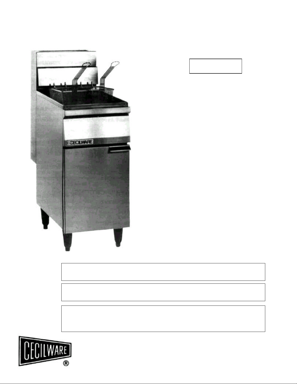
COMMERCIAL
GAS FRYER
MODEL FMP-403
CONTENTS
• GAS DATA • OPERATION
• GENERAL SPECIFICATIONS • MAINTENANCE
• UNPACKING AND INSPECTION • ADJUSTMENTS
• INSTALLATION • PARTS LIST
STANDARD FEATURES:
• Quality Construction
• 14 gage Mild Steel Tank Heliarc
Welded for leak proof operation.
• 16 gage Stainless Steel Heat Tube
exchangers for maximum heat transfer.
• Heavy duty cast iron burners.
• 1 ¼” ball type drain valve for fast draining of fats.
• Designed for maximum accessibility and service.
• Large foaming area.
• Automatic temperature control.
• Precision Thermostat for sogg-free frying.
• Super heat up and recovery seals and cooks food to
perfection.
DO NOT STORE OR USE GASOLINE OR OTHER FLAMMABLE VAPORS AND LIQUIDS
WARNING: IMPROPER INSTALLATION, ADJUSTMENT, ALTERATION OR
MAINTENANCE CAN CAUSE PROPERTY DAMAGE, INJURY OR DEATH. READ
THE INSTALLATION, OPERATION AND MAINTENANCE INSTRUCTIONS
THOROUGHLY BEFORE INSTALLING OR SERVICING THIS EQUIPMENT.
FOR YOUR SAFETY
IN THE VICINITY OF THIS OR ANY OTHER APPLIANCE.
THIS INSTALLATION MUST CONFORM WITH THE NATIONAL FUEL
GAS CODE ANSI Z223.1 (Latest Edition).
CECILWARE CORPORATION
43-05 20th Avenue, Long Island City, N.Y. 11105 • 718-932-1414
N900A 1/99
Page 2
FOR YOUR SAFETY
DO NOT STORE OR USE GASOLINE OR OTHER FLAMMABLE VAPORS AND LIQUIDS
IN THE VICINITY OF THIS OR ANY OTHER APPLIANCE.
SAFETY PRECAUTIONS
FOR YOUR SAFETY, THE FOLLOWING SAFETY PRECAUTIONS SHOULD BE FOLLOWED AND ENFORCED.
1. Instructions must be posted in a prominent location and all safety precautions taken in the event the user smells gas. Obtain this information from your local gas
supplier.
IF YOU SMELL GAS:
1. OPEN WINDOWS 3. EXTINGUISH ANY OPEN FLAMES
2. DON’T TOUCH ELECTRICAL SWITCHES 4. IMMEDIATELY CALL YOUR GAS SUPPLIER
2. LIGHTING - Follow the instructions on page 4 and on label attached to inside of fryer door.
3. Do not place anything over the flue opening.
4. Do not place combustibles or non-combustible materials in the vicinity of the fryer as this could cause fires or obstruct air to the main burners.
5. This installation must conform with local codes, or in the absence of local codes, with the National Fuel Gas Code ANSI Z223.1a -Latest Edition.
6. Provide adequate air supply and ventilation.
7. Provide adequate clearance for air openings into the combustion chamber.
8. Provide clearance for servicing and proper operation. Minimum clearance from combustible or non-combustible construction 6" from back and 6' from side.
9. Fryer must be disconnected from gas supply during any pressure testing of pipelines in excess of 1/2 psig, and isolated (by turning off
manual gas shut-off valve) during any testing equal to or less than 1/2 psig.
10. Retain this manual for future reference.
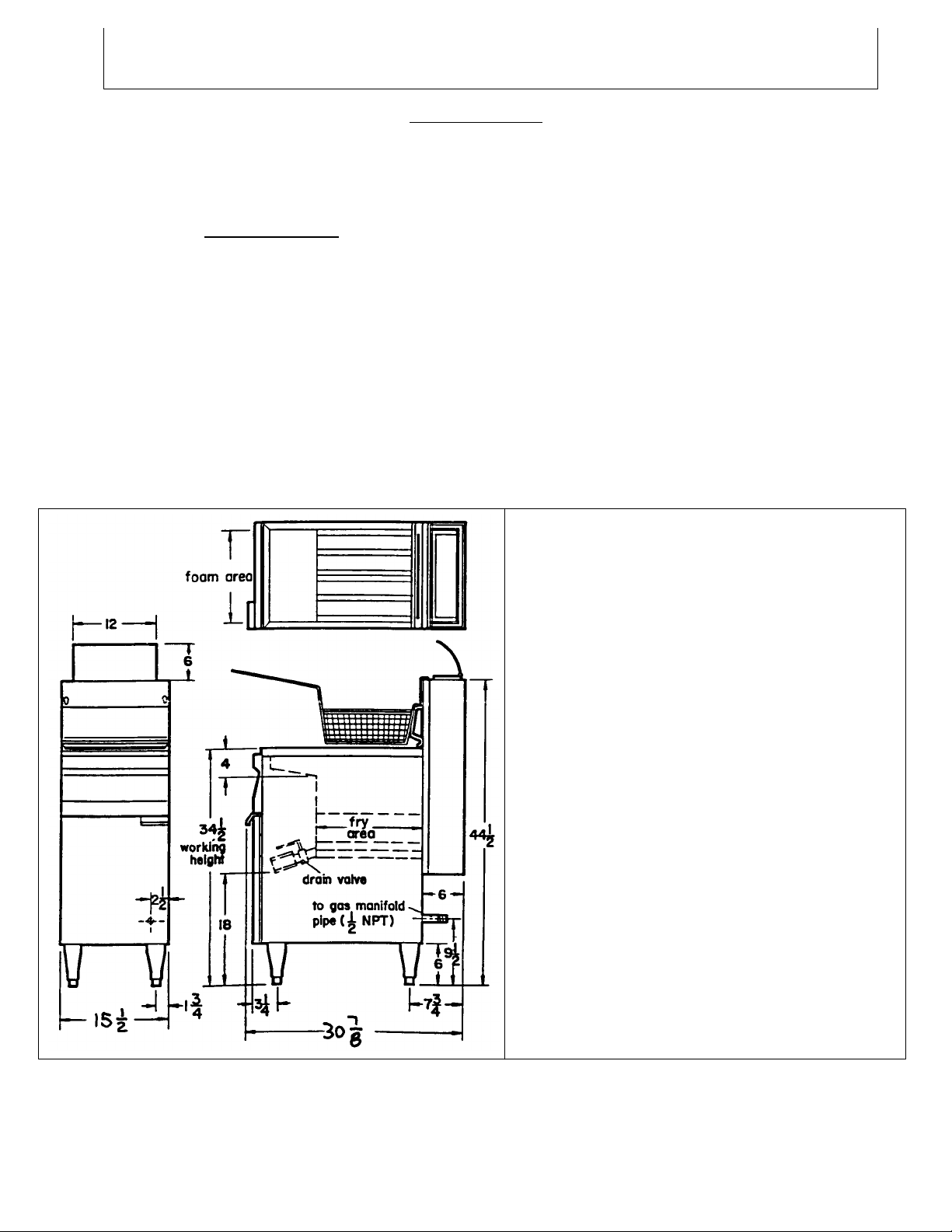
SPECIFICATIONS
GENERAL DATA
Width 15 ½”
Overall Depth 30 7/8”
Working Height 34 ½”
Overall Height 44 ½”
Fat Capacity 40 Ibs.
Foam Area 13 3/4" x 22"
Fry Area 13 3/4" x 13 ½”
Basket Size 12 1/8” x 6 ½” x 5 ¼”
Shipping Weight 180 Ibs.
Shipping Cube 14 cu.ft.
Gas Connection ½” I.P.S.
GAS SPECIFICATIONS
TYPE GAS MANIFOLD PRESSURE
Natural 4.0" W.C.
Propane 10.0" W.C.
TOTAL INPUT
Natural or Propane 90,000 BTU/HR
THIS FRYER INTENDED FOR OTHER THAN HOUSEHOLD
USE. CLEARANCE FOR COMBUSTIBLE CONSTRUCTION 6
INCHES FROM SIDE AND 6 INCHES FROM BACK.
2
Page 3

SECTION A - INSTALLATION AND OPERATING INSTRUCTIONS
A2 -
Accessories shipped in the vessel include:
A1 - Unpacking - With the container upright cut the plastic straps around shipping container and lift off top, exposing the Fryer. Check Fryer for any
visible damage due to exceptionally rough handling during shipping. Report damage to the delivering Freight Carrier within 15 days of delivery.
Accessories available as optional:
1 - Basket Hanger
2 - Baskets
1 - Drain Pipe Extension
1 - Flue Deflector Shield
4 - 6 inch Adjustable Legs
A3 - Mounting of Legs or Casters - Carefully tip Fryer up on its back and screw legs or (optional) casters into the threaded base of Fryer. When
installing casters make sure the swivel lock casters are mounted towards the front of Fryer. A high strength Restrainer and Quick disconnect Gas
Connector must be installed when casters are used. Avoid putting any strain on rear legs or casters when tipping Fryer back to an upright position.
A4 - Pre-installation Instructions - The installation of your Fryer must be made by a licensed plumber and the installation must conform with State
and Local Codes or in the absence of Local Codes, with the National Fuel Gas Code ANSI Z223.1 a-Latest Edition.
A5 - Air Supply and Ventilation - Adequate ventilation and air supply must be provided in order for the Fryer to operate property and efficiently. The
area in front of and above the Fryer must be clear to avoid any obstruction of flow of combustion and ventilation air. Do not. under any circumstances,
connect the Fryer flue directly to a building exhaust system or place the flue outlet directly into the plenum of the exhaust hood as it will adversely
affect the gas combustion of the Fryer.
1 - Cover
1 - Twin Basket
4 - Swivel Casters
1 - Quick Disconnect Connector 24"
and 36"
1 - Restrainer
The vent system should be of such design as to allow easy access for cleaning and degreasing on a regular basis in order to prevent fires. An
automatic fire extinguishing system should be an integral part of the vent design. Since the temperature of the flue gases emanating from Fryer flue
can reach 1200°F, temperature sensing devices of the automatic fire extinguishing system must be sized accordingly and located so as to avoid
premature turn-on. The minimum vertical distance from the top of Fryer flue to vent system filters should be 18 inches or more.
A6 - Clearances - Your Fryer is design certified for use on combustible floors. The minimum clearances for combustible and non-combustible
construction are as follows: 6 inches from SIDE and 6 inches from BACK. Fryer must be installed with 6 inch high legs or casters (optional). At least
16 inches clearance must be provided between frying surface of fryer and the surface flames from any adjacent cooking equipment.
A7 - Gas Connection - Before connecting Fryer to gas line, check the rating label on inside of door panel to make sure that the gas type called for on
label coincides with the type of gas available on sift. A 1/2 inch NPT gas pipe connection is provided at the rear of Fryer. An accessible manual shutoff valve must be installed in the gas supply line ahead of the Fryer for future service. The size of the supply pipe must be sized to accommodate all
the gas fire equipment that may be connected to the gas supply. Check with your local Gas Company as to proper pipe size. Only pipe sealant
resistant to action of L.P. gas should be used on pipe joints. Before attempting to light Fryer check joints for gas tightness using a soap and water
solution. DO NOT USE AN OPEN FLAME.
A8 - Flexible Gas Connectors and Restraints (see Illustration 1) - For Fryers equipped with casters, installation shall be made with a connector that
complies with the Standard for Connectors for movable Gas Appliances, ANSI Z21.69 or CAN/CGA-6.16 and a Quick-disconnect Device coupling
with Standard for Quick-disconnect Devices for use with Gas Fuel ANSI Z21.41 or CAN1-6.9. Adequate means shall be provided to limit the
movement of Fryer to prevent undue strain on the Connector or Quick-disconnect Devise. A high strength Restrainer and proper Quick-disconnect
Gas Connector conforming to above ANSI or CAN standards should be ordered from Fryer Manufacturer in conjunction with NSF listed casters. If
disconnection of the Restraint is necessary for serving of Fryer, the Restraint must be reconnected after appliance has been returned to its originally
installed position.
3
Page 4

POSITIONING OF FRYER:
The Fryer must be placed in operating position in such a way that accidental tipping of unit, or spilling of hot oil, can not occur.
The unit my be restrained by either:
1. Connecting unit in battery with others, or
2. Locating unit in an alcove, or
3. Using cable ties — as supplied with units with casters.
4. Activating foot brakes on casters once unit is in final position.
MOVING THE FRYER:
Moving a unit with hot oil in the tank may cause spilling of oil which can cause serious burns or broken bones due to slipping on oil. Thus, if it
becomes necessary to move a Fryer to a new location, the following precautions should be taken:
1. Allow oil in tank to cool to a low enough temperature so it can be transferred to storage containers.
WEAR EYE PROTECTION WHEN TRANSFERRING HOT OIL
CAUTION: In the case of plastic transfer containers — make sure the oil is cool enough not to melt the container.
2. Disconnect gas line.
3. Remove restraints and relocate the unit.
4. Secure unit properly in new location before reconnecting the gas line.
DO NOT LIGHT GAS UNTIL TANK HAS BEEN FILLED WITH OIL.
5. Reload the oil.
ILLUSTRATION 1 - Installation of Quick Disconnect and
High Strength Restrainer.
USER INSTRUCTIONS
IMPORTANT - DO NOT ATTEMPT TO LIGHT OR OPERATE FRYER WITHOUT THE PROPER LEVEL OF FRYING FAT (OR WATER) IN TANK,
AS SERIOUS DAMAGE WILL RESULT.
SECTION B - START UP PROCEDURE
B1 - Getting Ready to use Fryer - make sure that all the steps of Section A are completed. Verify that gas is available up to Fryer.
B2 - Filling and Draining of Fryer Tank - Close Drain Valve (red handle in horizontal position) and fill initially with water to the oil level line (hot or
cold water can be used). When draining tank allow hot content to cool to safe handling temperature.
B3 - Start-up Lighting and Operating Instructions: (See Illustration 2)
1. Turn red Thermostat Knob D counter-clockwise to its lowest or off position.
2. Partially depress and turn Control Gas Cock Dial A to "OFF" position.
3. Wait five (5) minutes to allow gas which may have accumulated in the main burner compartment to escape.
4. Turn Gas Cock Dial A to "PILOT" position.
5. Depress Gas Cock Dial A and light pilot C. Hold in depressed position for approximately 1/2 min. or until pilot remains lit when dial is
released.
NOTE: Sufficient time must be allowed for a proper size pilot flame to heat the pilot thermocouple which holds the safety magnet in a
locked-up position. Also, time must be allowed for air to escape from the lines during first operation.
6. Release Dial and turn to full "ON".
4
Page 5

NOTE:
Steps
7-13
help to check burner operation, initial thermostat calibration and clean the vessel.
7. To operate main burners rotate Red Thermostat Knob clockwise to 225° F or just above the boiling point of water.
IMPORTANT: DO NOT TURN ON MAIN BURNERS UNLESS FILLING INSTRUCTIONS WERE COMPLETED. NEVER OPERATE FRYER WITHOUT
THE PROPER LEVEL OF LIQUID (OIL OR WATER) IN VESSEL OR SERIOUS DAMAGE WILL RESULT AND CONSEQUENTLY WILL VOID THE
WARRANTY.
8. When water comes to a boil turn the Red Thermostat Knob back to 200° F. The burners should turn off.
9. If pilot becomes extinguished, repeat above procedure.
10. For stand-by periods, turn Gas Cock Dial A to "PILOT" position.
11. To shut Fryer down, partially depress and turn Gas Cock Dial A to "OFF" position and turn Thermostat to its lowest or off position.
12. Drain the vessel by means of the Drain Valve and Extension Pipe provided. Use caution when draining hot vessel.
13. Remove Extension Pipe. Wipe away any remaining water from vessel and drain. Close Drain Valve and proceed to "Normal Daily Operation".
If the latter is not convenient at this time, apply a protective coating of salt-free shortening to vessel surfaces. (Applies to Fryer with steel
tanks only).
SECTION C - NORMAL DAILY OPERATION
Follow this procedure after Fryer has already been started up for the first time or after Fryer has been shut down for maintenance.
C1 - Filling the Vessel for Frying: Close Drain Valve and fill to proper level (Oil level) with frying fat. If solid shortening is used, be certain
shortening is pre-melted; if not, shortening must be packed tightly around the Heat Transfer Tubes before any attempts are made to turn on Fryer.
Never attempt to melt a solid block of shortening by setting it on top of the Heat Tubes. Loosely packed solid shortening will create air voids
around Heat Transfer Tubes of Fryer. When fired up, tubes will become red hot and in turn will cause shortening to scorch and burn creating a
possible fire hazard. The safest way to melt solid shortening gradually is by turning burners "ON" for 5 seconds, then quickly "OFF" for 15
seconds. This procedure to be repeated until the tubes are covered with melted shortening. If any smoke is noticed during this melt cycle
procedure, shorten the burner "ON Cycle". Replace Crumb Screen over tubes when melted shortening has reached the "OIL LEVEL" line.
C2 - Lighting Instructions: Follow the instructions on data label attached to inside Door Panel or as outlined in Section B3 of this manual.
C3 - Fryer Operation: Set the Thermostat Knob to desired frying temperature and allow shortening to pre-heat (75° F to 350° F in 7 minutes).
The Burners are thermostatically controlled and will cycle on and off to maintain correct frying temperature. The "Safety Pilot" will remain lit until
the gas is shut off.
C4 - Special Hi-Limit Safety Control: Your fryer is equipped with an over-temperature or Hi-Limit Control which will trip and automatically shut
down the Burners should operating temperatures exceed 460° F (due to operating thermostat out of calibration or low oil level in tank). To re-set
Hi-Limit Control wait 30 minutes to allow fat to cool down or add additional cool oil or shortening for faster response; then push red pin E on HiLimit Control and relight pilot following steps (1) thru (8) in Section B3.
C5 - Shut-down and Draining: For temporary shut down turn thermostat to lowest or off position; then turn Gas Cock Dial to "PILOT" position.
To shut fryer down completely, partially depress and turn Gas Cock Dial to "OFF" position. When draining tank, allow shortening to cool to a safe
handling temperature.
ILL.2 GAS CONTROL
5
Page 6

SECTION D - MAINTENANCE
18
21
20
19
22 DRAIN VALVE
D048A
D1 - Daily: 1) Shut down Fryer as per Section C5. Drain completely (using Drain Pipe Extension) into clean suitable container or filter pump.
2) Detach Basket Hanger Bracket, remove screen and wipe clean with cloth.
3) Flush out any remaining sediment in tank using some hot oil. Wipe off and clean fry kettle.
4) Close Drain Valve and strain shortening back into fryer using several layers of cheese cloth or filtering thru an oil pump equipped with a
Micro-Flo filtering system. Replace Crumb Screen, Basket Hanger Bracket, detach Drain Nipple and Fryer is ready for next operation.
D2 - Weekly: Repeat daily maintenance procedure up to point (4). Close Drain Valve and clean vessel thoroughly with a deep fat fryer cleaning
compound and hot water. Drain and rinse thoroughly. Wipe dry with a clean cloth. Clean exterior stainless steel surfaces of body with stainless steel
cleaner. Do not use abrasive cleaners or steel wool.
D3 - Periodic checks: Temperature of frying compound. Set thermostat knob to 350° F. Place a fryer thermometer in fat (1 1/2 inches) and
observe reading when burner goes out. Compare reading. If the temperatures do not coincide within 5° F, have qualified service person calibrate
thermostat. See Adjustment Procedure, Section E below. Clean unit and dirt off air shutters and main burners. After long period burners and pilot
should be cleaned for proper ignition and burner flame efficiency.
OUTSIDE SERVICE: Should you require help contact the factory, your factory representative, or your local service company.
PARTS LIST FMP 403
2 FLUE BOX ASSEMBLY T849Q 28 THERMOSTAT BRACKET U572V
3 BASKET HANGER T536A 29 THERM. HARNESS ASS'Y C946Q
4 BASKET SUPPORT FASTENER P281A 30 HI-LIM WIRE ASS'Y C945Q
5 FRY TANK C.R.S. T847A 31 THERMOSTAT L345A
7 FRY BASKET V174A 32 HI-LIMIT CONTROL L346A
8 CRUMB SCREEN V182A 33 ¾” UNION ELBOW K158A
9 BULB CLAMP U567A 34 GAS CONTROL (NAT.) L347A
10 FRONT FASCIA ASSEMBLY U647A
11 BURNER SUPPORT ASSEMBLY T632Q 35 ½” UNION ELBOW K204A
12 BURNER TUBE RAFFLE U617Q 36 DOOR HINGE U579V
13 DOOR HANDLE M028A 37 ½” GAS INLET PIPE J073A
14 FRONT DOOR ASSEMBLY T865A 38 DRAIN PIPE HOLDER U581V
15 GAS BURNER G224A 39 CABINET ASSEMBLY T678Q
16 AIR BURNER SHUTTER F167A 40 ADJUSTABLE LEG (1) M219A
17 AIR SHUTTER CLAMP U574A
NUT RETAINER P284A
BRASS PLUG K044A
GAS ORIFICE (NATURAL) F251A
GAS ORIFICE (PROPANE) F252A OPTIONAL: QUICK DISCONNECT
BURNER MANIFOLD F010A FLEXIBLE HOSES
GAS CONTROL (PROP.) L348A
23 DRAIN PIPE J062A ¾” x 36" (167,000 BTU/HR @ 0 - 5" W.C.) F189A
24 THERMOPILE F178A ¾” x 36" W. THERM. SHUT-OFF F191A
25 PILOT BURNER ASS'Y (NAT.) F179Q ¾” x 48" (156,000 BTU/HR @ 0 - 5" W.C.) F190A
26 MAGNETIC CATCH U008A
27 THERMOSTAT KNOB M099A
PILOT BURNER ASS'Y (PROP.) F180Q ¾” x 48" W. THERM. SHUT-OFF F192A
ADJUSTS UP TO 48" P288Q
Added details: Item #43 Flame Shield (For one tube) T177A
Item #44 Flame Shield (For two tubes) T176A
6
Page 7

7
Page 8

SECTION E • ADJUSTMENTS (See Illustration 2) "FOR QUALIFIED SERVICE PERSONNEL ONLY"
A. P
ilot will ignite but will not remain
1) Loose electrical connection at Hi
-
Limit 1)
Retighten connections
alight when Gas Cock Dial is
Switch, Gas Control Valve or
(see illustrations
2
and 2a)
released.
Thermostat
2) Pilot flame too low
2)
Relight and adjust (as per instructions
in Section E)
3) Dirt in pilot
3) Remove pilot burner orifice, blow out
dirt, replace and relight pilot burner.
air conditioner or make
-
up air
air flow.
equipment.
5) Thermocouple defective
5) Replace Thermocouple
B. Main Burners will not fire with supply
1) Loose electrical connections at
1) Retighten connection (see
gas valve
open and incoming gas
thermostat Switch or Gas Control
illustrations
2
and
2a) present.
Valve.
2. Defective thermostat Switch, Gas
2) Replace in that order.
C. Main Burners and Safety Pilo
t go out
1) Hi-Limit Safety Switch cut
-
out due to
1) Recalibrate Thermostat as per
after fryer has reached operating
out of calibration Thermostat.
instructions in Section
E3.
If
temperature.
temperature is OK replace Hi
-
Limit switch and light pilot.
D) Main Burners do not come up to full
1) Gas pressure drop.
1) Check gas manifold pressure by re
power, flames appear lazy. Takes too
moving 1/8 inch NPT Plug and
long to reach operating
measuring
pressure using U
-
Gauge
temperatures.
Manometer. With Burners on, pressure
should read
3.5"
W.C. for NAT and
10.0
"W.C. for PROP gas. Check
Supply line sizing. See Section A
"Gas Connection".
Valve
illustrations
2
and
2a).
F. Frying temperature too high
- shorten
ing 1)
Thermostat set too high.
1) Check temperature of shortening and
scorches and discolors quickl
y.
adjust Thermostat (as per instructions
in Section E.)
2) Shortening contaminated or of low
2) Filter or strain shortening. Use higher
Note: Only for qualified service personnel specializing in Hotel and Restaurant Cooking Equipment. Factory approval required prior to any warranty repairs.
E1 - Safety Pilot: Remove Pilot Adjustment Cap (B) and turn Adjustment Screw to provide properly sized flame (3/4 inch long). Replace Cap and
leak test with Soap solution. Tighten cap if necessary.
E2 - Burners: Burners are factory set for maximum performance. Should further adjustment be required loosen Slotted Hex Screw on side of
Venturi and rotate air shutter until flame with soft blue inner cone is obtained. Remove any lint accumulated if necessary.
E3 - Thermostat Calibration: Turn thermostat knob to 375°F and remove knob without moving thermostat shaft. Place narrow bladed screw
driver (1/8”) into hollow thermostat shaft and engage center adjustment screw. When thermometer reading approaches 375°F slowly turn the
adjustment screw clockwise until burners go out. Turning the screw counter-clockwise will increase the temperature. NOTE: One quarter turn will
change temperature setting approximately 25 °F. Replace knob and check temperature thru 3 cycles. Repeat adjustments if necessary until knob
setting is correct within a few degrees.
OUTSIDE SERVICE: Should you require help contact the factory, your factory representative, or your local service company.
TROUBLE SHOOTING GUIDE - For Qualified Service Persons Only
E4 - Troubleshooting Guide
Problems Cause Remedies
4) Excessive draft caused by exhaust, 4) Reduce draft by regulating or diverting
Control Valve or GS-7 hemostat.
2) Defective or incorrect Gas Control 2) Replace Gas Control Valve. (See
quality grade shortening.
8
 Loading...