

Page 1

COMMERCIAL HEAVY DUTY
MODEL NOs.
FMS-W/STAINLESS STEEL TANK
FMP-W/MILD STEEL TANK
CONTENTS
• GAS DATA
• GENERAL SPECIFICATIONS
• UNPACKING INSPECTION
• INSTALLATION
STANDARD FEATURES:
• Quality construction
• Heavy duty 18 gauge Stainless Steel Unibody Construction for long life.
• Choice of 16 gauge Stainless of 14 gauge Mild Steel Tank Heliarc Welded for leakproof
operation.
• 16 gauge Stainless Steel Heat Tube exchangers for maximum heat transfer.
• Heavy duty cast iron burners.
• 1 ¼“ ball type drain valve slanted for fast draining of fats.
• Designed for maximum accessibility and service.
• Large foaming area.
• Automatic temperature control.
• Precision Thermostat for saturation free frying.
• Superfast heat up and recovery seals and cooks food to perfection.
• Design certified – CSA Listed.
• NSF Listed
• MEA Listed
FOR YOUR SAFETY
DO NOT
STORE OR USE GASOLINE OR OTHER FLAMMABLE VAPORS
AND LIQUIDS IN THE VICINITY OF THIS OR ANY OTHER APPLIANCE.
WARNING: IMPROPER INSTALLATION, ADJUSTMENT, ALTERATION, SERVICE OR MAINTENANCE CAN
CAUSE PROPERTY DAMAGE, INJURY OR DEATH. READ THE INSTALLATION, OPERATING AND
MAINTENANCE INSTRUCTIONS THOROUGHLY BEFORE INSTALLING OR SERVICING THIS EQUIPMENT.
FMP 403HP FMP 40 FMP 65 FMP 40HP FMP 65HP
FMS 403HP FMS 40 FMS 65 FMS 40HP FMS 65HP
• OPERATION
• MAINTENANCE
• ADJUSTMENTS
• PARTS LIST
N064A
Page 2

FOR YOUR SAFETY
DO NOT STORE OR USE GASOLINE OR OTHER FLAMMABLE VAPORS
AND LIQUIDS IN THE VICINITY OF THIS OR ANY OTHER APPLIANCE.
SAFETY PRECAUTIONS
FOR YOUR SAFETY, THE FOLLOWING PRECAUTIONS SHOULD BE FOLLOWED AND ENFORCED.
1. Instructions must be posted in a prominent location and all safety precautions taken in the event the user smells gas. Obtain this
information from your local gas supplier.
IF YOU SMELL GAS:
1. OPEN WINDOWS
2. DON’T TOUCH ELECTRICAL SWITCHES
2. LIGHTING – Follow the instructions on page 4 and on label attached to inside of fryer door.
3. Do not place anything over the flue opening.
4. Do not place combustible or non-combustible material in the vicinity of the fryer as this could cause fires or obstruct air to the main
burners.
5. This installation must conform to local codes, or in the absence of local codes, with the National Fuel Gas Code, ANSI Z223.1/NFPA
54, or the Natural Gas and Propane Installation Code, CSA B149.1, as applicable, including:
a. The appliance and its individual shutoff valve must be disconnected from the gas supply piping system during any testing of
that system at test pressures in excess of ½ psi (3.5 kPa).
b. The appliance must be isolated from the gas supply piping system by closing its individual manual shutoff valve during any
pressure testing of the gas supply piping system at test pressures equal or less than ½ psi (3.5 kPa).
6. Provide adequate air supply and ventilation.
7. Provide adequate clearance for air openings into
the combustion chamber.
8. Provide clearance for servicing and proper
operation. Minimum clearance from combustible
construction is 6 inches from back and 6 inches
from side.
9. Fryer must be disconnected from gas supply
during any pressure testing of pipelines in
excess of ½ psig, and isolated (by turning off
manual gas shut-off valve) during any testing
equal to or less than ½ psig.
10. Retain this manual for future reference.
3. EXTINGUISH ANY OPEN FLAMES
4. IMMEDIATELY CALL YOUR GAS SUPPLIER
GENERAL PROPORTIONS, (FM 40 SHOWN)
2
Page 3
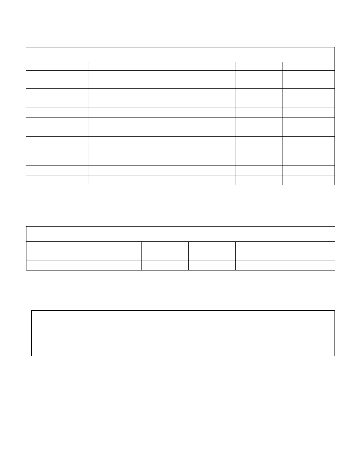
FRYER SPECIFICATIONS
GENERAL SPECIFICATIONS
PLAIN STEEL TANK
STAINLESS STEEL
Width
Overall Depth
Working Height
Overall Height
Fat Capacity (min.)
Foam Area
Fry Area
Basket Size
Shipping Weight
Shipping Cube
Gas Connection
FMP 403 HP-CE FMP 40-CE FMP 65-CE FMP 40 HP-CE FMP 65 HP-CE
FMS 403 HP-CE FMS 40-CE FMS 65-CE FMS 40 HP-CE FMS 65 HP-CE
15 ½ ‘’ 15 ½ ‘’ 20’’ 15 ½ ‘’ 15 ½ ‘’
30 ⅞ ‘’ 30 ⅞ ‘’ 36 ⅞ ‘’ 30 ⅞ ‘’ 37 ⅞ ‘’
34 ½” 34 ½” 34 ½” 34 ½” 34 ½”
46 ¾” 46 ¾” 46 ¾” 46 ¾” 46 ¾”
49 lbs. 43 lbs. 79 lbs. 56 lbs. 95 lbs.
13 ¾” x 22’’ 13 ¾” x 22’’ 18 ¼” x 28’’ 13 ¾” x 22’’ 18 ¼” x 28’’
13 ¼” x 15’’ 13 ¼” x 15’’ 18 ¼” x 19’’ 13 ¼” x 15’’ 18 ¼” x 19’’
12 ⅛’’ x 6 ½” x 5 12 ⅛’’ x 6 ½” x 5 17’’ x 8 ½’’ x 5 ¾’’ 12 ⅛’’ x 6 ½” x 5 17’’ x 8 ½’’ x 5 ¾’’
145 lbs. 155 lbs. 205 lbs. 165 lbs. 215 lbs.
14 cu. ft. 14 cu. ft. 21 cu. ft. 14 cu. ft. 21 cu. ft.
½’’ IPS ½” IPS ½” IPS ½” IPS ½” IPS
GAS SPECIFICATIONS
BTU/HR. INPUT
NATURAL GAS
PROPANE (LP) GAS
This fryer is intended for other than household use. Design certified for use on combustible
floor. Clearance for combustible construction is 6 inches from side, 6 inches from back.
110,000 115,000 135,000 135,000 160,000
4.0’’ WC 3.5’’ WC 3.5’’ WC 3.5’’ WC 3.5’’ WC
10’’ WC 10’’ WC 10’’ WC 10’’ WC 10’’ WC
3
Page 4

SECTION A – INSTALLATION AND OPERATING INSTRUCTIONS
A1 – Unpacking – With the container upright cut the plastic straps around shipping container and lift off top, exposing
Fryer. Check Fryer for any visible change due to exceptionally rough handling during shipping. Report damage to
the delivering Freight Carrier within 15 days of delivery.
A2 – Accessories shipped in the vessel include:
1 – Basket Hanger 1 – Tank Cover
2 – Baskets 1 – Large Basket
1 – Drain Pipe Extension 4 – Swivel Casters (2w/Locks)
4 – 6 inch Adjustable Legs 1 – Quick Disconnect Connector, 48’’ w/restraint
A3 - Mounting of Legs or Casters
of Fryer. When installing casters make sure the swivel lock casters are mounted towards the front of the fryer. A high
strength Restrainer and Quick Disconnect Gas Connecter must be installed when casters are used. Avoid putting
any strain on rear legs or casters when tipping fryer back to an upright position.
A4 – Pre-Installation Instructions
and Local codes, the National Fuel Gas Code, ANSI Z223.1 • NFPA54, and the Natural Gas and Propane Installation Code, CSA-B149.1, as
applicable.
A5 – Air Supply and Ventilation
properly and efficiently. The area in front of and above the Fryer must be clear to avoid any obstruction of flow of
combustion and ventilation air. Do not,
system or place the flue outlet directly into the plenum of the exhaust hood as it will adversely affect the gas
combustion of the Fryer.
The vent system should be of such design as to allow easy access for cleaning and degreasing on a regular basis in
order to prevent fires. An automatic fire extinguishing system should be an integral part of the vent design. Since the
temperature of the flue gases emanating from the Fryer flue can reach 1200° F, temperature sensing devices of the
automatic fire extinguishing system must be sized accordingly to prevent premature turn-on. The minimum vertical
distance from the top of the Fryer flue to vent system filters should be 18 inches or more.
A6 – Clearances
and non-combustible construction is as follows: 6 inches from SIDE and 6 inches from BACK. Fryer must be
installed with 6 inches high legs or casters (optional). At least 16 inches clearance must be provided between the
frying surface of the Fryer and the surface flames from any adjacent cooking equipment.
A7 – Gas Connection
that the gas type called for on label coincides with the type of gas available on site. A ½ inch NPT gas pipe
connection is provided at the rear of fryer. An accessible manual shut-off valve must be installed in the gas supply
line ahead of the Fryer for future service. The supply pipe must be sized to accommodate all the gas fired equipment
that may be connected to the gas supply. Check with your local Gas Company as to proper pipe size. Only pipe
sealant resistant to action of L.P. gas should be used on pipe joints. Before attempting to light Fryer, check joints for
tightness using a soap and water solution. Do not use an open flame.
A8 – Flexible Gas Connectors and Restraints
Connector that complies with the Standard for – Connectors for Movable Gas Appliances ANSI Z21.69 • CSA6.16 and a Quick-Disconnect
Device compliant with the Standard for Quick-Disconnect Devices for use with Gas Fuel Connector or Quick-Disconnect Device. A high
strength Restrainer and proper size Quick-Disconnect Gas Connector conforming to above ANSI and/or CAN/CGA standards should be
ordered from Cecilware in conjunction with our NSF approved casters. If disconnection of the restraint is necessary for servicing Fryer, the
– Your Fryer is design certified for use on combustible floors. The minimum clearances for combustible
– Before connecting Fryer to gas line, check the rating label on inside of door panel to make sure
– Carefully tip Fryer back and screw legs or (optional) casters into the threaded base
– The installation of your Fryer must be made by a licensed plumber and the installation must conform to State
– Adequate ventilation and air supply must be provided in order for the Fryer to operate
Accessories available as optional:
under any circumstances, connect the Fryer flue directly to a building exhaust
(See illustration 1) – For Fryers equipped with casters, installation shall be made with a
4
Page 5
Restraint must be reconnected after appliance has been returned to its originally installed position.
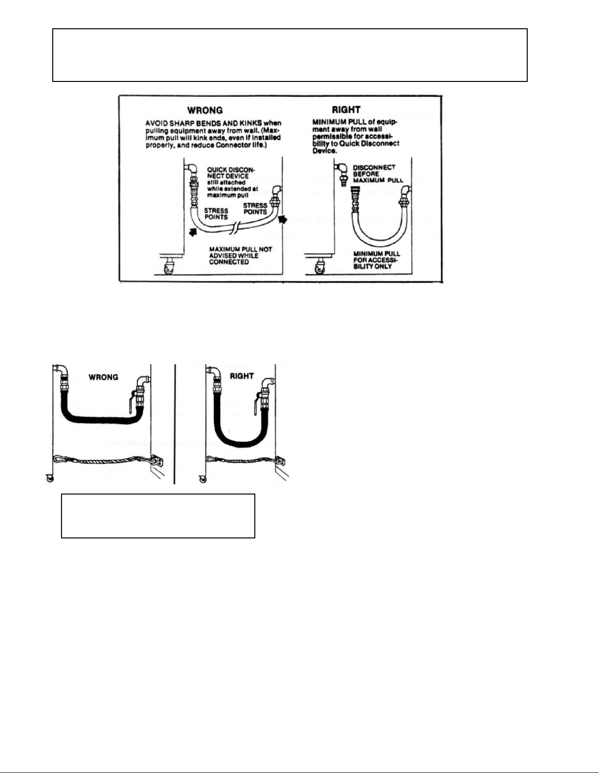
ILLUSTRATION 1
Installation of Quick Disconnect and High Strength Restrainer.
Set the length of the restraining device so that
the connector is not kinked when the
restraining device is fully extended.
Instructions for an appliance equipped with Casters:
1) The installation shall be made with a connector that complies with the Standard for Connectors for Movable
Gas Appliances, ANSI Z21.69 • CSA 6.16, and a Quick-Disconnect Device that complies to the Standard for
Quick-Disconnect Devices for use with Gas Fuel, ANSI Z21.41 • CSA 6.9.
2) Adequate means must be provided to limit the movement of the appliance without depending on the connector
and the Quick-Disconnect Device or its associated piping.
3) The location(s) where the restraining means may be attached to the appliance shall be specified.
1. Restraining device should be installed parallel (in line) with the gas
appliance connector.
2. Attach the staple bracket (C) to a stud in the wall using the four 1” #12
screws (D) and the plastic anchors (E), if needed.
3. Locate a structural area (frame) on the rear side of the equipment that is in
line with the wall attachment. Drill a small hole, ¼” (per manufacturers’
recommendation). Please use caution when drilling hole, so that internal
components are not damaged.
4. Slide the hex nut (G) and a washer (I) onto the eye-bolt (F). Slide the eyebolt through the opening and place a washer (I) and the nylon lock nut (H)
onto the eye-bolt on the inside frame of the equipment and tighten down.
5. Attach one of the spring-loaded hooks (B) to the mounted bracket on the
wall (Step 2) and the other to the eye-bolt (Steps 3 and 4).
Note: For adjustable restraining devices, the cable is manufactured to be
shorter than the length of the gas connector.
5
Page 6

USER INSTRUCTIONS
IMPORTANT – DO NOT ATTEMPT TO LIGHT OR OPERATE FRYER WITHOUT THE PROPER LEVEL OF FRYING
FAT (OR WATER) IN TANK, AS SERIOUS DAMAGE WILL RESULT. THIS APPLIANCE IS FOR
PROFESSIONAL USE BY QUALIFIED PEOPLE ONLY.
SECTION B – START UP PROCEDURE
B1 – Getting Ready to Use Fryer – Make sure that all steps in Section A are complete. Verify that gas is available to
Fryer.
B2 – Filling and Draining of Fryer Tank
water to the oil level line (hot or cold water can be used). When draining tank, allow hot contents to cool to safe
handling temperature.
B3 – Start-up Lighting and Operating Instructions:
1. Turn red Thermostat Knob D counter-clockwise to its lowest or off position.
2. Partially depress and turn Control Gas Cock Dial A to “OFF” position.
3. Wait five (5) minutes to allow gas which may have accumulated in the main burner compartment to escape.
4. Turn Gas Cock Dial A to ‘PILOT” position.
5. Depress Gas Cock Dial A and light Pilot C. Hold in depressed position for approximately 30 seconds, or until Pilot remains lit when Dial
is released.
Sufficient time must be allowed for a proper sized flame to heat the pilot thermocouple that holds the safety magnet in a locked-up
NOTE:
position. Also, time must be allowed for air to escape from the lines during the first operation.
6. Release Dial and turn to full “ON.”
Steps 7 – 13 help check burner operation, initial thermostat calibration and clean the vessel.
NOTE:
7. To operate main burners, rotate Red Thermostat Knob clockwise to 225° F or just above the boiling point of water.
IMPORTANT:
WITHOUT THE PROPER LEVEL OF LIQUID (OIL OR WATER) IN VESSEL OR SERIOUS DAMAGE WILL RESULT AND
CONSEQUENTLY VOID THE WARRANTY.
8. When water comes to a boil, turn Red Thermostat Knob back to 200° F. The burners should turn off.
9. If pilot becomes extinguished repeat above procedure.
10. For stand-by periods, turn Gas Cock Dial A to “PILOT” position.
11. To shut Fryer down, partially depress and turn Gas Cock Dial A to “OFF” position and turn Thermostat to its lowest of off position.
12. Drain the vessel by means of the drain valve and Extension Pipe provided. Use caution when draining hot vessel.
13. Remove Extension Pipe. Wipe away any remaining water from the vessel and drain. Close Drain Valve and proceed to “Normal Daily
Operation.” If the latter is not convenient at this time, apply a protective coating of salt-free shortening to vessel surfaces. (Applies to
Cold Rolled Steel Tanks only).
DO NOT TURN ON MAIN BURNERS UNLESS FILLING INSTRUCTIONS WERE COMPLETED. NEVER OPERATE FRYER
– Close Drain Valve (red handle in horizontal position) and fill it initially with
(See Illustration 2)
6
Page 7

SECTION C – NORMAL DAILY OPERATION
‘
Follow this procedure after the Fryer has already been started up for the first time or after Fryer has been shut down for maintenance.
C1 – Filling the Vessel for Frying
shortening is pre-melted; if not, shortening must be packed tightly around the Heat Transfer Tubes before any attempts are made to turn on
Fryer. NEVER attempt to melt a solid block of shortening by setting it on top of the Heat Tubes. Loosely packed solid shortening will create
air voids around Heat Transfer Tubes of Fryer. When fired up, tubes will become red hot and will cause shortening to scorch and burn
creating a fire hazard. The safest way to melt solid shortening gradually is by turning burners “ON” for 5 seconds and then “OFF” for 15
seconds. This procedure is to be repeated until the tubes are covered with melted shortening. If any smoke is noticed during this melt cycle
procedure, reduce the burner “ON CYCLE.” Replace Crumb Screen over tubes when melted shortening has reached the “OIL LEVEL” line.
C2 – Lighting Instructions
C3 – Fryer Operation
minutes). The Burners are thermostatically controlled and will cycle on and off to maintain correct frying temperature. The “Safety Pilot” will
remain lit until the gas is shut off.
C4 – Special Hi-Limit Safety Control
down the Burners should operating temperatures exceed 460°F (due to operating thermostat out of calibration or low oil level in tank). To
reset Hi-Limit Control, wait 30 minutes to allow fat to cool down, or add additional cool oil or shortening for faster response, then push the
Red Pin E on Hi-Limit Control and relight pilot following steps (1) through (8) in Section B3.
C5 – Shut-Down and Draining
position. To shut Fryer down completely, partially depress and turn Gas Cock Dial to “OFF” position. When draining tank, allow shortening to
cool to a safe handling temperature.
– Set the Thermostat Knob to desired frying temperature and allow shortening to pre-heat (75° F to 350° F in 7
– Close Drain Valve and fill to proper level (Oil Level) with frying fat. If solid shortening is used, be certain
– Follow instructions on data label attached to inside Door Panel or as outlined in Section B3 of this manual.
– Your Fryer is equipped with an over-temperature or Hi-Limit Control that will trip and automatically shut
– For temporary shut down, turn thermostat to lowest or off position. Then turn Gas Cock Dial to “PILOT”
7
Page 8

SECTION D – MAINTENANCE
D1 - Daily:
1) Shut down Fryer as per Section C5. Drain completely (using Drain Pipe Extension) into clean suitable container or filter pump.
2) Detach Basket Hanger Bracket, remove screen and wipe clean with cloth.
3) Flush out any remaining sediment in tank using some hot oil. Wipe off and clean fry kettle.
4) Close Drain Valve and strain shortening back into fryer using several layers of cheese cloth or filter through an oil pump equipped
with a Micro-Flo filtering system. Replace Crumb Screen and Basket Hanger Bracket. Detach Drain Nipple. Fryer is ready for next
operation.
D2 – Weekly:
compound and hot water. Drain and rinse thoroughly. Wipe dry with clean cloth. Clean exterior stainless steel surfaces of body with
stainless steel cleaner. Do not use abrasive cleaners or steel wool.
D3 – Periodic Checks:
observe reading when burner goes out. Compare the reading. If the temperatures do not coincide within 5°F, have a qualified service
person calibrate the thermostat. See Adjustment Procedure, Section E, below. Clean unit and dirt off air shutters and main burners.
Periodically, (approximately once a year), burners an pilot should be cleaned to maintain proper ignition and burner flame efficiency.
D4 – Outside Service:
Repeat daily maintenance procedure to point (4). Close Drain Valve and clean vessel thoroughly with a deep fat fryer cleaning
Temperature of frying compound. Set Thermostat Knob to 350°F. Place a fryer thermometer in fat (1 ½ inches) and
Should you require help, contact the factory, your factory representative, or your local service company.
8
Page 9

Replacement Parts List
ITEM
1 FRONT FASCIA ASSEMBLY U558Q U558Q U621Q U558Q U621Q
2 FLAME SHIELD (2 TUBES) T997A T776A T776A T997A T997A
FLAME SHIELD (1 TUBE) T998A – T777A T998A T998A
*3 FRY TANK TA44A T475A T641A TA53A TA55A
4 BURNER MANIFOLD F010A F009A F011A F009A F011A
5 THERMOSTAT BRACKET U572V U572V U572V U572V U572V
6 HI-LIMIT CONTROL L346A L346A L346A L346A L346A
7 THERMOSTAT L345A L345A L345A L345A L345A
8 THERMOSTAT HARNESS C946Q C946Q C946Q C946Q C946Q
9 GAS CONTROL VALVE (NAT) L715A L715A L715A L715A L715A
GAS CONTROL VALVE (LP) L718A L718A L718A L718A L718A
10 BRASS PLUG K044A K044A K044A K044A K044A
11 * ½” GAS INLET PIPE J053A J053A J065A J063A J065A
12 AIR SHUTTER CLAMP U574A U574A U574A U574A U574A
13 AIR BURNER SHUTTER F167A F167A F167A F167A F167A
14 GAS BURNER G363A G224A G224A G363A G363A
15 DRAIN VALVE D098A D098A D098A D098A D098A
16 MAGNETIC CATCH U008A U008A U008A U008A U008A
17 PILOT ASSEMBLY (NAT) F261A F261A F261A F261A F261A
PILOT ASSEMBLY (LP), 0.018” F262A F262A F262A F262A F262A
18 THERMOPILE TP-75, 0.010” F178A F178A F178A F178A F178A
19 DRAIN PIPE J062A J062A J062A J062A J062A
20 BAFFLE UB71Q UB34Q UB64Q UB77Q UB72Q
21 FLUE BOX ASSEMBLY T994Q T894Q T655Q T994Q TA41Q
22 BASKET SUPPORT BRACKET T536A T536A T644A T536A T644A
23 BASKET HANGER FASTENER P281A P281A P281A P281A P281A
24 FRY BASKET V174A V174A V180A V174A V180A
25 CRUMB SCREEN V172A V172A V179A V172A V179A
26 LEGS M219A M219A M219A M219A M219A
27 SWIVEL CASTER (OPTIONAL) M014A M014A M014A M014A M014A
28 SWIVEL CASTER W/LOCK (OPT.) M015A M015A M015A M015A M015A
29 FRY BASKET, LARGE (OPT.) V175A V175A – V175A –
30 BULB CLAMP U567A U567A U567A U567A U567A
31 GAS ORIFICE, NAT (BRASS) F268A F270A F270A F268A F268A
GAS ORIFICE, LP (BRASS) F271A F272A F272A F271A F264A
32 FRY TANK COVER U589Q U589Q U641Q U589Q U641Q
33 FRONT DOOR ASSEMBLY T534Q T534Q T657Q T534Q T657Q
34 BURNER SUPPORT ASSEMBLY T632Q T541Q T646Q TA52Q T645Q
35 THERMOSTAT KNOB M099A M099A M099A M099A M099A
36 5” HI-LIMIT WIRE ASSEMBLY C945Q C945Q C945Q C945Q C945Q
37 ¾” F x ¾” UNION ELBOW K158A K158A K158A K158A K158A
38 ½” F x ½” UNION ELBOW K204A K204A K204A K204A K204A
39 DOOR HINGE U579A U579A U579A U579A U579A
40 CASEBACK T537A T537A T67A T537A TA49A
41 THERMOSTAT LABEL NK52A NK52A NK52A NK52A NK52A
42 BANKING STRIP U631A U631A U633A U631A U633A
GAS CONNECT KIT (48”/122 cm),
43
WITH RESTRAINING DEVICE
*FMP 403HP (CRS TANK) USE P/N TA43A
*FMP 40 USE P/N T531A
*FMP 65 USE P/N T638A
*FMP 40HP-CE USE P/N TA52A
*FMP 65HP-CE USE P/N TA54A
DESCRIPTION
FMS 403HP-CE
FMP 403HP-CE
UB75A UB75A UB75A UB75A UB75A
FMS 40-CE
FMP 40-CE
FMS 65-CE
FMP 65-CE
FMS 40HP-CE
FMP 40HP-CE
FMS 65HP-CE
FMP 65HP-CE
9
Page 10

Illustration 3
Deep Fat Fryer
10
Page 11

FM 403HP
Shown
11
Page 12

FM 65
Shown
12
Page 13

13
Page 14

14
Page 15

ACCESSORIES FOR GAS FRYER
15
Page 16

SECTION E – ADJUSTMENTS “FOR QUALIFIED SERVICE PERSONNEL ONLY”
NOTE: Only for qualified service personnel specializing in Hotel and Restaurant Cooking Equipment. Factory approval required prior to any
warranty repairs.
E1 – Safety Pilot:
and leak test with Soap Solution. Tighten cap is necessary.
E2 – Burners:
side of Venturi and rotate air shutter until flame with soft blue inner cone is achieved. Remove any lint accumulated, if necessary.
E3 – Thermostat Calibration:
screw driver (⅛ inch) into hollow thermostat shaft and engage center adjustment screw. When thermometer reading approached 375°F,
slowly turn the adjustment screw clockwise until burners go out. Turning the screw counter-clockwise will increase the temperature.
: One quarter turn will change temperature setting approximately 25°F. Replace knob and check temperature through 3 cycles. Repeat
NOTE
adjustments if necessary until knob setting is correct within a few degrees.
Remove Pilot Adjustment Cap (B) and turn Adjustment Screw to provide properly sized flame (¾ inch long). Replace Cap
Burners are factory set for maximum performance. Should further adjustment be required, loosen the Slotten Hex Screw on
Turn the Thermostat Knob to 375°F and remove knob without moving thermostat shaft. Place narrow bladed
TROUBLESHOOTING GUIDE – For Qualified Service Persons Only
E4 – Troubleshooting Guide
Problems Cause Remedies
A. Pilot will ignite but will not remain
alight when Gas Cock Dial is released.
B. Main Burners will not fire with supply
gas valve open and incoming gas
present.
C. Main Burners and Safety Pilot go out
after fryer has reached operating
temperature.
D. Main Burners do not come up to full
power, flames appear to be lazy. Takes
too long to reach operating temperatures.
E. Frying temperature too high –
shortening scorches and discolors
quickly.
1) Loose electrical connection at Hi-Limit
Switch, Gas Control Valve or Thermostat.
2) Pilot flame too low.
3) Dirt in pilot.
4) Excessive draft caused by exhaust, air
conditioner or make-up air equipment.
5) Thermopile defective.
1) Loose connections at Thermostat
Switch or Gas Control Valve.
2) Defective Thermostat Switch, Gas
Control Valve or GS-7 Hemostat.
1) Hi-Limit Safety Switch cut out due to
out of calibration Thermostat.
1) Gas pressure drop.
2) Defective or incorrect Gas Control
Valve.
1) Thermostat set too high.
2) Shortening contaminated or of low
quality.
1) Retighten connections (see
illustrations 2 and 2a).
2) Relight and adjust (as per instructions
in Section E).
3) Remove pilot burner orifice, blow out
dirt, replace, and relight pilot burner.
4) Reduce draft by regulating or diverting
air flow.
5) Replace Thermopile.
1) Retighten connections (see
illustrations 2 and 2a).
2) Replace in that order.
1) Recalibrate Thermostat as per
instructions in Section E3. If temperature
is OK replace Hi-Limit Switch and light
pilot.
1) Check gas manifold pressure by
removing ⅛” NPT Plug and measuring
pressure using U-Gauge Manometer.
With Burners on, pressure should read
3.5’’ WC for NAT and 10.0’’ WC for
PROP gas. Check Supply Line sizing.
See Section A, “Gas Connection.”
2) Replace Gas Control Valve (see
Illustration 2 and 2a).
1) Check temperature of shortening and
adjust thermostat (as per instructions in
Section E).
2) Filter or strain shortening. Use higher
grade shortening.
16
 Loading...