

Page 1
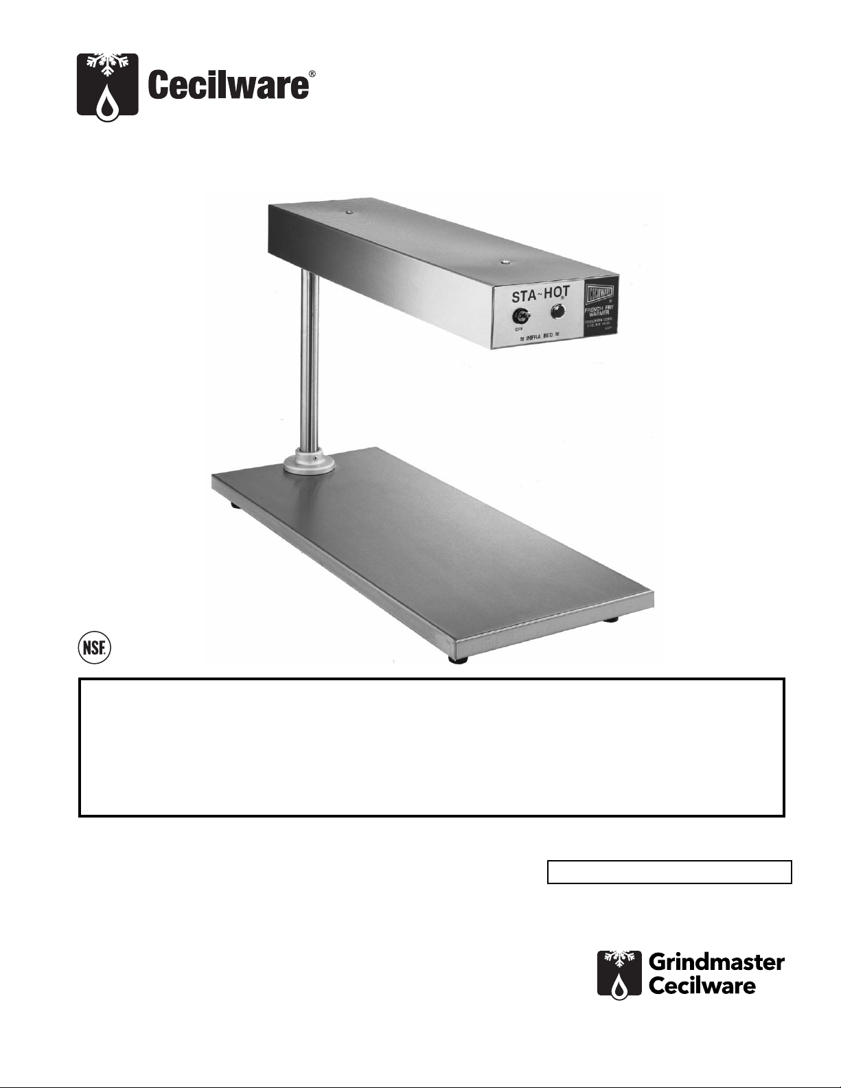
French Fry Warmer
Operator Manual
FFW575M, FFW575Q
Grindmaster-Cecilware
4003 Collins Lane, Louisville, KY 40245 USA
Phone: 502.425.4776 Toll Free: 800.695.4500
Fax: 502.425.4664
Web: gmcw.com Email: info@gmcw.com
Safety Information .....................................2
Unpacking...................................................3
Installation..................................................3
Cleaning......................................................3
Maintenance...............................................3
Parts Diagram and List ...............................4
Thank you for purchasing this quality Warmer. For your safety and the safety of others, read all warnings
and the operator’s manual before installing or using the product. Properly instruct all operators. Keep
training records. For future reference, record serial number here:
Table of Contents
©2016 Grindmaster-Cecilware
Printed in USA
0916 Form # CW-340-01
Part # 390-00085
Grindmaster-Cecilware provides the
industry’s BEST warranty. Visit gmcw.com
for warranty terms and conditions.
Model: FFW575
Page 2
2 Cecilware
®
French Fry Warmer
Safety Information
Important Safety Information
This is the safety alert symbol. It is used to alert you to potential personal injury hazards. Obey all safety messages
that follow this symbol to avoid possible injury or death.
WARNING
• Do not deform power cord.
• Follow national and local electrical codes.
• Do not store or use gasoline or other flammable vapors and liquids in the vicinity of this or any other
appliance.
• Use only on a dedicated circuit load that is properly protected and capable of the rated load. Do not use
extension cords, as this could result in electrical shock, overheating, and fire.
• Risk of electrical shock. Disconnect power before servicing or cleaning unit. Contact Grindmaster-Cecilware
Technical Service for service assistance.
• If the supply cord is damaged, it must be replaced by the manufacturer, its service agents, or similarly
qualified persons in order to avoid a hazard.
• Due to the heat a warmer may produce, it must be placed with at least 1 inch clearance from all surfaces
at side and rear.
FAILURE TO COMPLY TO THE ABOVE RISKS PERSONAL INJURY, SHOCK HAZARD, FIRE, OR DAMAGE TO
EQUIPMENT.
CAUTION
• Read and understand the operating instructions in this manual thoroughly. Only allow properly trained
persons to operate this machine.
• Stay alert at all times during operation.
• Operate with care. Surfaces will get very hot and may cause serious burns.
NOTICE
• Keep operating area clean.
For your safety and the safety of others, read all warnings and the operator’s manual before installing or using
the product.
DANGER: This term warns the user of imminent hazard that will result in serious injury or death.
WARNING: This term refers to a potential hazard or unsafe practice, which could result in serious injury or
death.
CAUTION: This term refers to a potential hazard or unsafe practice, which could result in minor or moderate
injury.
NOTICE: This term refers to information that needs special attention or must be fully understood.
Page 3

French Fry Warmer Cecilware
®
3
Unpacking
Carefully lift unit out of shipping container, and inspect
immediately for shipping damage. Your French Fry
Warmer was shipped in a carton designed to give it
maximum protection. It was thoroughly inspected
before leaving the factory. File any claims for shipping
damage or irregularities directly with the carrier.
Installation
Distance required between combustible and noncombustible material: 1” rear and 1” sides.
The FFW575-Q and M are supplied with an attached
cord and may be plugged into a standard 120 volt 15
amp/ grounded outlet. This unit has been shipped with
the incandescent lamps installed. Remove the protective
cardboard tube from lamps before turning the warmer
on.
Cleaning
Stainless steel exterior surfaces can be cleaned with a
damp cloth.
Maintenance
Lamp Replacement:
Simply unscrew lamp from socket, discard defective
lamp and screw new lamp into socket.
Heating Element Replacement:
Place warmer on its side. Remove two screws from
access covers at the front and rear of the unit and
remove the covers. Remove flag terminals from heater
ends and remove heater. Push flag terminals on to ends
of new heater, making sure terminals are pushed on
securely, as a loose terminal will cause arcing. Position
the element in unit so that groove in porcelain end cap
is nested in notch of bracket. Hold the element in place
and replace one access cover, making sure that vertical
leg of access cover is between element holder and
reflector, secure with two screws. Install second access
cover in the same manner.
Switch Replacement:
Remove the front access cover. Remove nut securing
switch to the front of the housing and pull the switch
out from inside housing. Disconnect switch wires taking
note of their location. Reconnect wires to new switch
and re-install by reversing removal procedure.
If you need help, call Grindmaster-Cecilware Technical
Service Department, (502) 425-4776 or (800) 695-4500
(USA & Canada only) (Monday through Friday 8 AM - 6
PM EST). Please have the model and serial number
ready so that accurate information can be given.
Prior authorization must be obtained from
Grindmaster- Cecilware for all warranty claims.
Grindmaster-Cecilware provides the industry’s
BEST warranty. Visit our website at GMCW.com
for warranty terms and conditions.
CAUTION: To avoid burns, allow warmer to cool
before cleaning.
CAUTION: Disconnect power from warmer before
attempting electrical repairs.
Page 4

Grindmaster-Cecilware
4003 Collins Lane, Louisville, KY 40245 USA
Phone: 502.425.4776 Toll Free: 800.695.4500
Fax: 502.425.4664
Web: gmcw.com Email: info@gmcw.com
Grindmaster-Cecilware provides the
industry’s BEST warranty. Visit gmcw.com
for warranty terms and conditions.
©2016 Grindmaster-Cecilware
Printed in USA
0916 Form # CW-340-01
Part # 390-00085
Parts Diagram and List
ITEM DESCRIPTION PART #
1 TOGGLE SWITCH L232A
2 PILOT LIGHT C165AL
3 LAMP (120V) (2 REQ'D) V126A
4 LAMP SOCKET, DUAL B057A
5 HEATING ELEMENT (120V) QUARTZ G132A
5 HEATING ELEMENT (120V) METAL G189A
6 LEG (4 REQ'D) M363A
7 STRAIN RELIEF B076A
8 LINE CORD ASSEMBLY (120V) C032AL
1
2
3
4
5
6
 Loading...