

Page 1
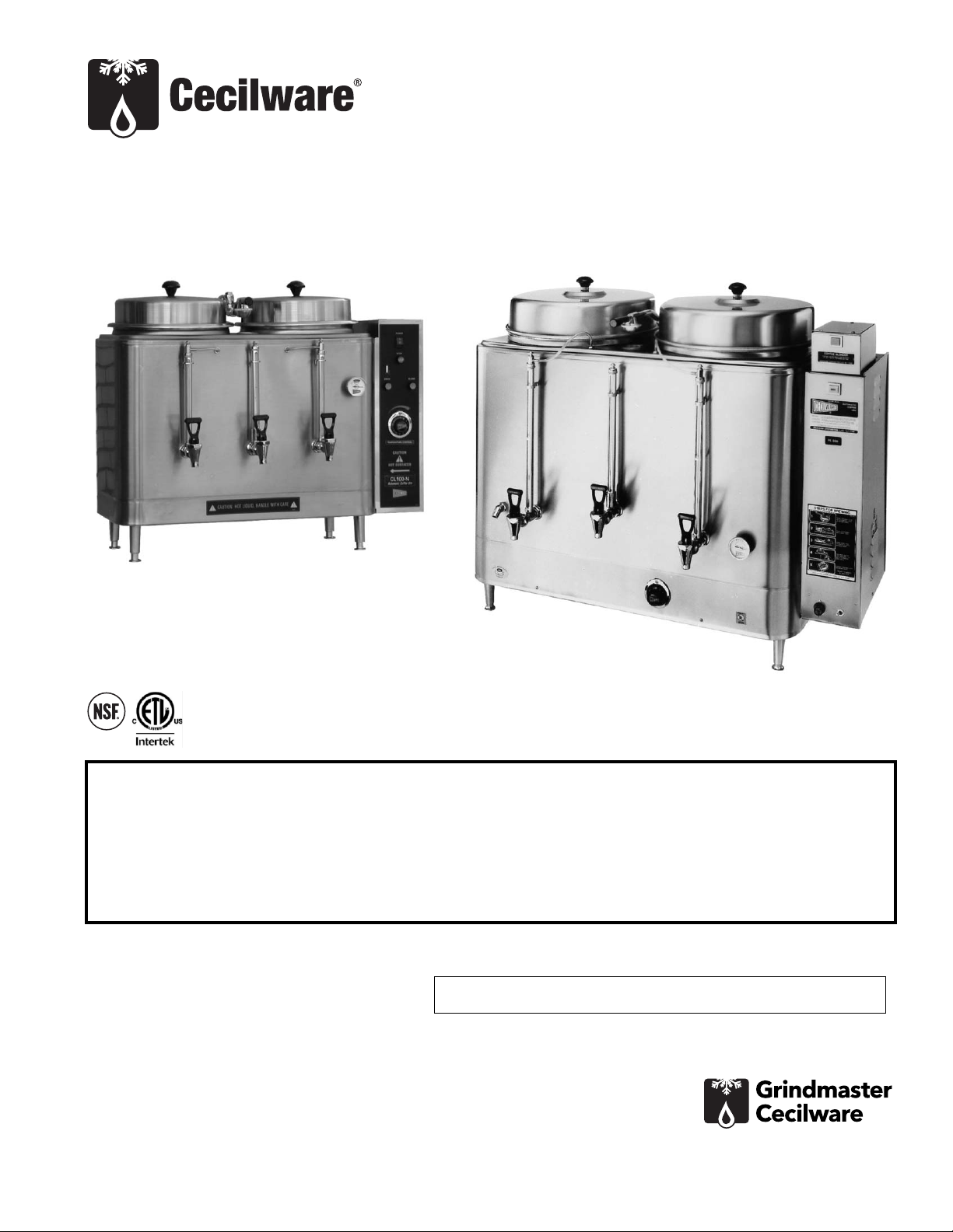
Coffee Urns
FE75N, FE100N, FE200, FE300,
CL75N, CL100N, CL200 Series
Operator Manual
Grindmaster-Cecilware
4003 Collins Lane, Louisville, KY 40245 USA
Phone: 502.425.4776 Toll Free: 800.695.4500
Fax: 502.425.4664
Web: gmcw.com Email: info@gmcw.com
Safety Information..................2
Rough-In Drawings .................3
Electrical Specifications...........5
Installation...............................5
Priming ....................................6
Operation ................................6
Cleaning...................................7
Adjustments ............................7
Maintenance ...........................9
Parts Diagram........................12
Parts List.................................15
Wiring Diagram.....................16
Thank you for purchasing this quality urn. For your safety and the safety of others, read all warnings and the
operator manual before installing or using the product. Properly instruct all operators. Keep training records. For
future reference, record serial number here:
Table of Contents
©2016 Grindmaster-Cecilware
Printed in USA
0516 Form # CW-326-01
Part # 390-00070
Grindmaster-Cecilware provides the
industry’s BEST warranty. Visit gmcw.com
for warranty terms and conditions.
Model FE300
Model CL100N
Page 2
GB Series Cecilware
®
2
For safe and proper operation, the appliance must be placed in a stable, vertical position.
To reduce risk of serious burns or scalding, do not place hand or other body parts under dispenser or container
while product is brewing.
Always unplug unit from power supply before servicing.
Hot liquid in brew basket could cause burns. Remove with care.
Surfaces are hot and can cause burns.
CAUTION
To reduce risk of electrical shock, do not remove or open cover. No user-serviceable parts inside. Repair should
be done by authorized service personnel only.
The appliance is not intended for outdoor use.
Do not clean with pressurized water or use in an area where pressurized water may be used.
Cleaning and maintenance shall be made only by properly trained persons with supervision.
This appliance is not intended for use by persons with reduced physical, sensory, or mental capabilities, or lack
of experience and knowledge, unless they have been given supervision or instruction concerning use of the
appliance by a person responsible for their safety.
Children should be supervised to ensure that they do not play with the appliance.
Do not alter or deform the power cord or plug in any way! Altering or deforming the plug may cause electrical
shock, damage unit and will void warranty.
To reduce risk of explosion or fire, do not use near combustibles.
WARNING
Safety Information
2 Cecilware
®
Coffee Urns
Important Safety Information
This is the safety alert symbol. It is used to alert you to potential personal injury hazards. Obey all safety messages
that follow this symbol to avoid possible injury or death.
For your safety and the safety of others, read all warnings and the operator manual before installing or using
the product.
DANGER: This term warns the user of imminent hazard that will result in serious injury or death.
WARNING: This term refers to a potential hazard or unsafe practice, which could result in serious injury or death.
CAUTION: This term refers to a potential hazard or unsafe practice, which could result in minor or moderate
injury.
NOTICE: This term refers to information that needs special attention or must be fully understood.
Use only on a circuit that is properly protected and capable of the rated load.
Electronically ground the chassis.
Follow national and local electrical codes.
Do not use extension cord.
This equipment must be installed in compliance with applicable Federal, State, and/or Local plumbing codes
having jurisdiction. This product requires an approved back flow prevention water device, such as a double
check valve, to be installed between the machine and the water supply.
NOTICE
Page 3
Coffee Urns Cecilware
®
3
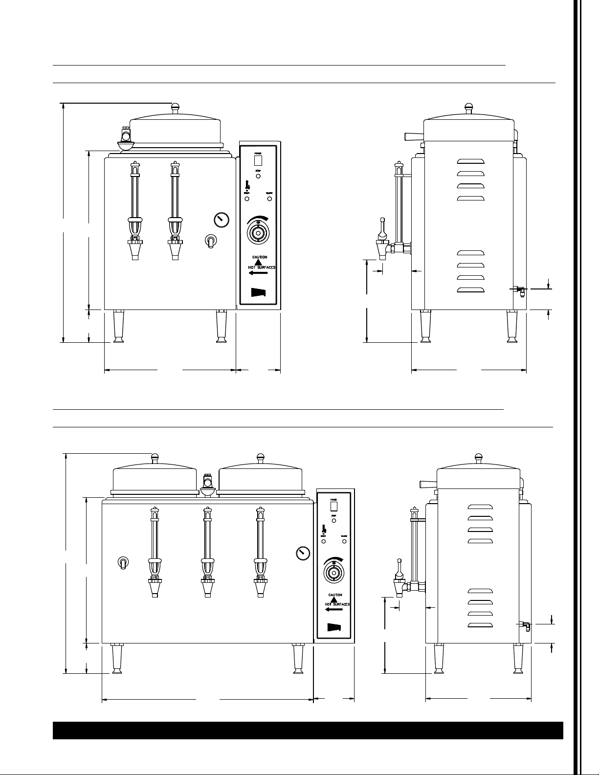
Rough-In Drawings
FE75N Single 3 Gallon Urn, Adjustable By-pass, Automatic Agitator, and Solid State Timer
CL75N Single 3 Gallon Urn, Adjustable By-pass, Push-Button Agitator, and Electro-Mechanical Timer
FE100N Twin 3 Gallon Urn, Adjustable By-pass, Automatic Agitator, and Solid State Timer
CL100N Twin 3 Gallon Urn, Adjustable By-pass, Push-Button Agitator, and Electro-Mechanical Timer
10
9
F
8
29.1
19.3
F
O
7
6
5
1
4
2
3
3.5
NN10A
10.1
2.5
4.0
14.016.0 5.4
29.1
19.3
10
9
F
8
F
O
7
6
5
1
4
2
3
4.0
28.0
5.4
3.5
NN10A
10.1
2.5
14.0
Page 4
4 Cecilware
®
Coffee Urns
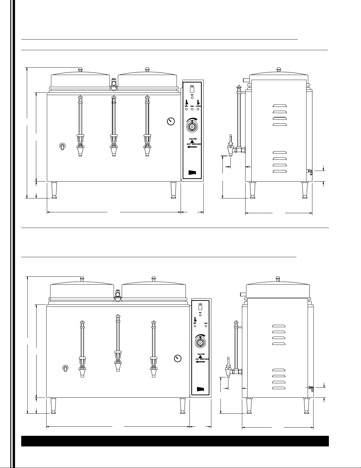
Rough-In Drawings (continued)
FE200N Single 6 Gallon Urn, Adjustable By-pass, Automatic Agitator, and Solid State Timer
CL200N Single 6 Gallon Urn, Adjustable By-pass, Push-Button Agitator, and Electro-Mechanical Timer
FE300N Twin 10 Gallon Urn, Adjustable By-pass, Automatic Agitator, and Solid State Timer
10
31.2
21.2
4.0
9
F
8
F
O
7
6
5
1
4
2
3
3.5
NN10A
10.1
2.5
32.0 5.4
16.0
10
9
F
8
F
O
34.5
23.4
7
6
5
1
4
2
3
4.0
36.1 5.4
NN10A
3.5
9.1
2.5
18.0
Page 5
Coffee Urns Cecilware
®
5
Installation
Unpacking Instructions
Carefully unpack the machine and inspect immediately
for shipping damage. The packaging may contain
unattached parts. Your machine was shipped in a carton
designed to give it maximum protection in normal
handling. It was thoroughly inspected before leaving
the factory. In case of damage, contact the shipper, not
Grindmaster-Cecilware.
NOTICE: The person installing this appliance is
responsible for ensuring that electric and water
connections meet the requirements of the national
electric code, national plumbing code, and any local
ordinances.
See Rough-in Drawings for approximate dimensions
and locations of electric and water input.
Mechanical Installation
NOTICE: Do not turn thermostat on until all
installation instructions have been followed.
1. Inspect unit to see if any damage occurred in
shipment.
2. Remove the urn from the packing material. The
four legs, faucets, and vent cap drain are packed
separately with urn.
3. Install legs by tilting urn on its side and screwing
legs into urn leg supports until hand tight.
4. Carefully right unit and install in its permanent
location, being sure to leave at least 6" on right side
of urn for access to controls. Position urn so that the
faucets drip into a drip trough or drain receptacle
of some type.
5. Level urn by adjusting legs. Then attach faucets and
install vent cap drain.
6. Cover(s) are shipped with knob(s) on inside to
prevent damage. Simply unscrew and reverse.
WARNING: ELECTRIC SHOCK HAZARD!
Installation of this appliance should be performed by
qualified service personnel only. Improper installation
could result in electrocution.
CAUTION
These urns are heavy pieces of equipment. It is
recommended that moving or lifting the unit be done
by two people to avoid injury.
MODEL VOLTS KILOWATTS AMPS
1 PHASE 3 PHASE 1 PHASE 3 PHASE
3 WIRE 4 WIRE
FE75N, CL75N
120/240
7
6
29
15
120/208 5.3 4.5 26 12
FE100N 120/240 6 8 34 20
120/208 8 6 29 17
CL100N 120/240 7 8 29 20
120/208 5.3 6 26 17
FE200N, CL200N 120/240 10 10 42 24
120/208 7.5 7.5 38 22
FE300N
120/240
-
15
-
37
120/208
-
11.3
-
33
MODEL WIRE SIZE
1 PHASE 3 PHASE
FE75N, CL75N, CL100N (2) 10 AWG + GND
(3) 10 AWG + GND
FE100-N (2) 8 AWG + GND (3) 8 AWG + GND
FE200-N, CL200-N (2) 6 AWG + GND (3) 8 AWG + GND
FE300-N - (3) 10 AWG + GND
Neutral and Ground Wires # 14 AWG min.
Note: Field wiring must be suitable for 75° C. Use copper wire only for power supply connections.
GROUNDING: ON ALL URNS, CONNECT A GROUND WIRE TO GROUNDING LUG TO COMPLY WITH LOCAL
ELECTRICAL CODES (14 AWG MIN. 75° C)
Recommended Wire Size For Field-Wiring Urns US models only. Consult factory for export model information..
Electrical Specifications
Information below provided for US models only. Check rating marking on urn nameplate. Consult factory for
export model information.
Page 6
6 Cecilware
®
Coffee Urns
Water Hook-up
NOTICE:
This equipment must be installed in
compliance with applicable Federal, State, and/or Local
plumbing codes having jurisdiction. This product requires
an approved back flow prevention water device, such as
a double check valve, to be installed between the
machine and the water supply. Incoming pressure should
be greater than 30 psi and not more than 70 psi.
Urn should be connected to cold water supply
1. The automatic coffee urn is equipped with a ¼"
Flare water inlet fitting which is located on the back
of the unit.
2. Provide shut-off valve and union in supply line near
urn.
3. Minimum inlet pressure at urn should be 30 PSI.
4. Maximum inlet pressure recommended at 70 PSI.
5. Copper flex tubing should be used for valve
connections.
6. To ensure pressure at the urn of at least 30 PSI, use
3/8" OD tubing for short runs, 1/2" OD tubing for
longer runs, and larger size tubing for unusually
long runs. Be sure other appliances will not reduce
water pressure excessively.
7. Turn on the water supply line and check for leaks.
NOTE: For the best tasting coffee, add a filtering system
to the water supply line to eliminate any taste and/or
odor from the water.
NOTE: In areas with extremely hard water, a water
softener must be installed in order to prevent mineral
deposits that could result in malfunctioning of the
equipment and in order not to void the warranty.
Electrical Hook-up
NOTICE: This equipment must be installed in compliance
with applicable Federal, State and/or Local electrical codes
having jurisdiction. Do not use extension cords. Make sure
that the outlet the urn plugs into is grounded.
1. Check rating marking on urn nameplate to be sure
electric lines match voltage, phase, and amperage
requirements of urn. Select the proper cord and
cord grip for electrical rating of the urn.
2. Urn body MUST be grounded. A grounding
terminal is provided for this purpose.
3. Use only copper wire to connect this urn.
NOTE: THERMOSTAT MUST BE IN THE "OFF" POSITION.
1. Open water supply line valve to urn.
2. Turn on or plug in the power supply to the urn.
Water compartment will begin to fill automatically.
Do not power up the urn when the water line is off.
3. Wait until water is visible in center gauge glass (lefthand gauge glass on 3-gallon single urns). Then
turn thermostat knob to 10; thermostat pilot light
shows heater is on. Urn jacket will continue to fill
automatically until water reaches the proper level.
4. When indicator on dial thermometer approaches
the "W" in BREW zone, 195°F (92°C), urn is ready to
brew coffee.
5. In high altitude locations (over 5000 ft. above sea
level), thermostat may have to be lowered to
prevent boiling.
6. Brew and discard at least one batch of water into
each liner. Check that the fill level is correct. See the
Adjustments section if changes are needed.
Operation
1. Place filter paper in brew basket with designated
amount of coffee grounds. Coffee experts
recommend from 6 to 10 ounces of coffee per gallon
of water. Use fresh urn grind or drip grind coffee
spread evenly on filter for proper extraction. Make
certain you have a level bed of coffee. Consult your
coffee supplier for exact brewing specifications.
2. Water should be heated to 195°F (92°C) before
brewing coffee.
3. While brewing, leave cover on urn to preserve
aroma and prevent excessive steaming. Total contact
time for urn grind should be approximately 4-6
minutes. When the brew is finished, allow one to
two minutes for the coffee to drip from the basket.
4. When the drip period is complete, center the spray
arm and remove the basket to throw away the
grounds. Replace the liner cover to keep the coffee
hot. Never pour coffee back through spent grounds.
• Urns with automatic agitator (FE series), blend
coffee automatically at end of brewing cycle.
Press and hold agitator BLEND switch for
additional blending.
• If urn has a manual agitator (CL series), press
and hold agitator BLEND switch for 20 seconds
after brewing cycle to blend coffee.
5. Coffee is ready to serve.
6. Hold coffee at 185°-190°F (85°-88°C) (about 8 on
thermostat). Brewed coffee should not be held for
longer than one (1) hour and should never be
reheated.
WARNING: ELECTRIC SHOCK HAZARD!
Installation of this appliance should be performed by
qualified service personnel only. Improper installation
could result in electrocution.
Installation (continued) Priming
WARNING: ELECTROCUTION HAZARD!
Never use the ground conductor as a neutral. This
could cause electrocution.
CAUTION: BURN HAZARD
Water used for brewing coffee is very hot. Use
caution when brewing, pouring, or transporting
coffee. Accidental spills may result in severe burns.
Use caution when disposing grounds.
Page 7

Coffee Urns Cecilware
®
7
NOTICE: All sanitizing agents in the food zone must
comply with 21 CFR 178.1010. Sanitize all food
dispensing units periodically. All parts to be sanitized
must be cleaned first. Cleaning and sanitizing frequency
must follow state and local health department
regulations.
NOTICE: Do not use cleansers, bleach liquids,
powders, or any other substance containing chlorine.
These products promote corrosion and will pit the
stainless steel. USE OF THESE PRODUCTS WILL VOID THE
WARRANTY.
After Each Brew:
1. Dispose of grounds and rinse brew basket.
Every Day:
1. Drain the urn; then run a brew cycle of hot water.
After spraying hot water into the liner, thoroughly
brush the liner with a long handled brush.
2. Drain the water and repeat step one. Run another
brew cycle. Brush the liner and drain.
3. Wash the wire brew baskets with urn cleaner and
rinse thoroughly.
Weekly or Bi-Weekly, Depending on Use:
1. Fill the urn liners with several gallons of hot water.
2. Pour into the liner the recommended concentration
of urn cleaning compound. Set the thermostat to
high (NO. 10) and then run a brew cycle of hot
water.
3. Allow solution to remain in the liner for
approximately 30 minutes.
4. Scrub the inside of both the liner and the cover with
a long handled brush.
5. Drain the cleaning solution from the liner. Rinse by
running several brew cycles with the sprayhead
centered over the liner. Be sure to drain the rinse
water between cycles.
6. Thoroughly clean the faucets.
7. Use a long, thin gauge glass brush to clean the
coffee gauge glass. Use the same brush to clean the
fitting at the bottom of the liner and the pipe
connected to the coffee faucet.
8. Reassemble faucets. Fill the liners with hot water
and drain until the liner and all parts are completely
rinsed.
Adjustments
Thermostat Adjustment
The Thermostat is factory set for proper dispense
temperature of 200°F ± 3°F with the control knob set to
the maximum clockwise position. If field adjustments
are needed proceed as follows:
• To DECREASE temperature, turn the control knob
slightly in the COUNTERCLOCKWISE direction.
• To INCREASE the water temperature -
1. With the Thermostat Knob to its maximum
clockwise position, remove the knob and locate the
slotted adjustment screw inside the hollow
thermostat shaft.
2. Using a narrow-bladed screwdriver, engage slotted
adjustment screw and turn it 1/4 turn slowly
counter-clockwise.
(continued next page)
WARNING: SHOCK AND BURN HAZARD
To prevent electric shock and burn hazard, all tasks
described in this section are to be performed by a
trained and qualified service technician.
Thermostat Adjustment
CAUTION: BURN HAZARD
The urn surfaces and water inside jacket are very hot.
Use caution when cleaning this urn to prevent burns.
CAUTION: BURN HAZARD
Never remove the faucet when the liner has water or
coffee in it. Switch OFF the power to the unit at the
circuit breaker. Turn off the water line running to the
urn.
Faucet Body
Seat Cup
X014A
Bonnet
Faucet Handle
Faucet Assembly (D017A)
Cleaning
Page 8

8 Cecilware
®
Coffee Urns
Thermostat Adjustment (continued)
3. Allow a few minutes for the temperature to reach
set level. The Heater Light will go ON, indicating the
heating element is activated, wait for it to go OFF,
indicating that the water has reached new set
temperature.
4. Take a temperature reading and repeat if necessary.
Solid-State Timer Adjustment (FE models)
A factory pre-set electronic solid-state timer controls the
volume of water for each brew cycle. If more or less
water is desired, follow these instructions:
1. Turn knob of timer clockwise to increase volume of
water or counterclockwise to decrease it.
2. Run through a complete brew cycle after each
adjustment. Since timer cannot be readjusted in
mid-cycle, simply push cycle stop switch at bottom
right of side box if water gets too high.
3. If maximum setting of timer fails to deliver enough
water, check water pump and spray head and
follow instructions under Maintenance.
Mechanical Timer Adjustment
(CL models)
The factory pre-set mechanical timer can be adjusted
for more or less water by following these instructions:
1. Remove timer knob and loosen lock nut holding
stop pin.
2. To increase volume of water, rotate stop pin
clockwise.
3. To decrease, rotate counterclockwise. Tighten lock
nut and replace knob.
Spray Arm By-Pass Adjustment (All Urns )
Adjustable bypass allows proper brew extraction even
with variations caused by soft or treated water. If bypass
requires adjustment to correct for local water
conditions, proceed as follows:
1. Position spray head over center of coffee liner and
press BREW switch.
2. Turn by-pass adjustment screw clockwise to
decrease by-pass flow (for stronger coffee) or
counter-clockwise to increase by-pass flow (for
weaker coffee).
3. At end of brewing cycle, note volume of water in
coffee liner. Readjust timer if necessary to obtain
the correct volume of water.
WARNING: SHOCK HAZARD
Disconnect power before attempting any electrical
repairs.
Thermostat Bulb
Coupling
Nut
CCW - Decrease
Temperature
WARNING: SHOCK AND BURN HAZARD
To prevent electric shock and burn hazard, all tasks
described in this section are to be performed by a
trained and qualified service technician.
Adjustments (continued)
Single Timer
(120V - L205A)
(240V - L210A)
Dual Timer
(120V - L214A)
(240V - L216A)
Manual Timer
(L154A)
Thermostat Assy
(L780A)
Page 9
Coffee Urns Cecilware
®
9
Adjustments (continued)
Maintenance
The rest of this manual contains information to aid the
service technician who is maintaining this equipment.
This section has information on performing common
service tasks.
If you still need help after reading this section, call
Grindmaster-Cecilware Technical Service Department,
(502) 425-4776 or (800) 695-4500 (USA & Canada only)
(Monday through Friday 8 AM - 6 PM EST). Please have
the model and serial number ready so that accurate
information can be given.
Prior authorization must be obtained from
Grindmaster-Cecilware for all warranty claims.
Grindmaster-Cecilware provides the industry’s
BEST warranty. Visit our website at gmcw.com for
warranty terms and conditions.
To Move the Urn
The urn must be completely drained (jacket and liners)
and allowed to cool prior to moving this urn.
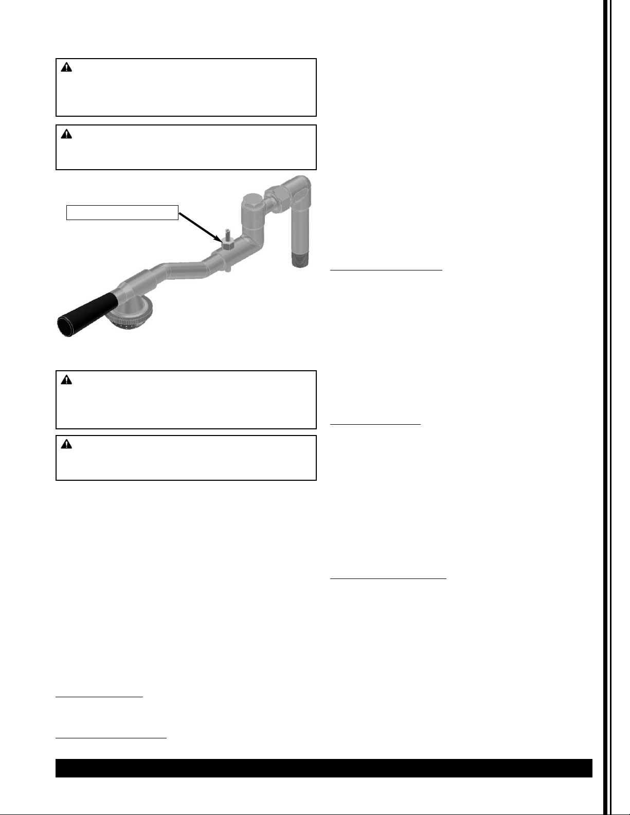
Spray Arm Assembly
The new improved spray head system was designed to
facilitate easier cleaning and maintenance. The swivel
valve has a larger flow opening and the spray head cap
is equipped with a stainless steel disc, used to control
the flow of water.
When ordering replacement parts, be sure to order the
correct disc and spray cap for each urn, as shown in
Parts Diagram Illustration.
• To prevent lime buildup, especially in hard water
areas, remove and clean spray head cap and spray head
disc frequently.
• To clean swivel valve loosen nut and remove spray arm
assembly from urn.
• Remove sediment by inserting a pipe cleaner through
small hole in valve.
• If maximum setting of timer fails to deliver enough
water, check water pump.
If Water Fails To Heat
1. Check line fuse or circuit breaker. Replace or reset
if necessary.
2. Make sure thermostat is in ON position. If
thermostat pilot light does not come on, replace
thermostat. (Refer to instructions below.) If pilot
light is on, measure continuity between terminals l
and 2 of thermostat, and between terminals 3 and
4. If a resistance is measured, replace thermostat.
3. If thermostat is okay, check wiring and repair if
necessary: if wiring is okay, check heater resistance;
if high or infinite, replace as follows:
Replacing Heater
1. Shut off power and disconnect water supply at
elbow. Drain urn.
2. Remove one coffee gauge glass, faucet, shank, and
liner.
3. Tilt urn and disconnect wires to heater.
4. Remove socket head screw and heater flange and
lift heater out.
5. Install new heater and reassemble urn.
6. Repeat Priming instructions on page 6. NOTE: DO
NOT TURN ON THERMOSTAT UNTIL URN IS
PRIMED.
Replacing Thermostat
(All Models)
Thermostat is located in side box of urn. Lift off side box
door to gain access to thermostat; then follow
instructions below.
1. Shut off power, disconnect water supply, and drain
urn by opening hot water faucet. When faucet
stops running you are ready to remove the
thermostat bulb.
2. Remove thermostat knob and two screws holding
thermostat in place.
3. Disconnect wires from thermostat.
4. Pull out thermostat bulb.
5. Install new thermostat, push in the new thermostat
bulb. Tighten compression nut on thermostat fitting
to prevent leaking. (continued next page)
WARNING: SHOCK AND BURN HAZARD
To prevent electric shock and burn hazard, all tasks
described in this section are to be performed by a
trained and qualified service technician.
WARNING: SHOCK HAZARD
Disconnect power before attempting any electrical
repairs.
Bypass Adjustment
WARNING: SHOCK AND BURN HAZARD
To prevent electric shock and burn hazard, all tasks
described in this section are to be performed by a
trained and qualified service technician.
WARNING: SHOCK HAZARD
Disconnect power before attempting any electrical
repairs.
Page 10

6. Repeat Priming instructions on page 6. NOTE: DO
NOT TURN ON THERMOSTAT UNTIL URN IS
PRIMED.
If Water from Cold Water Supply Line Does Not
Enter Urn
1. Check water supply to external shut-off valve.
2. Check fuse on rear of side box and replace if
necessary.
3. If water supply and fuse are okay, remove fuse and
lift off side box door exposing terminal block and
electrical wiring.
4. Check dual probe liquid level controller. (See
Component Tests)
If Water Runs Out At Overflow Drain
1. Make sure urn is level and overflow tube is vertical.
2. Remove fuse from rear of side box.
3. If water continues to flow, solenoid valve is dirty or
not seating properly. Replace solenoid as described
below.
Replacing Solenoid
1. Shut off water supply, remove fuse, and lift off side
box door.
2. Disconnect wires from solenoid: then remove flare
nut and unscrew solenoid valve from bracket.
3. Install new solenoid and reinstall fuse and side box
door.
4. If necessary, follow Priming instructions on page 6.
No Water from Spray Head
1. Check fuse first.
2a For FE urns: Depress BREW switch and release. If
switch remains lit, water pump is probably not
operating. Lift off side box door and check if fan on
water pump is rotating. If not, replace pump as
described below.
2b. For CL urns: Turn brew timer knob clockwise.
Replace timer if it does not go on. If timer goes on
but pump doesn't, replace pump.
Replacing Water Pump
1. Shut off water supply and remove fuse. Drain urn
to level of water faucet.
2. Lift off side box door and disconnect the two pump
wires.
3. Loosen union fittings on pump and remove pump
from urn.
NOTICE: If your urn has older style
pump with copper connections, it is imperative
that you use a counter wrench when removing
and installing pump to avoid damaging copper
tubing. DO NOT OVERTIGHTEN.
4. Replace pump and follow Priming instructions on
page 6.
Checking Solid-State Timer (FE Urns)
1. Press and hold BREW switch for 10 seconds. Brew
cycle should start. If water stops coming from spray
head as soon as BREW switch is released, timer is
not operating. Replace it. (Instructions below.)
2. If no water comes from spray head when BREW
switch is pressed, replace switch.
NOTE: To check mechanical timer on CL urns, refer to
No Water from Spray Head.
Replacing Solid-State Timer
1. Remove fuse, lift off side box door, and remove
timer from bracket.
2. Carefully note locations of colored wires on timer
board and then remove wires.
3. Replace timer and reassemble unit in reverse order.
Blending - Automatic Type (FE Urns)
Operation:
The agitator pump circuit is programmed to operate
immediately after brewing cycle. The circuit pumps air
through the coffee gauge glass(es) into the coffee
liner(s). The complete cycle takes about 20 seconds. For
additional blending, simply press the BLEND switch.
Maintenance:
• If agitation is not sufficient to blend coffee, check
flexible tubing, and glasses and fittings, for possible air
leaks. Replace as necessary.
• If agitator pump does not operate immediately after
brewing cycle or when BLEND switch is pressed, replace
agitator pump or solid state agitator timer.
• If agitator pump comes on immediately after brewing
cycle, but does not operate when BLEND switch is
pressed, replace BLEND switch.
Blending - Manual Type (CL Urns)
Operation:
Immediately after brewing cycle, depress BLEND switch
and hold for about 20 seconds. Your coffee will be
completely blended and ready to serve.
Maintenance:
• If agitator pump does not operate when BLEND
switch is pressed, replace switch, if pump still does not
operate, replace pump.
10 Cecilware
®
Coffee Urns
WARNING: SHOCK AND BURN HAZARD
To prevent electric shock and burn hazard, all tasks
described in this section are to be performed by a
trained and qualified service technician.
WARNING: SHOCK HAZARD
Disconnect power before attempting any electrical
repairs.
Maintenance (continued)
Page 11

Coffee Urns Cecilware
®
11
Component Tests
Water Inlet Valve Test
1. Turn power OFF. If the water level rises inside a
partially filled tank, the Water Inlet Valve is leaking.
2. Disconnect wires from the Water Inlet Valve coil and
connect a 2 wire line cord to the terminals. Plug it
into a 115V outlet. If water flows in and stops when
you pull it out, the Valve is working fine. Repeat this
test a few times. The problem may be in the Probe
or Water Level Control Board.
3. If the water does not flow in when the cord is
plugged into an electrical outlet, the Solenoid coil
may be damaged, opened or the valve may have an
obstruction preventing the water from flowing in.
4. Clean or replace it.
Dual Probe Test
If lack of water persists, check the probe as follows:
1. Turn on the power and water supply. Check inside
the tank to make sure the water is below the Probe.
Pull the BLUE wire and terminal OFF the Probe rod.
2. If water still does not flow after the wire is
disconnected from the Probe, the problem may be
in the Solid State Dual Level Control Board.
3. If water starts flowing into the tank, the Probe may
be grounded, due to excessive liming. Check with
Ohm meter.
4. Clean or replace probe.
Dual Probe Liquid Level Controller Test
Check the Controller as follows:
1. Make sure there is power input to the Controller at
the terminals AC1 & AC2. Your voltmeter should
read 115 Volts. It should read the same at terminals
AC1 & FILL when the water level is low. This is the
output power to actuate the coil of the Solenoid
Valve to open it.
2. The lack of voltage at terminals AC1 & L-LEVEL or
H-LEVEL indicates that the Controller is not working
properly.
3. Make sure all wire connections are tight, including
ground.
4. If after this, the Controller is still failing to open the
Water Inlet Valve, replace it.
Maintenance (continued)
Hose Nut Assembly
Blue
WARNING: SHOCK AND BURN HAZARD
To prevent electric shock and burn hazard, all tasks
described in this section are to be performed by a
trained and qualified service technician.
WARNING: SHOCK HAZARD
Disconnect power before attempting any electrical
repairs.
Page 12

12 Cecilware
®
Coffee Urns
Parts Diagram
9
E
L
C
F
AUTOMATIC COFFEE URNS
17
Page 13

Coffee Urns Cecilware
®
13
Parts Diagram (continued)
E20
0
N
,
C
L
0
0
N
y
FAUCET, HOT WATER
FAUCET, COFFEE
SPRAY ARM ASSEMBLY
AUTOMATIC COFFEE URNS
FE300-N
of timer fails to deliver enough water, check water pump.
To prevent lime buildup, especially in hard water areas, remove and clean spra
remove spray arm assembly from urn.
head cap and spray head disc frequently. To clean swivel valve, loosen nut and
Remove sediment by inserting a pipe cleaner through small hole in valve.
If maximum setting
Page 14

14 Cecilware
®
Coffee Urns
Parts Diagram (continued)
Page 15

Coffee Urns Cecilware
®
15
Parts List
ITEM PART DESCRIPTION QUANTITY
# FE75N FE75N CL75N FE100N FE100N CL100N FE200N CL200N FE300N
DUAL DUAL DUAL
BREW BREW BREW
1 B157A TERMINAL BLOCK 4 WIRE 1 1 1 1 1 1 1 1 1
2 C036AL CONTACTOR, 3 POLE, 50 AMP - (240V) - - - - - - - - -
CG12AL CONTACTOR, 3 POLE, 50 AMP - 120V 1 1 1 1 1 1 1 1 1
3 C395AL FUSE 6A SC-6 1 1 1 1 1 1 1 1 1
4 C396AL FUSEHOLDER, SC-6 1 1 1 1 1 1 1 1 1
5 C511A AIR PUMP, AGITATOR (120V ONLY) 1 1 1 1 1 1 1 1 1
C512A AIR PUMP, AGITATOR (220V) - - - - - - - - -
6 CD318 WATER INLET VALVE (120V ONLY), .70 GPM - - - - - - - - 1
CD319 WATER INLET VALVE (240V), .70 GPM - - - - - - - - CD417 WATER INLET VALVE (120V ONLY), .35 GPM 1 1 1 1 1 1 - - CD418 WATER INLET VALVE (240V), .35 GPM - - - - - - - - CD423 WATER INLET VALVE (120V ONLY), .50 GPM - - - - - - 1 1 CD424 WATER INLET VALVE (240V), .50 GPM - - - - - - - - -
7 CH362 WIRING HARNESS 1 1 - 1 1 - 1 - 1
CH387 WIRING HARNESS (MECH. TIMER) - - 1 - - 1 - 1 -
8 D001B SIGHT GLASS ASSEMBLY (COFFEE) 1 1 1 2 2 2 - - -
D020B SIGHT GLASS ASSEMBLY (COFFEE) - - - - - - 3 3 D031B SIGHT GLASS ASSEMBLY (COFFEE) - - - - - - - - 2
9 D017Q FAUCET, SHANK ASSEMBLY (COFFEE) 1 1 1 2 2 2 2 2 2
10 D022Q FAUCET, SHANK, VALVE ASSEMBLY (WATER) 1 1 1 1 1 1 1 1 1
11 D024A SIGHT GLASS ASSEMBLY (WATER) 1 1 1 1 1 1 - - -
D032A SIGHT GLASS ASSEMBLY (WATER) - - - - - - - - 1
12 E000A WATER PUMP (120V ONLY) (Prior to 3/2014) 1 1 1 1 1 1 1 1 1
E070A WATER PUMP (240V) (Prior to 3/2014) - - - - - - - - A533-033 WATER PUMP (120V ONLY) (After 3/2014) 1 1 1 1 1 1 1 1 1
A533-034 WATER PUMP (240V) (After 3/2014) - - - - - - - - -
13 E009A OVERFLOW FITTING W/ NUT 1 1 1 1 1 1 1 1 1
14 235-00008 COMPLETE SPRAY ARM ASSY W/ BYPASS - - - - - - - - 1
235-00009 COMPLETE SPRAY ARM ASSY W/ BYPASS 1 1 1 1 1 1 - - 235-00010 COMPLETE SPRAY ARM ASSY W/ BYPASS - - - - - - 1 1 -
15 320-00015 HEATER ELEMENT 5KW 240V 1PH - - - - - - 2 2 3
16 320-00016 HEATER ELEMENT 8KW 240V 1PH - - - 1 1 - - - -
17 320-00020 HEATER ELEMENT 7KW 240V 1PH 1 1 1 - - 1 - - -
18 H429Q TUBE, OVERFLOW 1 1 1 1 1 1 - - -
19 K491B HOSE NUT ASSEMBLY (BRITISH THREAD) 1 1 1 1 1 1 1 1 1
20 H416A WATER INLET TUBE (Prior to 3/2014) 1 1 1 1 1 1 1 1 1
20 H416A WATER INLET TUBE (After 3/2014) 1 1 1 1 1 1 1 1 1
21 K808A RETAINER MOUNTING BLOCK 2 2 2 3 3 3 3 3 3
22 K810Q LEVEL SENSOR, DUAL PROBE 1 1 1 1 1 1 1 1 1
23 L007A THERMOMETER, BREW DIAL 1 1 1 1 1 1 1 1 1
24 L154A TIMER, MECHANICAL (0 - 15 MINUTES) - - 1 - - 1 - 1 -
25 L205A TIMER, SINGLE (120V) 1 - - 1 - - - - 1
L210A TIMER, SINGLE (240V) - - - - - - - - L214A TIMER, DUAL (120V) - 1 - - 1 - 1 - L216A TIMER, DUAL (240V) - - - - - - - - -
26 L155A ROCKER SWITCH, POWER ON-OFF 1 1 1 1 1 1 1 1 1
27 L238A DELAY TIMER-SOLID STATE (120V) 1 1 1 1 1 1 1 1 1
L253A DELAY TIMER-SOLID STATE (240V) - - - - - - - - -
28 L780A THERMOSTAT 25A, URNS 1 1 1 1 1 1 1 1 1
29 L584A SWITCH, PUSHBUTTON 3 4 - 3 4 - 4 - 3
30 L775A DUAL LEVEL CONTROL HI-LO (120V) 1 1 1 1 1 1 1 1 1
L776A DUAL LEVEL CONTROL HI-LO (220V ONLY) - - - - - - - - -
31 M005S LEGS (4" ADJ) (4 PER BAG) 1 1 1 1 1 1 1 1 1
32 M008A KNOB THERMOSTAT 1 1 1 1 1 1 1 1 1
33 M016A THERMOSTAT BEZEL 1 1 1 1 1 1 1 1 1
34 M027A KNOB, URN COVER 1 1 1 2 2 2 2 2 2
35 M326A WATER INLET HOSE 3/8 x 5/8 x 8" 1 1 1 1 1 1 1 1 1
36 M461A SILICONE GROMMET 12mm 3 3 3 3 3 3 3 3 3
37 M462A SILICONE GROMMET 15mm - - - - - - - - -
38 M876A BLUE BUTTON (BLEND) 1 1 1 1 1 1 1 1 1
39 M877A GREEN BUTTON (BREW) 2 2 - 2 2 - 2 - 2
40 MA15A COPPER GASKET, TEFLON FILLED 6 6 6 7 7 7 7 7 7
41 Q027Q LINER ASSY & COVER (FE75/ FE100) 1 1 1 2 2 2 - - -
Q094Q LINER (FE300) - - - - - - - - 2
Q204Q LINER ASSY & COVER (FE200) - - - - - - 2 2 -
42 UB17A SIGHT GLASS RETAINER 2 2 2 3 3 3 3 3 3
43 V002A BREW BASKET, FE75 / FE100 1 1 1 1 1 1 - - -
V003A BREW BASKET, FE200 - - - - - - 1 1 V081A BREW BASKET, FE300 - - - - - - - - 1
44 32004 INDICATOR LIGHT W/ RED LENS 2 3 - 2 3 - 3 - 2
45 ABB3WP FILTER PAPER (FE75N/FE100N) 1 1 1 2 2 2 - - -
ABB6WP FILTER PAPER (FE200N) - - - - - - 2 2 ABB810WP FILTER PAPER (FE300N) - - - - - - - - 2
Page 16

16 Cecilware
®
Coffee Urns
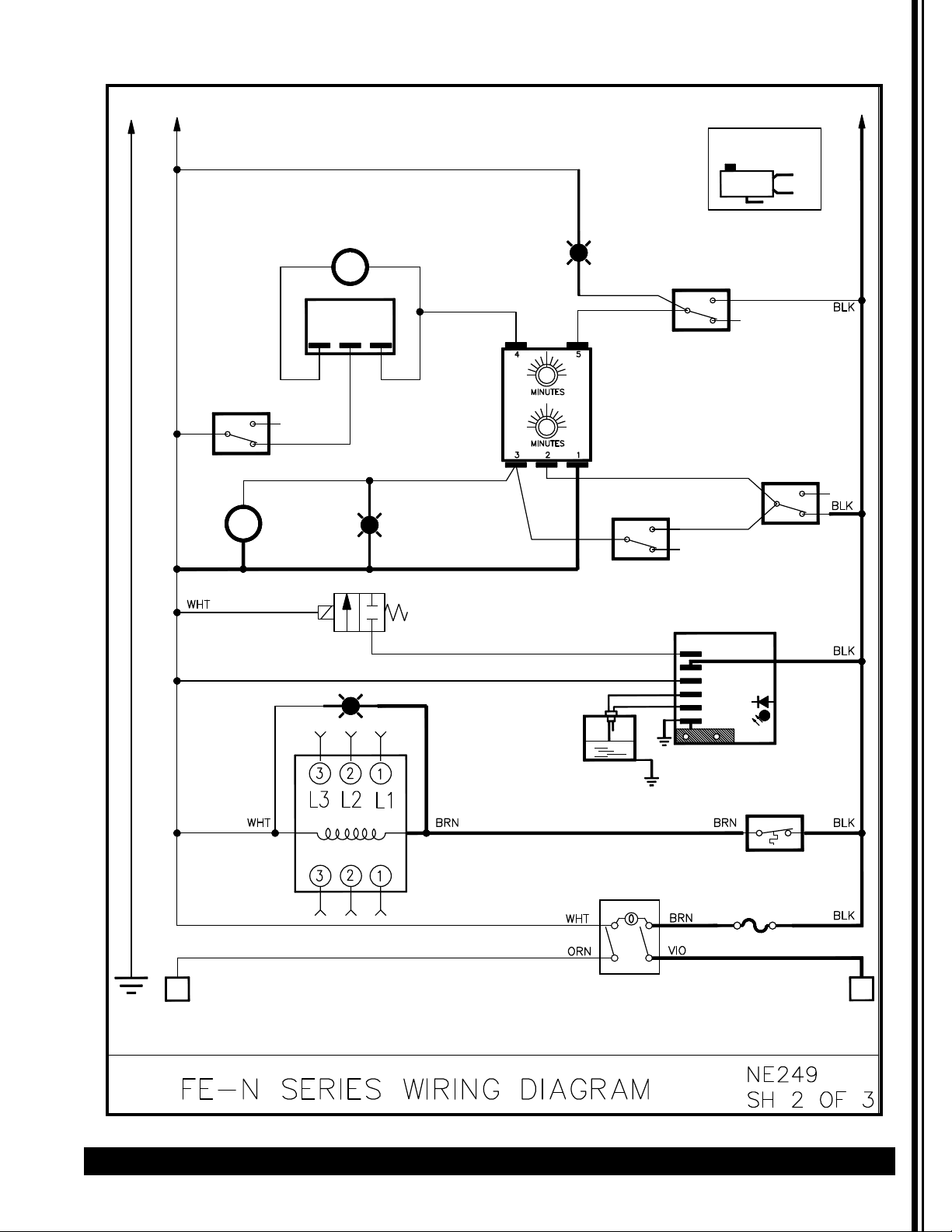
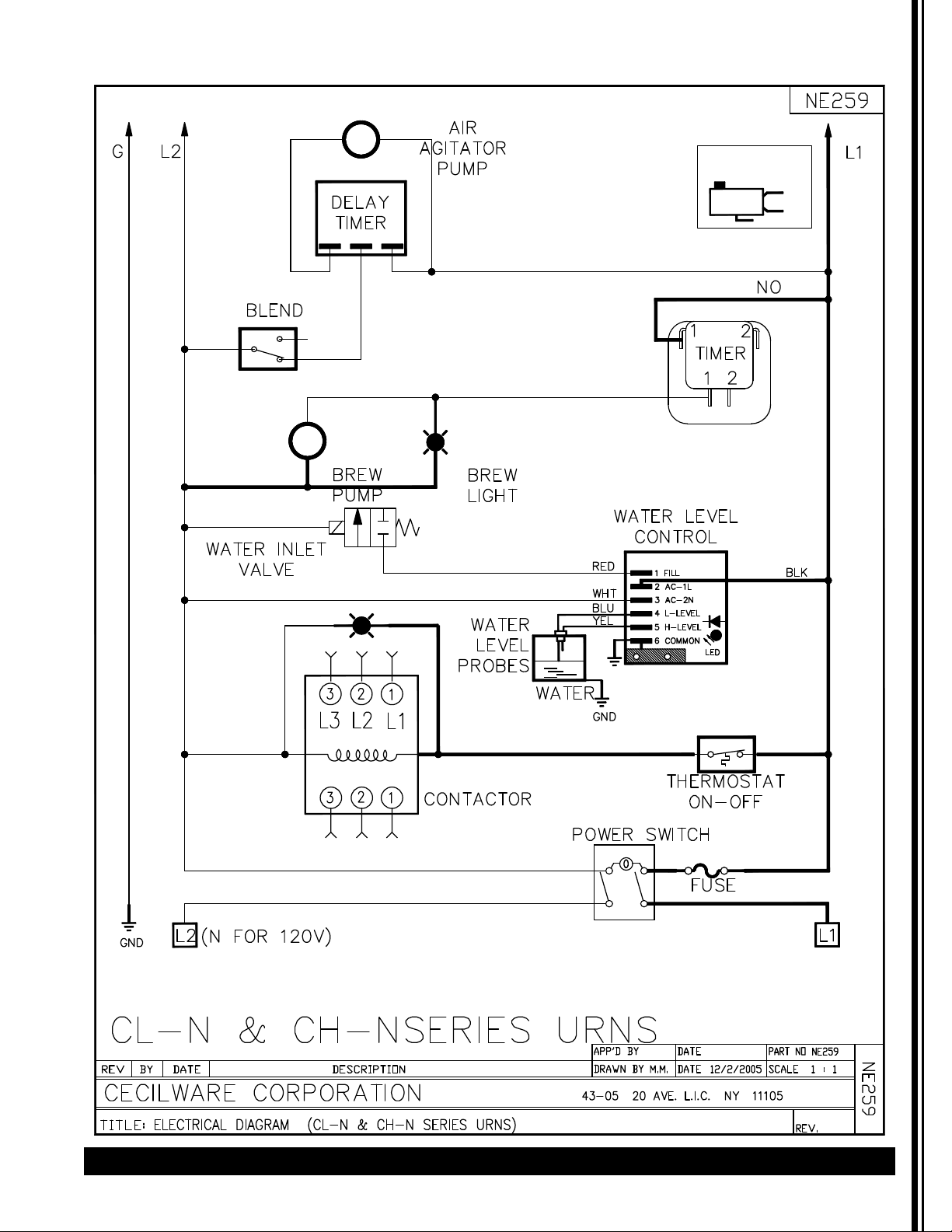
Wiring Diagram
GND
L2
FE-N SERIES W/ SINGLE TIMER
AIR AGITATOR PUMP
L1
SWITCH
CONFIGURATION
NC
C
BLEND
Yel
NO
NC
Yel
BREW
PUMP
DELAY
TIMER
Blue
Wht
Yel
Blue
Yel
BREW
LIGHT
WATER
INLET
VALVE
Gray
Wht
WATER
LEVEL
PROBES
SINGLE
TIMER
Yel
C
Red
NO
Red
NC
BREW
SWITCH
WATER LEVEL CONTROL
RED
WHT
BLU
YEL
1 FILL
2 AC-1L
3 AC-2N
4 L-LEVEL
5 H-LEVEL
6 COMMON
C
NO
STOP
NO
C
NC
LED
CONTACTOR
(N FOR 120V)
L2
GND
WATER
GND
THERMOSTAT
FUSE
POWER SWITCH
L1
Page 17
Coffee Urns Cecilware
®
17
Wiring Diagram (continued)
FE-N SERIES W/ DUAL TIMER
L2
GND
Wht
AIR AGITATOR PUMP
DELAY
TIMER
Gray
Wht
BREW
LIGHT
Purple
Purple
BREW
SWITCH
C
SWITCH
CONFIGURATION
NC
C
NO
NO
NC
L1
Wht
BLEND
C
Yel
NO
NC
Yel
BREW
PUMP
Blue
Yel
Wht
Blue
Yel
HALF
BREW
LIGHT
WATER
INLET
VALVE
Wht
WATER
LEVEL
PROBES
DUAL
TIMER
HALF BREW
SWITCH
Yel
C
WATER
Red
STOP
C
NO
Red
NC
WATER LEVEL CONTROL
RED
WHT
BLU
YEL
GND
1 FILL
2 AC-1L
3 AC-2N
4 L-LEVEL
5 H-LEVEL
6 COMMON
LED
NO
NC
CONTACTOR
(N FOR 120V)
L2
GND
THERMOSTAT
FUSE
POWER SWITCH
L1
Page 18
18 Cecilware
®
Coffee Urns
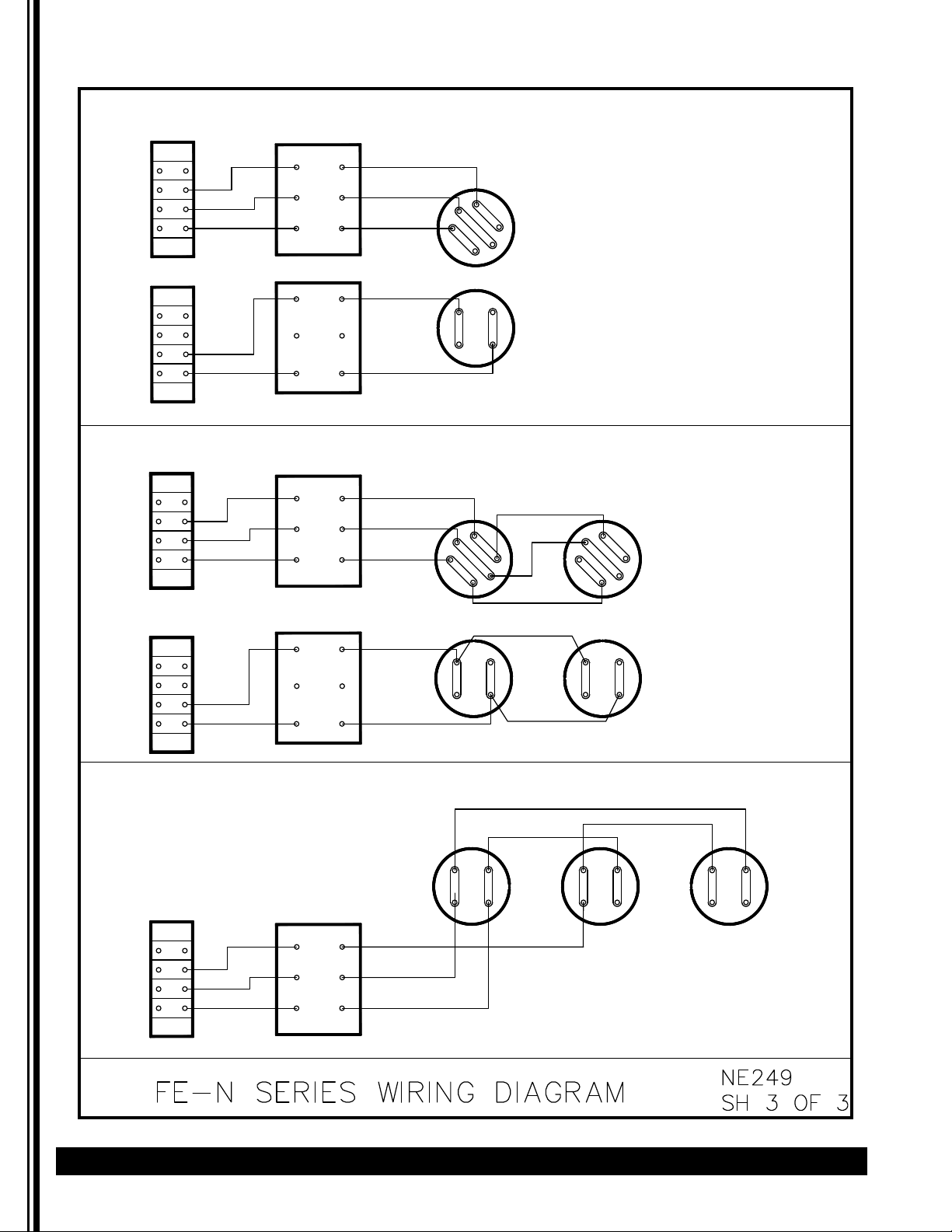
Wiring Diagram (continued)
3 GALLON - SINGLES & TWINS
TERMINAL
BLOCK
TERMINAL
BLOCK
TERMINAL
BLOCK
CONTACTOR
CONTACTOR
L1 L2 L3 N L1 L2 L3 N
3
2
1
3 PHASE
HEATER
1 PHASE
HEATER
G026A (8 KW)
G024A (6 KW)
G013A (8 KW)
G031A (7 KW)
6 GALLON TWINS
CONTACTOR
3
2
1
3
2
1
3 PHASE
HEATER
3 PHASE HEATERS
G018A (5 KW EACH)
TERMINAL
BLOCK
TERMINAL
BLOCK
CONTACTOR
L1 L2 L3 N L1 L2 L3 N
1 PHASE
HEATER
1 PHASE HEATERS
G011A (5 KW EACH)
9 GALLON TWINS
1 PHASE HEATERS
G011A (5 KW EACH)
CONTACTOR
L1 L2 L3 N
15 KW, 3 PHASE
Page 19
Coffee Urns Cecilware
®
19
Wiring Diagram (continued)
SWITCH
CONFIGURATION
NC
C
NO
NO
C
NC
Page 20

Grindmaster-Cecilware
4003 Collins Lane, Louisville, KY 40245 USA
Phone: 502.425.4776 Toll Free: 800.695.4500
Fax: 502.425.4664
Web: gmcw.com Email: info@gmcw.com
©2016 Grindmaster-Cecilware
Printed in USA
0516 Form # CW-326-01
Part # 390-00070
 Loading...