

Cecilware FE-100G Operation Manual
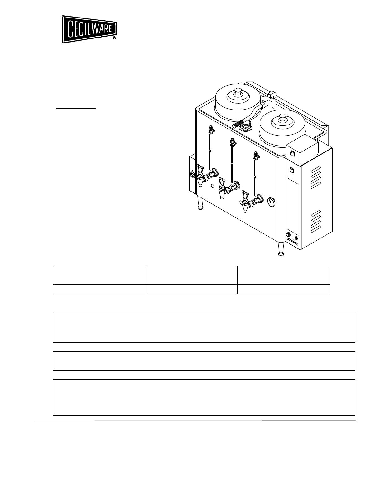
AUTOMATIC GAS
COFFEE URN
OPERATION MANUAL
MODEL:
FE-100G
SPECIFICATI ONS
I NSTALLATI ON
MAI NTENANCE TI PS
REPAIR PARTS LI ST
WI RING DI AGRAMS
GAS SPECI FI CATI ON S
MODEL NO. NATURAL GAS
BTU/ HR @ 3. 5” W.C.
FE- 100 G 32, 000 32, 000
PROPANE GAS
BTU/ HR @ 10 ” W.C.
FOR YOUR SAFETY
DO NOT STORE OR USE GASOLINE OR OTHER FLAMMABLE VAPORS AND
LIQUIDS IN THE VICINITY OF THIS OR ANY OTHER APPLIANCE.
THIS INSTALLATION MUST CONFORM WITH THE NATIONAL FUEL GAS CODE,
ANSI Z223.1 (LATEST EDITION).
WARNING: IMPROPER INSTALLATION, ADJUSTMENT, ALTERATION, SERVICE
OR MAINTENANCE CAN CAUSE PROPERTY DAMAGE, INJURY OR DEATH. READ
THE INSTALLATION, OPERATING AND MAINTENANCE INSTRUCTIONS
THOROUGHLY BEFORE INSTALLING OR SERVICING THIS EQUIPMENT.
CECILWARE CORPORATION
43-05 20TH AVENUE, LONG ISLAND CITY, NY 11105-1295
• 718 932-1414
N529A 08/99 DS

SAFETY PRECAUTI ON S
FOR Y OUR SAFETY, T HE FO LLO W I NG SAFETY PRECAU TI ON S SH O ULD
BE FOLLOW ED AN D EN FORCED .
I F YOU SMELL GAS:
• OPEN WI NDOWS
• DON’T TOUCH ELECTRI CAL SWI TCHES
• EXTI NGUI SH OPEN FLAMES
• I MMEDI ATELY CALL YOUR GAS SUPPLI ER
1. I nst r uct ions m ust be post ed in a pr om inent locat ion and all safet y
precaut ions tak en in t he event t h e u ser sm ells gas. Obt ain t his
in form at ion fr om y our local gas supplier .
2. LI GHTI NG:
Follow t he inst ruct ion on page 6 and label at t ached t o
right side of coffee ur n.
3. Do not place any t hing ov er t he flue opening.
4. Do not place com bust ibles or non- com bu st ible m at erials in t he
proxim it y of cof fee u rn as t his could cause fires or obst r uct air flow to
th e m ain bur ners.
5. This installation m ust con form wit h local codes, or in absence of local
codes w it h t he Nat ional Fuel Gas Code ANSI Z2 23. 1, lat est edit ion.
6. Provide adequat e air su pply and vent ilat ion.
7. Provide adequat e clear ance for air openings int o t he com bu st ion
cham ber.
8. Provide clear an ce for serv icing an d proper oper ation. Minim u m
clear an ce fr om com bust ible constr uction 8” fr om back and 6” fr om
side.
9. Boiler m ust be disconn ect ed from gas supply during any pressu re
test ing of pipelin es in excess of ½ psig, and isolat ed ( by t urn ing off
gas shut - off v alv e) d uring an y test ing less t han ½ psig.
10. Ret ain t his m anual for f ut ur e reference.
UNPACKI NG I NSTRUCTI ON:
Car ef ully un pack t he coffee ur n and inspect
im m ediat ely for sh ipping dam ages. Your au tom at ic coffee urn w as
shipped in a car t on designed t o giv e m axim u m pr ot ection in norm al
handlin g. I t was t horough ly inspect ed bef or e leav in g t he fact or y and t he
carr ier accept ed and sig ned for it . File any claim s for shippin g dam age or
ir r egu lar it ies wit h th e carr ier .
ELECTRICAL CONNECTIONS:
Cord Type Plug- in
12 0 VAC, 15 AMP, 50/ 60 Hz
POWER REQUI REMENTS:
3 AMP @ 12 0 VAC, 50 / 60 Hz
2
FE-100G
AUTOMATIC
COFFEE URN
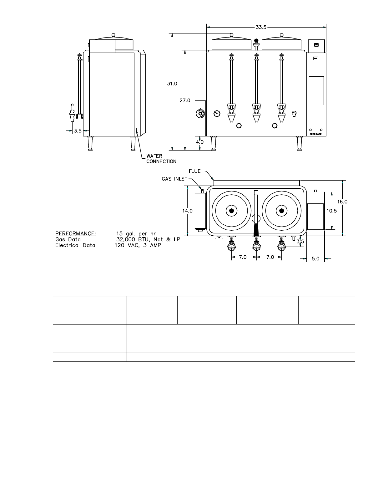
FE- 1 0 0 G AUTOM ATI C CO FFEE U RN
Dim ensions
( in ch)
16 .0 19. 5 31. 0 3 7.0
Wat er
connect ion
Constr uct ion Type 30 4 18- 8 St ainless St eel
Shipping Wt . 1 25 lb.
I NSTALLATI ON AN D OPERATI N G I N STRUCTI ON :
PRE-I NSTALLATI ON I NSTRUCTI ONS:
m ust be m ade by a licensed plum ber an d t he inst allation m ust conform
wit h Stat e and Local Codes or in absence of Local Codes, w it h t he
Nat ion al Fuel Gas Code ANSI Z22 3.1 a lat est v ersion.
Body
Dept h
¼ ” Copper t ubing
Overall
Dept h
The installation of your coffee urn
Overall
Height
Overall
Widt h
3

AI R SUPPLY AND VENTI LATI ON:
Adequat e vent ilat ion and air supply
m ust be prov id ed in order for t he coffee urn t o operat e properly and
eff icien t ly . The area in fr ont of and above t he u nit m ust be clear t o avoid
an y obstr uct ion of flow of com b ust ion and vent ilat ion air. DO NOT under
an y circu m st ances, con nect t he coff ee ur n f lu e direct ly t o a bu ilding
ex haust syst em or place t he flue out let direct ly int o t he plen um of t he
ex haust hood as it w ill adv er sely affect t he gas com bust ion of t h e coffee
urn .
CLEARANCES:
Your coffee ur n is d esig n cer t if ied to u se on com bust ible
floor s. The side and b ack clearan ces for com b ust ible const r uctions are as
follow s: 6 in ches from side and 8 inches from back. The cof fee u rn m ust
be in st alled w it h 4 inch high legs pr ovided.
GAS CONNECTION:
Exam in e the gas specif ication label at tached t o t he
urn t o be cert ain t hat t he t y pe of gas for w hich the unit is equ ipped is
th e sam e as t he gas supply . A 3/ 8 NPT gas connect ion is n eeded t o
connect t h e u nit t o t he gas line. An accessible m an ual shu t- off valve
m ust be in st alled in t he gas su pply line in case of an em ergency. The gas
supply pipe m ust be sized t o accom m odate all t he gas fir ed equipm ent
th at m ay be con nect ed t o it . Check wit h your local Gas Com pan y as t o
proper p ip e size. Sealan t on all pipe j oin t s m ust be resist ive t o propane
gas. Befor e at t em pt ing t o lig ht t he coff ee ur n, ch eck all j oint s for gas
tigh t ness u sing a soap an d wat er solut ion .
WATER CONNECTION:
Unit is supplied wit h a wat er st rainer and a 19”
lengt h of ¼ ” copper t ubing w it h a flare fit t ing. Connect t he copp er t ubing
wit h t h e f lar e fit t in g t o t he w at er conn ection at th e rear of th e m achine.
The oth er end of t he st rainer is con nect ed wit h a suit able lengt h of ¼ ”
tu bing and a shut - off v alve ( sup plied by a plum ber ) t o a cold w at er
supply . Wat er pr essur e should be m inim um of 20 lbs. for proper
oper ation.
To t urn on t he w ater sup ply v alv e plug t he line cor d int o a 12 0 V
grounded ou t let . The w at er will st ar t en t er ing t he un it an d aut om at ically
fill it to capacit y.
LI GHTI NG AND ADJUSTMENT:
Wat er m ust be visible in t he sight glass
befor e light ing t o pilot . Tu rn t he t herm ost at k nob t o it s low est posit ion.
Turn gas cock d ial t o PILOT posit ion. Depress gas cock d ial and light pilot
wit h a long light ed m at ch t hrou gh t he opening locat ed on t he bot t om of
th e urn . Hold in depressed posit ion for approxim at ely 3 0 sec. or unt il
pilot r em ain s lit w hen dial is r eleased.
NOTE: On t he fir st ligh t in g it m ay be necessary t o hold t h e dial for a
longer period t o allow t r apped air t o escape fr om t he line.
DI AL SETTI NGS AND CORRESPONDI NG WATER TEMPERATURES:
“ 1” = 50F, “ 1 0” = 198F
4
 Loading...