

Page 1
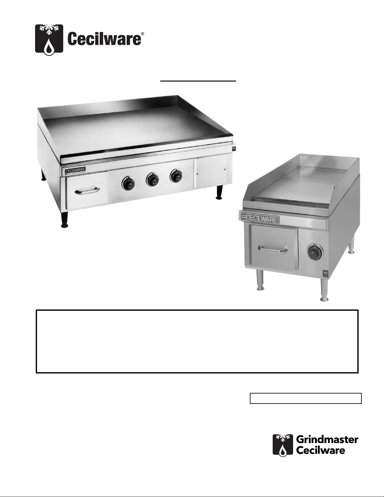
Electric Griddle
Operator Manual
EL1812, EL1836
Grindmaster-Cecilware
4003 Collins Lane, Louisville, KY 40245 USA
Phone: 502.425.4776 Toll Free: 800.695.4500
Fax: 502.425.4664
Web: gmcw.com Email: info@gmcw.com
Safety Information .....................................2
Unpacking...................................................2
Installation..................................................2
Preparing Griddle.......................................3
Operation....................................................3
Cleaning......................................................4
Maintenance...............................................4
Parts Diagram and List ...............................5
Wiring Diagram..........................................6
Thank you for purchasing this quality Griddle. For your safety and the safety of others, read all warnings
and the operator’s manual before installing or using the product. Properly instruct all operators. Keep
training records. For future reference, record serial number here:
Table of Contents
©2016 Grindmaster-Cecilware
Printed in USA
0916 Form # CW-335-01
Part # 390-00082
Grindmaster-Cecilware provides the
industry’s BEST warranty. Visit gmcw.com
for warranty terms and conditions.
Model: EL1812
Model: EL1836
Page 2

2 Cecilware
®
Electric Griddle
Important Safety Information
This is the safety alert symbol. It is used to alert you to potential personal injury hazards. Obey all safety messages
that follow this symbol to avoid possible injury or death.
WARNING
• Do not deform power cord.
• Follow national and local electrical codes.
• Do not store or use gasoline or other flammable vapors and liquids in the vicinity of this or any other
appliance.
• Use only on a dedicated circuit load that is properly protected and capable of the rated load. Do not use
extension cords as this could result in electrical shock, overheating, and fire.
• Risk of electrical shock. Disconnect power before servicing or cleaning unit. Contact Grindmaster-Cecilware
Technical Service for service assistance.
• If the supply cord is damaged, it must be replaced by the manufacturer, its service agents, or similarly
qualified persons in order to avoid a hazard.
• Due to the heat a griddle may produce, it must be placed on a non-combustible surface with at least 1
inch clearance from all combustible surfaces at side and rear.
FAILURE TO COMPLY TO THE ABOVE RISKS PERSONAL INJURY, SHOCK HAZARD, FIRE, OR DAMAGE TO
EQUIPMENT.
CAUTION
• Read and understand the operating instructions in this manual thoroughly. Only allow properly trained
persons to operate this machine.
• Stay alert at all times during operation.
• Operate with care. Surfaces will get very hot and may cause serious burns.
NOTICE
• Keep operating area clean.
For your safety and the safety of others, read all warnings and the operator’s manual before installing or using
the product.
DANGER: This term warns the user of imminent hazard that will result in serious injury or death.
WARNING: This term refers to a potential hazard or unsafe practice, which could result in serious injury or
death.
CAUTION: This term refers to a potential hazard or unsafe practice, which could result in minor or moderate
injury.
NOTICE: This term refers to information that needs special attention or must be fully understood.
Unpacking
For EL1836 Unit only: Cut the two plastic straps around
shipping container and lift off top of container,
exposing unit
For all units: Carefully lift unit out of shipping container,
and inspect immediately for shipping damage. Your
Griddle was shipped in a carton designed to give it
maximum protection. It was thoroughly inspected
before leaving the factory. File any claims for shipping
damage or irregularities directly with the carrier.
Installation
Component Assembly
Legs are shipped with unit in a plastic bag. Place a cloth
behind unit to protect the finish and turn it on its back.
Screw in the legs hand tight. Level unit after final
installation. Height may be adjusted by turning the feet
up or down as desired. It is best to tilt the griddle plate
a few degrees toward the front left-hand corner, where
the grease chute is located, to facilitate grease runoff.
NOTICE Unit must only be installed and operated
with legs provided by manufacturer.
Safety Information
Page 3
Electric Griddle Cecilware
®
3
Clearances
Distance required between combustible and noncombustible material: 1” rear and 1” sides.
Electrical Installation
FOR QUALIFIED SERVICE PERSONS ONLY
The griddle is not fused internally; therefore, it must be
connected to a fused circuit equipped with a suitable
disconnect as may be required by local electrical code.
The following table shows the fuse or circuit breaker
required for each griddle.
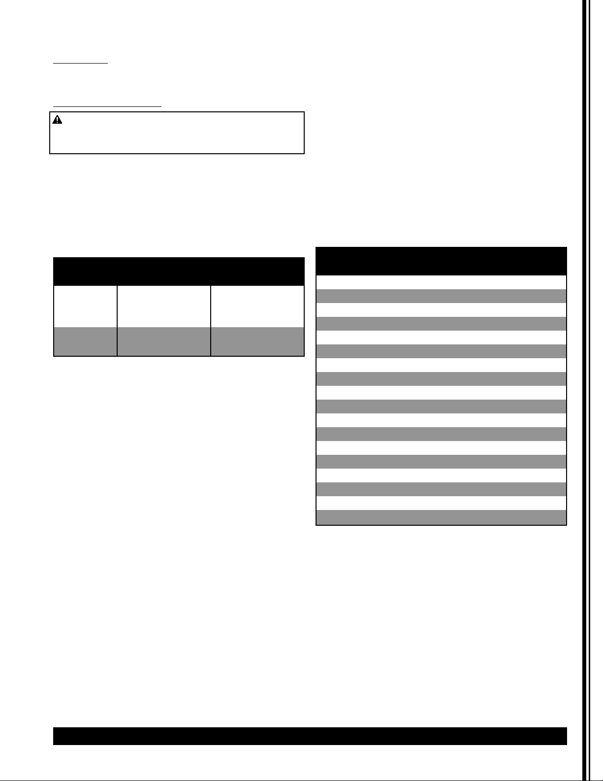
RECOMMENDED FUSE OR CIRCUIT SIZES FOR FIELD
WIRING OF ELECTRIC GRIDDLES
Before hooking up griddle read the electrical
specification label located on the back of electrical
access panel. Verify that the power supply available
matches the information on this label.
Extend conduit (flexible or rigid) and supply lines
through knockout in right-hand front corner of bottom
of griddle, under terminal block 7. Make sure wires are
at least the size shown on the electrical specification
label and on the wiring diagram for your model located
in this manual.
For single phase hook-up, connect one hot wire to
bottom terminal, L 1, of terminal block 7 and one hot
wire to top terminal, L2.
For three-phase hook-up, connect one hot wire to each
of the three terminals, L 1, L2 and L3 of terminal block
7.
Connect ground wire to ground lug 8 to comply with
electrical codes.
Test that all connections are tight; then replace
electrical access panel.
Preparing Griddle
Peel off paper covering griddle plate. The griddle
surface is protected with a protective coating. To
remove this coating, , set thermostat knob(s) to 200
degrees and wait for the griddle to heat up enough to
melt the protective coating. Immediately turn
thermostat knob(s) to OFF and use a cloth to wipe off
as much protective coating as possible. Then wipe the
cooking surface with griddle cleaner, rinse thoroughly
with water and wipe dry.
Apply a light coating of cooking oil or shortening to the
entire cooking surface. Your griddle plate is now ready
for normal operation.
Operation
Turn the thermostat knob(s) to the desired cooking
temperature and wait for the griddle to reach
operating temperature (when the pilot light(s) go out.)
Your griddle features independent heating zones, each
controlled by one thermostat. This allows different
types of food to be cooked at the same time in different
zones. Use the Cooking Chart below as a guide for
proper cooking temperatures and times required for
different foods.
Above data refers to the 208/240 units. Longer cooking
times expected for 120V unit.
A grease trough is provided at the front of the griddle
with a drain chute which empties into a grease drawer:
use spatula to loosen the soil on the griddle plate and
sweep it into the chute. Do not tap the edge of the
spatula on the griddle plate as this will mar the finish
of the polished surface and possibly cause food to stick
when cooking.
Installation (continued)
WARNING: Electrical shock hazard. This is high
voltage equipment. Make sure main disconnect is off
before hooking up griddle.
EL1812 EL1836
AMPS AWG AMPS AWG
120V 1PH 15 16 ‐ ‐
208V 1PH 15 14 50 8
240V 1PH 17 14 60 6
208V 3PH ‐ ‐ 40 8
240V 3PH ‐ ‐ 40 8
Cooking Chart
Food Temp (°F) Minutes
Hamburgers 350 1 1/2 ‐ 3
Cheese Sandwich 375 1 ‐ 3
Minute Steak 360 2 ‐ 3
Club Steak 350 3 ‐ 5
Beef Tenderloin 350 5 ‐ 7
Bacon 325 3 ‐ 5
Sausage 350 3
Pancakes 375 2
Fried Potatoes 340 3 ‐ 4
Eggs 300 2 ‐ 4
Bologna 375 2
Frankfurters 375 2 ‐ 3
Ham Loaf 375 2
Ham Steak 400 10
Peaches 350 2
Pineapple 350 2
Apple Slices 350 2
Onion Slices 350 4
Page 4

4 Cecilware
®
Electric Griddle
Cleaning
Keep the griddle clean by washing and using griddle
cleaners available from your dealer. Do not attempt to
use any steel wool or abrasives which will embed in the
plate.
Keep all exterior surfaces of the griddle free of splashed
grease and other dirt by washing regularly with hot
water and soap. Rinse and wipe dry: then polish with a
soft cloth.
Maintenance
FOR QUALIFIED SERVICE PERSONS ONLY
THERMOSTAT ADJUSTMENT: (See Parts Diagram.)
Problem: Temperature of griddle plate does not match
with thermostat knob setting.
1. Turn thermostat knob to 300 degrees.
2. Place a suitable thermometer on the griddle
surface, and wait until temperature
stabilizes.
3. Turn thermostat knob to match reading on
thermometer: then carefully remove knob
without disturbing setting.
4. While holding the thermostat shaft, place a
small screwdriver in the adjusting screw in
the center of the shaft.
5. If the pilot light is on, slowly turn the screw
clockwise until the light goes out. This
lowers the thermostat temperature. If the
pilot light is out, slowly turn the screw
counter-clockwise until the light comes on.
This raises the thermostat temperature.
Then turn clockwise just until the pilot light
goes out again.
6. Replace the thermostat knob. The
temperature of the griddle plate now
coincides with the thermostat knob setting.
Problem:
Griddle does not heat when thermostat
knob(s) turned ON. Pilot light(s) do not light.
Possible Cause: Loss of power to griddle.
Remedy: Check line fuses or circuit breakers at power
source.
Problem:
Only part of griddle plate works properly and
the thermostat pilot does not light on faulty part of
griddle.
Possible Causes:
A. Thermostat set too high or too low: needs
adjusting.
Remedy: Follow Adjustment procedure in
"THERMOSTAT ADJUSTMENT"
B. Faulty thermostat which must be replaced.
Remedy: Replace thermostat as follows:
1. Tilt griddle on its back.
2. Remove mounting screws and bottom cover
(18)
3. Disconnect wires from heating element.
4. Remove outer retaining cover (17).
5. Disconnect thermostat bulb from plate by
removing the two screws holding capillary
clamp (14).
6. Remove thermostat knob.
7. Remove the two screws holding thermostat
in place. Lift out thermostat and disconnect
the wires, tag ging them to be certain they
are replaced on the proper terminals of the
new thermostat.
8. Install new thermostat by following the
above procedure in reverse order.
9. Calibrate thermostat, following the
procedure in "THERMOSTAT
ADJUSTMENT" paragraph above.
Problem
: Thermostat(s) work properly, but there is
insufficient heat in one or more zones of griddle.
Possible Cause: Heating element(s) burned out on
zone(s) of plate not operating properly.
Remedy: Replace heating element(s) as follows:
1. Perform steps 1 through 5 of "Replace
Thermostat" procedure above.
2. Remove heating element retainer plate
(16).
3. Install new heating element by following
the procedure above in reverse order.
NOTE: DO NOT OVERTIGHTEN NUTS HOLDING HEATING
ELEMENT RETAINER PLATE (18) IN PLACE.
If you need help, call Grindmaster-Cecilware Technical
Service Department, (502) 425-4776 or (800) 695-4500
(USA & Canada only) (Monday through Friday 8 AM - 6
PM EST). Please have the model and serial number
ready so that accurate information can be given.
Prior authorization must be obtained from
Grindmaster- Cecilware for all warranty claims.
Grindmaster-Cecilware provides the industry’s BEST
warranty. Visit our website at GMCW.com for warranty
terms and conditions.
CAUTION: To avoid burns, allow griddle to cool
before cleaning.
CAUTION: Disconnect power from griddle before
attempting electrical repairs.
Page 5

Electric Griddle Cecilware
®
5
Parts Diagram and List
# Descripon 120V 208/240V
EL‐1812 EL‐1812 EL‐1836
1 Grease Drawer Front T485V T485V T453V
2 Grease Drawer Handle M022A M022A M022A
3 Grease Drawer T434V T434V T434V
4 Thermostat Knob M081A M081A M081A
5 Thermostat Bezel M016A M016A M016A
6 Elect. Access Panel ‐ T454V T454V
7 Terminal Block ‐ B000A B000A
8 Copper Grounding Lug ‐ B081A B081A
9 Griddle Plate Assy. S101Q S101Q S092Q
10 Fastening Clamp U512V U512V U512V
11 Body Assembly T488Q T487Q T462Q
12 Pilot Light X0090 X0090 X0090
13 Thermostat (w/Pilot) L319A L319A L319A
14 10'h'' Capillary Clamp U239V U239V U239V
15 Heang Element G225A G200A G200A
16 Heang Element Retaining Plate T430V T430V T430V
17 Outer Retaining Cover T431V T431V T431V
18 Boom Cover T484V T484V T439V
19 4" Adjustable Leg M005S M005S M005S
20 Line cord (not shown) C907Q C904Q ‐
Page 6

6 Cecilware
®
Electric Griddle
Wiring Diagram
Page 7

Electric Griddle Cecilware
®
7
Wiring Diagram (continued)
ELECTRICAL SPECIFICATIONS
SINGLE PHASE
Page 8

Grindmaster-Cecilware
4003 Collins Lane, Louisville, KY 40245 USA
Phone: 502.425.4776 Toll Free: 800.695.4500
Fax: 502.425.4664
Web: gmcw.com Email: info@gmcw.com
Grindmaster-Cecilware provides the
industry’s BEST warranty. Visit gmcw.com
for warranty terms and conditions.
©2016 Grindmaster-Cecilware
Printed in USA
0916 Form # CW-335-01
Part # 390-00082
Wiring Diagram (continued)
Electrical Specifications
 Loading...