

Page 1

HEAVY DUTY
Contents
EL120
EL310
EL170
EL410
ELT500
EL900
N056A
COMMERCIAL
ELECTRIC FRYERS
OPERATION MANUAL
EL250
EL270
Unpacking and Inspection Installation
Specifications
Preparing Fryer
Operation
Maintenance Adjustments
Repair Parts List
Wiring Diagrams
EL600
EL750
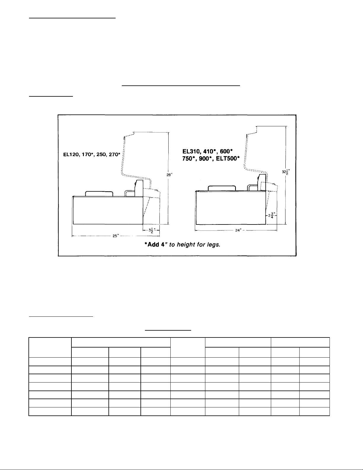
SPECIFICATIONS
Model No. Width Depth Working Ht. Fat Approx.
(inches) (inches) (inches) Capacity (Ibs.) Ship. Wt. (Ibs.)
EL120, 170* 12 1/4 19 1/2 9 1/2 15 29
EL250, 270* 12 1/4 19 1/2 9 1/2 15 29
ELT500* 25 1/2 20 1/2 13 1/2 30 75
EL310, 410* 18 21 11 1/2 20 45
EL600* 18 22 1/2 15 1/2 20 50
EL750* 18 21 1/2 15 1/2 20 54
EL900* 18 21 1/2 15 1/2 20 54
*Add 4" to height for legs to all except EL120, EL250, EL310.
CECILWARE CORPORATION
43-05 20th AVENUE, LONG ISLAND CITY, N.Y. 11105 • 718-932-1414
Page 2
UNPACKING AND INSPECTION:
Carefully lift fryer out of shipping container, and inspect immediately for shipping damage.* On model nos. EL270,
ELT500, EL410, EL600, EL750, and EL900, install 4-inch legs as follows: Remove the legs from plastic shipping
bag, turn fryer on its back and screw legs into the four holes provided in bottom.
*NOTE: Your heavy duty commercial fryer was shipped in a carton designed to give it maximum protection in
normal handling. It was thoroughly inspected before leaving the factory and the carrier accepted and signed for it.
File any claims for shipping damage or irregularities directly with the carrier,
not with the company.
FOR QUALIFIED SERVICE PERSONS ONLY
INSTALLATION: (Caution: Be sure to comply with local codes.)
Carefully place fryer in its permanent location. Allow clearance at rear to allow raising heating elements for cleaning
as shown below:
All fryers must be installed with an approved hood system and fire safety. Check local codes for compliance.
Level fryer after final installation. Height of models with 4 inch legs may be adjusted by turning the legs up or down
as desired.
The fryer is not fused internally; therefore, it must be connected to a fused circuit equipped with a suitable
disconnect as may be required by local electrical code. See Electrical Data table below for the fuse or circuit breaker
required for each fryer.
ELECTRICAL HOOKUP:
ELECTRICAL DATA
Model
EL120, 170 1.8 - - 1 No. 14 - 20A -
EL250, 270 - 5.5 4.2 1 No. 10 - 30A -
ELT500 - 11 8.4 2 No. 6 No. 8 50A 40A
EL310, 410 - 5.5 5.5 1 No. 10 - 30A -
EL600 - 6.6 6.0 3 No. 10 No. 12 30A 20A
EL750 - 7.5 7.5 3 No. 8 No. 10 40A 25A
EL900 - 8.8 8.8 3 No. 6 No. 10 50A 30A
Electrical Rating (KW) Min. Wire Size Fuse
120V 240V 208V
Elements
Required
1 Phase 3 Phase 1 Phase 3 Phase
2
Page 3

ELECTRICAL HOOKUP:
The EL120 is supplied with a standard 120V line cord and requires a 15 amp 120V outlet.
The EL250 and EL270 are both wired with a 240V line cord. Insert line cord into a NEMA-30.5 socket,
wired with a minimum No. 10 wire size.
Hook up the EL310, EL410, EL600, EL750, EL900, and ELT500 as follows:
WARNING
THIS IS HIGH VOLTAGE EQUIPMENT. MAKE SURE MAIN DISCONNECT IS "OFF" BEFORE HOOKING UP
FRYER.
1. Raise heating element(s) and remove fry tank.
2. Take out the screws holding rear inner cover (25, figure 1, or 26, figure 2), and remove inner cover. Main
terminal block (29, figure 1, or 33, figure 2) will be exposed.
3. Refer to field wiring specification label, located near terminal block, or electrical data table on page 2, for proper
wire sizes.
WARNING
MACHINE WARRANTY IS VOID IF FRYER IS CONNECTED TO ANY VOLTAGE OTHER THAN THAT FOR
WHICH IT WAS DESIGNED.
4. Install a suitable conduit through 1 1/4 inch knockout in rear or floor of fryer. For1 phase hookup, connect one
hot wire each to terminals L1 and L2 of terminal block. For 3 phase hookup, connect one hot wire to each of the
three terminals.
5. Connect ground wire (No. 14 min.) to grounding lug (30, figure 1, or 31, figure 2), to comply with local electrical
codes.
6. Models EL750 and EL900 are provided with an auxiliary circuit terminal block, located adjacent to
main terminal block, for connecting an external fire extinguishing system. Make wiring connections
as follows: (Refer to bottom left figure on page 8.)
a. Remove jumper wire between two terminals of auxiliary circuit terminal block.
b. Run 1/2 inch trade size conduit carrying two wires from fire extinguishing system through 7/8 inch knockout
provided in fryer.
c. If fire extinguishing system switch is rated 1 Amp @ 240V, connect directly, as shown in top of figure. If
switch is rated at lower than 240V, or some voltage appears on switch when not connected to fryer, use
relay, as shown in bottom of figure. (Refer to bottom right figure on page 8)
7. On all models, test that all connections are tight; then replace rear inner cover and fry tank. Lower heating
elements into tank.
PREPARING FRYER:
Always use a top grade commercial shortening with a high smoke point and resistance to break down.
RESULTS: Longer fat life and better tasting food.
Pour in shortening up to the fat level line stamped on the rear of fry tank.
VERY IMPORTANT: If solid shortening is used be certain the shortening is PRE -MELTED. If not pack shortening
tightly around heating elements. Set the thermostat dial to 200°F and add shortening until enough is melted to
reach the FAT level line on the rear of the tank.
On Models EL750 and EL900, PRESS "POWER ON" SWITCH before setting the thermostat.
OPERATION:
After shortening is in tank, press power ON switch (EL750, 900 only), set thermostat dial to recommended
temperature and allow fryer to preheat. Amber pilot light will come on during the short preheating period
and go out when preset temperature is reached. You are now ready to start frying.
During frying the heating elements are energized periodically while the thermostat maintains the selected
temperature. Turbulence is created above the heating elements, while the sediment space beneath is
comparatively undisturbed. Fat expansion is approximately 15 % from room temperature to 400° F.
CAUTION: Keep the fat level above the top of the elements at all times. Whenever possible, drain and dry food
before frying. Excessively moist food breaks down shortening, hydrolyzing fat and releasing fatty acids. Such fats
soon begin to smoke and their frying value is greatly diminished.
Load fry baskets uniformly to one half and never more than two-thirds of their capacity. Overloading always results
in an improperly cooked product. Save frying time by lowering baskets into fat immediately after amber pilot light
goes out. At this time fat is at the peak of the temperature cycle.
3
Page 4

Allow foods to cook until done, or leave longer for extra browning. When food is cooked, lift baskets out of fat and
hang them on the basket supports to drain.
During slack periods, turn fryer off or at least reduce thermostat to 200° F. You will get much better mileage out of
your shortening that way.
High Limit Control (24, figures 1 and 2): If, due to a defective thermostat, temperature of fat continues to rise, high
limit control** automatically shuts off heating element(s). When this happens, red pilot light** on control panel
comes on. If high limit control should activate, turn off thermostat and allow fryer to cool. Then press red reset
button** on back of control panel, set thermostat back to desired temperature and resume frying. If high limit cont rol
reactivates, have fryer checked out by a qualified service person.
**The EL600 is equipped with two high limit pilot lights and 1 hi-limit control. The 3 phase model has two high limit
controls.
Tilt Switch: The EL750 and EL900 are equipped with a tilt switch (12, figure 2). This safety feature automatically
shuts off heating elements whenever they are raised. Otherwise, these high wattage elements would quickly
overheat when removed from the fat at high thermostat settings, burning out and/or causing operator injury.
Fuse: The high power EL750 and EL900 fryers are provided with a 6 Amp. fuse for branch circuit protection. (See
diagram on page 8)
MAINTENANCE:
Your fryer was designed to strip down for easy cleaning and maintenance, and has "self cleaning" elements. A
clean fryer performs better, turns out higher quality foods, reduces fat costs, and makes for a safer operation.
CLEANING SUGGESTIONS:
1. Turn off power, remove fry baskets, and wait for fat to cool to a safe handling temperature.
2. Raise heating element(s) to half position to drain for a few minutes; then raise them fully upright until they lock
in place.
3. Carefully remove fry tank(s) (use gloves or pot holders) and drain fat through several layers of cheese cloth
or filters into a clean container.
4. Wash and rinse fry tank(s) and baskets thoroughly. Be sure all traces of soap and water are removed before
placing them back in fryer.
5. Keep all exterior surfaces free of splashed grease and other dirt by washing with hot water and soap. Use
scouring powder and a Scotchbrite pad with the grain for tough blemishes. Do not use steel wool, which will
mar the bright stainless steel finish. Rinse and wipe dry; then polish with a soft cloth.
TO CLEAN HEATING ELEMENTS:
1. All Models except EL750 and EL900: First, wash and rinse visible surfaces of heating element braces;
otherwise they will turn brown and be harder to clean. Then, simply lower elements into operating position in
empty fry tank and set thermostat to 250° F. for a few minutes. When elements stop smoking, turn off
thermostat. Wait for elements to cool; then brush off carbon deposits if necessary. Clean fry tank.
2. EL750 and EL900 only: First, wash and rinse visible surfaces of heating element braces; otherwise they will
turn brown and be harder to clean. Then, simply lower elements into operating position in empty fry tank, press
power ON switch, and set thermostat to 250° F. for a few minutes. When elements stop smoking, turn off
thermostat and power switch. Wait for elements to cool; then brush off carbon deposits if necessary. Clean fry
tank.
Your fryer is now completely clean and ready for the next day's operation.
ADJUSTMENTS
FOR QUALIFIED SERVICE PERSONS ONLY
I High Limit Control Test (EL750, 900 only): To test whether high limit control is working properly, place a
suitable thermometer in fry tank with bulb deeply immersed in hot fat. Pressing Hi Limit Test Switch (35, figure
2) bypasses thermostat, allowing fat to continue to heat up until high limit control is activated. When red Hi
Limit pilot light goes on, note temperature on thermometer (should be between 440° and 475° F). Allow fryer to
cool, then press red reset button(s) on back of control panel. If high limit control does not shut off fryer before
475° F. is reached, have it replaced.
4
Page 5

II Thermostat Adjustment
Problem: Temperature of fat does not appear to coincide with thermostat dial setting, causing improper
frying of foods.
Remedy: Place a suitable thermometer with bulb deeply immersed in the fat. Turn thermostat dial to 375
degrees and carefully remove dial without disturbing setting. To remove dial, grasp knob and pull it
toward you. A small adjusting screw will be visible in center of shaft. When temperature on
thermometer approaches 375° F, slowly turn small adjusting screw in center of shaft clockwise until
temp pilot light on control panel goes out.
NOTE: Turning the screw clockwise lowers the temperature; counterclockwise raises it.
Ill Fryer Not Heating Properly
Problem: Fat does not heat when thermostat is turned "ON" and pilot light does not light (Power
ON switch pressed on EL750, 900).
Possible Causes:
A. High limit control tripped due to high fat temperature.
B. Loss of power to fryer.
C. Thermostat not completing circuit to heaters.
D. Heating element is not in fry tank (EL750, EL900).
E. Fault in auxiliary circuitry (EL750, EL900).
Remedies:
A. Reset high limit control by depressing red button at rear of control panel.
B. Check line fuse or circuit breaker from power source. Replace or reset as necessary.
C. Check thermostat for continuity and wiring to heaters.
D. Lower heating element in fry tank (EL750, EL900).
E. If fire extinguishing system is connected to the fryer (EL750, EL900), check auxiliary circuit and fuse
in control panel. Replace the fuse (SC-6) as necessary.
IV Insufficient Heat
Problem: Thermostat and pilot light are working properly, but there is insufficient heat.
Possible Causes:
A. On 3 phase fryers, fuse in one leg of 3 phase line may be burned out or circ uit breaker tripped.
B. Heating element(s) may be burned out.
Remedy:
A. Replace fuse if needed or reset circuit breaker.
B. Disconnect electrical power from fryer and remove back cover from control panel. Remove element
braces supporting elements(s) and disconnect electrical connections to burned out element(s). Unscrew
mounting nuts from element(s), remove elements, and replace with new ones.
CAUTION: Replacement element(s) must have the same voltage rating as the one(s) removed.
V Hi-Limit Pilot Continue s to Light
Possible Cause: Thermostat out of adjustment or broken.
Remedy: If the thermostat adjustment procedure, as outlined above, does not produce any favorable
results, replace thermostat.
CAUTION: Do not attempt to adjust high limit control. This control was set at the factory and must be replaced
with a new one if it is not operating properly. The high limit control (24, figures 1 and 2) is located in control
panel under the thermostat (except the EL600, which has two high limit control only in control panel) and is
removed in a similar manner (described below).
VI Replacing Thermostat
Remove back cover of control panel. On all fryers except the EL600, thermostat (15, figure 1, or 16, figure 2) is located
in control panel. Disconnect wires and remove mounting screws. On the EL600, lift out fry tank and remove front inner
cover and left wire shield. Take out screws holding thermostat and disconnect wires from terminals. On all fryers,
remove bulb clamps from heating element and pull bulb through rubber grommet in control panel. Install new
thermostat and route capillary tubing the same as old one. Follow adjustment procedure as outlined in Thermostat
Adjustment paragraph above.
NOTE: Before removing thermostat and bulb, note routing of capillary tubing and slack bend areas so that
replacement can be installed in the same manner.
5
Page 6

EL120, EL250, EL270, ELT500 (ELT500 Shown)
Item No. Description EL120 EL250, ELT500
1 Fry Basket, right V091A V091A V091A
Fry Basket, left V092A V092A V092A
2 Fry Tank T044Q T044Q T044Q
3 Tinnerman Cylinder P069A P069A P069A
4 Handle, Heating Element U125A U125A U125A
5 Large Tinnerman Clip P097A P097A P097A
6 Brace, Heating Element U117A U117A U117A
7 Heating Element G039A G042A Q042A
8 Small Tinnerman Clip P096A P096A P096A
9 Rear Wire Shield - - U535A
10 Gasket, Heating Element M079A M079A M079A
11 Red Pilot Light C100A C100A C100A
12 Knob, Thermostat M120A M120A M120A
13 Amber Pilot Light C076A C076A C076A
14 Grommet M039A M039A M039A
15 Thermostat L041A L041A L041A
16 Washer, Heating Element P093A P093A P093A
17 Nut, Heating Element P094A P094A P094A
18 Top Control Box
(less controls) L087Q L087Q L472Q
19 Back Cover T198A T198A T460A
20 Hinge Loop U123A U123A U123A
EL270
REPAIR PARTS LIST
Item No. Description EL120 EL250, ELT500
21 Plug P115A P115A P115A
22 End Piece, right - - U530V
23 Hinge Spring U124A U124A U124A
24 High Limit Control L027A L027A L027A
25 Fire Wall - - T469A
26 Conduit Nipple - - B019A
27 Conduit Nut - - B020A
28 Pivot Bracket - - U532A
29 Terminal Block - - BOOOA
30 Ground Lug - - B039A
31 Body T119Q T119Q T471Q
32 Legs(Set of 4) *M172A *M172A M172A
EL270
End Piece, left - - U531V
Not Shown
Strain Relief B012A B007A Line Cord C185A C208A Rubber Bumper M098A M098A**
6" Hinge U001A U001A *EL270 only
**EL250
*EL170only
-
6
Page 7

REPAIR PARTS LIST
Item No.
Description
EL310,
EL600
ELT500
EL900
Item No.
Description
EL310,
EL600
ELT500
EL900
BOOO
EL310, EL410, EL600, EL750, EL900
(EL750 Shown)
EL410
1 Fry Tank T031Q T031Q T031Q T031Q
2 Fry Basket, Right V077A V077A V077A V077A
Fry Basket, Left V078A V078A V078A V078A
3 Lift Handle, Assy. U122A U117Q U117Q U117Q
4 Outer Element Brace U120A U537A U537A U537A
5 Clamp - U294A U294A U294A
6 Outer Element (240V) - G002A G002A G214A
6 Outer Element (208V) - G002A G214A G214A
7 Inner Element (240V) - G029A G213A G216A
7 Inner Element (208V) - G037A G215A G217A
8 Inner Element Brace U120A U117A U117A U117A
9 Small Tinnerman Clip P096A P096A P096A P096A
Large Tinnerman Clip P097A - - -
10 Red Hi-Limit Pilot
Light C100A C285A C100A C100A
11 Gasket, Heating
Element M097A M097A M097A M097A
12 Tilt Switch - - L325A L325A
13 Knot Thermostat M120A M120A M120A M120A
14 Amber Temp. Pilot
Light C076A - C076A C076A
15 Grommet M039A M039A M039A M039A
16 Thermostat L041A
17 Washer, Heating
Element P093A P260A P260A P260A
18 Nut, Heating Element P094A P259A P259A P259A
19 Top Control Box
(less controls) L129A L153A L329A L329A
20 Hinge Loop U123A U123A U123A U123A
L041A L041A
EL410
21 Back Cover T150A T223A T223A T223A
22 End Piece, Right U268A U268A U268A U268A
End Piece, Left U267A U267A U267A U267A
23 Hinge Spring U124A U124A U124A U124A
24 High Limit Control L027A L027A L027A L027A
25 Rear Wire Shield T184A T184A T184A T184A
26 Inner Cover T221A T221A T221A T221A
27 Conduit Nipple B019A B019A B019A B019A
28 Pivot Bracket U116A U116A U116A U116A
29 Conduit Nut B020A B020A B020A B020A
30 Contactor - - C034A C034A
31 Ground Lug B039A B039A B039A B039A
32 Brody T212Q T219Q T473Q T473Q
33 Terminal Block, Main BOOOA
34 Power On/Off Switch - - L155A L155A
35 High Limit Test
Switch - - L264A L264A
36 Legs (set of 4) M172A* M172A M172A M172A
37 Terminal Block,
Auxiliary Circuit - - L084A L084A
38 Fuse Holder
39 Fuse (SC -6)
Not Shown
Heating Element (240V) G042A - - -
Heating Element (208V) G041A - - -
Thermostat (1 phase) - L072A - -
Thermostat (3 phase) - L073A - -
Rubber Bumper M098A*
B083A B083A
C395A C395A
C908A C908A
—
*EL410 only **EL310 only
7
Page 8

WIRING DIAGRAMS
 Loading...