

2 -Wire Intercom System
CDV96KP User Manual
1
4 5 6
8 9
0 #
7
2 3
*
1
4 5 6
8 9
0 #
7
2 3
*
CDV96KP CDV96KP-SF
CDV-ENG-96/KP-V2

Contents
2. Mounting .............................................................................................................. 1
1. Parts and Functions............................................................................................. 1
3.Terminal Description.. ........................................................................................... 2
9. Specications ..................................................................................................... 17
8. Precautions ......................................................................................................... 17
7. Power Supply Instructions .................................................................................. 17
10.Cable Requirements .......................................................................................... 18
4. System Wiring and Connections ......................................................................... 3
5. Pan,Tilt & Zoom Function .................................................................................... 7
6. Function Setting Up ............................................................................................. 9

-1-
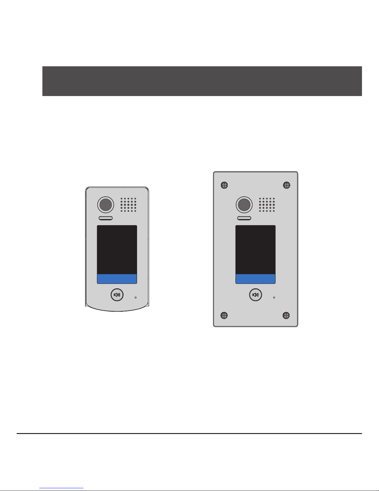
1.Parts and Functions
1
4 5 6
98
0 #
7
2 3
*
Camera Lens
Touch Sensitive
Digital Keypad
Speaker
Nameplate
Call Button
Microphone
93 mm
28 mm
182 mm
1
4 5 6
98
0 #
7
*
2 3
Night Light
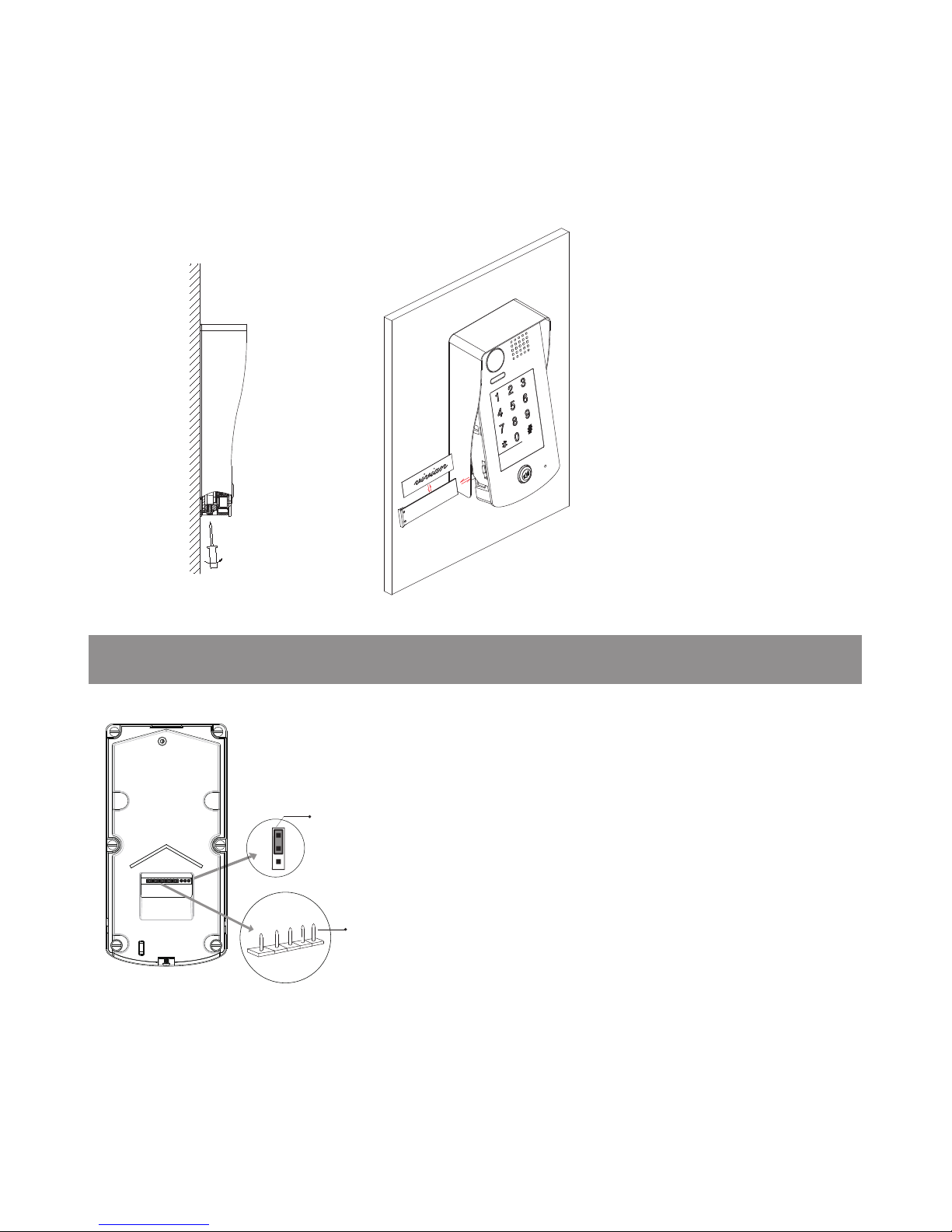
2.Mounting
1 2
43
Connect the cable correctly Drill holes in the wall to match the size of
screws and attach the rain cover to the wall.
CDV96KP Mounting
Rain Cover
CDV96KP
Attach the panel to the rain cover Using a screwdriver attach the keypad to
the rain cover, see diagram above.
-2-
1 2 3
Lock Control Jumper
BUS
PL
S+
S-
Main Connect Port
3.Terminal Descriptions
Placing Name Label
•
Lock Control Jumper:
To select the lock type.
•
Main Connect Port:
To connect the bus line and
the electronic locks.
Using a screwdriver remove the fixing screw, pull forward the panel and slide in the name plate.
•
BUS: Connect to the bus line, no polarity.
• PL: External lock power input.
(if using the external power
supply for the locks, the S- will not be connected).
positive(power +).
• S+: Lock power(+) output.
• S-: Lock power(-) output

-3-
Basic Connection
4.System Wiring and Connections
Electric Lock Connection
Note:
1. Electronic lock of Power-on-to-unlock type should be used.
2. The door lock is limited to 12V, and holding current must be less than 250mA.
3. The door lock control is not timed from Exit Button(EB).
4. The
Unlock Mode
Parameter of Monitor must be set to 0 (by default).
EB
*
LOCK
BUS PL S
+
S-
Jumper position in
Connect one lock
2-3
1 2 3
A fail secure (power applied to unlock) electronic lock device should be used.
BUS(IM) BUS(DS)
PC6
AC~
-
+
L1 L2 PL S+ S-
Doorbell Button
Switch
1 2 3
ON
DIPS

Take off the Jumper
POWER
SUPPLY
BUS PL S+S-
Connect one lock
Door Lock Controlled with Dry Contact
Note:
1. The external power supply must be used according
to the lock.
2. The inside relay contact is restricted to AC or DC
24V/1A.
3. The jumper must be taken off before connecting.
4. Set the
Unlock Mode
of Monitor for different
lock types.
• Power-on-to-unlock type: Unlock Mode=0 (by
default - monitor code 8010)
Note:
1.must connect CDV96KP correctly before setting.
2.the parameter will be saved in CDV96KP automatically,so you need only set on one monitor.
3.the above diagram is t for icon menu series monitors only, to text menu series monitors,please refer to
the corresponding user manual.
• Power-off-to-unlock type: Unlock Mode = 1
- monitor code 8011
Unlock parameter setting(set in monitor)
1.Touch icon on
main menu page.
2.Touch
UNLOCK
button and hold for 2s.
3.A digital keypad will be
shown.
About
Local Address 00.00
Video Standard
AUTO
System Verson 00.01.00
Display Driver 1.0
Front 1.0
UI 1.0
INSTALLER SETUP
123
_
-4-

Multi Door Stations Connection
100~240VAC
DBC4A
A B C D
OFF
ON
Impedance
switch
BUS(IM) BUS(DS)
PC6
AC~
4# Camera
L1 L2 PL S+ S-
(Device Address:3)
3# Camera
L1 L2 PL S+ S-
(Device Address:2)
2# Camera
L1 L2 PL S+ S-
(Device Address:1)
1# Camera
L1 L2 PL S+ S-
(Device Address:0)
Code=15 Code=14
BUS(IM) BUS(DS)
PC6
AC~
100~240VAC
Code=0
1
4 5 6
8 9
0 #
7
2 3
*
(Device Address:0)
Basic IN-OUT(Daisy Chain) Wiring Mode
-5-
 Loading...