

CDVI CDV91S User Manual

English
CDVI 2-Wire Video Outdoor Station
User Manual
ENG-CDV91S-V1 1903

1.Parts and Functions
Camera Lens
LED_UNLOCK
LED_CAM
Speaker
KEY_CALLLED_KEY
Microphone
2.Terminal Descriptions
ON DIP
1 2
ON(1)=OFF(0)
ON
3
ON DIP
1 2
3
4 5
6
L1 L2 LK+ LK-
JP
Lock power (-) output, connect to the power (-) input of lock.
LK-:
4 5
6
L1 L2 LK+ LK-
JP: Lock Control Jumper.
DIP:
Bit 1&2: sets the door station address, a total of 4 door
ON
=
stations can be supported. Please refer to door station
address setting.
Bit 3&4: sets the unlock time for door station. Please refer
to unlock time setting.
Bit 5: sets the unlock mode for door station
(0(OFF):open/1(ON):closed).
Bit 6: 0(OFF)
L1,L2:
LK+:
-1-
> 1(ON), to enter the setting mode.
Connect to the bus line, no polarity.
Lock power(+) output.

3.Mounting
1 2
43
1. Installation height for door station usually is 145~160cm.
2. Use screws to x the back panel to the wall and connect the cables correctly.
3. Attach the front panel to the back panel, then use the screw to secure the panel.
-2-
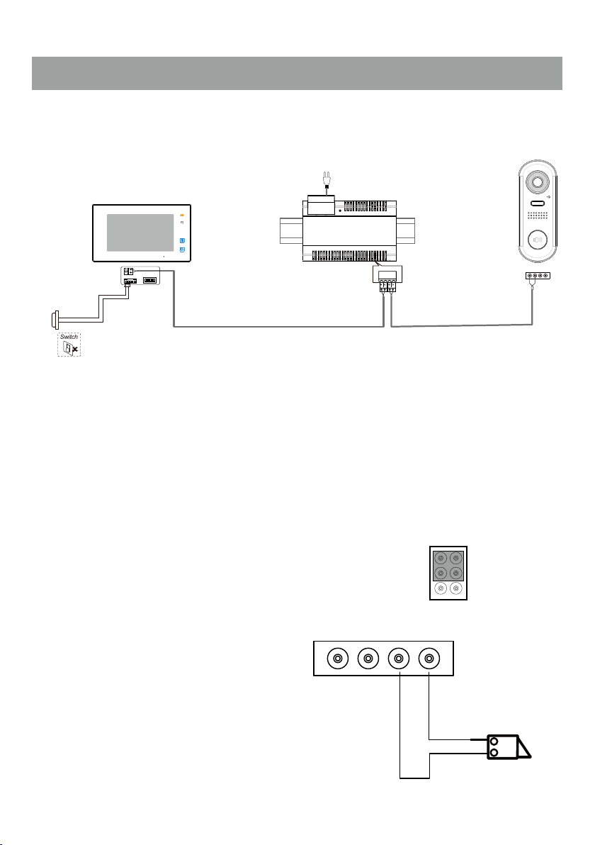
4.System Wiring and Connections
Switch
Basic Connection
Code=00, DIP6=on
AC~
CDV-PC6
L1
L2
DIP Switches
ON DIP
1 2 3 4 5 6
Doorbell Button
Electric Lock Connection
Door Lock Controlled with Internal Power
Note:
1. This mode only supports strike type locks.
2. Strike type locks of Power-on-to-unlock (fail
secure) type should be used.
3. The door lock is limited to 12V, and holding
current must be less than 250mA.
4. The Unlock Mode Parameter of the
Monitor must be set to 0 (default).
BUS(IM) BUS(DS)
JP
Jumper position
L1 L2 LK+ LK-
L1 L2 LK+ LK-
LOCK
-3-

Door Lock Controlled with Dry Contact
Note:
1. An external power supply must be used according
to the lock power requirements.
2. The internal relay contact is restricted to AC or
DC Max 24V/1A.
3. Setup the Unlock Mode of Monitor for different
lock types.
• Power-on-to-unlock (Fail Secure) type:
Unlock Mode=0 (default)
• Power-off-to-unlock (fail safe) type:Unlock Mode=1
Multi Door Stations Connection
JP
Jumper position
L1 L2 LK+ LK-
POWER
SUPPLY
LOCK
4# Camera
(Device Address:3)
3# Camera
(Device Address:2)
2# Camera
(Device Address:1)
OFF
ON
Impedance
switch
A B C D
CDV-DBC4A1
1# Camera
(Device Address:0)
L1 L2 LK+ LK-L1 L2 LK+ LK-L1 L2 LK+ LK-L1 L2 LK+ LK-
AC~
-4-
100~240VAC
CDV-PC6
BUS(IM) BUS(DS)
 Loading...