


The installer’s choice
CDV4791S-DX KIT MANUAL
01628 531300 www.cdvi.co.uk

The installer’s choice
IMPORTANT:
Limitations of this manual: This is provided to allow basic
installation and set up of this kit, for advanced features please
see device manuals included in each product box.
Note: For WiFi Set up please see the CDV47DX manual Pg. 21
1. Kit Contents
2. CDV91S Parts and Functions
2.1: Terminals Description & Dip Switches
2.2: Installation
3. CDV-PC6 Parts and Functions
3.1: Product Description
3.2: Terminals Description
4. CDV47DX Part and Functions
4.1: Terminals & Installation
4.2: Mounting
4.3: Main menu
4.4: Installer Setting
4.5: User Code (Monitor ID) setting
4.6: Unlock Time Setting
4.7: Unlock Mode setting
5. Schematics & Wiring
5.1: Basic Bus Wiring
5.2: Multiple Door Panel Bus Wiring
5.3: Parallel (daisy/In-out) Bus Wiring
5.4: Star Bus Wiring
5.5: Lock Connections
5.6: Cable Requirements
6: Specifications
6.1: CDV91S
6.2: CDV-PC6
6.3: CDV47DX
7: Cable Requirements
1 x CDV91S - 1 or 2 Button Video Entry Panel
1 x CDV-PC6 - Power/Bus Combiner
1 x CDV47DX - TFT Touch screen Internal Monitor
1 x 145mm Din Rail
1 x CDV4791A-DX Kit Manual
1. CDV4791S-DX KIT CONTENTS
1

The installer’s choice
2: CDV91S Parts and Functions
LED_KEY KEY_CALL
Camera Lens
LED_UNLOCK
LED_CAM
Speaker
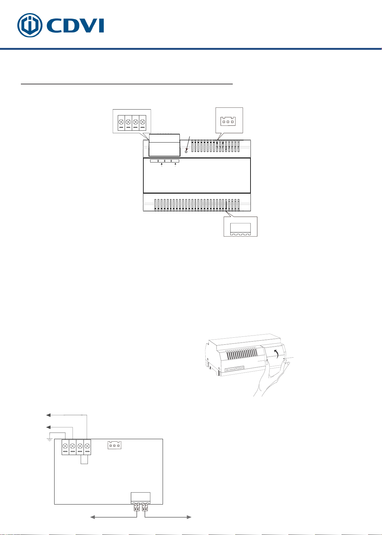
2.1: Terminal Descriptions
ON DIP
1 2
3
4 5
6
L1 L2 LK+ LK-
L1 L2 LK+ LK-
Microphone
DIP:
Bit 1&2: sets the door station address, a total of 4 door
stations can be supported. Please refer to door station
address setting.
ON DIP
1 2
ON(1)=OFF(0)
ON
3
4 5
6
ON
=
Bit 3&4: sets the unlock time for door station. Please refer
to unlock time setting.
Bit 5: sets the unlock mode for door station
(0(OFF):open/1(ON):closed).
Bit 6: 0(OFF)
L1,L2:
Connect to the bus line, no
> 1(ON), to enter the setting mode.
polarity.
Lock power(+) output.
JP
LK+:
Lock power (-) output, connect to the
LK-:
power (-) input of lock.
JP: Lock Control Jumper.
2

The installer’s choice
3: Mounting
1 2
3 4
3: CDV-PC6A Parts and Functions
3.1: Description
The PC6A is a power/bus combiner unit, which is designed for the CDV 2Easy 2 wire
system to supply power for the external station, internal monitor and other accessories
on the bus. It can operate as a normal power/bus combiner or auxiliary PSU. The
features are as follows:
• Universal AC input/full range
• Multi protection: short circuit, overload, over voltage
• Integrated with CDV-DPS (power separator)
• Support up to 4 to 8 monitors (dependent on models)
• DIN Rail Mounting
3
The installer’s choice
LED
CN
1 2 3
BUS(IM) BUS(DS)
N
LPG L
100~240 Vac
PGNL
L
3.2: Terminal Descriptions
AC Input
*
100~240Vac
PG: Earth ground terminal.
N: AC input terminal.
L: AC input terminal.
LED: Power indicator, on when power connected.
CN: Bus control terminal.
BUS(IM): Indoor monitor connection terminal.
BUS(DS): Door station connection terminal.
Open the AC cover:
1. Push the cover base towards
the centre with your fingers;
2. Lift up and pull out the cover.
After connecting the AC cable, it is
advised to replace the cover.
CN
1 2 3
BUS(IM)
BUS(DS)
N
LPG L
Note:
1. The AC cable is not included in the
package, it must comply to the specific
requirements of country where installed.
2. Pins 1&2 should be short-circuited
with a C3-3P link (included in the
package), if the unit operates as a standard
power combiner. If operating as an
auxiliary power combiner, the link should
be removed.
Connect to monitor Connect to door station
4

The installer’s choice
4: CDV47 Parts and Functions
4.1: Terminal description
L1,L2: Bus line terminal.
SW+,SW-: Doorbell input
connection port.
Ring,GND: Extension buzzer input
connection port.
NC: Reserved.
DIP switchesBit1~Bit5: Reserved.
Bit6: Video impedance matching
switch.
Set to ON if the monitor is at the
end of the line or operates with
CDV-DBC4, otherwise, set to
OFF.
4.2: Mounting
Mounting box
(size:86x86mm)
SW-
SW+
L1
L2
GND
RING
NC
ON DIP
1 2 3 4 5 6
DIP Switches
ON DIP
1 2 3 4 5 6
USB-Wi-Fi adaptor
The unit
145~160 cm
2 wire cable
Mounting bracket
Mounting screw
x 2(included)
The installation height is suggested to 145~160cm.
1. Use screws to fasten the mounting bracket to the wall with a standard
single gang ush light switch back box.
2. Connect the 2 wire cables to the unit.
3. Mount the unit to the mounting bracket, make sure the unit is securely
attached to the mounting bracket.
5

The installer’s choice
4.3: Main Menu
Call transfer
The Main menu is your starting point for using all the applications on your monitor.
Touch Unlock button, or touch anywhere of the screen on monitor in standby mode, the
Main menu will appear as follow:
Monitor
Touch to view outdoor scene.
Touch this icon to directly
enable the indicated function.
Current date and time.
Touch to enter the date
time set interface.
Status bar
Light
Touch to trigger an optional
RLC unit to operate the
light function.
Function status
SIP cong
Touch to enter SIP cong
interface.
Wi-Fi status
Touch to enter
Wireless setting
options.
Intercom
Touch to enter intercom
selections.
Call Record
Touch to see calling in/calling
out records or missed calls .
Setting
Press to enter setup interface.
Close
Touch to turn off the screen and
make the monitor in standby
mode.
Call Scene
Touch to activate the functions
of No disturb, Divert call.
Icon Meaning Description
Missed call
No disturb
SIP server connection active
and congured
SIP server connection disabled
SIP server connection active and
not connected
Displayed when there is missed call
Touch to review the missed call in shortcut.
Displayed when the function activated
Touch to enter Call Scene interface in shortcut.
Touch to enter SIP server information interface
in shortcut.
6

The installer’s choice
Icon Meaning Description
Wi-Fi connection active and not
connected
Wi-Fi connection disabled
Touch to enter Wi-Fi setting interface in shortcut.
Wi-Fi connection active and
congured
4.4: Installer Settings
This section contains the device address setting and system settings.
1. Touch to enter installer setting interface.
Setting
Setting
Call Tune
General
Installer
Wireless
About
Current addtess [01]
Intercom enable Enable
IPC Setting
Monitor list manage
System settings
4.5: Users code setting
Touch to set the user code for each monitor.
Setting
Call Tune
General
Installer
Wireless
About
Current addtess [01]
Intercom enable Enable
IPC Setting
Monitor list manage
System settings
1. Enter the code by touching the digital number.
2. Touch "OK" to save the code setting, complete and exit.
Notes: 1. If dip switches 1-5 are set the monitor will show the "Dip switch setting page"
2. A maximum of 32 ID's can be set; 0 to 31.
Current address
26
7

The installer’s choice
4.6: Unlock Time Setting
Setting the unlock time.
Installer Installer
Call Tune
General
Installer
Wireless
About
Current addtess [01]
IPC Setting
Monitor list manage
System settings
FW upgrade
The unlock time can be changed by
yourself at any time. It can be set from
01 to 99 seconds.
Call Tune
General
Installer
Wireless
About
Unlock time
08
Unlock time [03]
Unlock mode [Open]
Auto reboot [Enable]
Reboot
4.7: Unlock Mode Setting
Setting the unlock mode.
Installer Installer
Call Tune
General
Installer
Wireless
About
There are two unlock modes:
1.power-on- to-unlock type = Open
2.power-o-to-unlock = Close.
Current addtess [01]
IPC Setting
Monitor list manage
System settings
FW upgrade
Call Tune
General
Installer
Wireless
About
Installer
Unlock time [03]
Unlock mode [Open]
Auto reboot [Enable]
Reboot
Unlock mode
Open
Close
8

The installer’s choice
Switch
5: System Wiring and Connections
5.1: Basic Connection
Code=00, DIP6=on
AC~
CDV-PC6
L1
L2
DIP Switches
ON DIP
1 2 3 4 5 6
Doorbell Button
5.2: Multi Door Stations Connection
4# Camera
(Device Address:3)
3# Camera
(Device Address:2)
2# Camera
(Device Address:1)
1# Camera
(Device Address:0)
BUS(IM) BUS(DS)
L1 L2 LK+ LK-
L1 L2 LK+ LK- L1 L2 LK+ LK- L1 L2 LK+ LK- L1 L2 LK+ LK-
A B C D
CDV-DBC4A1
OFF
ON
Impedance
switch
AC~
100~240VAC
CDV-PC6
BUS(IM) BUS(DS)
9
The installer’s choice
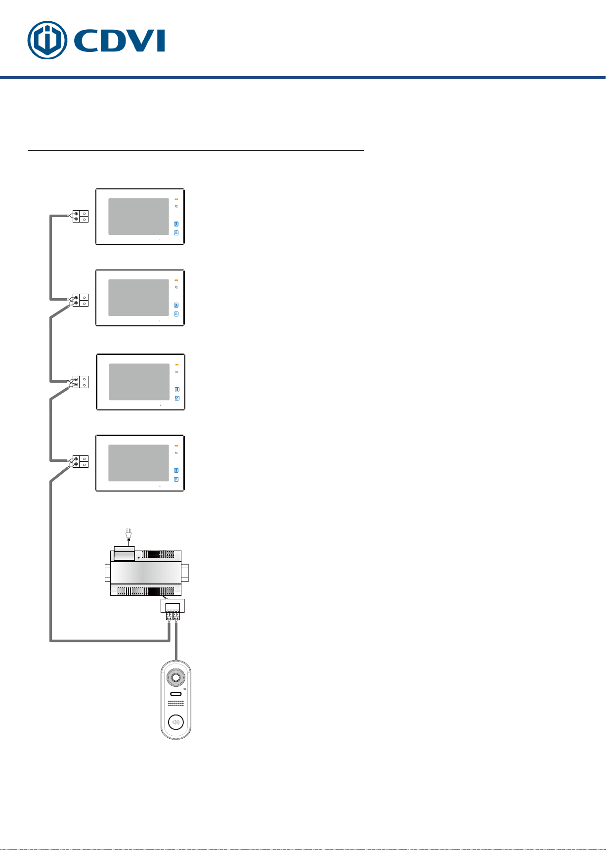
5.3: Basic IN-OUT Wiring in Standard Mode
Code=1, DIP6=on
(Slave 3)
• The door station is compatible with other
monitors within the 2Easy range.
• Please set the door station into group calling
mode if there are more than 4 monitors in villa
(Refer to Page 8).
AC~
100~240VAC
CDV-PC6
Code=1, DIP6=off
(Slave 2)
Code=1, DIP6=off
(Slave 1)
Code=1, DIP6=off
(Master)
• For the last monitor connected to the
system, DIP6 should be set to ON.
BUS(IM) BUS(DS)
ID=0
10
The installer’s choice
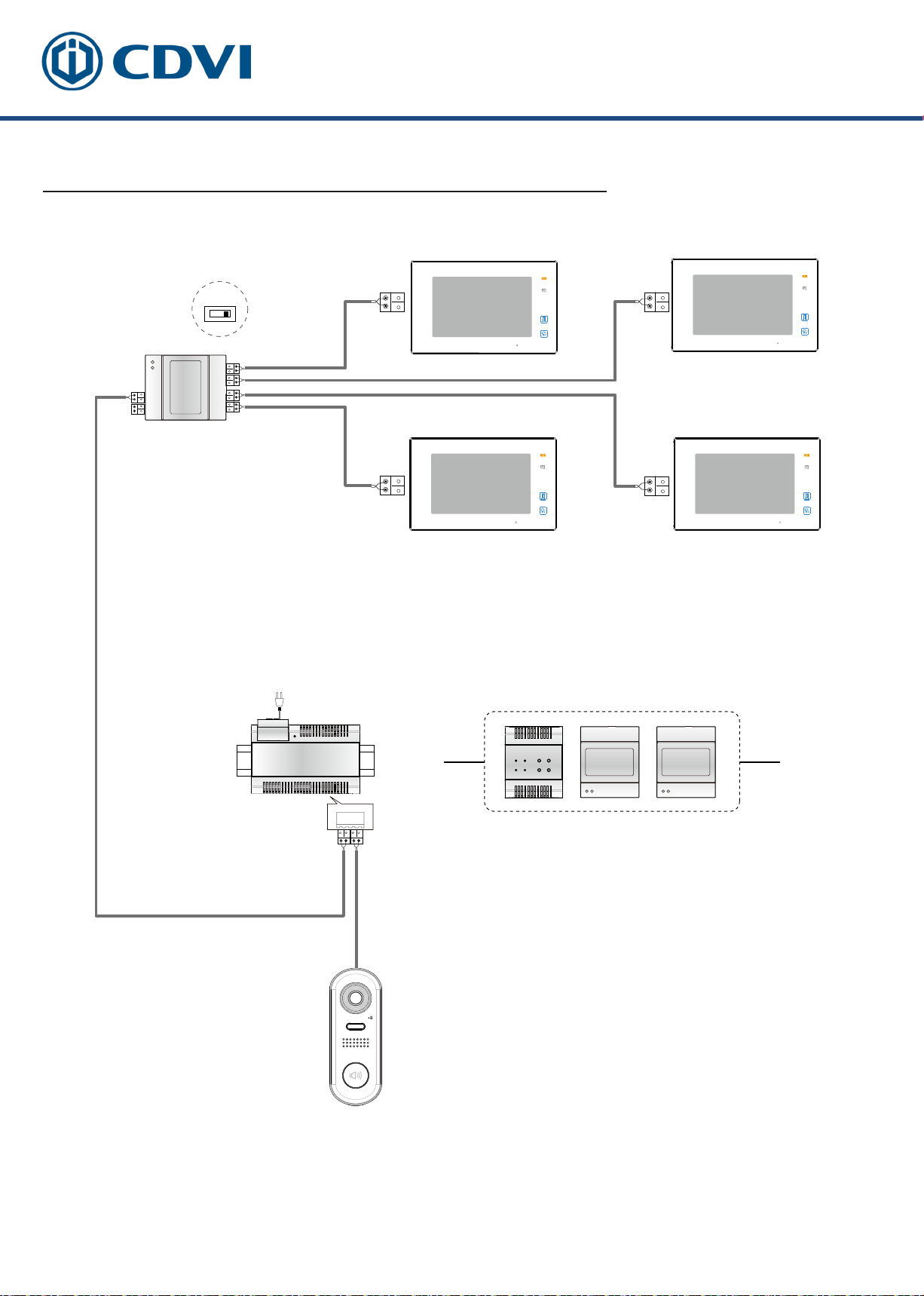
5.4: Star Topology Wiring With CDV-DBC4A1 in Standard Mode
Code=0 Master,DIP6=on Code=0 Slave 1,DIP6=on
Impedance
switch
OFF ON
A B C D
CDV-DBC4A1
Code=0 Slave 2 DIP6=on Code=0 Slave 3,DIP6=on
AC~
100~240VAC
CDV-PC6
BUS(IM) BUS(DS)
CDV-BDU
CDV-RLC CDV-DBC4A1
Optional functional modules:
CDV-BDU bus amplifier module
CDV-RLC staircase light controller module
CDV-DBC4 2/4 inputs branch distributor
ID=0
• The system can be extended by up to 3 slave monitors for each monitor. It is
recommended to use a distributor CDV-DBC4 for the extension.
11
The installer’s choice
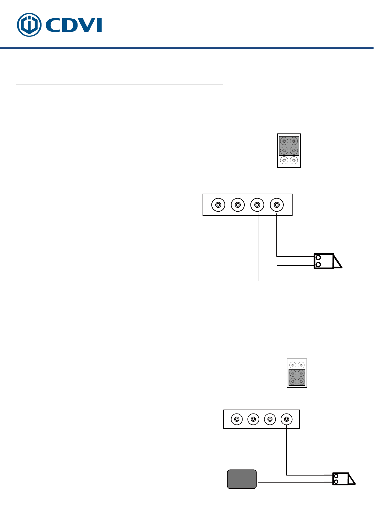
5.5: Electric Lock Connection
Door Lock Controlled with Internal Power
Note:
1. This mode only supports strike type locks.
2. Strike type locks of Power-on-to-unlock (fail
secure) type should be used.
3. The door lock is limited to 12V, and holding
current must be less than 250mA.
4. The Unlock Mode Parameter of the
Monitor must be set to 0 (default).
JP
Jumper position
L1 L2 LK+ LK-
LOCK
Door Lock Controlled with Dry Contact
Note:
1. An external power supply must be used
according to the lock power requirements.
2. The internal relay contact is restricted to AC
or DC Max 24V/1A.
3. Setup the Unlock Mode of Monitor for different
lock types.
• Power-on-to-unlock (Fail Secure) type:
Unlock Mode=0 (default)
• Power-off-to-unlock (fail safe) type:
Unlock Mode=1
JP
Jumper position
L1 L2 LK+ LK-
POWER
SUPPLY
LOCK
12

The installer’s choice
6: Specifications:
6.1: CDV91S Specifications
● Power Supply : DC 24V
● Power Consumption: Standby 14mA; Working status 122mA
● Camera: Color CMOS, 2.0 Mega pixel
● Lock Power supply: 12Vdc, 250mA(Internal power)
● Mounting: Surface mounting
● Working temperature: -15oC to +55oC
1/2.7’’ fisheye camera,1700 wide
angle
● Dimension: 160(H)×60(W)×31.5(D)mm
6.2: CDV-PC6 Specifications
● Input Voltage: 100~240Vac
● Input Frequency: 50~60HzRated
● Output Voltage: DC 28V+2VRated
● Output Current: 1.5A
● Working Temperature -10oC to +50oC
● Input Voltage: Max 230vac, 2A
● Dimension: 140 x 90 x 60mm
6.3: CDV-47DX Specifications
● Power supply: DC 20~28V
● Power consumption: Standby 0.3W; Working 7W
● Monitor screen: 7 Inch digital color TFT
● Display Resolutions: 800*3(R, G, B) x 480 pixels
● Video signal: 1Vp-p, 75Ω, CCIR standard
● Wiring: 2 wires, non-polarity
● Dimension: 132(H)×226(W)×18(D)mm
13

The installer’s choice
7: System Wiring and Connections
The maximum distance of the wiring is limited in the 2Easy system. Using different
cables may also affect the maximum distance which the system can reach.
Basic IN-OUT Wiring Mode
Cable and distance (unit:m)
Cable Usage A B
CDV-PC6
B
Belden 9470 UTP 2x0.75mm
Belden 8471 UTP 2x1mm
2
≤2 IMB≤16 IM
2
60 100 40
80 120 60
A
14

The installer’s choice
Star Topology Wiring Mode With CDV-DBC4
2
CDV-DBC4A1
B
A
2
C
CDV-PC6
Cable and distance (unit:m)
Cable Usage A B C
Belden 9740 UTP 2x0.75mm
Belden 8471 UTP 2x1mm
2
60 60 30
2
80 80 40
15
 Loading...