

Page 1
Twin cavity
dual fuel cooker
PZ 10/2
Before operating this cooker,
please read these instructions carefully
Users Operating Instructions
GB
Page 2

2
Dear Customer
Thank you for choosing one of our appliances, carefully designed and built by our
specialist staff and thoroughly tested to satisfy your cooking requirements.
We suggest that you read this Instruction Booklet so that you will understand fully how
to operate your appliance.
Please keep the booklet handy. You may wish to refer to it at a later date.
CDA
Important:
This appliance is designed and manufactured solely for the cooking of domestic
(household) food and is not suitable for any non domestic application and therefore
should not be used in a commercial environment.
The appliance guarantee will be void if the appliance is used within a non domestic
environment i.e. a semi commercial, commercial or communal environment.
Page 3

3
Contents
Page Number
Introduction . . . . . . . . . . . . . . . . . . . . . . . . . . . . . . . . . . . . . . . . . . . . . . . . . . . . . 4
Features and technical data . . . . . . . . . . . . . . . . . . . . . . . . . . . . . . . . . . . . . . . . . 5
Control panel . . . . . . . . . . . . . . . . . . . . . . . . . . . . . . . . . . . . . . . . . . . . . . . . . . . . 6
Electronic programmer . . . . . . . . . . . . . . . . . . . . . . . . . . . . . . . . . . . . . . . . . . . . . 7
How to use the hob burners . . . . . . . . . . . . . . . . . . . . . . . . . . . . . . . . . . . . . . . 11
How to use the multifunction main oven . . . . . . . . . . . . . . . . . . . . . . . . . . . . . . 14
How to use the conventional oven . . . . . . . . . . . . . . . . . . . . . . . . . . . . . . . . . . 20
Do’s and do not’s . . . . . . . . . . . . . . . . . . . . . . . . . . . . . . . . . . . . . . . . . . . . . . . . 24
Important notes . . . . . . . . . . . . . . . . . . . . . . . . . . . . . . . . . . . . . . . . . . . . . . . . . 25
Care and maintenance . . . . . . . . . . . . . . . . . . . . . . . . . . . . . . . . . . . . . . . . . . . . 26
For the installer
Location . . . . . . . . . . . . . . . . . . . . . . . . . . . . . . . . . . . . . . . . . . . . . . . . . . . . . . . 32
Levelling the cooker . . . . . . . . . . . . . . . . . . . . . . . . . . . . . . . . . . . . . . . . . . . . . . 33
Stability bracket . . . . . . . . . . . . . . . . . . . . . . . . . . . . . . . . . . . . . . . . . . . . . . . . . 35
Provision for ventilation . . . . . . . . . . . . . . . . . . . . . . . . . . . . . . . . . . . . . . . . . . . 36
Gas installation . . . . . . . . . . . . . . . . . . . . . . . . . . . . . . . . . . . . . . . . . . . . . . . . . . 37
Gas connection . . . . . . . . . . . . . . . . . . . . . . . . . . . . . . . . . . . . . . . . . . . . . . . . . 38
Conversion to LPG . . . . . . . . . . . . . . . . . . . . . . . . . . . . . . . . . . . . . . . . . . . . . . . 40
Lubrication of the gas taps . . . . . . . . . . . . . . . . . . . . . . . . . . . . . . . . . . . . . . . . . 42
Electrical installation . . . . . . . . . . . . . . . . . . . . . . . . . . . . . . . . . . . . . . . . . . . . . . 43
Appliance servicing . . . . . . . . . . . . . . . . . . . . . . . . . . . . . . . . . . . . . . . . . . . . . . 45
Guarantee . . . . . . . . . . . . . . . . . . . . . . . . . . . . . . . . . . . . . . . . . . . . . . . . . . . . . . 46
Page 4
4
Introduction
Congratulations on your purchase of this CDA cooker which has been carefully designed
and produced to give you many years of satisfactory use.
Before using this appliance it is essential that the following instructions are carefully read and
fully understood.
We would emphasise that the installation section must be fully complied with for your safety
to ensure that you obtain the maximum benefits from your appliance.
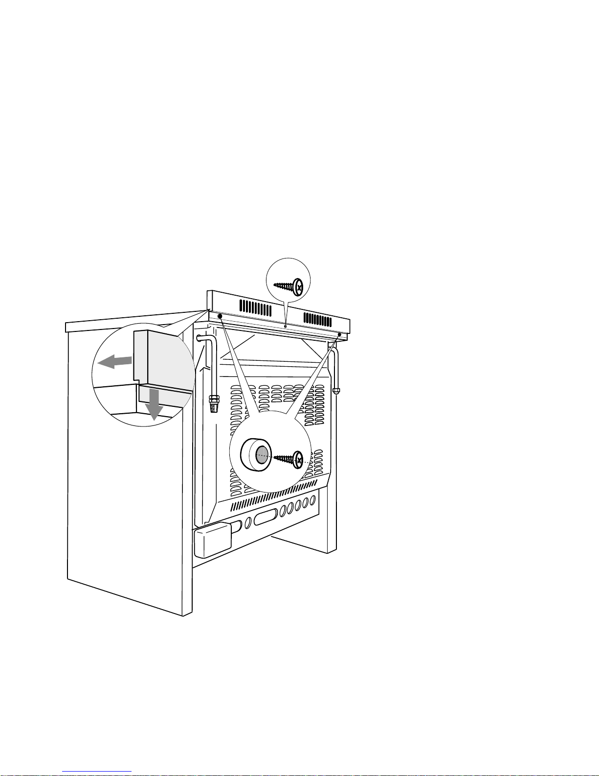
Fig. 1
Assembling the
backguard
■ Remove the two spacers
“A” and the screw “B” from
the rear of the cooktop.
■ Assemble the backguard
as shown in figure 1 and fix
it by screwing the central
screw “B” and the spacers
“A”.
This cooker has been designed, constructed and marketed in compliance with:
- safety requirements of EEC Directive “Gas” 90/396;
- safety requirements of EEC Directive “Low voltage” 73/23;
- protection requirements of EEC Directive “EMC” 89/336;
- requirements of EEC Directive 93/68.
A
B
Page 5
5
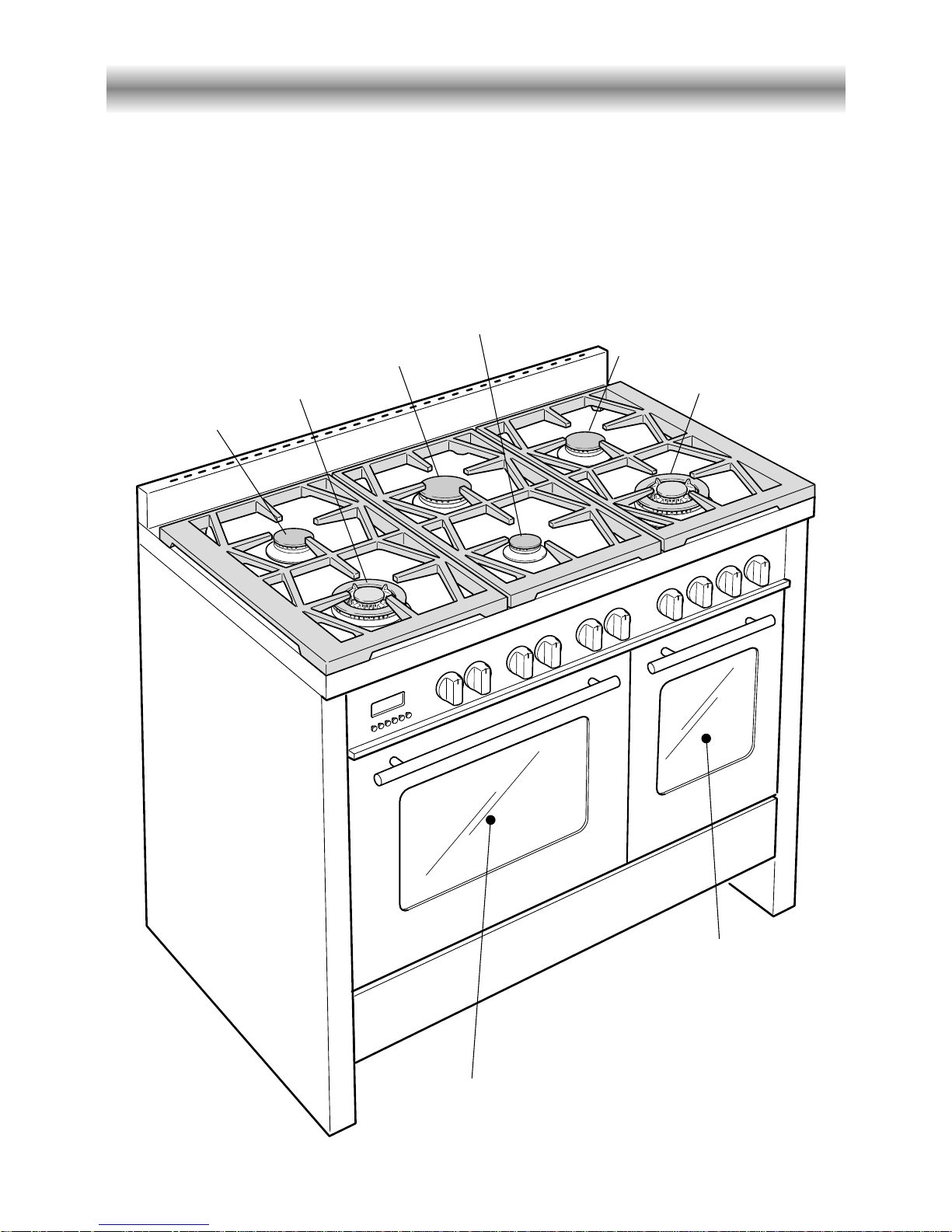
Features and technical data
Fig. 2
2
4
3
4
2
Gas burners
1. Auxiliary burner (A) 1,00 kW
2. Semi-rapid burner (SR) 1,75 kW
3. Rapid burner (R) 3,00 kW
4. Triple-ring burner (TR) 3,50 kW
Multifunction
oven
Conventional
oven
1
Page 6
6
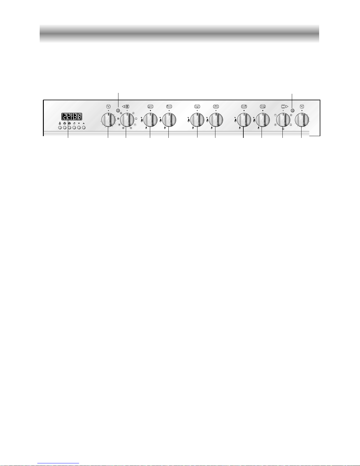
Control panel
Fig. 3
A
U
T
O
225
250
200
175
125
150
75
100
50
225
175
125
75
250
200
150
100
50
98765 1032111
Control panel - Controls description
1. Front right burner control knob
2. Rear right burner control knob
3. Central rear burner control knob
4. Central front burner control knob
5. Rear left burner control knob
6. Front left burner control knob
7. Multifunction main oven switch knob
8. Multifunction main oven thermostat knob
9. Electronic programmer (main oven only)
10. Conventional oven thermostat knob
11. Conventional oven switch knob
Pilot lamps:
12. Main oven thermostat indicator light
13. Conventional oven thermostat indicator light
4
12 13
Please note: This appliance incorporates a safety cooling fan which you will hear
operating whenever the oven or grill are in use. The cooling fan may also operate when
the oven is switched off.
Page 7
7
Electronic programmer (main oven only)
A
U
T
O
Fig. 5
Fig. 4
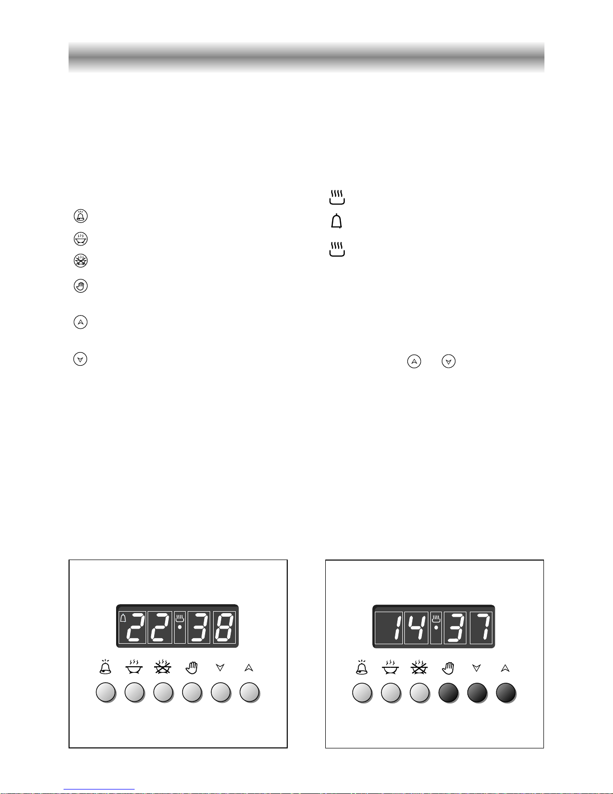
Description of the buttons:
Timer
Cooking time
End of cooking time
Manual position and cancellation of
the inserted cooking programme
Advancement of the numbers of all
programmes
Turning back of the numbers of all
programmes and changing the frequency of the audible signal.
Description of the lighted symbols:
AUTO - flashing - Programmer in auto-
matic position but not programmed
AUTO - always lighted - Programmer in
automatic position with programme inserted.
Automatic cooking taking place
Timer in operation
and AUTO - flashing - Programme
error.
(The time of day lies between the
calculated cooking start and end
time).
Note: Select a function by the respective
button and, in 5 seconds, set the required
time with the / buttons (“onehand” operation).
A power cut zeroes the clock and cancels
the set programmes.
The electronic programmer is a device that groups together the following functions:
– 24 hour clock with illuminated display
– Timer (up to 23 hours and 59 minutes)
– Programme for automatic oven cooking
– Programme for semi-automatic oven cooking.
Page 8
8
Fig. 6
A
U
T
O
Fig. 7
Electronic clock (fig. 5)
The programmer is equipped with an
electronic clock with lighted numbers
which indicate hours and minutes.
Upon immediate connection of the oven
or after a blackout, three zeroes will flash
on the programmer panel.
To set the hour it is necessary to push the
button and then the or button
until you have set the exact hour (fig. 5).
Alternatively, simultaneously push the
two buttons and at the same time
push the or button.
Note: Setting the clock deletes any
programme.
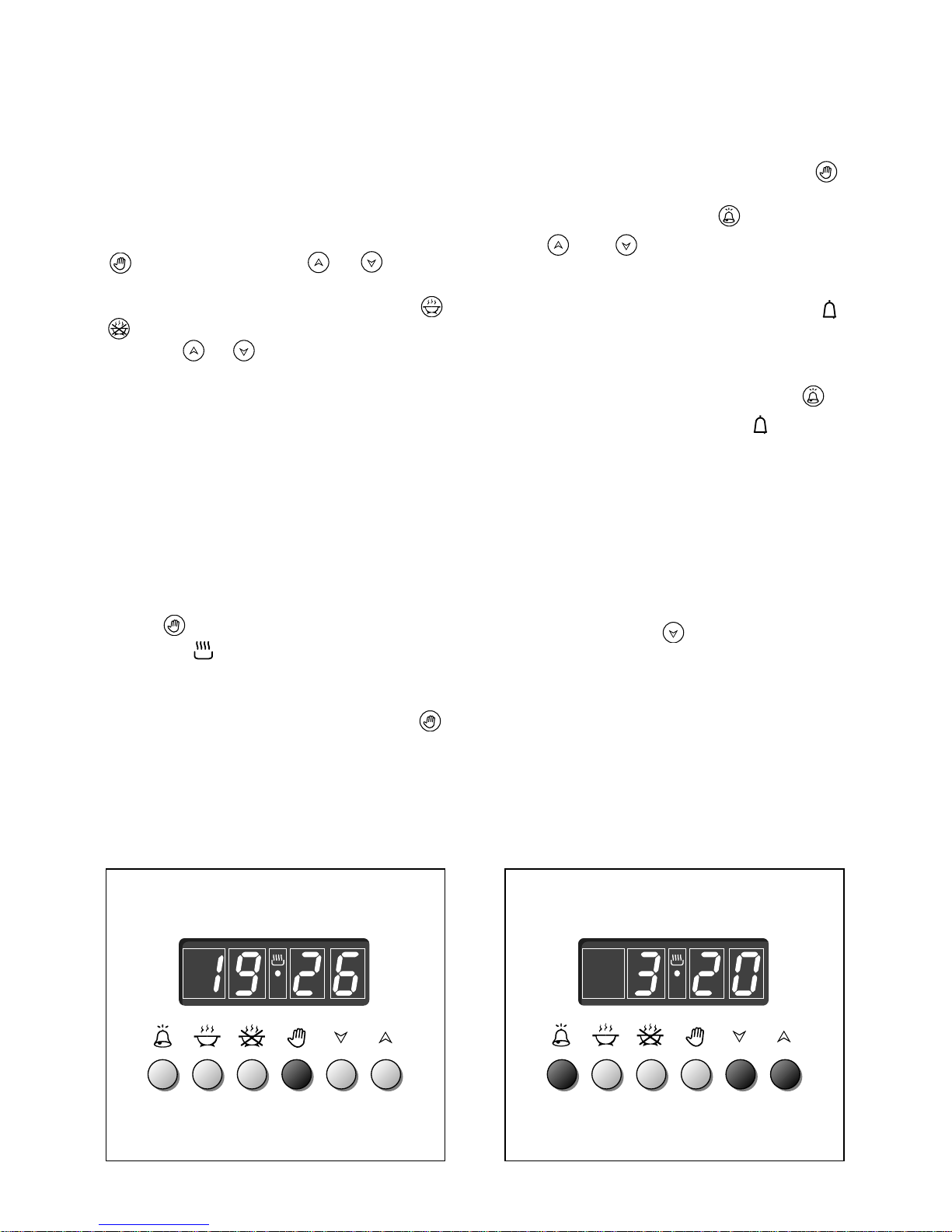
Electronic timer
The timer programme consists only of a
buzzer which may be set for a maximum
period of 23 hours and 59 minutes.
If the AUTO is flashing push the
button.
To set the time, push the button and
the or until you obtain the
desired time (fig. 7).
Having finished the setting, the normal
time will appear on the panel and the
symbol will appear.
The countdown will start immediately
and may be seen at any moment on the
panel by simply pressing the button .
At the end of the time, the symbol
will be switched off and an intermittent
buzzer will go off; this can be stopped
by pressing any one of the buttons.
Altering the audible signal
By pressing the button you can
choose from three variations.
Normal cooking without
the use of the programmer
To manually use the oven, that is, without the
aid of the programmer, it is necessary to
cancel the flashing AUTO by pushing the
button (AUTO will be switched off and
the symbol will go on - Fig. 6).
Attention: If the AUTO is not flashing (which
means a cooking programme has already
been inserted), by pushing the button
you have cancelled the programme and
switched to manual.
Page 9
9
A
U
T
O
A
U
T
O
Fig. 9
Fig. 8
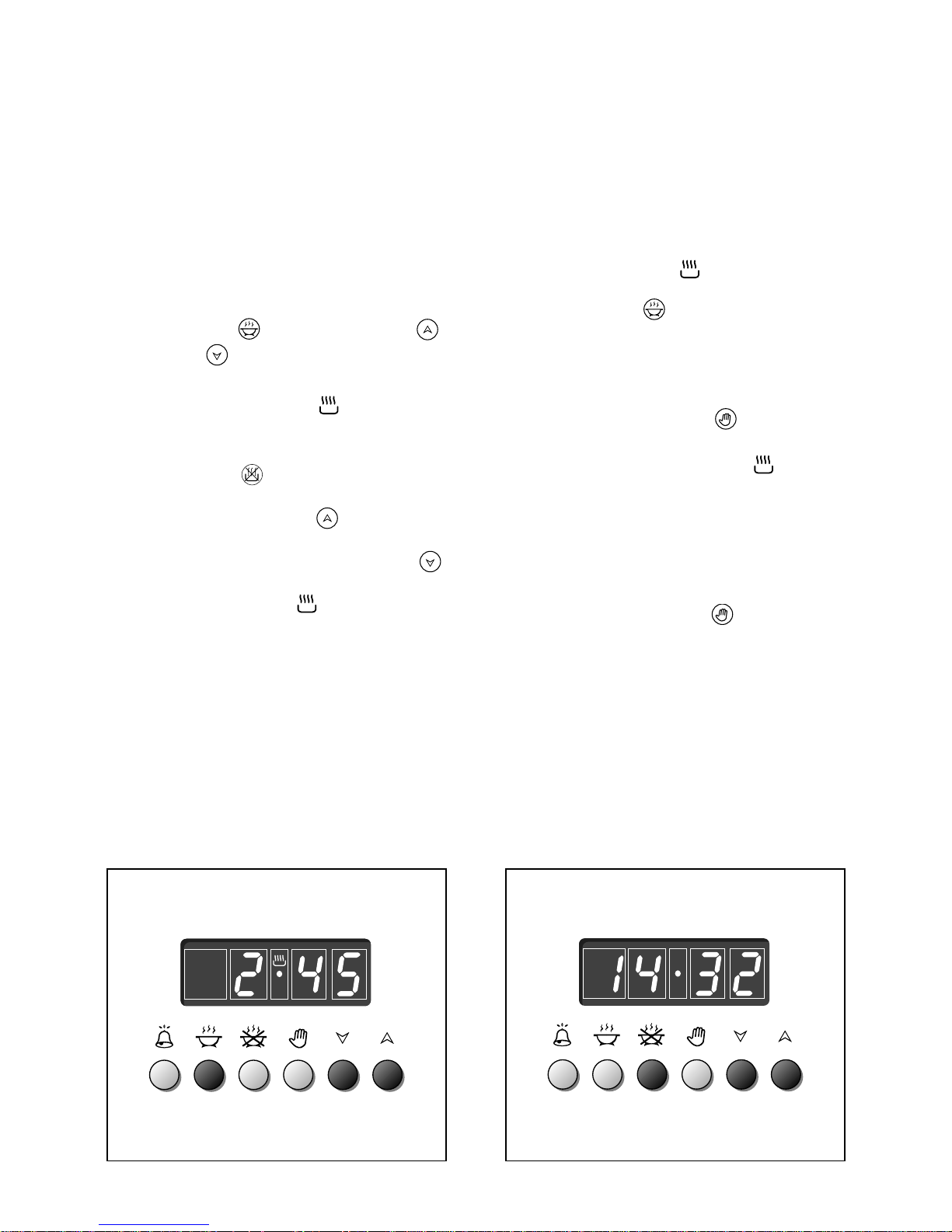
Automatic oven cooking
To cook food automatically in the oven, it
is necessary to:
1. Set the length of the cooking time
2. Set the end of the cooking time
3.Set the temperature and the oven
cooking programme.
These operations are done in the
following way:
1.Set the length of the cooking time by
pushing the button and the
button to
advance, or to go back if
you have passed the desired time (fig.
8). The AUTO and the symbol will
be on.
2.Set the end of the cooking time by
pressing the button (the cooking
time already added to the clock time
will appear), and the button (fig.
9); if you pass the desired time you
may get back by pushing the
button.
After this setting, the symbol will go
off. If after this setting, the AUTO
flashes on the panel and a buzzer goes
off, it means there was an error in the
programming.
In this case, modify the end of cooking
time or the cooking time itself by
following the above instructions again.
3.Set the temperature and the cooking
programme by using the switch and
thermostat knobs of the oven (see
specific chapters).
Now the oven is programmed and everything will work automatically, that is the
oven will turn on at the right moment to
end the cooking at the established time.
During cooking, the symbol remains
on.
By pushing the button you can see
the time that remains until the end of
cooking.
The cooking programme may be cancelled
in any moment by pushing .
At the end of the cooking time the oven
will turn off automatically, the symbol
will turn off, AUTO will flash and a buzzer
will sound, which can be turned off by
pushing any of the buttons.
Turn the switch and thermostat knobs to
zero and put the programmer onto
“manual” by pressing the button.
Attention: A power cut makes the clock
go to zero and cancels the set
programmes.
After a power cut three zeroes will flash
on the panel.
Page 10
10
A
U
T
O
A
U
T
O
Fig. 10
Fig. 11
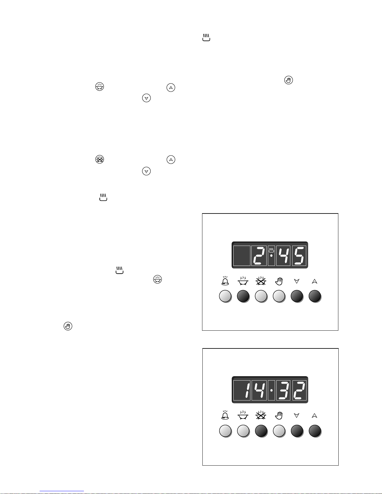
Semi-automatic cooking
This is used to automatically switch off
the oven after the desired cooking time
has elapsed.
There are two ways to set your oven:
1. Set the length of the cooking time by
pushing the button and the
button to advance, or to go
backwards if you have passed the
desired time (Fig. 10).
or
2. Set the end of the cooking time by
pushing the button and the
button to advance, or to go
backwards if you have passed the
desired time (Fig. 11).
AUTO and the symbol will be on.
Then set the temperature and the
cooking programme using the oven
switch and thermostat knobs (see
specific chapters).
The oven is switched on and it will be
switched off automatically at the end of
the desired time.
During cooking, the symbol remains
on and by pressing the button you
can see the time that remains till the
end of the cooking.
The cooking programme can be
cancelled at any moment by pushing
the button.
At the end of cooking, the oven and the
symbol will turn off, the AUTO will
flash and a buzzer will sound; that can be
stopped by pushing any of the buttons.
Turn the switch and thermostat knobs to
zero and put the programmer onto
“manual” by pressing the button.
Page 11
11
How to use the hob burners
Lighting of the hob burners
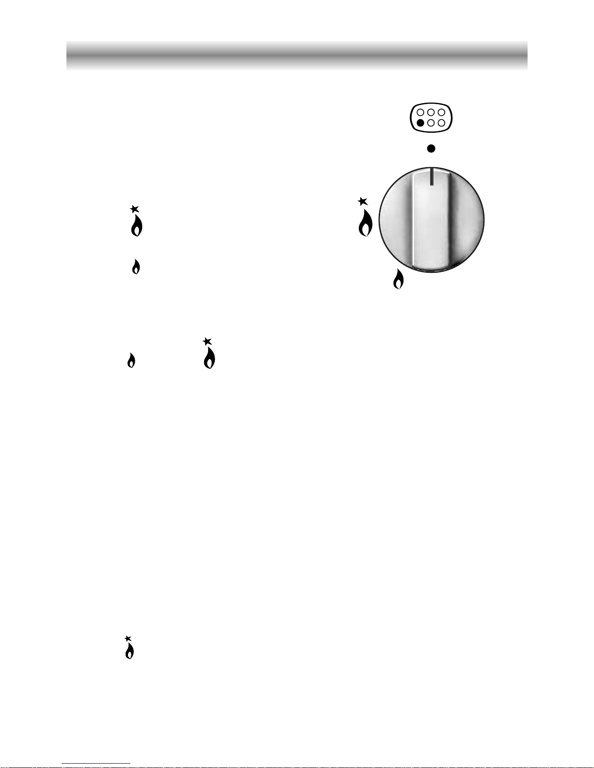
To ignite the burner, the following instructions are to be followed:
1) Lightly press and turn the knob anti-clockwise, and position the knob indicator to the
symbol printed on the control panel (fig. 12).
2) Press the knob to operate the electric ignition; or, in the case of a mains failure light the
burner with a match or lighted taper.
3) Adjust the burner according to the setting required.
Fig. 12
Electric ignition
The sparks generated by the electrodes close to the burners will ignite the chosen
burner. Whenever the lighting of the burners is difficult due to peculiar conditions of
the gas features or supply, it is advised to repeat the ignition with the knob on
“minimum” position.
Hob burners
Each hob burner is controlled by a
separate gas tap operated by a control
knob (fig. 12) which has 3 positions
marked on the control panel, these are:
– Symbol ● : tap closed (burner off)
– Symbol : High (maximum)
– Symbol : Low (minimum)
Push in and turn the knob anti-clockwise
to the selected position.
Low High
To turn the burner off, fully rotate the knob clockwise to the off position: ●.
The maximum setting of the control tap is for boiling, the minimum setting is for slow
cooking and simmering.
All working positions must be chosen between the maximum and minimum setting, never
between the maximum setting and the “OFF” position.
Page 12
12
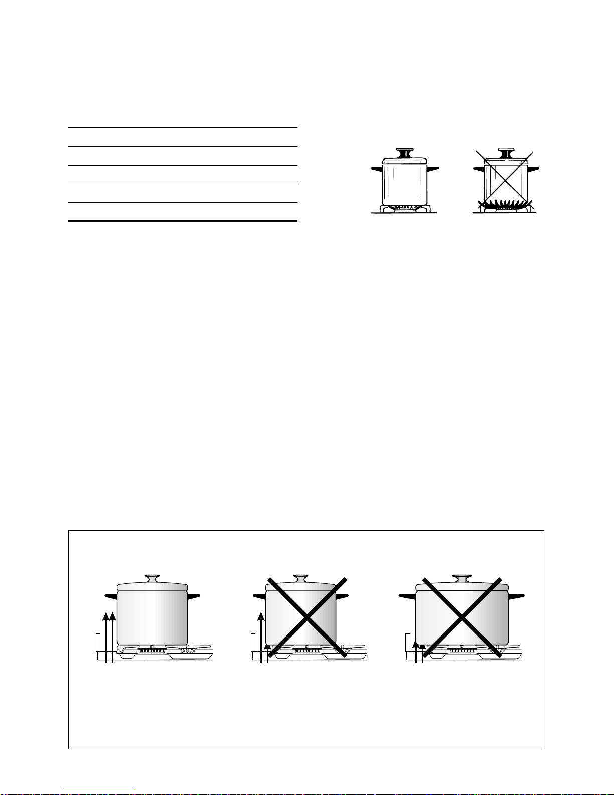
Burners Pan diameter
Auxiliary 12 ÷ 14 cm
Semi-rapid 16 ÷ 24 cm
Rapid 24 ÷ 24 cm
Triple-ring 26 ÷ 28 cm
do not use pans with concave or convex bases
Fig. 13a
Choice of burner
The burner must be chosen according to the diameter of the pans and energy required.
Saucepans with handles that are excessively heavy in relation to the weight of the pan are
less safe as they are more likely to tip.
Pans which are positioned centrally on burners are more stable than those which are offset.
It is far safer to position the pan handles in such a way that they cannot be accidentally
knocked.
When deep fat frying fill the pan only one third full of oil.
DO NOT cover the pan with a lid and DO NOT leave the pan unattended.
In the unfortunate event of a fire, leave the pan where it is and turn off all controls.
Place a damp cloth or correct fitting lid over the pan to smother the flames.
DO NOT use water on the fire.
Leave the pan to cool for at least 30 minutes.
AIR FLOW
(cooling fan)
AIR FLOW
(cooling fan)
AIR FLOW
(cooling fan)
CORRECT USE OF RAPID BURNER
Fig. 13b
Page 13
13
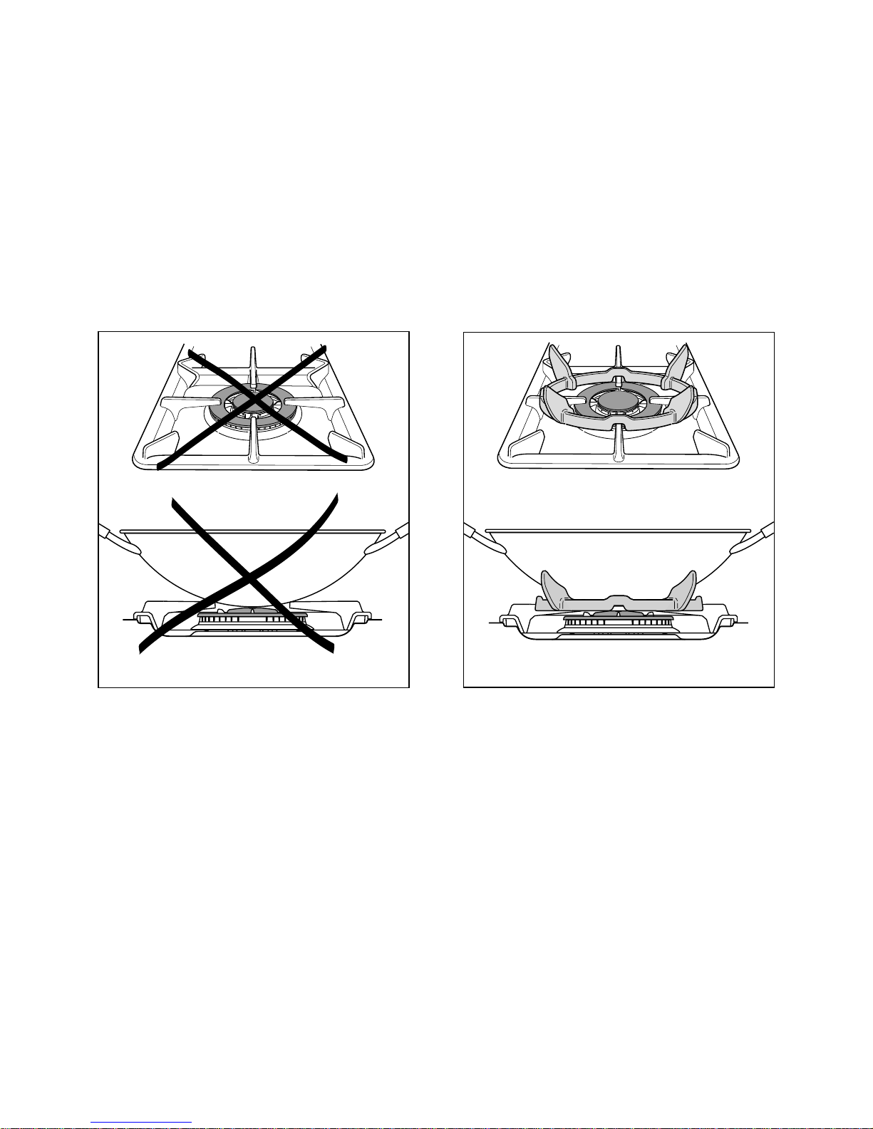
Correct use of triple-ring burner
The flat-bottomed pans are to be placed directly onto the pan-support.
To use the WOK you need to place the proper stand in order to avoid any faulty
operation of the triple-ring burner (Fig. 14a - 14b).
IMPORTANT:
The special grille for wok pans (fig. 14b) MUST BE PLACED ONLY over the pan-rest for the
triple-ring burner.
Fig. 14a
WRONG
Fig. 14b
CORRECT
Page 14
14
How to use the Multifunction main oven
Operating principles
Heating and cooking in the MULTI-FUNCTION oven are obtained in the following ways:
a. by normal convection
The heat is produced by the upper and lower heating elements.
b. by forced convection
A fan sucks in the air contained in the oven muffle, which sends it through the circular
heating element and then sends it back through the muffle. Before the hot air is
sucked back again by the fan to repeat the described cycle, it envelops the food in
the oven, provoking a complete and rapid cooking.
It is possible to cook several dishes simultaneously.
c. by semi-forced convection
The heat produced by the upper and lower heating elements is distributed
throughout the oven by the fan.
d. by radiation
The heat is radiated by the infra red grill element.
e. by radiation and ventilation
The irradiated heat from the infra red grill element is distributed throughout the oven
by the fan.
f. by ventilation
The food is defrosted by using the fan only function without heat.
General features
As its name indicates, this is an oven that presents particular features from an operational
point of view.
In fact, it is possible to insert 7 different programmes to satisfy every cooking need.
The 7 positions, thermostatically controlled, are obtained by 4 heating elements which are:
– Bottom element 1400 W
– Top element 1000 W
– Grill element 2000 W
– Circular element 2500 W
– Fan motor 25 W
– Oven lamp 15 W
Note:
Upon first use, it is advisable to operate the oven for 30 minutes in the position and for another 30 minutes at the maximum temperature (thermostat knob on position 250) in the positions
and
, to eliminate possible traces of grease on the heating elements.
Clean the oven and accessories with warm water and washing-up liquid.
WARNING:
The door is hot, use the handle.
Page 15
15
225
250
200
175
125
150
75
100
50
Function selector knob
(Fig. 16)
Rotate the knob clockwise to set the oven
for one of the following functions.
Thermostat knob
(Fig. 15)
This only sets the cooking temperature
and does not switch the oven on. Rotate
clockwise until the required temperature
is reached (from 50 to 250°C).
Fig. 15
Fig. 16
Oven light
By setting the knob to this position, only the oven light comes on (15 W).
It remains on in all the cooking modes.
Traditional convection cooking
The upper and lower heating elements come on. The heat is dispersed by natural
convection and the temperature must be set to between 50° and 250°C via the
thermostat knob.
The oven must be preheated before cooking.
Recommended for:
Food that requires the same degree of cooking both inside and out, for example roasts,
spare pork ribs, meringues etc.
Page 16

16
Hot air cooking
The circular element and fan come on. The heat is dispersed by forced convection and
the temperature can be regulated to between 50° and 250°C via the thermostat knob.
The oven does not require preheating.
Recommended for:
Food which has to be well-cooked outside and soft or rosy inside, for example
lasagne, lamb, roast beef, whole fish etc.
Defrosting frozen foods
Only the oven fan comes on. Use with the thermostat knob set to “●” - other positions have
no effect. The food is thawed by ventilation without heating.
Recommended for:
Quick thawing of frozen foods; one kg requires approximately 1 hour.
Thawing times vary according to the quantity and type of food to be thawed.
Grilling
The infrared grill element comes on. The heat is dispersed by radiation.
Use with the oven door closed
and the thermostat knob to position 225°C for max 15
minutes, then to position 175°C.
For cooking hints, see the chapter “USE OF THE GRILL”.
Recommended for:
Intense grilling, browning, cooking au gratin and toasting etc.
It is recommended that you do not grill for longer than 30 minutes at any one time.
Caution: the oven door becomes very hot during operation. Keep children well out
of reach.
Page 17

17
Ventilated grill cooking
The infrared grill element and the fan come on. The heat is dispersed mainly by
radiation and the fan then distributes it all over the oven.
Use with the door closed. The temperature can be regulated via the thermostat knob
to between 50° and 175° max.
The oven must be preheated for approximately 5 minutes. For cooking hints, see the
chapter “GRILLING AND AU GRATIN.
Recommended for:
Grilling where quick browning on the outside is required to keep the juices in.
For example: veal steaks, chops, hamburgers etc.
It is recommended that you do not grill for longer than 30 minutes at any one
time.
Caution: the oven door becomes very hot during operation. Keep children well
out of reach.
Maintaining temperature after cooking or slowly
heating foods
The upper heating element, the circular element and the fan come on.
The heat is dispersed by forced convection with greater intensity in the upper part.
The temperature can be set to between 50° and 150°C via the thermostat knob.
Recommended for:
Keeping food warm after any type of cooking. Slow heating of cooked food.
Convection cooking with ventilation
The upper and lower heating elements come on and the fan.
The heat coming from above and below is dispersed by convection with ventilation.
The temperature can be set to between 50° and 250°C via the thermostat knob.
Recommended for:
Voluminous dishes and large quantities which require the same degree of cooking both
inside and out, for example rolled roasts, turkey, roast legs, cakes etc.
Page 18

18
Cooking advice
Sterilization
Sterilization of foods to be conserved, in full and hermetically sealed jars, is done in the following way:
a. Set the switch to position .
b. Set the thermostat knob to position 185 °C and preheat the oven.
c. Fill the dripping pan with hot water.
d. Set the jars onto the dripping pan making sure they do not touch each other and the door
and set the thermostat knob to position 135 °C.
When sterilization has begun, that is, when the contents of the jars start to bubble, turn off
the oven and let cool.
Regeneration
Set the switch to position and the thermostat knob to position 150° C.
Bread becomes fragrant again if wet with a few drops of water and put into the oven for
about 10 minutes at the highest temperature.
Simultaneous cooking of different foods
The MULTI-FUNCTION oven set on position and gives a simultaneous
heterogeneous cooking of different foods. Different foods such as fish, cake and meat
can be cooked together without mixing the smells and flavors together. This is possible
since the fats and vapors are oxidized while passing through the electrical element and
therefore are not deposited onto the foods.
The only precautions to follow are:
– The cooking temperatures of the different foods must be as close to as possible, with
a maximum difference of 20° - 25 °C.
– The introduction of the different dishes in the oven must be done at different times in
relation to the cooking times of each one.
The time and energy saved with this type of cooking is obvious.
Page 19

19
Use of the grill
Preheat the oven for about 5 minutes.
Introduce the food to be cooked, positioning the rack as close to the grill as possible.
The dripping pan should be placed under the rack to catch the cooking juices and
fats.
Grilling with the oven door closed.
Do not grill for longer than 30 minutes at any one time.
Caution: the oven door becomes very hot during operation. Keep children well
out of reach.
Roasting
To obtain classical roasting, it is necessary to remember:
– that it is advisable to maintain a temperature between 180° and 200 °C.
– that the cooking time depends on the quantity and the type of foods.
Grilling and “au gratin”
Grilling may be done without the roasting jack on position of the switch, because
the hot air completely envelops the food that is to be cooked.
Set the thermostat to position 175 °C and after having preheated the oven, simply place
the food on the rack.
Close the door and let the oven operate with the thermostat on position 175 °C, until
grilling is done.
Adding a few dabs of butter before the end of the cooking time gives the golden “au
gratin” effect.
It is recommended that you do not grill for longer than 30 minutes at any one
time.
Caution: the oven door becomes very hot during operation. Keep children well
out of reach.
Page 20

20
225
175
125
75
250
200
150
100
50
Fig. 17 Fig. 18
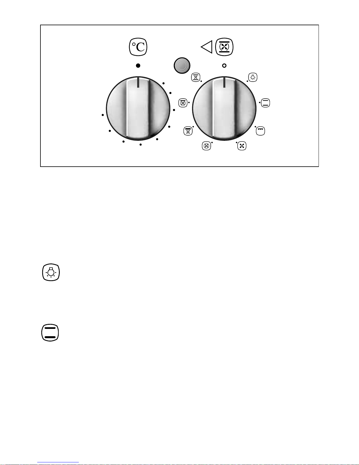
How to use the Conventional oven
General features
As its name indicates, this is an oven that presents particular features from an operational
point of view.
The conventional oven is provided with 3 heating elements which are:
– Bottom element 800 W
– Top element 700 W
– Grill element 1450 W
Note:
Upon first use, it is advisable to operate the oven at the maximum temperature (thermostat
knob on position 250) for 60 minutes in the position and for another 15 minutes in the
position to eliminate possible traces of grease on the heating elements.
WARNING:
The door is hot, use the handle.
Function selector knob (Fig. 17)
Rotate the knob clockwise to set the oven for one of the following functions.
Thermostat knob (Fig. 18)
This only sets the cooking temperature and does not switch the oven on.
Rotate clockwise until the required temperature is reached (from 50 to 250°C).
The light above the function selector will illuminate when the oven is switched on and turns
off when the oven reaches the correct temperature.
The light will cycle on and off during cooking in line with the oven temperature.
Page 21

21
Oven light
By setting the knob to this position, only the oven light comes on (15 W).
It remains on in all the cooking modes.
Traditional convection cooking
or plate warming
The upper and lower heating elements come on. The heat is dispersed by natural convection.
Traditional convection cooking:
The temperature must be set to between 50° and 250°C via the thermostat knob. The oven
must be preheated before cooking.
In the position the rotisserie motor comes on for cooking with the rotisserie.
Recommended for:
Food that requires the same degree of cooking both inside and out, for example roasts,
spare pork ribs, meringues etc.
Plate warming:
Set the position and the temperature to about 60°C via the thermostat knob.
Ideal for:
Dish warming using the special rack. For correct use see the chapter “USE OF SPECIAL DISH
RACK”.
Traditional grilling
The infrared electrical resistance comes on.
The heat is diffused by radiation.
Use with the oven door closed
and the thermostat knob to position 225°C for 15 minutes
then to 175°C.
In the position the rotisserie motor comes on for cooking with the rotisserie.
For cooking hints, see the chapter “USE OF THE GRILL”.
Recommended for:
Intense grilling, browning, cooking au gratin and toasting etc.
It is recommended that you do not grill for longer than 30 minutes at any one time.
Attention: the oven door becomes very hot during operation.
Keep children away.
Page 22

22
Use of the rotisserie
– Insert the dripping pan into the lowest rack holders of the oven and insert the rod support
into the intermediate rack holders.
– Put the meat to be cooked onto the rod, being careful to secure it in the center with the
special forks.
– Insert the rod into the motor opening and rest it onto the support of the spit collar; then
remove the grip by turning it to the left.
Fig. 19
Use of the grill
Switch the grill on, setting the two knobs:
– Function selector to or position.
– Thermostat selector to position 225°C for 15 minutes then to 175°C.
Leave to warm up for approximately 5 minutes with the door closed
.
Place the food inside positioning the rack as near as possible to the grill.
Insert the drip pan under the rack to collect the cooking juices.
Grilling with the oven door closed and do not for longer than 30 minutes at any one
time.
Attention: the oven door becomes very hot during operation.
Keep children away.
Rotisserie
The oven is equipped with a rotisserie.
This device is made up of:
– an electrical motor mounted on the rear part of the oven
– a stainless steel rod, equipped with a detachable athermic handle and 2 adjustable forks
– a rod support to be inserted into the central rack holders of the oven.
The rotation direction of the rotisserie can
be either clockwise or counter-clockwise.
Page 23

23
Use of special dish rack
This special shelf can be used as dish rack or turning over, as normal shelf for oven cooking.
It must be inserted between the guides of the lateral racks.
Using the special shelf as a dish rack
Slide in the shelf on the guides, on the lower level of the lateral racks.
The prongs where the plates are to be inserted, must be turned upwards.
The shelf must be fitted so that the safety catch, which stops it sliding out, faces the bottom
of the oven (see detail of figure 20).
The plates must be positioned as indicated in figure 20.
To facilitate this operation, pull the special rack up to the safety lock.
KEEP ATTENTION: Plates are hot after warming. It is advisable to handle the plates
using oven gloves.
Using the special rack for normal cooking
Slide in the shelf on the guides: the safety catch must be turned toward the oven base (see
detail of figure 21).
The flat surface can be used to put cooking pans or food directly on the rack - the dripping
pan should be placed under the rack to catch the cooking juices and fats.
Fig. 20
Fig. 21
Page 24

24
Do’s and do not’s
Do’s and do not’s
• Do always grill with the oven door closed.
• Do read the user instructions carefully before using the cooker for the first time.
• Do allow the oven to heat for one and a half hours, before using for the first time, in order
to expel any smell from the new oven insulation, without the introduction of food.
• Do clean your oven regularly.
• Do remove spills as soon as they occur.
• Do always use oven gloves when removing food shelves and trays from the oven.
• Do not allow children near the cooker when in use.
• Do not allow fat or oils to build up in the oven trays, or oven base.
• Do not place cooking utensils, plates or any other item directly onto the oven base.
• Do not grill food containing fat without using the grid.
• Do not cover the grilling grid with aluminium-foil.
• Do not use the oven tray for roasting.
• Do not place hot enamel parts in water. Leave them to cool first.
• Do not allow vinegar, coffee, milk, saltwater, lemon or tomato juice to remain in contact
with enamel parts (inside the oven and on the oven tray).
• Do not use abrasive cleaners or powders that will scratch the surface of the stainless steel
and the enamel.
• Do not attempt to repair the internal workings of your cooker.
• Do remove the protective film before the first use.
• Fire risk! Do not store flammable material in the oven and in the drawer.
For your safety
The product should only be used for its intended purpose which is for the cooking of
domestic foodstuffs.
Under no circumstances should any external covers be removed for servicing or
maintenance except by suitably qualified personnel.
Page 25

25
Important notes
Installation, and any demonstration, information or adjustments are not included in the
warranty.
The cooker must be installed by a qualified person in accordance with the Gas Safety
(Installation and Use) (Amendment) Regulations 1990 and the relevant building/l.E.E
Regulations.
Failure to install the appliance correctly could invalidate any manufacturers warranty and
lead to prosecution under the above quoted regulation.
In the UK C.O.R.G.I registered installers are authorised to undertake the installation and
service work in compliance with the above regulations.
Attention
The appliance gets very hot, mainly around the cooking areas. It is very important
that children are not left alone in the kitchen when you are cooking.
Page 26

26
Cleaning the hob
Spillage on the hob can usually be removed by a damp soapy cloth. More obstinate stains
can be removed by rubbing gently with a soapy nylon (non metal) scouring pad or mild
household cleaner.
Important:
As a safety measure, before you start cleaning the cooker be sure to disconnect it from the
mains supply.
Do not use a steam cleaner because the moisture can get into the appliance thus
make it unsafe.
Care and maintenance
Gas taps
If a tap becomes stiff, do not force; contact your local Service Centre.
Flexible tube
From time to time, check the flexible tube connecting the gas supply to the cooker.
It must be always in perfect condition; in case of damage arrange for it to be replaced by a
C.O.R.G.I. registered installer.
Cleaning oven parts after use
The oven interior and the chromium plated shelves can be cleaned by damp soapy cloth.
Obstinate stains can be removed with nylon scouring pads and gentle, non-abrasive, liquid
cleaner. Provided the oven is wiped over immediately after roasting, only the minimum of
cleaning should be necessary.
Stainless steel surfaces
The stainless steel front panels on this cooker (facia, oven door, drawer) are protected by a
finger-print proof lacquer. To avoid damaging this lacquer, do not clean the stainless steel
with abrasive cleaners or abrasive cloths or scouring pads.
ONLY SOAP/WARM WATER MUST BE USED TO CLEAN THE STAINLESS STEEL SURFACES.
Page 27

27
Burners
They can be removed and washed only with soapy
water.
Detergents can be used but must not be abrasive or
corrosive.
Do not use abrasive sponges or pads.
Do not put in dishwasher.
After each cleaning, make sure that the burnercaps, as well as the burners, have been well
wiped off and CORRECTLY POSITIONED.
It is essential to check that the burner flame
distributor F and the cap C has been correctly
positioned (see fig. 22) - failure to do so can
cause serious problems.
Check that the electrode “S” (fig. 22) is always
clean to ensure trouble-free sparking.
Note:
The electrode “S” must be very carefully
cleaned.
To avoid damage to the electric ignition do
not use it when the burners are not in place.
F
S
C
Triple ring burner
The triple ring burner must be correctly positioned (see figs. 23-24); the burner rib must be
located correctly in the burner base as shown by the arrow.
The burner correctly positioned must not rotate (fig. 24).
Then position the cap A and the ring B (fig. 24).
A
Fig. 22
Fig. 23 Fig. 24
B
Page 28

28
Cast-iron pan-supports
The pan-supports must be correctly positioned as shown in the figure 25.
DO NOT place the pan-supports as shown in the figure 26.
WRONG
CORRECT
small edge
big edge
Fig. 25
Fig. 26
Page 29

29
Drawer
– The drawer (fig. 28) comes out like a normal drawer.
Attention: Do not store flammable material in the oven, or in the drawer.
Fig. 27
Fig. 28
Removal of the inner glass door panel
– The inner glass door panel can easily be removed for cleaning by unscrewing the
four screws (fig. 27).
– When re-assembling ensure that the inner glass is correctly positioned and do not
over tighten the screws.
Page 30

30
Changing the oven light
1. Disconnect the electrical power supply (for example, by switching off the main power
switch).
2. Unscrew the light cover
3. Fit a new bulb.
4. Refit the cover.
Note:
Use only bulbs designed to resist up to 300°C with the following characteristics: 15 W,
230 V, type E-14.
Assembling and
dismantling of the side
runner frames
– Fit the side runner frames into the holes
on the side walls inside the oven
(Fig. 29).
– Slide the tray and rack into the runners
(Fig. 20).
– To dismantle, operate in reverse order.
Fig. 29
Fig. 30
Inside of oven
This must be cleaned regularly.
Remove and refit the side runner frames
as described in the next chapter.
With the oven warm, wipe the inside
walls with a cloth soaked in very hot
soapy water or another suitable product.
Side runner frames, tray and rack can be
removed and washed in the sink.
Page 31

31
Door assembly
● Grip the door (as indicated in
figure 31) and refit it in reverse order
of removing procedure.
Removing the oven door
Please operate as follows:
● Open the door completely.
● The swivel retainers of the rh and lh
hinges (fig. 31a) are hooked onto the
metal bar above them (fig. 31b).
● Lift the oven door slightly. The notch
on the bottom of the hinge will
disengage (fig. 31c).
● Now pull the oven door forwards off
the appliance. Release both hinge
sections from the slots (fig. 31d).
Fig. 31
Fig. 31a
Fig. 31b
Fig. 31c
Fig. 31d
Page 32

32
FOR THE INSTALLER
Location
This cooker has class “2/1” overheating protection so that it can be installed next to
a cabinet.
If the cooker is installed adjacent to furniture which is higher than the gas hob cooktop, a
gap of at least 200 mm must be left between the side of the cooker and the furniture.
The furniture walls adjacent to the cooker must be made of material resistant to heat.
The veneered synthetic material and the glue used must be resistant to a temperature of
90°C in order to avoid ungluing or deformations.
The cooker may be located in a kitchen, a kitchen/diner or bed-sitting room but not in a
room containing a bath or shower.
Curtains must not be fitted immediately behind appliance or within 500 mm of the sides.
It is essential that the cooker is positioned as stated below.
The cooker must be installed by a qualified technician and in compliance with
local safety standards.
If the cooker is located on a pedestal it is necessary to provide safety measures to prevent
falling out.
500 mm
450 mm
200 mm
air vent
650 mm
Fig. 32
Page 33

33
Levelling the cooker
Fig. 33
+ 8 mm
+ 8
0
mm
+ 35 mm
Fig. 34a
Fig. 34b
The cooker is equipped with 4 LEVELLING
FEET and may be levelled by screwing or
unscrewing the feet with a spanner (fig. 33).
It is important to obser
ve the prescriptions
of figures 34a - 34b.
Page 34

34
Moving the cooker
Warning
When raising cooker to upright position always ensure two people carry
out this manoeuvre to prevent damage to the adjustable feet (fig. 35).
Warning
Be carefull: do not lift the cooker by
the door handle when raising to the
upright position (fig. 36).
Warning
When moving cooker to its final position
DO
NOT DRAG (fig. 37).
Lift feet clear of floor (fig. 35).
Fig. 35
Fig. 36
Fig. 37
Page 35

35
Fig. 38
Stability bracket
We recommend a stability bracket is fitted to the cooker.
The type shown in fig. 38 can be purchased from most plumbers merchants and do it
yourself (D.I.Y.) shops.
Wall fixing
Floor fixing
Brackets
Existing
slot in rear
of cooker
Dotted line showing the
position of cooker when fixed
Dimension is in millimetres
3
Outline of cooker
backplate at the
engagement slot
Page 36

36
Provision for ventilation
The room containing the cooker should have an air supply in accordance with BS.5540: Part
2: 1989.
All rooms require an openable window or equivalent while some rooms require a
permanent vent in addition to the openable window.
The cooker should not be installed in a bed-sitting room, of volume less than 21 m
3
.
Where a DOMESTIC COOKER is installed in a room or internal space, that room or internal
space shall be provided with a permanent opening which communicates directly with
outside air and is sized in accordance with table below. In domestic premises the
permanent opening shall be an air vent.
If there are other fuel burning appliances in the same room, BS.5540: Part 2: 1989 should be
consulted to determine the requisite air vent requirements.
If the cooker is installed in a cellar or basement, it is advisable to provide an air vent of
effective area 100 cm
2
, irrespective of the room volume.
(❊) If the room or internal space containing these appliances has a door which opens
directly to outside, no permanent opening is required.
MINIMUM PERMANENT OPENING FREE AREA FOR FLUELESS APPLIANCE
5 m3to 10
m
3
Openable
window or
equivalent also
required
Maximum
appliance
rated input
limit
Room volume
11 m3to
20 m
3
> 20 m
3
< 5 m
3
Type of appliance
Domestic oven, hotplate,
grill or any combination
thereof.
None
50 (❊)
cm
2
Nil
cm
2
Nil
cm
2
100
cm
2
Yes
Page 37

37
Gas installation
Important note
This appliance is supplied for use on NATURAL GAS only and cannot be used on any other
gas without modification.
This appliance is manufactured for conversion to LPG and is supplied with a conversion kit.
The cooker must be installed by a qualified person in accordance with the Gas Safety
(Installation and Use) (Amendment) Regulation 1990 and the relevant building/l.E.E.
Regulations.
The following British Standards should be used as reference when installing this appliance.
BS6172 1990, BS5440 part 2 1989 and BS6891 1988.
Failure to install the appliance correctly could invalidate any manufacturers warranty and
lead to prosecution under the above quoted regulation.
In the UK C.O.R.G.I registered installers are authorised to undertake the installation and
service work in compliance with the above regulations.
Page 38

38
Gas connection
The installation of the cooker to Natural Gas or LP Gas must be carried out by a qualified gas
engineer. Installer shall take due account of the provisions of the relevant British Standards
Code of Practice, the Gas Safety Regulations and the Building Standards (Scotland)
(Consolidation) Regulations issued by the Scottish Development Department.
Installation to Natural Gas
Installation to Natural Gas must conform to the Code of Practice, etc. The supply pressure
for Natural Gas is 20 mbar.
Installation to LP Gas
This appliance must only be connected to LPG after an LPG conversion kit has been fitted,
(see pages from 40 to 42).
When operating on Butane gas a supply pressure of 28-30 mbar is required.
When using Propane gas a supply pressure of 37 mbar is required.
The installation must conform to the relevant British Standards.
Warning: Only a qualified gas engineer, also with technical knowledge of electricity should
install the cooker. He should observe the Regulations and Codes of Practice governing such
installation of gas cookers.
Note: It is recommended that the gas connection to the cooker is installed with a
flexible connecting tube made to BS 5386.
Page 39

39
Plug
Fig. 39
Fig. 40
Gas connection
The gas supply must be connected to the gas inlet which is located at the left or the right
hand rear of the appliance (see figure 39).
The pipe do not cross the cooker.
To screw the connecting tube operate with two spanners (see fig. 40).
The unused end inlet pipe must be closed with the plug interposing the gasket.
After connecting to the mains, check that the coupling are correctly sealed, using
soapy solution, but never a flame.
Page 40

40
Conversion to LPG
Injectors replacement of top burners
Every cooker is provided with a set of injectors for the various types of gas.
Injectors not supplied can be obtained from the After-Sales Service.
Select the injectors to be replaced according to the table at page 42.
The nozzle diameters, expressed in hundredths of a millimetre, are marked on the body
of each injector.
To replace the injectors proceed as follows:
– Remove the grids and extract the burner bodies.
– Using a wrench, substitute the nozzle injectors “J” (Figs. 41 - 42) with those most suitable
for the kind of gas for which it is to be used (see “Table for the choice of the injectors”).
The burners are constructed in such a way so as not to require the regulation of the
primary air.
J
J
Fig. 41 Fig. 42
Page 41

41
Adjusting of the minimum of the top burners
Considering that in the minimum position the flame must have a length of about 4 mm and
must remain lit even with a quick turn from the maximum position to that of minimum.
The flame adjustment is done in the following way:
– Turn on the burner
– Turn the tap to the MINIMUM position
– Take off the knob
– With a small flat screwdriver turn the screw inside the tap rod to the correct regulation
(fig. 43).
Normally for LPG, tighten up the regulation screw.
Fig. 43
Page 42

42
The operations must be executed by a qualified technician.
IMPORTANT
All intervention regarding installation maintenance and conversion of the appliance must be
fulfilled with original factory parts.
The manufacturer declines any liability resulting from the non-compliance of this obligation.
Lubrication of the gas taps
Table for the choice of the injectors
INCREASE OF AIR NECESSARY FOR GAS COMBUSTION (2 m
3
/h x kW)
BURNERS Air necessary for combustion [m
3
/h]
Auxiliary (A) 2,00
Semi-rapid (SR) 3,50
Rapid (R) 6,00
Triple-ring
7,00
G 30 - 28-30 mbar G 20
BURNERS G31- 37 mbar 20 mbar
Auxiliary (A) 1,00 0,30 27 50 72 (X)
Semi-rapid (SR) 1,75 0,45 32 65 97 (Z)
Rapid (R) 3,00 0,75 42 85 115 (Y)
Triple-ring 3,50 1,50 65 95 135 (T)
Nominal
Power
[kW]
Reduced
Power
[kW]
Ø injector
[1/100 mm]
By-pass
[1/100 mm]
Ø injector
[1/100 mm]
By-pass
[1/100 mm]
GB
Cat: II 2H3+
adjustable
Page 43

43
Electrical installation
For your safety please read the following information:
IMPORTANT: The cooker must be installed in accordance with the manufacturer’s instructions.
Incorrect installation, for which the manufacturer accepts no responsibility, may cause
damage to persons, animals or equipment.
General
– Connection to the mains must be carried out by qualified personnel in accordance with
current regulations.
– The appliance must be connected to the mains checking that the voltage corresponds to
the value given in the rating plate and that the electrical cable sections can withstand the
load specified on the plate.
– The appliance can be connected directly to the mains placing an omnipolar switch with
minimum opening between the contacts of 3 mm between the appliance and the mains.
– The power supply cable must not touch the hot parts and must be positioned so that it
does not exceed 75°C at any point.
– Once the appliance has been installed, the switch or socket must always be accessible.
– If the power supply cable is damaged it must be substituted by a suitable cable.
N.B. For connection to the mains, do not use adapters, reducers or branching
devices as they can cause overheating and burning.
If the installation requires alterations to the domestic electrical system, call an expert.
He should also check that the socket cable section is suitable for the power absorbed by
the appliance.
The connection of the appliance to earth is mandatory.
The manufacturer declines all responsability for any inconvenience resulting from the inobservance of this condition.
Page 44

44
Fig. 44
D
B
PE
A
N
L
230 V
PEN
L
1
(L2)
Fig. 45
Electrical feeder cable connection
To connect the supply cable:
- Remove the screws securing the cover “A” on the rear of the cooker (fig. 44).
- Feed the supply cable through the cable clamp “D”. The supply cable must be of a
suitable size for the current requirements of the appliance; see the section “Feeder cable
section”.
- Connect the wires to the terminal block “B” as shown in the diagram in figure 45; or
connect the phase wires to the terminal block “B” and the earth wire to the terminal PE
as shown in figure 44.
- Take up any slack in the cable and secure with the cable clamp “D”.
- Replace the cover “A”.
Before carrying out any work on the electrical parts of the appliance, the appliance
must first be disconnected from the electrical supply.
Feeder cable section type H05RR-F
230 V 3 x 2,5 mm2 (**)
(**) – Connection with wall box connection.
Earth cable must be 2 cm longer than neutral and live cables.
Page 45

45
Appliance servicing
CDA provide a quality and effective after-sales service to cover all your servicing
needs.
Please attach your receipt to this page for safekeeping.
Please help us to help you by having the following information available when
booking a service-call:
1. Model type, make and model – see the front of this manual
2. Evidence of installation / purchase date
3. Retailer where appliance was purchased
4. Clear and concise details of the fault
5. Full address including postcode and any contact phone numbers
Contact telephone numbers
CDA Customer Care Department
• Telephone: 0115 9700 111 (select menu option 4)
• Fax: 0115 9700 112
Email: service@cda-europe.com
Page 46

46
Guarantee
CDA appliances carry a five-year parts and a one-year labour guarantee.
CDA will repair or replace any defect or part attributable to faulty material or workmanship.
Within the first year this will be free of both labour and parts charges. After the first year and
within five years, the parts will be supplied free of charge provided that the repair is carried
out by an agent authorised by CDA and the labour will be charged at the commercial rate
applicable at the time of repair.
The appliance must have been installed by a suitably qualified person and in accordance
with the manufacturer’s instructions and current legislation. The guarantee does not cover
faults caused by the incorrect fitting of appliances.
Limit of Cover
• The guarantee does not cover cosmetic damage e.g. discolouration or oxidisation.
• Proof of purchase or installation date must be produced before a service-call will be
booked.
• The appliance must be used for domestic purposes only. Appliances used for commercial or professional purposes are not covered by the guarantee. Commercial warranty is
available at extra cost.
• The appliance must not be modified or tampered with or repair attempted by any unauthorised person.
• The guarantee does not cover damage caused in transit or by misuse, accident, abuse or
neglect.
• The guarantee does not cover routine maintenance.
• Use of parts not supplied or recommended by |C|D|A| will invalidate the warranty.
• Rubber seals, filters, removable glass parts, control knobs and buttons, fuses and light
bulbs will need replacing periodically and are not covered by the guarantee.
• Second-hand or reconditioned appliances are not covered by the guarantee.
The conditions under which this guarantee is offered are in addition to the statutory rights of
the domestic purchaser and these statutory rights are not affected by this guarantee.
CDA reserve the right to change specification without prior notice.
Page 47

47
Page 48

Cod. 1102341-ß5
Rif. 1636.5
PZ 10/2 cooker
 Loading...