


RC9301 Single Cavity Gas Cooker
Manual for Installation, Use and Maintenance
|
|
|
|
|
|
|
|
|
|
|
|
|
|
|
|
|
|
|
|
|
|
|
|
|
|
|
|
|
|
|
|
|
|
|
|
Customer Care Department • The |
Group Ltd. • Harby Road • Langar • Nottinghamshire • NG13 9HY |
|
|||
|
T : 01949 862 012 |
F : 01949 862 003 E : service@cda.eu W : www.cda.eu |
|
|||
|
|
|
|
|
|
|

Dear Customer
Thank you for choosing one of our appliances, carefully designed and built by our specialist staff and thoroughly tested to satisfy your cooking requirements.
We suggest that you read this Instruction Booklet so that you will understand fully how to operate your appliance.
Please keep the booklet handy. You may wish to refer to it at a later date.
CDA
Important:
This appliance is designed and manufactured solely for the cooking of domestic (household) food and is not suitable for any non domestic application and therefore should not be used in a commercial environment.
The appliance guarantee will be void if the appliance is used within a non domestic environment i.e. a semi commercial, commercial or communal environment.
2
Contents
Model RC 9301 ..
Page Number Introduction . . . . . . . . . . . . . . . . . . . . . . . . . . . . . . . . . . . . . . . . . . . . . . 4 Assembling the backguard . . . . . . . . . . . . . . . . . . . . . . . . . . . . . . . . . . . . 4 Features and technical data . . . . . . . . . . . . . . . . . . . . . . . . . . . . . . . . . . . 5 Control panel . . . . . . . . . . . . . . . . . . . . . . . . . . . . . . . . . . . . . . . . . . . . . 6 Minute counter . . . . . . . . . . . . . . . . . . . . . . . . . . . . . . . . . . . . . . . . . . . . 6 How to use the hob burners . . . . . . . . . . . . . . . . . . . . . . . . . . . . . . . . . . 7 How to use the gas oven . . . . . . . . . . . . . . . . . . . . . . . . . . . . . . . . . . . .10 How to use the gas grill . . . . . . . . . . . . . . . . . . . . . . . . . . . . . . . . . . . . . .12 Oven light . . . . . . . . . . . . . . . . . . . . . . . . . . . . . . . . . . . . . . . . . . . . . . . .13 Rotisserie . . . . . . . . . . . . . . . . . . . . . . . . . . . . . . . . . . . . . . . . . . . . . . . . .14 Do’s and do not’s . . . . . . . . . . . . . . . . . . . . . . . . . . . . . . . . . . . . . . . . . . .15 Important notes . . . . . . . . . . . . . . . . . . . . . . . . . . . . . . . . . . . . . . . . . . . .16 Care and maintenance . . . . . . . . . . . . . . . . . . . . . . . . . . . . . . . . . . . . . .17
For the installer
Location . . . . . . . . . . . . . . . . . . . . . . . . . . . . . . . . . . . . . . . . . . . . . . . . 24 Fitting the adjustable feet . . . . . . . . . . . . . . . . . . . . . . . . . . . . . . . . . . . .25 Stability bracket . . . . . . . . . . . . . . . . . . . . . . . . . . . . . . . . . . . . . . . . . . . .27 Provision for ventilation . . . . . . . . . . . . . . . . . . . . . . . . . . . . . . . . . . . . . .28 Gas installation . . . . . . . . . . . . . . . . . . . . . . . . . . . . . . . . . . . . . . . . . . . .29 Gas connection . . . . . . . . . . . . . . . . . . . . . . . . . . . . . . . . . . . . . . . . . . . .30 Conversion to Natural Gas or to LPG . . . . . . . . . . . . . . . . . . . . . . . . . . . .33 Lubrication of the gas taps . . . . . . . . . . . . . . . . . . . . . . . . . . . . . . . . . . . .39 Electrical installation . . . . . . . . . . . . . . . . . . . . . . . . . . . . . . . . . . . . . . . . .40 Appliance servicing . . . . . . . . . . . . . . . . . . . . . . . . . . . . . . . . . . . . . . . . .42 Guarantee . . . . . . . . . . . . . . . . . . . . . . . . . . . . . . . . . . . . . . . . . . . . . . . .43
3
Introduction
Congratulations on your purchase of this CDA cooker which has been carefully designed and produced to give you many years of satisfactory use.
Before using this appliance it is essential that the following instructions are carefully read and fully understood.
We would emphasise that the installation section must be fully complied with for your safety to ensure that you obtain the maximum benefits from your appliance.
B
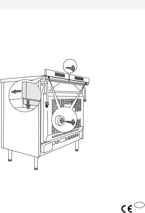
Assembling the backguard
■ Remove the two spacers “A” and the screw “B” from the rear of the cooktop.
■ |
Assemble the backguard |
|
as shown in figure 1 and |
A |
fix it by screwing the cen- |
|
tral screw “B” and the |
|
spacers “A”. |
Fig. 1
Declaration of CE conformity
This cooker has been designed, constructed and marketed in compliance with:
-Safety requirements of EU Directive "Gas" 90/396/EEC;
-Safety requirements of EU Directive "Low Voltage" 2006/95/EC;
-Protection requirements of EU Directive "EMC" 2004/108/EC; GB
- Requirements of EU Directive 93/68/EEC.
4

Features and technical data
Gas burners |
|
Note: |
||
1. |
Auxiliary burner (A) |
1,00 kW |
The electric ignition is incorporated in |
|
the knobs. |
||||
2. |
Semi-rapid burner (SR) |
1,75 kW |
||
The appliance has a safety valve system |
||||
3. |
Rapid burner (R) |
3,00 kW |
||
4. |
Triple-ring burner (TR) |
3,50 kW |
fitted, the flow of gas will be stopped if |
|
|
|
|
and when the flame should accidentally |
|
|
|
|
go out. |
|
1
2
3
4 |
1 |
2
Fig. 2
5
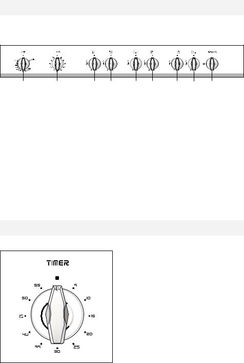
Control panel
Fig. 3
1 |
2 |
3 |
4 |
5 |
6 |
7 |
8 |
9 |
CONTROL PANEL - Controls description
1.Gas oven / gas grill control knob
2.Minute counter
3.Front left burner control knob
4.Rear left burner control knob
5.Front central burner control knob
6.Rear central burner control knob
7.Rear right burner control knob
8.Front right burner control knob
9.Oven light/rotisserie control knob
Minute counter
Minute counter
The minute counter is a timed acoustic warning device which can be set for a maximum of 60 minutes.
The knob (Fig. 4) must be rotated clockwise as far as the 60 minute position and then set to the required time by rotating it anticlockwise.
Fig. 4
6
How to use the hob burners
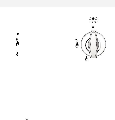
Hob burners
Each hob burner is controlled by a separate gas tap operated by a control knob (fig. 5) which has 3 positions marked on the control panel, these are:
– Symbol |
: tap closed (burner off) |
– Symbol |
: High (maximum) |
– Symbol |
: Low (minimum) |
Push in and turn the knob anti-clockwise to the
Fig. 5
selected position.
The maximum aperture position permits rapid boiling of liquids, whereas the minimum aperture position allows slower warming of food or maintaining boiling conditions of liquids.
To reduce the gas flow to minimum, rotate the knob further anti-clockwise to point the indicator towards the small flame symbol.
Other intermediate operating adjustments can be achieved by positioning the indicator between the maximum and minimum aperture positions, not between the maximum aperture and closed positions.
N.B. When the hob is not being used, set the gas knobs to their closed positions and also close the cock valve on the gas bottle or the main gas supply line.
Lighting of the hob burners
To ignite the burner, the following instructions are to be followed:
1 – Press in the corresponding knob and turn counter-clockwise to the full flame position marked by the  symbol (fig. 5) and hold the knob in until the flame has been lit.
In the case of a mains failure light the burner with a match or lighted taper.
2 – Wait about ten seconds after the gas lighting before releasing the knob (starting time for the valve).
3 – Adjust the gas valve to the desired power.
Important
If the burner flame should go out for some reason, the safety valve will automatically stop the gas flow.
To re-light the burner, return the knob to the closed  position, wait for at least 1 minute and then repeat the lighting procedure.
If your local gas supply makes it difficult to light the burner with the knob set to maximum, set the knob to minimum and repeat the operation.
7
Choice of burner
The burner must be chosen according to the diameter of the pans and energy required.
Burners |
Pan diameter |
|
|
|
Auxiliary |
12 ÷ 14 cm |
|
|
|
|
|
|
|
|
Semi-rapid |
16 ÷ 24 cm |
|
|
|
|
|
|
|
|
Rapid |
24 ÷ 26 cm |
|
|
|
Triple-ring |
26 ÷ 28 cm |
|
|
|
|
|
|
|
|
Wok |
max 36 cm |
|
Fig. 6 |
|
|
|
|
||
do not use pans with concave or convex bases |
||||
|
|
|||
Saucepans with handles that are excessively heavy in relation to the weight of the pan are less safe as they are more likely to tip.
Pans which are positioned centrally on burners are more stable than those which are offset.
It is far safer to position the pan handles in such a way that they cannot be accidentally knocked.
When deep fat frying fill the pan only one third full of oil.
DO NOT cover the pan with a lid and DO NOT leave the pan unattended.
In the unfortunate event of a fire, leave the pan where it is and turn off all controls. Place a damp cloth or correct fitting lid over the pan to smother the flames.
DO NOT use water on the fire.
Leave the pan to cool for at least 30 minutes.
8
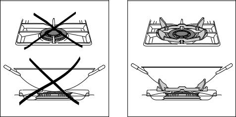
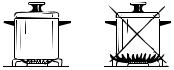
Correct use of triple-ring burner
The flat-bottomed pans are to be placed directly onto the pan-support.
To use the WOK you need to place the proper stand in order to avoid any faulty operation of the triple-ring burner (Fig. 7 - 8).
IMPORTANT:
The special grille for wok pans (fig. 8) MUST BE PLACED ONLY over the pan-rest for the triple-ring burner.
WRONG |
Fig. 7 |
CORRECT |
Fig. 8 |
9
How to use the gas oven
Lighting the oven gas burner
The thermostat allows the automatic control of the temperature.
The gas delivery to the oven burner is controlled by a two way thermostatic tap (oven and grill burners) with flame-failure device.
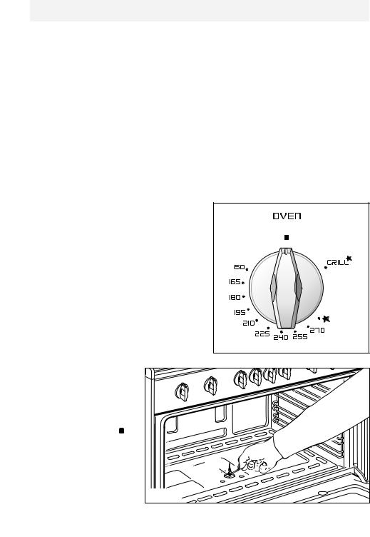
To light the oven burner operate as follow:
1)Open the oven door.
2)Lightly press and turn the thermostat knob anti-clockwise to max position “ 
 ”.
”.
3)Press the knob right down to prime the electric ignition.
WARNING: Risk of explosion! The oven door must be open during this operation.
In case of power cut, press the knob and immediately approach a lighted match to the opening “A” (fig. 9). Never continue this operation for more than 15 seconds. If the burner has still not ignited, wait for about 1 minute prior to repeating the ignition.
4)Wait about 10/15 seconds after the burner
lighting before releasing the knob (time of priming of the valve).
5) Close the oven door slowly and adjust the burner according to the power required.
Should the flame of the burner estinguish for any reason, the safety valve will cut off automatically the gas flow to the tap.
To re-start operation, take the knob to the “ ” OFF position, wait for at least 1 minute and repeat operations as above explained.
Oven |
Fig. 10 |
|
|
thermostat |
|
The oven thermostat (fig. |
|
10) is marked with num- |
|
bers, these correspond to |
|
the oven temperature, in |
|
addition the “OFF” position |
|
is shown by the symbol . |
|
To choose the required oven |
|
temperature, turn the con- |
|
trol knob until its line mark is |
A |
level with the temperature |
|
required on the control |
|
panel (facia). |
Fig. 9 |
10
Oven cooking temperatures
MARK |
APPROX. |
HEAT OF |
TYPE OF DISH TO COOK |
||
TEMP. |
OVEN |
|
|||
|
|
|
|
||
|
|
|
|
|
|
150 |
|
150°C |
Very cool |
Meringue cakes, |
|
|
|
|
|
oven |
slow cooking items |
|
|
|
|
|
|
|
• |
165°C |
Cool or |
Milk puddings, very rich fruit |
|
|
|
|
|
slow oven |
cakes, i.e., Christmas |
|
|
|
|
|
|
180 |
|
180°C |
Cool or |
Stews, casseroles, braising, |
|
|
|
|
|
slow oven |
rich fruit cakes, i.e., Dundee |
|
|
|
|
|
|
|
• |
195°C |
Warm oven |
Biscuits, rich plain cakes |
|
|
|
|
|
|
i.e., Madeira. Low temp. roasting |
|
|
|
|
|
|
210 |
|
210°C |
Moderate |
Plain cakes, Victoria |
|
|
|
|
|
oven |
sandwich, raised meat pies |
|
|
|
|
|
|
|
• |
225°C |
Fairly hot |
Small cakes, savoury flans, |
|
|
|
|
|
oven |
fish |
|
|
|
|
|
|
240 |
|
240°C |
Hot oven |
Plain cakes and buns, swiss rolls, |
|
|
|
|
|
|
fruit pies. High temp. roasting |
|
|
|
|
|
|
|
• |
245°C |
Moderately |
Bread and bread rolls etc., scones, |
|
|
|
|
|
hot oven |
flaky and rough puff pastry, |
|
|
|
|
|
yorkshire pudding |
|
|
|
|
|
|
270 |
|
270 |
Very hot |
Sausage rolls, mince pies, puff |
|
• |
|
|
285 |
oven |
pastry, pizza |
|
|
|
|
|
Browning ready cooked dishes |
|
|
|
|
|
|
|
|
|
|
|
|
11
How to use the gas grill
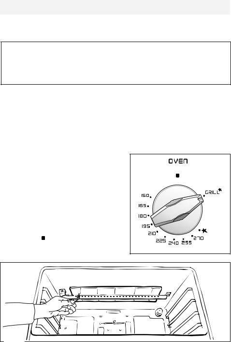
Lighting the grill gas burner
Do not grill with oven door closed.
Always fit the heat shield supplied with the cooker under the front panel before commencing operations (Fig. 13).
WARNING. The heat shield and the oven door reaches a very high temperature whilst in use. Keep children away and allow to cool before removing.
The grill burner generates the infra-red rays for grilling.
To light the grill burner operate as follow:
1)Open the oven door.
2)Lightly press and turn the thermostat knob clockwise to the 

 position (fig. 12).
3)Press the knob right down to prime the electric ignition.
WARNING: Risk of explosion! The oven door must be open during this operation.
In case of power cut, press the knob and put a lighted match to the right and left side of the burner (fig. 11).
Never continue this operation for more than 15 seconds. If the burner has still not ignited, wait for about 1 minute prior to repeating the ignition.
4) Wait about 10/15 seconds after the burner lighting before releasing the knob (time of priming of the valve).
5) Half-close the oven door slowly.
Should the flame of the burner estin- |
|
|
guish for any reason, the safety valve |
|
|
will cut off automatically the gas flow to |
|
|
the tap. To re-start operation, take the |
|
|
knob to the “ ” OFF position, wait for |
|
|
at least 1 minute and repeat operations |
Fig. 12 |
|
as above explained. |
||
|
Fig. 11
12
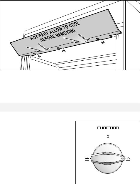
Notes:
– The grill burner has only one setting, that is full-on
– It is important that the heat shield is fitted the correct way up, as shown in the figure 13.
Fig. 13
IMPORTANT WARNING
For best results when using the grill, place the shelf on the second level and when using the grill pan handle avoid contact with the heat shield which will be
HOT during use
Oven light
The cooker is equipped with a light that illuminates the oven to enable visually controlling the food that is cooking.
This light is controlled by a switch knob (fig. 14).
Fig. 14
13
Rotisserie
This is used for spit roasting under the grill and comprises:
–an electric motor fitted to the rear of the oven
–a stainless steel skewer provided with slide-out heatless handgrip and two sets of adjustable forks
–a skewer support to be fitted in the
middle runner.
The rotisserie motor is operated by a switch knob (Fig. 15).
Fig. 15
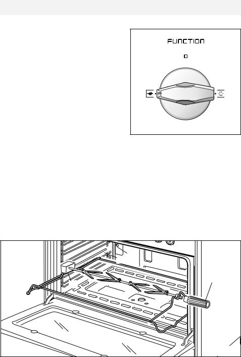
Use of the rotisserie
–Insert the tray into the lowest rack holders of the oven and insert the rod support into the intermediate rack holders.
–Put the meat to be cooked onto the rod, being careful to secure it in the center with the special forks.
–Insert the rod into the side gear opening “P”
–Remove the grip “H” by turning it to the left.
–Insert completely the rotisserie support; the shaft “S” must be inserted in the spit motor collar “G”.
The rotation direction of the rotisserie can be either clokwise or counter-clockwise.
S G
H
P
Fig. 16
14
 Loading...