

CCTV Camera Pros iDVR-RT16 User Manual
iDVR-RT16
Real Time Stand Alone Surveillance DVR
User Manual
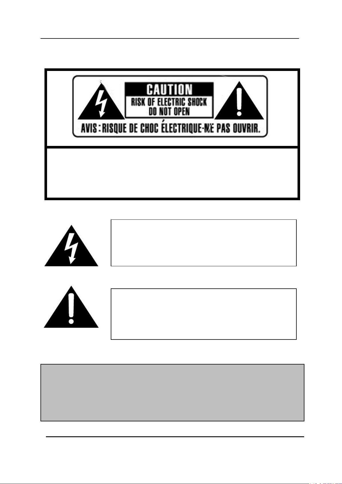
The lightning flash with arrowhead symbol, within an equilateral
triangle, is intended to alert the user to the presence of un insulated
“dangerous voltage” within the product‟s enclosure that may be of
sufficient magnitude to constitute a risk of electric shock to persons.
The exclamation point within an equilateral triangle is intended to
alert the user to the presence of important operating and
maintenance (servicing) instructions in the literature accompanying
the appliance.
WARNING:
TO PREVENT FIRE OR ELECTRIC SHOCK HAZARD,
DO NOT EXPOSE THIS APPLIANCE TO RAIN OR MOISTURE.
SAFETY PRECAUTIONS
CAUTION:
TO REDUCE THE RISK OF ELECTRIC SHOCK, DO NOT REMOVE COVER (OR BACK).
NO USER SERVICEABLE PARTS INSIDE. REFER SERVICING TO QUALIFIED
SERVICE PERSONNEL.
1 DIGITAL VIDEO RECORDER

Contents
Disclaimer .............................................................................................. 5
Warning .................................................................................................. 5
Caution .................................................................................................. 6
Preventing Malfunction......................................................................... 7
Regulatory ............................................................................................. 7
Package Contents ................................................................................. 8
I.CONTROLS .......................................................................................... 9
1. Front Panel ...................................................................................................... 9
2. Rear Panel Connectors ................................................................................. 11
3. Remote Controller ........................................................................................ 13
4. Virtual Keypad for Mouse Control ............................................................... 14
II. INSTALLATION & CONNECTIONS .................................................. 15
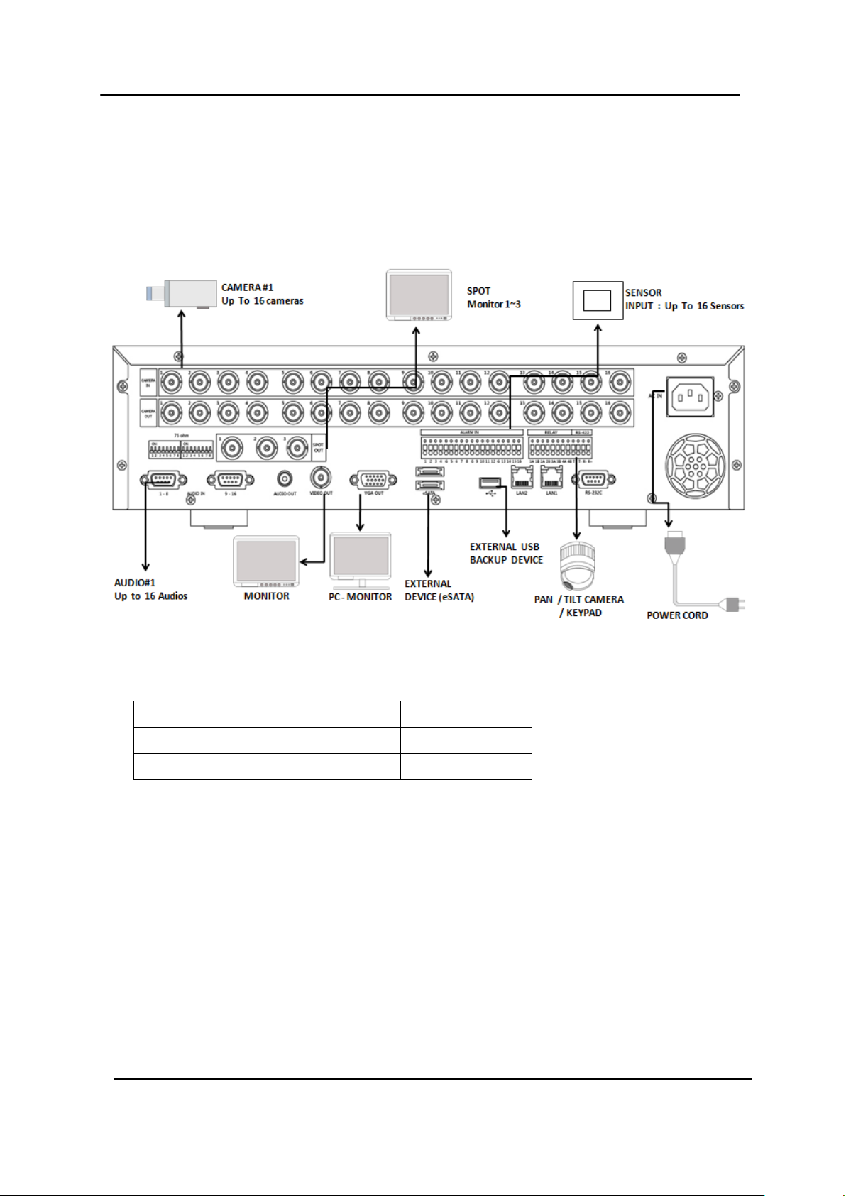
1. Camera, Monitor, Audio, Alarm sensor and Power cord ........................... 15
2. Alarm inputs and Alarm outs ................................................................ ....... 16
2.1. Connection of N.O (Normally Open) ............................................................................ 16
2.2. Connection of N.C (Normally Close) ............................................................................ 17
3. PTZ and controller connection .................................................................... 18
3.1. Connecting the Speed Dome directly into DVR .......................................................... 18
3.2. Connecting Both Speed Dome and DVR via J-box .................................................... 18
3.3. Connecting Single User with 2 DVR Configuration .................................................... 19
III.QUICK START PAGE ....................................................................... 21
IV.LIVE VIEWING ................................................................................. 23
1. Display Overview .......................................................................................... 23
2. Multi-screen Display and Sequencing ........................................................ 25
2.1. Screen Display. ............................................................................................................... 25
2.2. Multi-screen Display and Switch Sequencing Display. .............................................. 25
3. Quick button for multi screen Display. ....................................................... 26
3.1. Quick multi split mode change ..................................................................................... 26
3.2. Repositioning ................................................................................................................. 26
4. Zooming ........................................................................................................ 27
5. Spot Monitor.................................................................................................. 28
V. OPERATION ..................................................................................... 29
1. LOG IN/OUT. .................................................................................................. 29
2. NAVIGATION THE MENU .............................................................................. 30
VI. SETUP............................................................................................. 31
2 DIGITAL VIDEO RECORDER

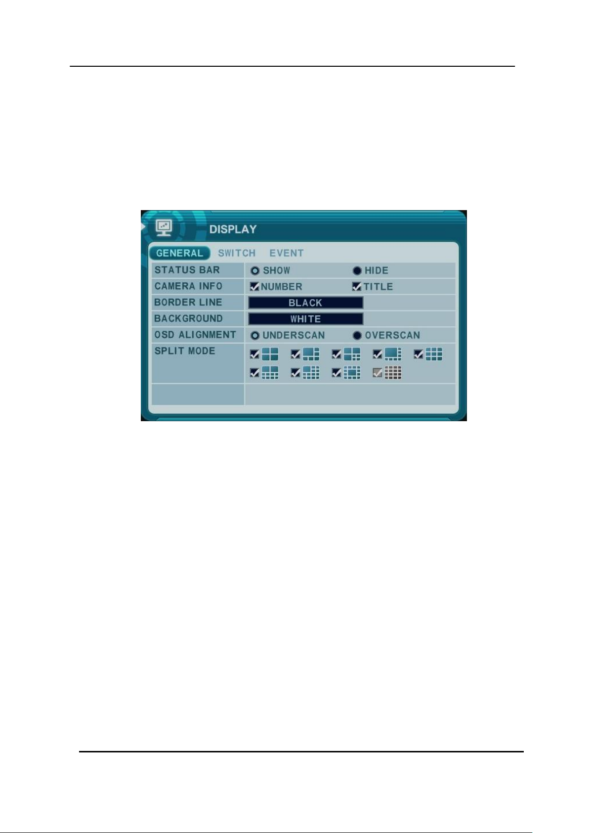
1. DISPLAY ........................................................................................................ 31
1.1. GENERAL ........................................................................................................................ 31
1.2. SWITCH Setup (Monitor Configure) ............................................................................. 32
1.3. EVENT ............................................................................................................................. 33
2. CAMERA ........................................................................................................ 34
3. RECORD ........................................................................................................ 37
3.1. Record General .............................................................................................................. 37
3.2. Continues /Normal Recording ...................................................................................... 38
3.3. Event Recording............................................................................................................. 39
3.4 Continues + Event (Motion/Alarm) Recording ............................................................. 41
4. SCHEDULE .................................................................................................... 42
4.1. CHART Setup .................................................................................................................. 42
4.2. Holiday Setup ................................................................................................................. 44
5. DISK ................................................................................................ ............... 45
5.1. DISK Manager ................................................................................................................. 45
5.2. Recording DISK .............................................................................................................. 47
5.3. SMART STATUS ............................................................................................................. 48
6. NETWORK ..................................................................................................... 49
6.1. ETHERNET ...................................................................................................................... 49
6.2. GENERAL ........................................................................................................................ 50
6.3. EMAIL .............................................................................................................................. 51
6.4. SMTP ............................................................................................................................... 52
6.5. DDNS (Dynamic DNS) .................................................................................................... 53
6.6 Router & Port Forwarding .............................................................................................. 55
7. DEVICE .......................................................................................................... 57
7.1. GENERAL ........................................................................................................................ 57
7.2. ALARM ............................................................................................................................ 58
7.3. PTZ EVENT ..................................................................................................................... 60
8. SYSTEM ......................................................................................................... 61
8.1. GENERAL ........................................................................................................................ 61
8.2. TIME ................................................................................................................................. 62
8.3. ACCOUNT ....................................................................................................................... 63
8.4. UPDATE ........................................................................................................................... 65
8.5. INFO ................................................................................................................................. 66
VII. PAN/TILT ZOOM CONTROL .......................................................... 67
1. P.T.Z .Menu .................................................................................................... 67
2. Preset & Tour ................................................................................................ 68
3 DIGITAL VIDEO RECORDER

3. Custom Functions ........................................................................................ 70
4.Auto Pan / Auto Tilt / Power .......................................................................... 70
VIII.PLAYBACK /SEARCH ................................................................... 71
1. Playback ........................................................................................................ 71
2. Time Search .................................................................................................. 72
2.1 Multi Channel Playback ................................................................................................. 72
2.2 Preview Search (Single Channel Playback) ................................................................ 73
2.3 Event Record Search ..................................................................................................... 74
2.4 Event Source Search ...................................................................................................... 74
2.5 Event Area Search (Single Channel Playback) ........................................................... 75
3.Go to Search .................................................................................................. 75
4.Log List Search .............................................................................................. 76
IX.BACKUP .......................................................................................... 78
1. Manual Back up ............................................................................................ 78
1.1 Internal DVD- R/W .......................................................................................................... 78
1.2 External USB HDD/ Memory Stick ................................................................................. 80
1.3 Back up Range Setup ..................................................................................................... 80
2. Auto Back up(FTP) ....................................................................................... 81
3. Log List Back up ........................................................................................... 82
X.SPECIFICATION ............................................................................... 83
4 DIGITAL VIDEO RECORDER

Disclaimer
Warning
The information in this manual is believed to be accurate and reliable as of the date of
publication. The information contained herein is subject to change without notice. Revisions
or New editions to this publication may be issued to incorporate such change
We makes no warranties for damages resulting from corrupted or lost data due to a mistaken
operation or malfunction of the Digital Video Recorder, the software, the hard drives, personal
computers, peripheral devices, or unapproved/unsupported devices.
Do not cover the ventilation opening or slots on the outer casing. To prevent the appliance
from overheating, provide at least two inches of air space around the vent and the slots.
Do not drop metallic parts through slots. This could permanently damage the Digital Video
Recorder. Immediately turn the DVR‟s power off or unplug the power cord from the power
outlet. Contact a qualified service personnel authorized by your equipment distributor
Do not attempt to disassemble or alter any part of the equipment that is not expressly
described in this guide. Disassembly or alteration may result in high voltage electrical shock.
Qualified service personnel authorized by your equipment distributor should conduct internal
inspections, alterations and repairs.
Stop operating the equipment immediately if it emits smoke or noxious fumes. Failure to do
so may result in fire or electrical shock. Immediately turn the DVR‟s power off, remove the
power cable from the power outlet. Confirm that smoke and fume emissions have ceased.
Please consult your DVR distributor.
Stop operating the equipment if a heavy object is dropped or the casing is damaged. Do not
strike or shake. Failure to do so may result in fire or electrical shock. Immediately turn the
DVR‟s power off or unplug the power cord from the power outlet. Please consult your DVR
distributor.
Do not allow the equipment come into contact with, or become immersed in, water or other
liquids. Do not allow liquids to enter the interior. The DVR has not been waterproofed. If
Do not use substances containing alcohol, benzene, thinners or other flammable substances
the exterior comes into contact with liquids or salt air, wipe it dry with a soft, absorbent cloth.
In the event that the water or other foreign substances enter the interior, immediately turn the
DVR‟s Power off or unplug the power cord from the power outlet. Continued use of the
equipment may result in fire or electrical shock. Please consult your DVR distributor.
5 DIGITAL VIDEO RECORDER

Caution
to clean or maintain the equipment. The use of these substances may lead to fire. Use a
dry cloth on a regular periodic basis and wipe away the dust and dirt that collects on the
device. In dusty, humid or greasy environments, the dust that collects around the ventilation
or the slots on the outer casing over long periods of time may become saturated with
humidity and short-circuit, leading to fire.
Do not cut, damage, alter or place heavy items on the power cord. Any of these actions
may cause an electrical short circuit, which may lead to fire or electrical shock.
Do not handle the device or power cord if your hands are wet. Handling it with wet hands
may lead to electrical shock. When unplugging the cord, ensure that you hold the solid
portion of the plug. Pulling on the flexible portion of the cord may damage or expose the
wire and insulation, creating the potential for fires or electrical shocks.
Use only the recommended power accessories. Use of power sources not expressly
recommended for this equipment may lead to overheating, distortion of the equipment, fire,
electrical shock or other hazards.
Do not place the batteries near a heat source or expose them to direct flame or heat.
Neither should you immerse them in water. Such exposure may damage the batteries and
lead to the leakage of corrosive liquids, fire, electrical shock, explosion or serious injury.
Do not attempt to disassemble, alter or apply heat to the batteries. There is serious risk of
injury due to an explosion. Immediately flush with water any area of the body, including the
eyes and mouth, or clothing that comes into contact with the inner contents of the battery. If
the eyes or mouth contact these substances, immediately flush with water and seek medical
assistance from a medical professional.
Avoid dropping or subjecting the batteries to severe impacts that could damage the casings.
It could lead to leakage and injury.
Do not short-circuit the battery terminals with metallic objects, such as key holders. It could
lead to overheating, burns and other injuries.
The supplied power supply and power cord are designed for exclusive use with the Digital
Video Recorder. Do not use it with other products or batteries. There is a risk of fire and
other hazards.
Do not operate the appliance beyond its specified temperature, humidity or power source
ratings. Do not use the appliance in an extreme environment where there is high
temperature or high humidity. Use the device at temperatures within +0°C - +40°C (32°F 104°F) and humidity below 90 %. The normal operating power source for this device is 100V240V AC 50/60Hz.
6 DIGITAL VIDEO RECORDER

Preventing Malfunction
Regulatory
CAUTION
- Risk of Explosion if Battery is replaced by an Incorrect Type. Dispose of Used Batteries
aAccording to the Instructions.
- The socket-outlet shall be installed near the equipment and shall be easily accessible
Avoid Strong Magnetic Fields. Never place the DVR in close Proximity to electric motors or
other equipment generating strong electromagnetic fields. Exposures to strong magnetic
fields may cause malfunctions or corrupt image data.
Avoid Condensation Related Problems. Moving the equipment rapidly between hot and cold
temperatures may cause condensation (water droplets) to form on its external and internal
surfaces. You can avoid this by placing the equipment in an airtight, resalable plastic bag and
letting it adjust to temperature changes slowly before removing it from the bag.
If Condensation forms inside the Digital Video Recorder. Stop using the equipment
immediately if you detect condensation. Continued use may damage the equipment. Remove
the power cord from the power outlet and wait until the moisture evaporates completely
before resuming use.
FCC Compliance : This equipment has been tested and found to comply with the limits for a
Class A digital device, pursuant to part 15 of the FCC Rules. These limits are designed to provide
reasonable protection against harmful interference when the equipment is operated in a commercial
environment. This equipment generates, uses, and can radiate radio frequency energy and, if no
installed and used in accordance with the instruction manual, may cause harmful interference to radio
communications. Operation of this equipment in a residential area is likely to cause harmful
interference in which case the user will be required to correct the interference at his own expense.
NOTE: THE MANUFACTURER IS NOT RESPONSIBLE FOR ANY RADIO OR TV INTERFERENCE
CAUSED BY UNAUTHORIZED MODIFICATIONS TO THIS EQUIPMENT. SUCH MODIFICATIONS
COULD VOID THE USER'S AUTHORITY TO OPERATE THE EQUIPMENT.
7 DIGITAL VIDEO RECORDER

CONTENTS
QUANTITY
REMARK
DIGITAL VIDEO RECORDER
1 UNIT
CLIENT SOFTWARE CD
1
REMOTE CONTROLLER
1
Audio In Cable Connector
(1~8CH, 9~16CH)
1
8CH
2
16CH
BATTERY (AAAsize)
2
POWER CORD
1
USER GUIDE
1
Package Contents
Please check the package and contents for visible damage. If any components are damaged or
missing, do not attempt to use the unit, contact the supplier immediately. If the unit must be
returned, it must be shipped in the original packing box.
8 DIGITAL VIDEO RECORDER
I.CONTROLS
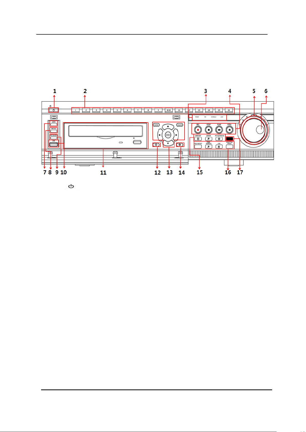
1. Front Panel
1) POWER : Press this button to turn the power on; press again to turn the power off. The
POWER LED (red) lights/goes off when the power is on/off.
2) Numeric [0~16] : These buttons have a number of functions to enter data and to make selections.
They are used to enter numerical data when prompted for the password, to make channel/camera
selection, to choose the day in schedule option, and to enter alphabets to label each channel.
3) Mode Indicator: Five LEDs display the status of the Digital Video Recorder. From the left, Power
(red), Recording (red), Scheduled Recording (green), Lock (green) and Network (green).
4) Playback / Record Control : Used to Start and Stop Recording or Playback.
5) Shuttle Ring : Used to control the playback speed, and to rewind or forward the image.
6) JOG Dial : Used to forward or reverse the image during playback (field-by-field).
7) LOCK: Press this button to lock all units‟ key buttons including the remote controller. The LOCK
LED (green) lights/goes off when the lock is on/off. To release press it again and enter the
administer password.
8) BACKUP: Press this button to begin making a backup copy of the hard drive. If there is no
peripheral recording device connected, this button cannot be used.
9 DIGITAL VIDEO RECORDER

9) EXT. Search : Press this button to start external HDD search.
10) USB : USB compliant port allows use of memory sticks to backup video files or S/W
upgrade.
11) ODD : CD/DVD - RW.
12) [-] : To Decrease settings
13) MENU, DIRECTION, ENTER, CANCEL:
* [ENTER]: Press this button to enter the sub menu.
* [CANCEL]: Press this button to exit menu without saving.
* [Direction]: In Menu setup mode, used to move the cursor.
In Zoom mode, used to move the zoom are.
* [MENU] : Press this button to display the MAIN MENU. Press this button to exit with saving
changes.
14) [+] : To Increase settings
15) Screen Control Buttons
DISPLAY: Press this button to display the cameras in multi-screen mode or to switch
sequence function.
[ZOOM]: Press this button to display zoom area box; press [ENTER]
to enlarge the image. Pressing cursors can move this zoom area.
[P/T/Z/FOCUS]: Press this button to control a PAN/TILT/ZOOM camera
via RS-485 connection.
16) Function Buttons
LOG IN/OUT : Toggles log in and out.
TIME SEARCH: Press this button to display the Time Search menu.
LOG : Press this button to display the LOG-list screen.
[SHUTTLE HOLD]: This button retains the selected playback or reverses playback speed. It
is also used for controlling Spot out while it‟s Live viewing.
17) Remote control signal receiver : Do not block the receiver as the remote controller needs the
line of sight to the receiver.
10 DIGITAL VIDEO RECORDER
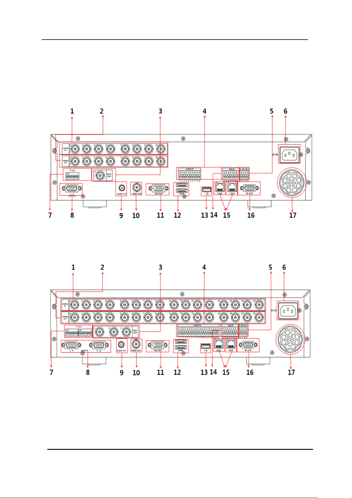
2. Rear Panel Connectors
8-Channel
16-Channel
11 DIGITAL VIDEO RECORDER

1) Camera Inputs : BNC input connectors ( 8 / 16CH)
2) Camera Outputs : LOOP-OUT connectors ( 8 / 16CH : BNC,)
3) Spot out connector : 8ch – 1 / 16ch – 3 SPOT OUT(Digital)
4) ALARM IN : 8/16 alarm/sensor inputs
5) RS-422 : For connecting to PTZ camera.
6) AC power socket : Universal voltage
7) 75 Ohm Termination (1~8/ 1~16)
8) AUDIO Input connectors : D-SUB to RCA ( 8CH : 1~8CH , 16CH : 1~8CH,9~16CH )
9) AUDIO Output (1) connectors: RCA
10) Composite Monitor Output : BNC standard composite video output connector.
11) VGA out connector.
12) eSATA connector: For connecting e-SATA compatible devices.
13) USB 2.0 connector: For connecting USB compatible devices.
14) ALARM OUT : 1~4
15) RJ-45 Ethernet Port (2): For connecting to remote PC via Ethernet network.
10/100/1000 BASE-T
16) RS-232C [D-SUB 9PIN] : For connecting to Debugging.
17) Power Fan
12 DIGITAL VIDEO RECORDER

STOP
PLAY
BACK UP
DVR ID
MENU
LOG
FAST FORWARD
DISPLAY MODE
SCHEDULE /LONIN
ENTER
INFORMATION
EXT. SEARCH
REWIND
NUMBERS & ALPHABET
TIME SEARCH
ZOOM
STEP
RECORD
- BUTTON
+ BUTTON
PAN/TILT/ZOOM
3. Remote Controller
DVR ID: Set the proper DVR System ID through which to operate. Press the ID button, and
then press the number button within two seconds to select the system ID of the DVR. If you
set the System ID to Zero, you can control multiple DVRs at the same time.
13 DIGITAL VIDEO RECORDER

4. Virtual Keypad for Mouse Control
This DVR provides a virtual on-screen keyboard to perform the control by mouse.
Connect a mouse via USB port before use. If you click right button of your mouse in Live
mode and Playback mode, you will see following virtual controller. This Virtual Keyboards
operate similarly, but display different fields depending on the task being performed.
<Virtual Control Panel> <Virtual Keyboard>
14 DIGITAL VIDEO RECORDER
Audio
Input
Output
impedance (0 dB)
10 k Ohm
300 ohm
voltage range
1 Vpp
1.4 Vpp
II. INSTALLATION & CONNECTIONS
1. Camera, Monitor, Audio, Alarm sensor and Power cord
Audio
15 DIGITAL VIDEO RECORDER
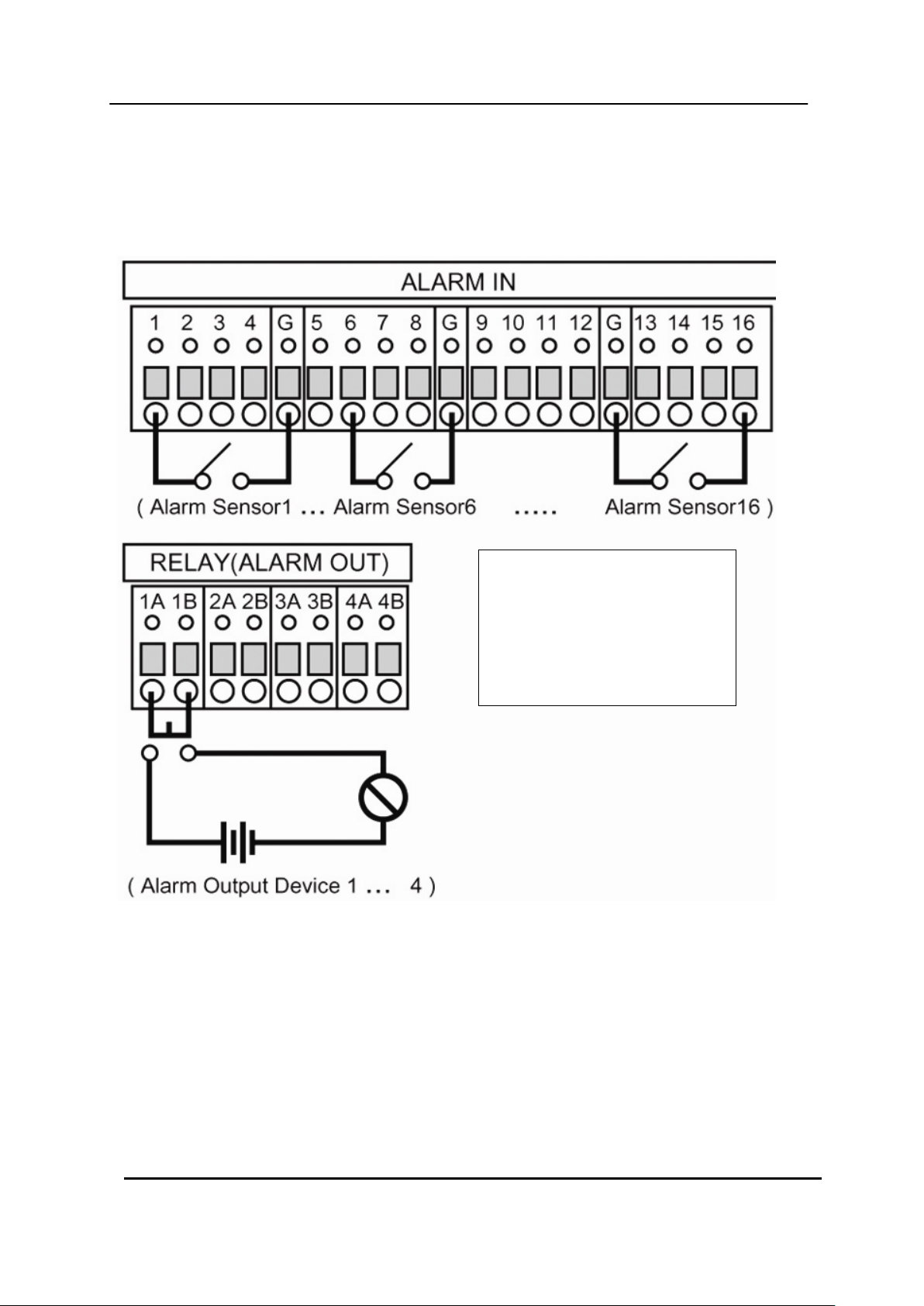
* Alarm Input( AI)
8ch: 1~8
16ch : 1~16
* G : GND
2. Alarm inputs and Alarm outs
2.1. Connection of N.O (Normally Open)
The maximum of Alarm output is 1A 30VDC, 0.5A 125V AC.
16 DIGITAL VIDEO RECORDER
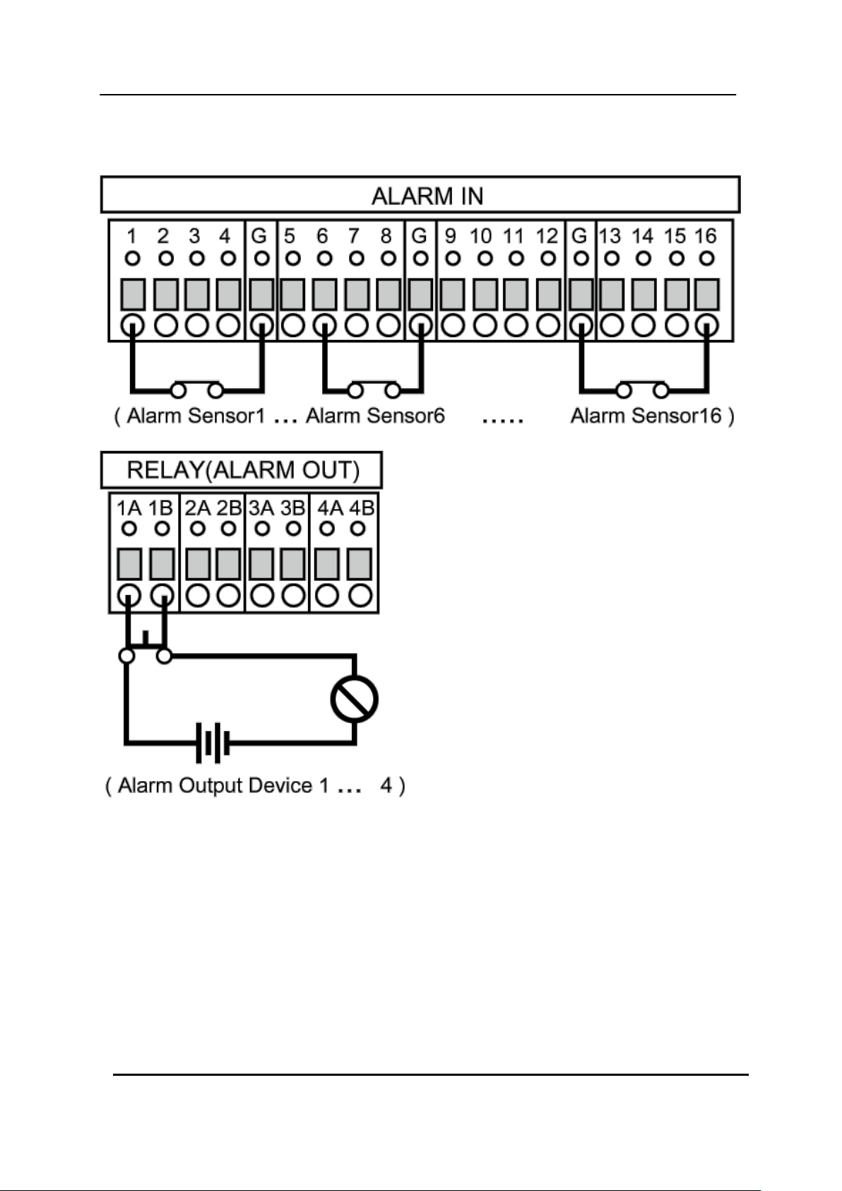
2.2. Connection of N.C (Normally Close)
17 DIGITAL VIDEO RECORDER
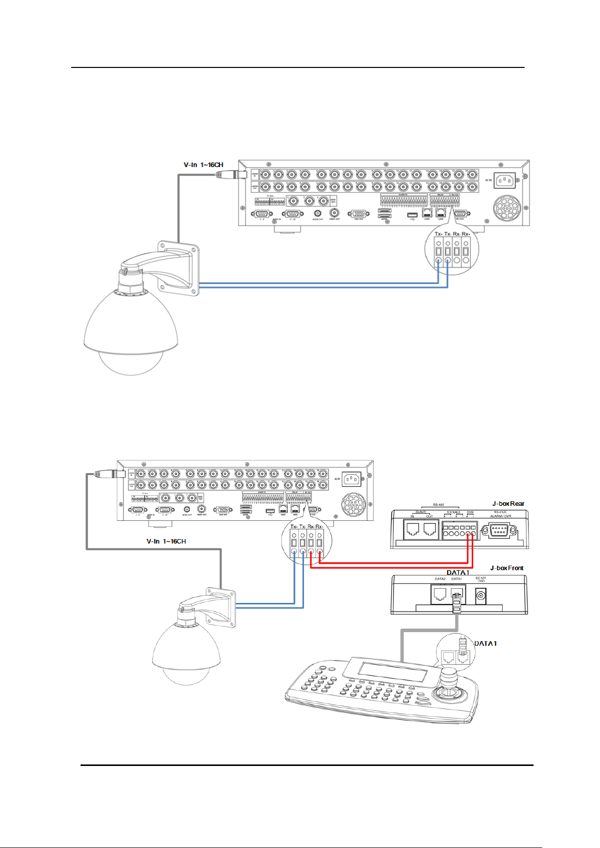
3. PTZ and controller connection
3.1. Connecting the Speed Dome directly into DVR
3.2. Connecting Both Speed Dome and DVR via J-box
18 DIGITAL VIDEO RECORDER
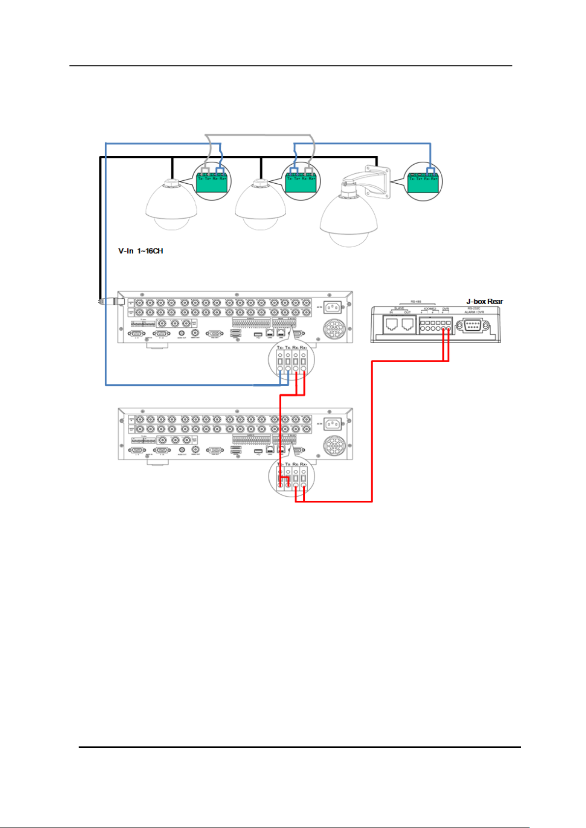
3.3. Connecting Single User with 2 DVR Configuration
Multiple PTZ cameras are connected by daisy-chaining the camera connection.
Multiple Keyboards are connected by cascade connection.
19 DIGITAL VIDEO RECORDER

<Disclaimer>
The connection and remote viewing of the DVR may not be successful
on all PC’s due to the variety of PC’s internet connection settings.
Please contact the technical support for further assistance.
4. PC system requirement for Network connection.
(a) Pentium-4 2.0GHz or Higher
(b) 512MB RAM
(c) Windows 2000, ME, Windows XP, Window Vista
<NOTE> For VISTA user.
When multiple people share a computer, user account has limited function for
Downloading. Please use the proper version depends on computer account.
(d) 16MB Video Card
(e) 10/100/1000-BaseT Ethernet Port
(f) CAT-5/6 UTP Cable for LAN
(Crossover cable for direct connect to PC)
20 DIGITAL VIDEO RECORDER
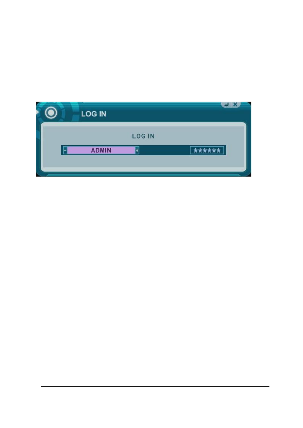
III.QUICK START PAGE
ADMIN and the default password is “000000”
The Default User ID “admin” and password to run the EMS Client software is “0”
21 DIGITAL VIDEO RECORDER
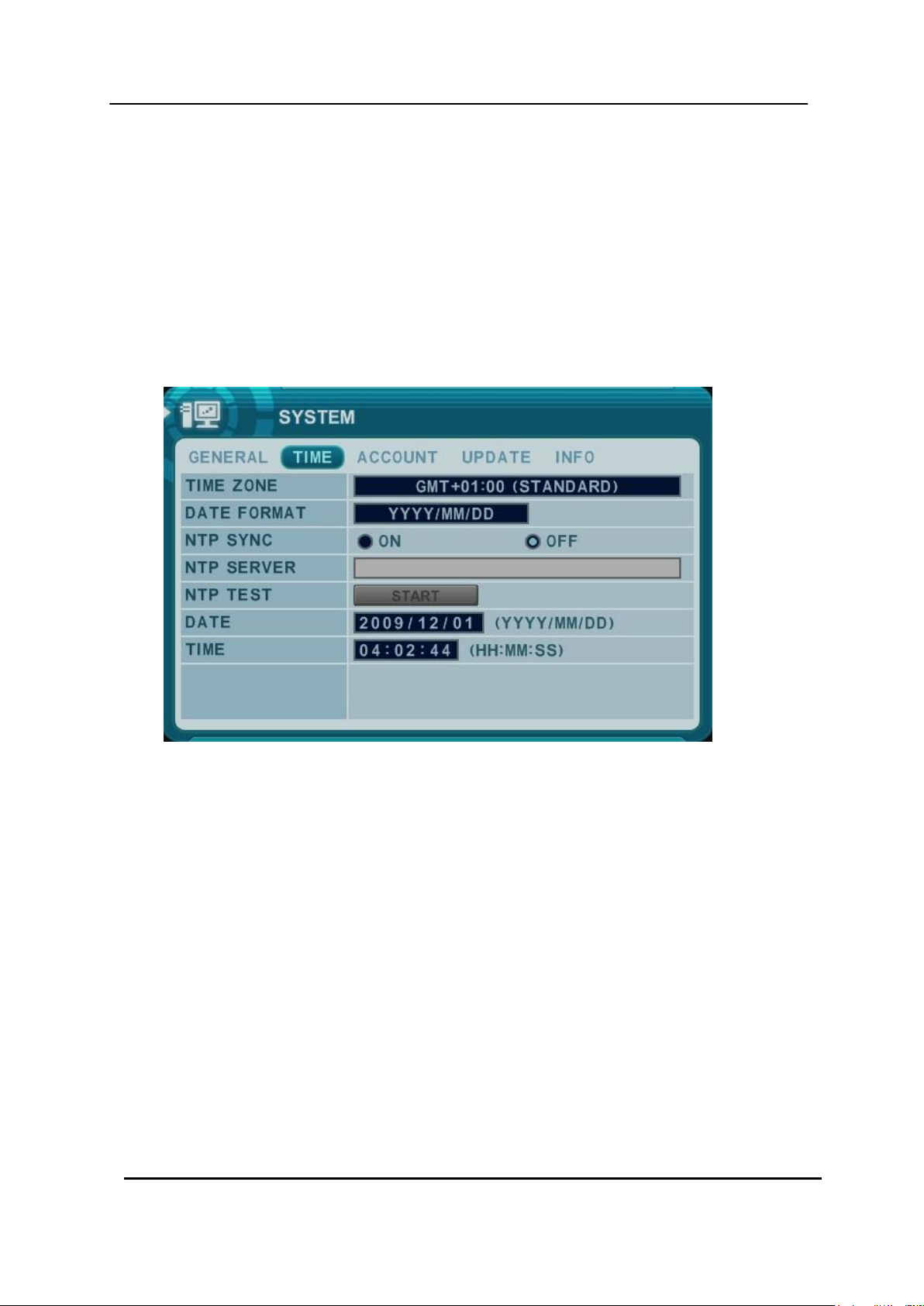
Time & Date Setting
When the DVR is powered on for the very first time, the time and date are set as default to
January 1, 2009 Thursday 01:00:00. Before any other operation of the Digital Video
Recorder, it is important to setup the time and the date. Please refer to page 63 for setting
the time and the date on the DVR.
22 DIGITAL VIDEO RECORDER
(1) (2) (3)
Camera No and Title
①
②
③
②
Camera No and Title
④
IV.LIVE VIEWING
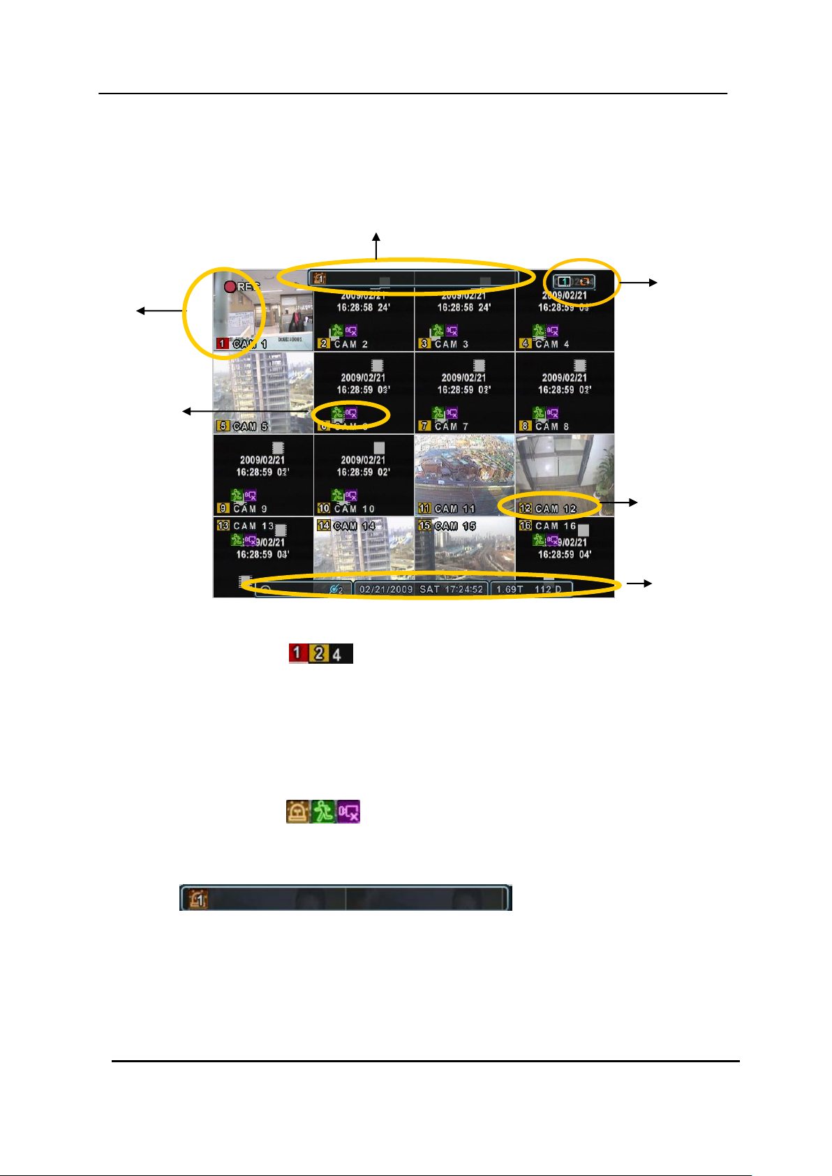
1. Display Overview
1. Recording Mode
Background color of Number will be different based on the recording status.
1) Red - Event (Motion/Alarm) Recording
2) Yellow - Continues Recording
3) Black - No Recording.
2. Event Indicator
(1) Indicate Alarm In terminal is triggered by an alarm sensor.
To appear Alarm window, press [UP] button. This button toggles between Shows
or Hide the Alarm Window.
(2) Indicate Motion detected. To disappear, press [CANCEL] button.
(3) Indicate Video Loss during Recording. To disappear, press [CANCEL] button.
23 DIGITAL VIDEO RECORDER

3. Status Bar
(1) Indicate Built-in CD/DVD R/W is connected. It‟s changed to blue color while it‟s
doing backup.
(2) Indicate an USB Device is connected on Front panel. It‟s changed to blue
color while it‟s doing backup.
(3) Indicate an USB Device is connected on Rear panel. It‟s changed to blue color
while it‟s doing backup.
(4) Indicate Login( ) or Locking status
(5) Indicate Audio Data is stored the selected time during playback and turn to blue
color.
(6) It shows Number of Client, which is connected to Network.(MAX:10)
(7) : Displays Month, Year, Time and Date.
(8) : Show you the remaining recording time of the DVR. If remaining
HDD capacity is less than 5GB, this blue “Recycling” icon will be shown up.
4. Spot Monitor indicate
: Show you Selected Spot Number and status
24 DIGITAL VIDEO RECORDER
2. Multi-screen Display and Sequencing
2.1. Screen Display.
Select any camera for Full screen display by pressing the Number button of the
desired camera.
2.2. Multi-screen Display and Switch Sequencing Display.
1) Press [DISPLAY] buttons to activate the multiscreen display. It is changed the
order as shown below among your choice of SPLIT MODE.
2) To start Auto Sequence, press [DISPLAY] buttons for 2 seconds to begin full
screen sequencing.
3) The sequence mode and dwell times are programmable. For detailed information
about configuring those, see “Switch Setup”. If the sequence mode is not
activated, it moves to Quad mode instead of Sequencing.
25 DIGITAL VIDEO RECORDER
4
8
3
7
2
6
10
1
5
9
11 12
13 14 15 16
2
3
4
8765
1
<Note> 6,4,8,10,13 split mode must be checked on <Spit mode> to use this function.
<Note> How to control on KEYPAD
1. Muliti Screen (F1 function) = 16+ Display , 4+ Display button, and so on..
2. Repositioning (F2 function) = 99+ Display button
3. Auto Sequence Start = Shift & Display(at the same time)
3. Quick button for multi screen Display.
3.1. Quick multi split mode change
- Press F1 button on the remote controller + <Number>
For example, press F1 button then number 8.
The eight channel view mode will be displayed.
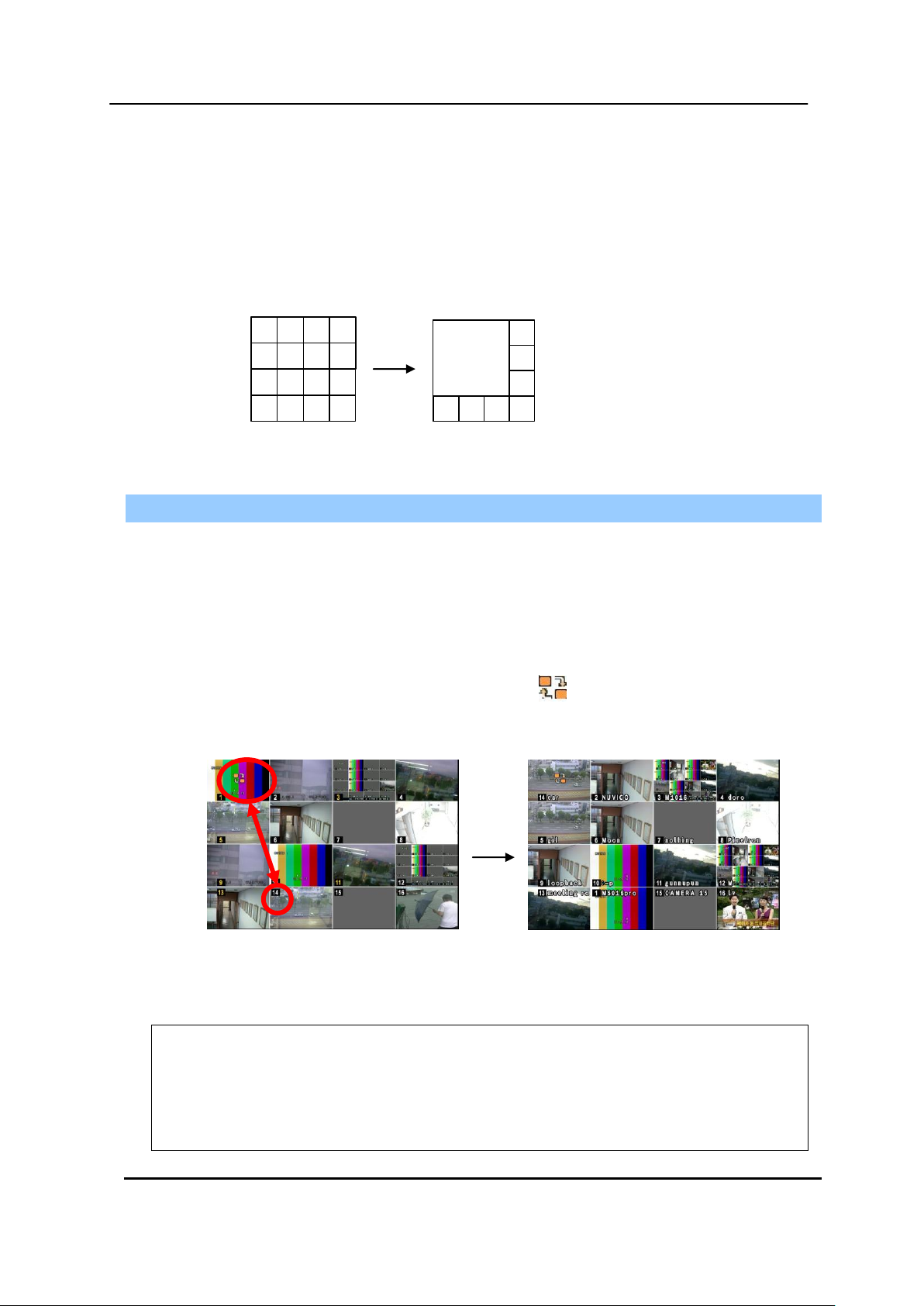
3.2. Repositioning
It is possible to reposition the camera from the bigger window with the one from a
smaller one. It is used on 6,7,8,9,10, 13,16 split mode
① Press F2 button on the remote controller. Mark will be displayed.
② Press Numeric button you wish to switching display.
③ Press [MENU] button to exit here with saving changes.
Press [Cancel] to exit without change.
Press [DISPLAY] button to rearrange.
26 DIGITAL VIDEO RECORDER
 Loading...