

Page 1
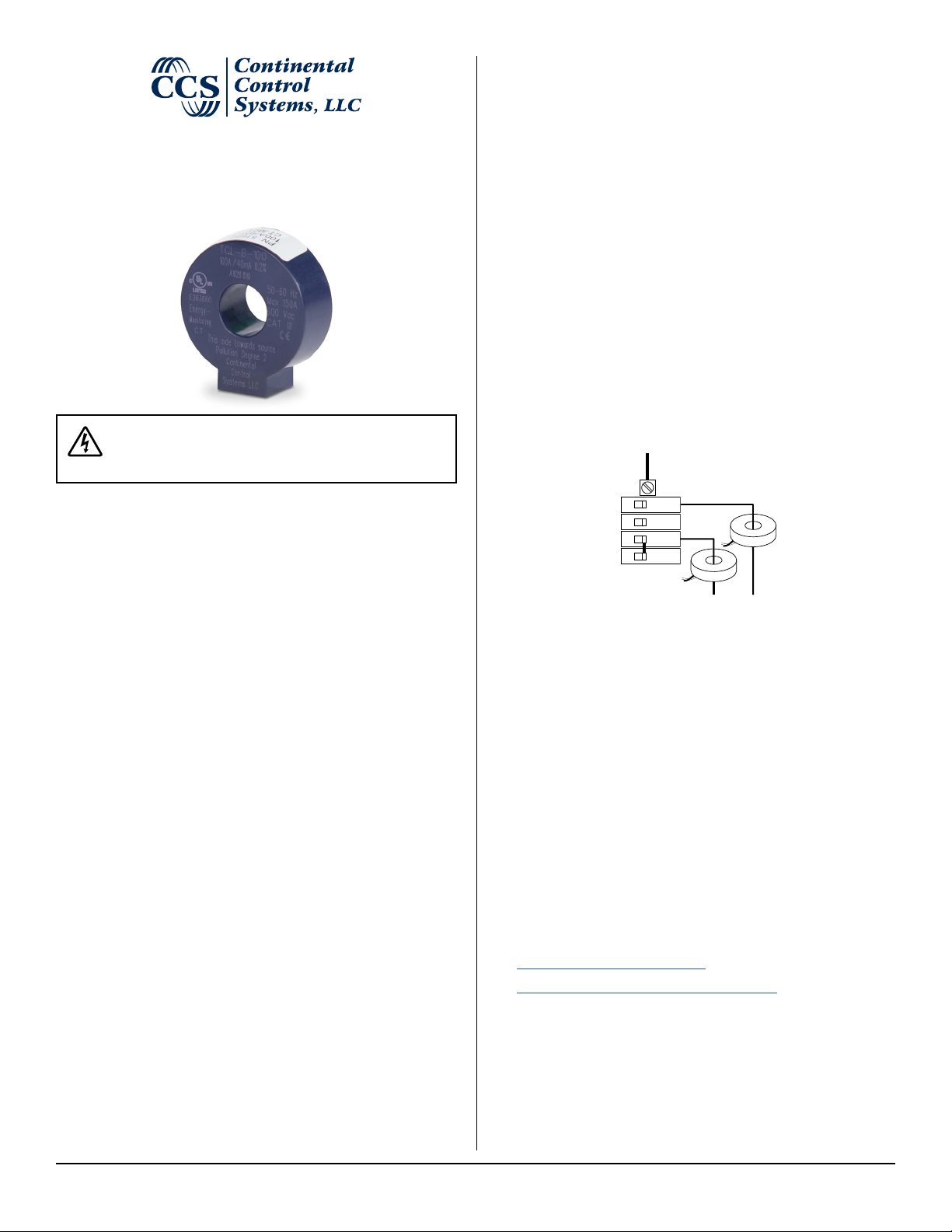
TCL-B Series
Solid-Core Current Transformer
Installation Guide
Danger: Hazardous Voltages
Potential shock hazard from dangerous high voltage
exists.
Pre-Installation Checklist
● The CT’s rated current should normally be greater than or equal to
the maximum current of the measured circuit. Ensure that the fuse or
circuit breaker’s rating does not exceed the CT’s maximum continuous
current rating.
● It is preferable to install the CT and meter or monitoring device close
to each other. However, you may extend the CT wires by 300 feet (100
m) or more by using shielded twisted-pair cable and by running the CT
wires away from high current and line voltage conductors.
Connecting the Current Transformer
1) WARNING: To reduce the risk of electric shock, always open
or disconnect the circuit from the power-distribution system
(or service) of the building before installing or servicing current
transformers.
2) Disconnect the conductor to be monitored, so that the CT may be
installed on the conductor.
3) Install the CT on the conductor with the labeled side of the CT (with
“This side towards source”) facing toward the current source: the utility
meter or the circuit breaker for branch circuits.
Note: If the CT is mounted backwards, the measured power will be
negative.
L2
The TCL-B series current transformers measure AC line current in circuits
up to 600 Vac and nominal currents up to 100 amps. They are solid-core
(toroidal) which offers high accuracy (0.3%), security, and low-cost.
They are UL Listed for eld installation within distribution and control
equipment such as panelboards, switchboards, industrial control equipment, and energy-monitoring/management equipment. They are used to
measure current on the service entrance or branch circuit conductors.
The TCL-B series CT are available with either milliamp or millivolt outputs.
They are used with electric energy meters, like the WattNode meters, or for
other current monitoring purposes.
Precautions
● Only qualied personnel or licensed electricians should install the
current transformer (CT). The line voltages of 120Vac to 600Vac can
be lethal!
● Install in accordance with ANSI/NFPA 70, “National Electrical Code”
(NEC). Follow all local electrical codes.
● Electrical codes prohibit installation of CTs in equipment where they
exceed 75% of the wiring space of any cross-sectional area.
● Do not install CTs where they block ventilation openings.
● Do not install CTs in the area of breaker arc venting.
● The CT lead wires are considered Class 1 wiring (as dened by the
NEC) and must be installed accordingly. They are not suitable for Class
2 wiring methods and should not be connected to Class 2 equipment.
● Verify that the line currents will not exceed the “Maximum Amps” (see
the Models table below) under normal operation.
● Do not install the CT where it may be exposed to temperatures below
-40°C or above 85°C (-40°F to 185°F), excessive moisture, dust, salt
spray, or other contamination.
● The current transformer cannot measure direct current (DC), and DC
will degrade the AC accuracy.
● If the equipment is used in a manner not specied by the manufac-
turer, the protection provided by the equipment may be impaired.
L1
L2
L1
L2
Breaker Panel
4) Reconnect the conductor to be monitored.
5) Optional: Secure the CT to the conductor with a cable tie.
6) Route the twisted black and white wires from the CT to the meter or
monitoring device. Be sure to secure the CTs and route the lead
wires so that they do not directly contact live terminals or busses.
7) Connect the white and black wires to the terminals on the meter or
monitoring device.
Note: If the white and black wires are reversed, the measured power
will be negative.
Note: On a WattNode meter, the white wire should be aligned with the
white dot on the label, and the black wire should be aligned with the
black dot on the label.
Note: Be careful to match the CT to the voltage phases being measured. Use colored labels or tape to identify the wires.
Source
Source
References
For more information about the TCL-B current transformer and CTs in
general, see:
● https://ctlsys.com/product/tcl-b-ct/
● https://ctlsys.com/category/current_transformer/
For more information about connecting current transformers to WattNode
meters, see the appropriate WattNode meter manual.
TCL-B Series Manual Continental Control Systems, LLC 1
Page 2
Specications
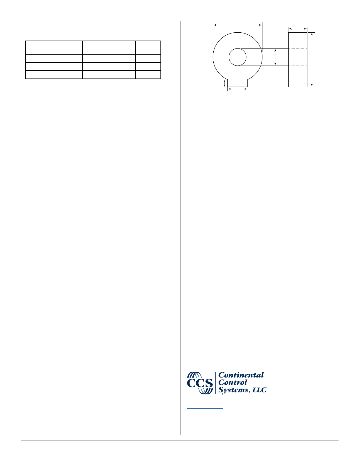
0.55 (14.0)
Models
1.46 (37.0)
0.51 (13.0)
Model Rated
TCL-B-100 100 A 0.33333 Vac 0.3%
TCL-B-050 50 A 0.33333 Vac 0.3%
TCL-B-100/40mA 100 A 40 mA 0.2%
Electrical
Line Frequency: 50 to 60 Hz
Maximum Continuous Primary Current: 250 amps
Maximum Voltage: 600 Vac
Overvoltage and Measurement Categories: CAT III: 600 Vac
Lead Wire: 2.4 m (8 feet), 18 AWG, 105°C, 600 V, twisted pair
Milliamp Ouput: Current output
Output Current: 40 mA at 100 A primary current
Output Protection: includes internal clamp Zener at 13 Vac
Millivolt Output: Voltage output, integral burden resistor
Output Voltage at Rated Amps: 0.33333 Vac (one-third volt)
Output Protection: internal burden resistor
Accuracy
Millivolt Output Accuracy (% of reading): TCL-B-xxx
Accuracy: ±0.3% from 1% to 120% of rated current
Phase angle:
±0.15 degrees (9 minutes) from 20% to 120% of rated current
±0.33 degrees (20 minutes) from 1% to 20% of rated current
IEEE C57.13 accuracy: class 0.6
IEC 60044-1 accuracy: class 0.5S
Milliamp Output Accuracy (% of reading): TCL-B-100/40mA
Accuracy: ±0.2% from 1% to 120% of rated current
Phase angle:
±0.15 degrees (9 minutes) from 20% to 120% of rated current
±0.33 degrees (20 minutes) from 1% to 20% of rated current
IEEE C57.13 accuracy: class 0.6
IEC 60044-1 accuracy: class 0.2
Regulatory
CE
UL: UL listed, XOBA, UL 2808, CAN/CSA-C22.2 No. 61010-1,
E363660
RoHS Compliant
Environmental
Operating Temperature: –40°C to +85°C (–40°F to 185°F)
Operating Humidity: Non-condensing, 0 to 100% relative humidity (RH)
Operating Altitude: Up to 3000m
Pollution: POLLUTION DEGREE 2
Indoor Use: Suitable for indoor use
Outdoor Use: Suitable for outdoor use when mounted in a NEMA 3R
or 4 (IP 66) rated enclosure, provided the ambient temperature will
not exceed 85°C (185°F).
Mechanical
Width: 1.46 inches (37.0 mm ± 0.3 mm)
Height: 1.61 inches (41.0 mm ± 0.3 mm)
Thickness: 0.55 inches (14.0 mm ± 0.2 mm)
Opening: 0.51 inches (13.0 mm ± 0.2 mm)
Weight: 125 g
Amps
Output Accuracy
1.61 (41.0)
0.22
(5.5)
0.60 (15.2)
Dimensions in
inches (millimeters)
Warranty
All products sold by Continental Control Systems, LLC (CCS) are guaranteed against defects in material and workmanship for a period of ve years
from the original date of shipment. CCS’s responsibility is limited to repair,
replacement, or refund, any of which may be selected by CCS at its sole
discretion. CCS reserves the right to substitute functionally equivalent new
or serviceable used parts.
This warranty covers only defects arising under normal use and does not
include malfunctions or failures resulting from: misuse, neglect, improper
application, improper installation, water damage, acts of nature, lightning,
product modications, alterations or repairs by anyone other than CCS.
Except as set forth herein, CCS makes no warranties, expressed
or implied, and CCS disclaims and negates all other warranties,
including without limitation, implied warranties of merchantability and
tness for a particular purpose.
Limitation of Liability
In no event shall CCS be liable for any indirect, special, incidental,
punitive or consequential damages of any kind or nature arising out
of the sale or use of its products whether such liability is asserted on
the basis of contract, tort or otherwise, including without limitation,
lost prots, even if CCS has been advised of the possibility of such
damages.
Customer acknowledges that CCS’s aggregate liability to Customer
relating to or arising out of the sale or use of CCS’s products, whether
such liability is asserted on the basis of contract, tort or otherwise,
shall not exceed the purchase price paid by Customer for the products in respect of which damages are claimed. Customer specically
acknowledges that CCS’s price for the products is based upon the
limitations of CCS’s liability set forth herein.
+1 (303) 444-7422
https://ctlsys.com
Revision Date: 2017-10-31
©2016-2017 Continental Control Systems, LLC
WattNode® is a registered trademark of Continental Control Systems, LLC.
TCL-B Series Manual Continental Control Systems, LLC 2
 Loading...