


IIPPAAM
M--11660000ss
- Standalone 16 Ports’ IP DSLAM
USER’S GUIDE
DOCUMENT NO. UM1600-2-A
2002

DISCLAIMER
The Copyright of this user manual is hold by C-Com Corporation and protected
by Taiwan’s Intellectual Property. You may not transmit, copy, modify, or
translate this manual, or reduce it or any part of it to any machine-readable form,
without the express permission of the copyright holder.
NOTIFICATIONS
This device complies with part 15 of the FCC rules. Operation is subject to the
following two conditions: (1) This device may not cause harmful interference,
and (2) this device must accept any interference received, including interference
that may cause undesired operation.
Warning: Do not open the case to avoid electric shock.
Caution: Read this user manual before you operate the system.
C-Com Corporation
5F, No.9, Park Ave. II, SBIP Hisnchu, Taiwan, R.O.C
Tel: 886-3-5770747 Fax: 886-3-5790334
URL: http://www.c-com.com.tw

content
UM1600-2-A 2002
i
Contents
Contents ............................................................................................... i
List of Figures.................................................................................... vi
List of Tables..................................................................................... vii
About This Guide................................................................................ 9
Audience................................................................................................................................9
Purpose..................................................................................................................................9
Organization ......................................................................................................................... 9
Document Conventions......................................................................................................10
What’s the difference between ATM based DSLAM and IP based
DSLAM-IPAM-1600s?.........................................................................11
Introduction....................................................................................... 13
General................................................................................................................................ 13
IPAM-1600s Overview ....................................................................................................... 14
IP AM-1600s Application....................................................................................................18
MTU/MDU Application................................................................................................... 18
Ethernet-All-the-Way application ....................................................................................18
IPAM-1600s Features......................................................................................................... 20
VLAN support.................................................................................................................. 20
Compact design for limited space.................................................................................... 20
Standalone System Design............................................................................................... 20
IPAM-1600s Specifications .............................................................................................21
Getting Started.................................................................................. 23
General................................................................................................................................ 23
Unpacking your IPAM-1600s............................................................................................24
Unpacking your IPAM-1600s........................................................................................... 24
Parts Number Explanation................................................................................................ 25

content
UM1600-2-A 2002
ii
Parts Number Explanation................................................................................................ 25
Hardware Installation........................................................................................................25
Safety Instruction .............................................................................................................26
Power Connection ............................................................................................................ 27
Loop Connection.............................................................................................................. 27
CID Connection................................................................................................................ 29
Installation with CPE and B-RAS .................................................................................... 30
Ways of Management Connection....................................................................................32
Embedded Web Interface(EmWeb).................................................................................. 32
Command Line Interface (CLI)........................................................................................ 32
Element Management System, NetBailiff........................................................................ 33
Telnet Client ..................................................................................................................... 33
System Administration with EmWeb............................................... 34
Log In with Embedded Web Interface ............................................................................. 34
Embedded Web Interface Menu ....................................................................................... 35
Default (Factory) Configuration Settings {Default Setting}............................................ 38
Displaying the System Information of your IPAM-1600s {System Information}..........39
Displaying the System Information of your IPAM-1600s {System Information}..........39
Save your Configuration to Flash {Save to Flash}...........................................................40
Displaying Current Event {Current Event } ..................................................................... 41
Configuring IPAM-1600s................................................................................................... 42
Configuring Port Filtering {Set Port Filter}..................................................................... 42
Configuring IP and Location {System IP / Location}....................................................... 43
Configuring Date and Time {System Date and Time}...................................................... 44
Changing your Password {Changing Password}............................................................. 45
DSL Line Configuration.................................................................................................... 46
Creating a Line Profile {Create Line Profile} .................................................................. 46
Creating a Alarm Profile {Create Alarm Profile}.......................................................... 47
Displaying and Modifying a Line Profile {Current Line Profile}.................................... 48
Displaying and Modifying a Alarm Profile {Current Alarm Profile}.............................. 48
Port Configuration............................................................................................................. 48
DSL Port Configuration{DSL Port Configuration} ......................................................... 49
PVC Configuration{PVC Configuration} ........................................................................ 50
List of Subscriber {List of Subscriber}............................................................................51

content
UM1600-2-A 2002
iii
Management Configuration .............................................................................................. 53
Configuring SNMP Access Parameters and Trap IPs {SNMP}........................................ 53
Configuring Management IP {Management IP}.............................................................. 54
Performance Monitor......................................................................................................... 55
ADSL Physical Layer PM {Physical Layer Info}............................................................55
ADSL Channel Layer PM {Channel Layer Info}............................................................. 56
ADSL Physical Layer PM within Current 15 Minutes and a Day Duration {Current
Phy-Layer PM}................................................................................................................. 57
ADSL Channel Layer PM within Current 15 Minutes and a Day Duration {Current
Channel-Layer PM} ......................................................................................................... 59
ADSL Physical Layer PM within Previous 15 Minutes Duration {15 MIN Phy-Layer PM}
.......................................................................................................................................... 60
ADSL Physical Layer PM within Previous 1 Day Duration {1 DAY Phy-Layer PM}..... 61
ADSL Channel Layer PM within Previous 15 Minutes Duration {15 MIN Channel-Layer
PM}................................................................................................................................... 62
ADSL Channel Layer PM within Previous 1 Day Duration {1 DAY Channel-Layer PM}
.......................................................................................................................................... 63
System Administration with CLI...................................................... 64
Command Structure........................................................................................................... 64
Calling Commands........................................................................................................... 69
General Configuration....................................................................................................... 70
Help Command................................................................................................................. 70
History Command ............................................................................................................ 70
Saving the System............................................................................................................ 70
Event Viewing and Deleting...............................................................................................71
Displaying the Current Event........................................................................................... 71
Deleting the Event of IPAM-1600s..................................................................................71
Reset Port .........................................................................................................................71
Restart the IPAM-1600s ................................................................................................... 72
Resetting all Configurations to Default Setting ...............................................................72
System Upgrade ...............................................................................................................72
Logging Out your IPAM-1600s........................................................................................ 73
Configuring Your IP AM-1600s..........................................................................................73
System Configuration....................................................................................................... 73
Port-Filtering Configuration.............................................................................................75
IP Configuration............................................................................................................... 76
Time Configuration.......................................................................................................... 77
Changing the Password.................................................................................................... 78
Configuring DSL ................................................................................................................ 79
Creating Line Profile and Alarm Profile ..........................................................................79

content
UM1600-2-A 2002
iv
Modifying DSL Profile and Alarm Profile....................................................................... 82
Deleting a DSL Profile and Alarm Profile .......................................................................84
Displying a DSL Profile and Alarm Profile .....................................................................84
Port Configuration............................................................................................................. 87
Enabling and Disabling a port.......................................................................................... 87
Attaching DSL Profile...................................................................................................... 87
Displaying the Current Status and Information of ADSL Line........................................ 88
PVC Configuration...........................................................................................................89
Subscriber Configuration .................................................................................................94
Management Configuration .............................................................................................. 96
Configuring SNMP Access Parameters............................................................................96
Configuring Trap IP..........................................................................................................97
Configuring Management IP............................................................................................ 98
Displaying Management IP.............................................................................................. 98
Deleting Management IP..................................................................................................99
Performance Monitor....................................................................................................... 100
Displaying the Physical Layer Information................................................................. 100
Displaying the Channel Layer Information....................................................................101
Displaying Physical Performance Statistics within Current 15 Minutes and 1 Day
Duration..........................................................................................................................101
Displaying Channel Performance Statistics within Current 15 Minutes and 1 Day
Duration..........................................................................................................................103
Displaying Physical Performance Statistics during Previous 15 Minutes or 1 Day
Duration..........................................................................................................................105
Displaying Channel Performance Statistics during Previous 15 Minutes or 1 Day
Duration..........................................................................................................................106
Configuring User Account............................................................................................... 107
Creating User Account...................................................................................................107
Modifying User Account................................................................................................107
Displaying the Information of User Account ................................................................. 108
Deleting User Account...................................................................................................... 108
EMS-NetBailiff..................................................................................110
NetBailiff Functions ......................................................................................................... 110
Installation .........................................................................................................................111
Hardware And Software Requirements...........................................................................111
Installing NetBailiff........................................................................................................ 112
Setting SNMP Services.................................................................................................. 115
Un-installation of NetBailiff ............................................................................................ 115

content
UM1600-2-A 2002
v
Starting the System........................................................................................................... 117
Logging into the System................................................................................................... 117
Terminating the System................................................................................................... 118
Logging out the Current Session..................................................................................... 118
Managing SmartDSLAM Agents.................................................................................... 119
Agent Manager window................................................................................................. 119
Managing User Accounts................................................................................................. 122
User Manager window ................................................................................................... 122
User Manager window -- Security ................................................................................. 123
Agent Desktop (Network Monitor)................................................................................. 126
Event Log....................................................................................................................... 126
Configuration Backup and Restore............................................... 131
Configuration Restore...................................................................................................... 133
Troubleshooting.............................................................................. 134
Problems with Starting up IPAM-1600s......................................................................... 135
Problems with Configuration ......................................................................................... 135
Problems with SNMP..................................................................................................... 136
Problems with Telnet...................................................................................................... 136
Problems with Password ................................................................................................136
Appendix-A: Pin Assignment......................................................... 137
Glossary........................................................................................... 141

content
UM1600-2-A 2002
vi
List of Figures
Fig 0-1 PPPoE application in Traditional ATM-based ADSL Network..........................11
Fig 0-2 PPPoE application in IPAM-1600s with Ethernet-All-The-Way Network..........12
Fig 1-1 IPAM-1600s Front View...................................................................................15
Fig 1-2 IPAM-1600s LED Identification........................................................................16
Fig 1-3 IPAM-1600s Rear View....................................................................................17
Fig 1-4 IPAM-1600s MTU/MDU Application................................................................18
Fig 1-5 IPAM-1600s Ethernet-All-the-Way Application................................................19
Fig 2-1 IPAM-1600s Packing Content.........................................................................24
Fig 2-2 DC & AC Power connector..............................................................................27
Fig 2-3 IPAM-1600s Rear View & ADSL transceiver module.......................................28
Fig 2-4 MDF Patch Panel (Model No: IPAM-MDF-04) ................................................28
Fig 2-5 Patch Panel (Model No: IPAM-MDF-01).........................................................28
Fig 2-6 IPAM-1600s Rear Panel Connection with your CPE ......................................30
Fig 2-7 IPAM-1600s Front Panel connection with your CPE and B-RAS....................30

Content
UM1600-2-A 2002
vii
List of Tables
Table 1-1 IPAM-1600s LED Description.......................................................................16
Table 3-1 Physical Layer Info Field Definitions...............................................................55
Table 3-2 Channel Layer Information Field Definitions...................................................56
Table 3-3 Current Phy-Layer PM Information Field Definitions ......................................57
Table 3-4 Current Channel-Layer PM Information Field Definitions...............................59
Table 3-5 15 MIN Phy-Layer PM Information Field Definition.................................61
Table 3-6 1-DAY Phy-Layer PM Information Field Definition..................................61
Table 3-7 15 MIN Phy-Layer PM Information Field Definition.................................62
Table 3-8 1 DAY Phy-Layer PM Information Field Definition..................................63
Table 4-1 CLI Command - Action List ..........................................................................65
Table 4-2 CLI Command – Identifier List......................................................................65
Table 4-3 Relation between <action> and <identifier>.................................................66
Table 4-4 CLI Command – Parameter List...................................................................66
Table 4-5 “show event” Field Definition........................................................................71
Table 4-6 Sysinfo field definition..................................................................................74
Table 4-7 “show portfilter” Filed Definition....................................................................75
Table 4-8 Sysip Field Definition....................................................................................76
Table 4-9 Time Field Definition.....................................................................................77
Table 4-10 “show lineprof” Field Definition...................................................................85
Table 4-11 “show alarmprof” Field Definition................................................................86
Table 4-12 “show port” Field Definition........................................................................88
Table 4-13 “show adslline” Field Definition..................................................................89
Table 4-14 Ways of PVC configuration either with VLAN tag or without VLAN tag......91
Table 4-15 “show connection” Field Definition.............................................................93
Table 4-16 “show vid” Field Definition..........................................................................93
Table 4-17 “show subscriber” Field Definition..............................................................94
Table 4-18 “show snmp” Field Definition......................................................................96
Table 4-19 “show trapdest” Field Definition..................................................................97
Table 4-20 “show manip” Field Definition.....................................................................99
Table 4-21 “show adslphysical” Field Definition.........................................................100
Table 4-22 “show adslchannel” Field Definition”........................................................101
Table 4-23 “show adslphperf” Field Definition............................................................102
Table 4-24 “show adslchperf” Field Definition............................................................104
Table 4-25 “show adslphintl” Field Definition.............................................................105
Table 4-26 “show adslchintl” Field Definition..............................................................106
Table 5-1 Agent Management Field Definition...........................................................121
Table 5-2 User Manager Field Definitions..................................................................122
Table 5-3 Register-Security Field Definitions .............................................................125
Table 5-4 Outstanding Event Window Field Definitions .............................................129
Table 5-5 System Information Window Field Definitions............................................129
Table 5-6 Closed Event Window Field Definition.......................................................130
Table 7-1 Troubleshooting the Start-up your IPAM-1600s .........................................135
Table 7-2 Troubleshooting the IPAM-1600s configured setting..................................135
Table 7-3 Troubleshooting the SNMP server.............................................................136
Table 7-4 Troubleshooting Telnet...............................................................................136
Table 7-5 Troubleshooting the password...................................................................136
T able A-1 IPAM-1600s CID port pin assignment.....................................................137
T able A-2 Null modem cable pin assignment (for PC to CID port connection)........137
T able A-3 IPAM-1600s uplink port pin assignment..................................................137

Introduction
UM1600-2-A 2002
viii
T able A-4 Uplink and downlink port (Xn) pin assignment........................................138
T able A-5 8 ports ADSL LINE Connector pin assignment .......................................138
T able A-6 8 ports POTS splitter PHONE Connector pin assignment ......................138

Introduction
UM1600-2-A 2002
9
About This Guide
Audience
This book is intended for anyone who installs, manages, and configures the
IPAM-1600s, one product of C-Com IPAM-1600s Series, via CID/RS-232 or
Telnet/Ethernet CLI command interface. The IPAM-1600s is a standalone
IP-based DSLAM which can concentrate and manage 16 ADSL ports.
You must have a basic understanding of ADSL and Layer 2 concentrator related
technologies, be knowledgeable about data communications, and familiar with
VT-100 terminal emulation tools.
Purpose
This book describes how to install, manage, and configure the IPAM-1600s
system via CLI command Line interface through CID/RS-232 interface or
Telnet/Ethernet interface.
Organization
This book provides task-based instructions for installing and using the CLI
interface to configure and administrate the IPAM-1600s System. The manual is
organized as follows:
Chapter Title & Description
1
Introduction
Provides an overview of IPAM-1600s System, including features,
fucntions, applications of the SmartDSLAM.
2
Getting Started
Presents platform and system requirements as well as
procedures and instructions for installing the IPAM-1600s.
3
System Administration with EmWeb
Provides all the instructions and procedures necessary for you to
administer your IPAM-1600s with EmWeb interface.

Introduction
UM1600-2-A 2002
10
4
System Administration with CLI
Provides all the instructions and procedures necessary for you to
administer your IPAM-1600s with CLI interface.
5
EMS-NetBailff
Provides the event and status of IPAM-1600s viewing with EMS.
6
Configuration Back Up and Restore
Provides the procedures to back up configuration settings from
IPAM-1600s and restore to IPAM-1600s.
7
Troubleshooting
Provides some potential problems and possible remedies and
helps you diagnose and solve the problems.
8
Appendix A
Presents the pin assignment for IPAM-1600s
9
Glossary
Defines the key terms and acronyms mentioned in this maunal.
Document Conventions
Screen displays use these conventions:
# Login with administrator privilege
% Login with operator privilege
> Login with guest privilege
Commands descriptions use these conventions:
[ ] Elements in square brackets are optional
< > Essential values
< x | y | z > Alternative keywords are grouped in < > and separated by
vertical bars
Others
Note
Means reader take note. Notes contain helpful suggestions.

Introduction
UM1600-2-A 2002
11
What’s the difference between ATM based DSLAM
and IP based DSLAM-IPAM-1600s?
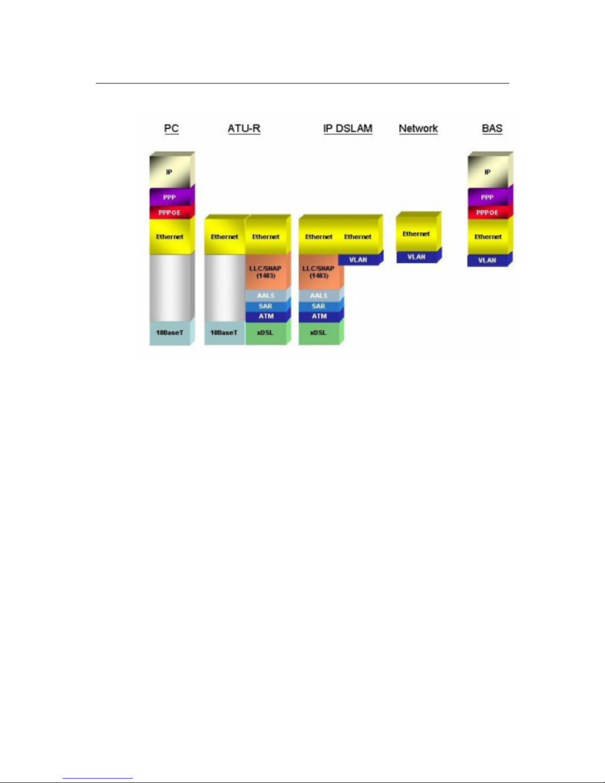
Fig 0-1 & Fig 0-2 display the differences between traditional ATM-based DSLAM
and IPAM-1600s in PPPoE application sample.
Fig 0-1 PPPoE application in Traditional ATM-based ADSL Network
As Fig 0-1 displays, in traditional ATM-based ADSL network, the user
application information is encapsulated by ADSL CPE into ATM cells in
pre-defined VC(Virtual Channel, PVC), and then upstream the ATM cells to
DSLAM via ADSL link. (In this example, the user information (PPPoE
encapsulated) is encapsulated by ATU-R using RFC-1483 Bridge-mode
encapsulation format.)
All the ATM cells belong to the specified VC is concentrated by the DSLAM, and
switched in the ATM network clouds, to the defined destination (ISPs, Offices, ..),
at there the ATM cells and PPPoE frames is resolved by the Broadband Access
Server, and the user application information is serviced.
Introduction
UM1600-2-A 2002
12
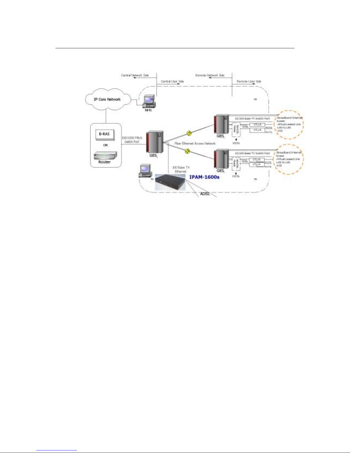
Fig 0-2 PPPoE application in IPAM-1600s with Ethernet-All-The-Way Network
In addition to traditional ATM-based ADSL network. As Fig 0-2 displays, the
user application information is still encapsulated by ADSL CPE into ATM cells in
pre-defined VC (Virtual Channel, PVC), and then upstream the ATM cells to
DSLAM via ADSL link.
In the IPAM-1600s, all the ATM cells belong to the specified VC are
decapsulated back to the original PPPoE encapsulated Ethernet packet (if
VLAN-mode of the specified ADSL port is disabled), or mapped to the
pre-defined Ethernet-VLAN packets (if VLAN-mode of the specified ADSL port is
enabled). IPAM-1600s concentrates all Ethernet-with/without VLAN-tag packets
from 16 ports’ ADSL and uplinks to ISP’s Ethernet-All-The-Way network. The
PPPoE frames will be resolved at Broadband Access Server (BAS), and the
user application information was serviced.
The IPAM-1600s supports ADSL CPE Bridge-mode (RFC-1483 Bridge
mode) only. For performance concern, IPAM-1600s will not act as BRAS to
process user application information directly.
IPAM-1600s provides Ethernet-with/without VLAN tag to ATM-PVC mapping
feature for the ISP to isolate user’s data with security and to provide lots of
service enhancement capabilities. IPAM-1600s supports 2 ATM PVC links for
each ADSL CPE.

Introduction
UM1600-2-A 2002
13
Introduction
General
This chapter will help you understand the function and application of your
SmardDSLAM. It covers
IPAM-1600s Overview
This section describes the overview of your IPAM-1600s. The IPAM-1600s is
cost effective solution for you to complete immediate implementation of multiple
of services in private and public networks.
Difference between IPAM-1600s & IPAM-1600
This section describes the difference between IPAM-1600 & IPAM-1600s.
IPAM-1600s Application
IPAM-1600s can be applied in MTU/MDU/MHU and Ethernet-all-the-way
application.
IPAM-1600s Features
This section describes the features of IPAM-1600s and its specification.

Introduction
UM1600-2-A 2002
14
IPAM-1600s Overview
Today’s bandwidth-hungry application such as Internet access, remote LAN
access, teleconferencing, workgroup and data sharing, telecommuting and
numerous varieties of digital video services are driving today’s demand for
high-speed data network access.
C-Com Corporation designs, develops and markets transmission systems
based on Digital Subscriber Line (DSL) technology for copper wire plant. They
support all contemporary data rates, from 64kbps to multi-megabit symmetric
and asymmetric transmission for voice, video and data communications over a
single copper pair. C-Com access systems link enterprise LANs and Network
Service Providers over private and public networks across the local loop, the
connection between the customer and the first network node.
Using the latest ADSL technology, C-COM IPAM-1600s series offers service
providers a very cost-effective solution for immediate implementation of multiple
services in private and public networks.
IPAM-1600s is one product of the IPAM-1600s series, it acts as a standalone
IP-based DSLAM, which can concentrate and manage up to 16 ADSL lines.
User can use local RS-232 CID and/or remote TELNET/SNMP to manage the
IPAM-1600s directly
Since the ATM backbone coverage is not so general in the real broadband
network environment. Instead of traditional DSLAM system provides ATM uplink
interface, the IPAM-1600s concentrates 16 ports of the ATM over ADSL traffic
which is encapsulated by ADSL CPEs, and maps each user’s data
encapsulated in ATM-PVC to Ethernet-with/without VLAN-tag packet (depends
on the VLAN was enabled or not for the specified ATM ports), and then uplink to
Telco or ISP directly, User can enable VLAN-PVC mapping capability for each
ADSL port independently. The IPAM-1600s acts as bridge for the ADSL ports
without enabling the VLAN-PVC mapping feature. In addition, it also acts as a
manageable SNMP- based layer2 concentrator.
IPAM-1600s provides both Ethernet-VLAN and non-VLAN to ATM-PVC
mapping feature and bridge mode for the ISP to isolate user’s data with security
and to provide lots of service enhancement capabilities. IPAM-1600s supports 2
ATM PVC links for each ADSL CPE.

Introduction
UM1600-2-A 2002
15
Fig 1-1 IPAM-1600s Front View
As Fig 1-1 displays, In the front view of IPAM-1600s, there are several LEDs to
indicate current system and link status and one 10/100 Mega Ethernet interface
for uplink.
Instead of selecting or for centralized management purpose like IPAM-1600s.
The IPAM-1600s can be managed via SNMP, but each IPAM-1600s will cost
one IP address, and the performance of the IPAM-1600s will be little affected
due to CPU usage for the SNMP agent processing.
Fast Ethernet uplink
for uplink
CID
Introduction
UM1600-2-A 2002
16
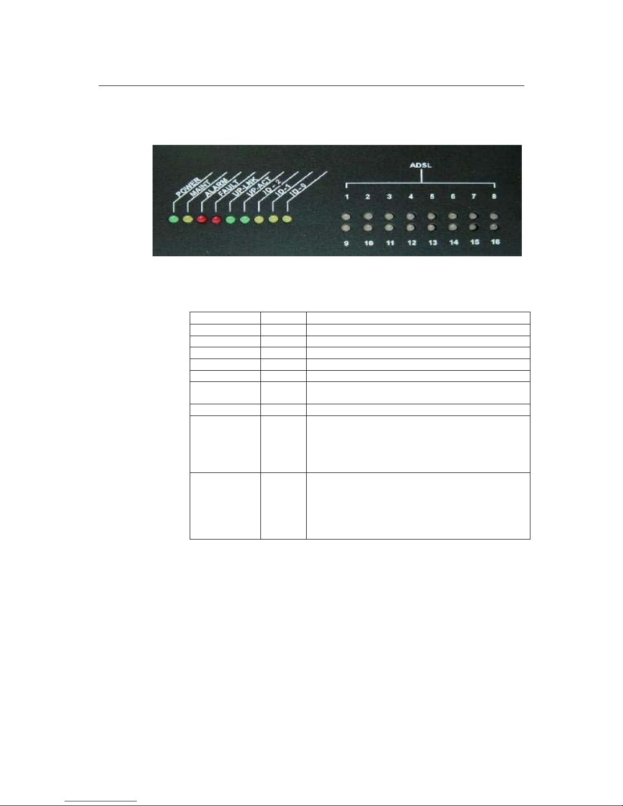
Fig 1-2 displays the LED identification of IPAM-1600s, and Table-1 describes its
color definition and status description.
Fig 1-2 IPAM-1600s LED Identification
Table 1-1 IPAM-1600s LED Description
<LED ID> Color Description
POWER Green Lit when power on
MAINT Yellow Lit when maintance commands were issued
ALARM Red Lit when MJ/MN events happen
FAULT Red Lit when system error is detected
UP-LNK Green Lit when Uplink Ethernet interface was connected
UP-ACT Green Blink when information is transmitted through uplink
Ethernet interface Novemebr
ID-2 Yellow Only applicable for
ID-0 & ID-1 Yellow ID0, ID1 : off, off ------ ID not assigned
ID0, ID1 : on, off ------ ID = 1
ID0, ID1 : off, on ------ ID = 2
ID0, ID1 : on, on ------ ID = 3
*ID = 2 & ID = 3 will not work in IP AM-1600s
ADSL1 –
ADSL16
R/Y/G Lit Red when no carrier is detected in the specified
ADSL link ;
Lit Green when ADSL link is in active state;
Lit Yellow when the specified ADSL link is in
connection training state;
LED off when ADSL link is not in service
Note: Do not power off your IPAM-1600s when LEDs “MAINT”, “ALARM” and
“FAULT” are blinking simultaneously because the system is saving
configuration and updating firmware.
Introduction
UM1600-2-A 2002
17
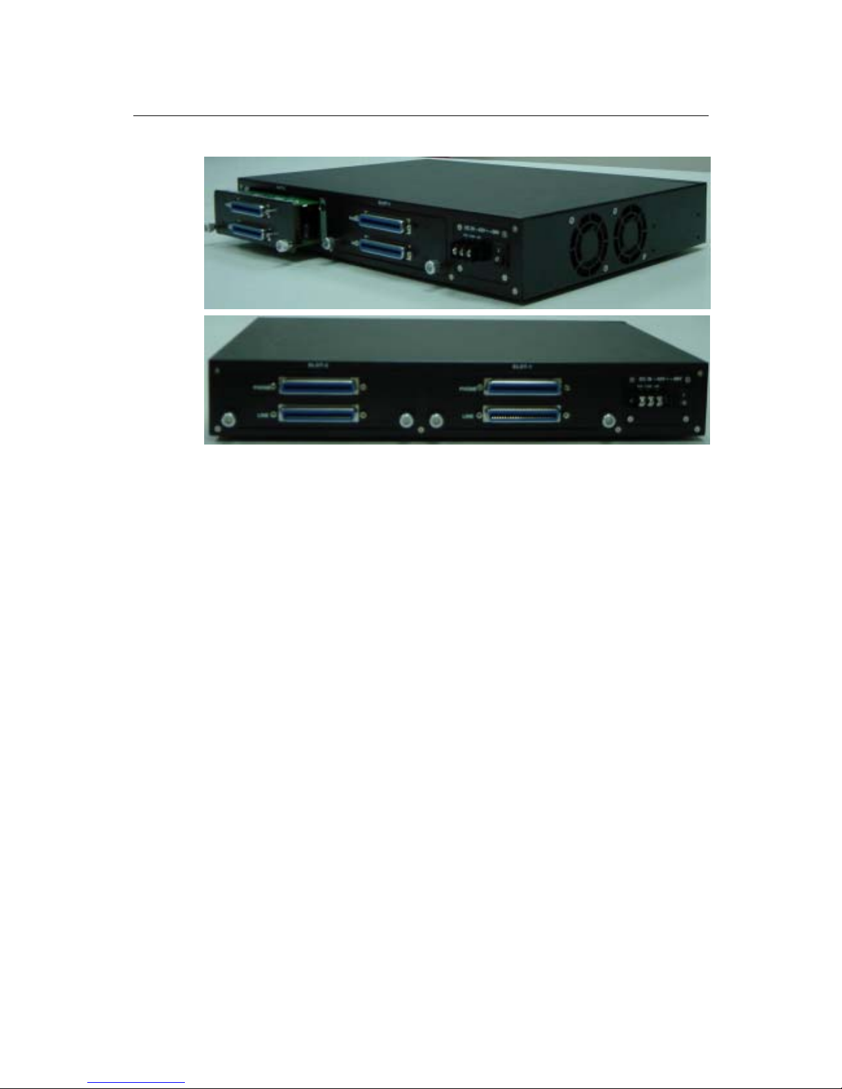
Fig 1-3 IPAM-1600s Rear View
As Fig 1-3 displays, in the rear-panel, there is one power adaptor, both -42V ~
-56V DC or 90V ~ 240V AC power module can be selected. There are two DSL
module slots, each module provides 8-port with built-in POTS-splitter ADSL
module, totally 16 ADSL CPE users can be supported in one IPAM-1600s.
Introduction
UM1600-2-A 2002
18
IP AM-1600s Application
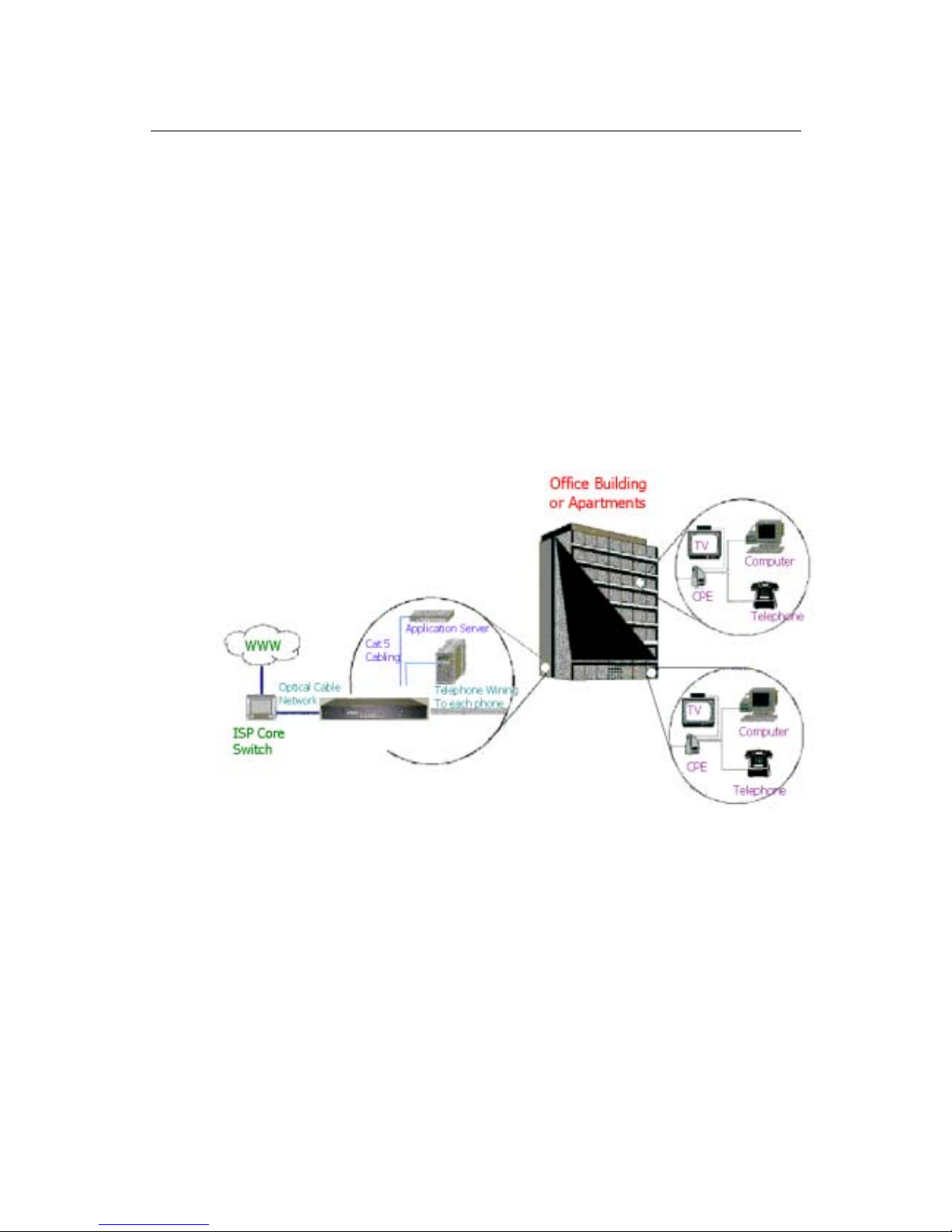
MTU/MDU Application
As Fig 1-4 displays, because of the growth of Internet population, band- width
becomes more and more important for people that live or work in the buildings.
IPAM-1600s enables people inside the buildings to share the expensive uplink
bandwidth and moves the Internet point of presence (POP) into the buildings.
Fig 1-4 IPAM-1600s MTU/MDU Application
Ethernet-All-the-Way application
As Fig 1-5 displays, IPAM-1600S can also be used in Ethernet-All-the-Way
application. IPAM-1600S terminated all the ADSL ATM circuits and converts the
traffic to Ethernet-with/without VLAN- tagged packets. All Ethernet-with/without
VLAN-tag traffic goes directly to ISP internal Ethernet environment, and then is
routed to the Internet.
-
Introduction
UM1600-2-A 2002
19
Fig 1-5 IPAM-1600s Ethernet-All-the-Way Application

Introduction
UM1600-2-A 2002
20
IPAM-1600s Features
VLAN support
The IPAM-1600s supports mapping of Ethernet-VLAN to ATM-PVC feature for
security concern.
Compact design for limited space
The IPAM-1600s occupies 1.5 U of standard Telco rack space. Its compactness
is perfect for collocation and basement installation. With the built-in POTS
splitters, service providers even no need to allocate extra space for POTS
splitter shelves.
Standalone System Design
For the area of less than 16 subscribers, network designer can use IPAM-1600s
to provide service directly.

Introduction
UM1600-2-A 2002
21
IPAM-1600s Specifications
IPAM-1600s
Interface:
ADSL module: 2 modules, each support 8 ADSL links with built-in POTS splitter
LAN Interface: 10/100 TX Ethernet
Power Supply: Built-in –48V DC or 90V-240V AC
Mechanical:
Dimension: 429mm(W) x 300mm(D) x 66mm(H)
Weight: 11lb
Operating position: Horizontal
Environment:
Operating Temperature: 0℃ - +50℃
Storage Temperature: -30℃- +70℃
Operating Relative Humidity (Non-Condensing): 0%-90%
Storage Relative Humidity (Non-Condensing): 0%-95%
Electrical:
Supply Voltage/Current: -42V ~ -56V DC or 90V-240V AC, 50-60Hz, 50 watts
max.
Subscriber Interface:
Can be configure as ANSI T1.413 or G.992.1 (G.DMT).
ADSL G.DMT requirement:
(1)Spectral mask: Meet ITU-T G.992.1 Power Spectrum Density (PSD) mask
requirement. The average PSD within the used pass-band shall be no greater
than –40 dBm/Hz and pass-band ripple shall be no greater than +3.5 dB.
(2)Overhead framing, Embedded Operations Channel (EOC) and ADSL
Overhead Control Channel (AOC)meet ITU-T G.992.1 requirement.
(3)Support "Fast" or "Interleave” mode selectable per port.
(4)Support ITU-T G.992.1 Category I.
(5)Speed: Up-stream 64 kbit/s ~ 1,024 kbit/s, Down-stream: 64 kbit/s ~ 8,064
kbit/s.
(6)Support 2 ATM PVC connections.
Interface:
Uplink Interface : One 10/100-TX Ethernet
Downlink Interface : Three 10/100-TX Ethernet
Power Supply: Built-in –42 to –56V DC or 90V-240V AC

Introduction
UM1600-2-A 2002
22
Mechanical:
Dimension: 429mm(W) x 180mm(D) x 44mm(H)
Weight: 4 lb
Operating position: Horizontal
Environment:
Operating Temperature: 0℃ - +50℃
Storage Temperature: -30℃- +70℃
Operating Relative Humidity (Non-Condensing): 0%-90%
Storage Relative Humidity (Non-Condensing): 0%-95%
Electrical:
Supply Voltage/Current: -42 ~ -56V DC or 90V-240V AC, 50-60Hz, 10 watts
max.
Management
SNMP v2 implementation
MIBs supported:
RFC 1213 – MIB II (System group, Interfaces group)
RFC 2662 (Definitions of Managed Objects for the ADSL Lines)
Proprietary MIB for the IPAM-1600s
Compliance
FCC Part 15, Class B
CE mark

Getting Started
UM1600-2-A 2002
23
Getting Started
2
General
This chapter provides the installation instruction for the hardware installation
and system configuration of your IPAM-1600s so that you can start up quickly. It
includes the following sections:
Unpacking your IPAM-1600s
This section describes how to unpacking your IPAM-1600s, and part number
explanation.
Hardware Installation
This section describes the power connection, loop connection and CID
connection.
Getting Started
UM1600-2-A 2002
24
Unpacking your IPAM-1600s
This section describes how to unpack your IPAM-1600s.
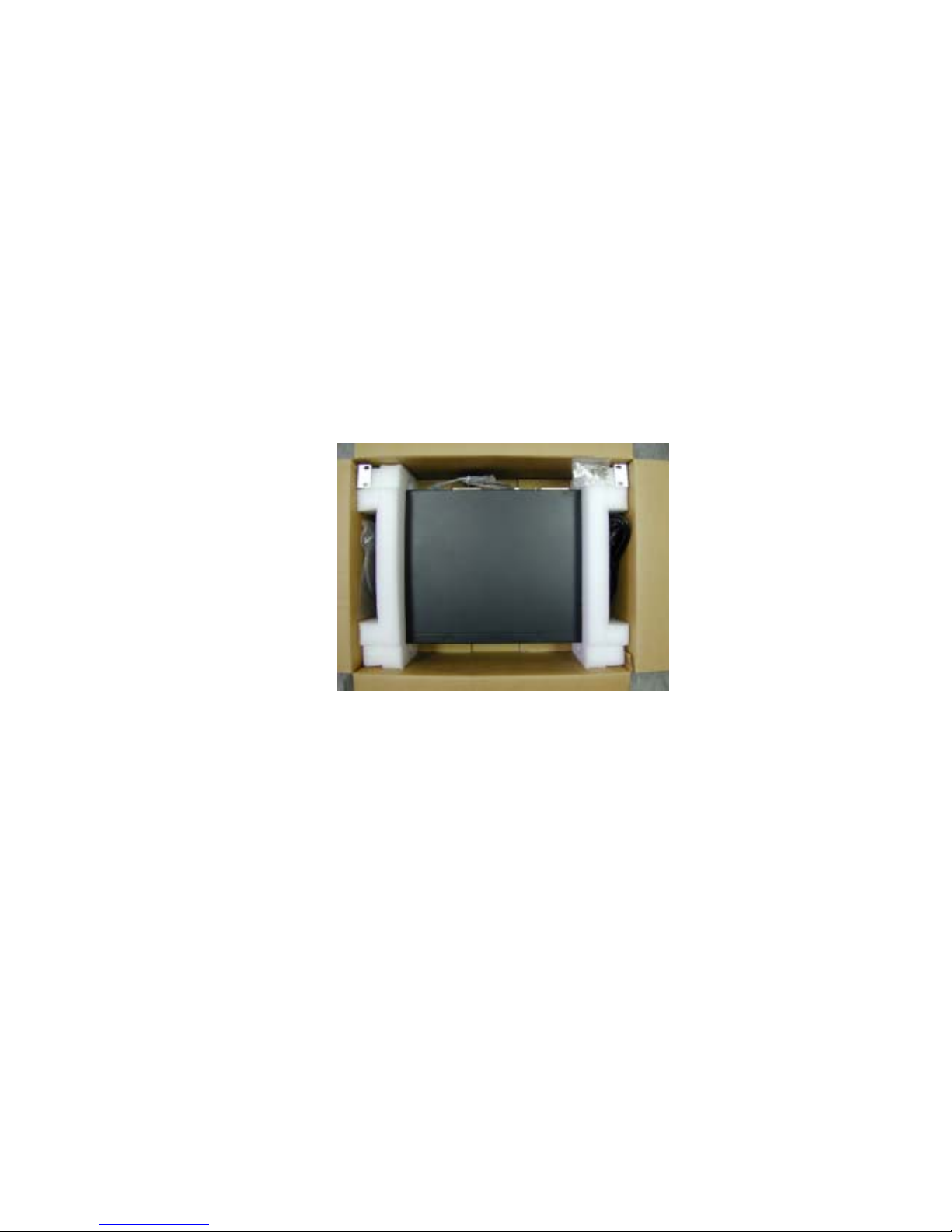
Unpacking your IPAM-1600s
For a box of IPAM-1600s, there may contains the following materials:
Fig 2-1 IPAM-1600s Packing Content
IPAM-1600s box (As Fig 2-1 displays)
IPAM-1600s with two ADSL XCVR modules
Mounting bracket package
RJ-45 Ethernet cable
Power cord (AC power module only)
Documentation in CD or hard copy (optional)
Any other accessories requested at time of ordering.
Check the contents of the package and inspect the unit for any signs of damage.
Report any defects to vendor’s customer service representative. Retain all
packing materials for future shipment.

Getting Started
UM1600-2-A 2002
25
Parts Number Explanation
Parts Number Explanation
All the part number explanation listed as follows tries to help users to identify
the part number by themselves.
IPAM-1600
AM16-xxxxxx-x-xxx = Standard IPAM-1600 Box
xxxxxx = A16GA6: 16 ports ADSL DSLAM, Annex A, two
transceiver modules and POTS splitter equipped
= A08GA6: 8 ports ADSL DSLAM, Annex A, one
transceiver module and POTS splitter equipped
x = A: 90V ~ 240V AC Power
= D: -42 ~ -54V DC Power
xxx
= B01: Black Color without transceiver cable latch
= B03: Black Color with transceiver cable latch
= G01: Gray Color without transceiver cable latch
= G03: Gray Color with transceiver cable latch
= W01: White Color without transceiver cable latch
= W03: White Color with transceiver cable latch
All the part number explanation listed above tries to help users to identify the
part number by themselves. Listed below is the example of part number:
AM16-A16GA6-D-B01 (DC-powered 16 ports black color IPAM-1600 with two
8-port ADSL transceiver modules and POTS splitter built-in)
Hardware Installation
• The IPAM-1600s can be installed in a standard 19-inch rack, by using the
mounting brackets provided.
• Mount the shelf on the rack using the large screws provided.
• Follows the following procedures to connect and wire the system.

Getting Started
UM1600-2-A 2002
26
Safety Instruction
The following is the safety instructions for SmartDSLAM before installation:
1. Read and follows all warning notices and instructions of this user manual.
2. The maximum recommended operating temperature for the SmartDSLAM is
50ºC. Care must be taken to allow sufficient air circulation or space between
units when the SmartDSLAM is installed inside a closed rack assembly and
racks should safely support the combined weight of all SmartDSLAM.
3. The connections and equipment that supply power to the SmartDSLAM
should be capable of operating safely with the maximum power requirements of
the SmartDSLAM. In the event of a power overload, the supply circuits and
supply wiring should not become hazardous.
4. The AC adapter must plug in to the right supply voltage. Make sure that the
supplied AC voltage is correct and stable. If the input AC voltage is over 10%
lower than the standard may cause the SmartDSLAM to malfunction.
5. Do not allow anything to rest on the power cord of the AC adapter, and do not
locate the product where anyone can walk on the power cord.
6. Generally, when installed after the final configuration, the product must
comply with the applicable safety standards and regulatory requirements of the
country in which it is installed. If necessary, consult for technical support.
7. A rare condition can create a voltage potential between the earth grounds of
two or more buildings. If products installed in separate building are
interconnected, the voltage potential can cause a hazardous condition. Consult
a qualified electrical consultant to determine whether or not this phenomenon
exists and, if necessary, implement corrective action before interconnecting the
products. If the equipment is to be used with telecommunications circuit, take
the following precautions:
• Never install telephone wiring during a lightning storm.
• Never install telephone jacks in wet location unless the jack is specially
designed for wet location.
• Never touch uninsulated telephone wires or terminals unless the telephone
line has been disconnected at the network interface.
• Use caution when installing or modifying telephone lines (other than a cordless
telephone) during an electrical storm. There is a remote risk of electric shock
from lightning.
• Do not use a telephone or other equipment connected to telephone lines to
Getting Started
UM1600-2-A 2002
27
report a gas leak in the vicinity of the leak.
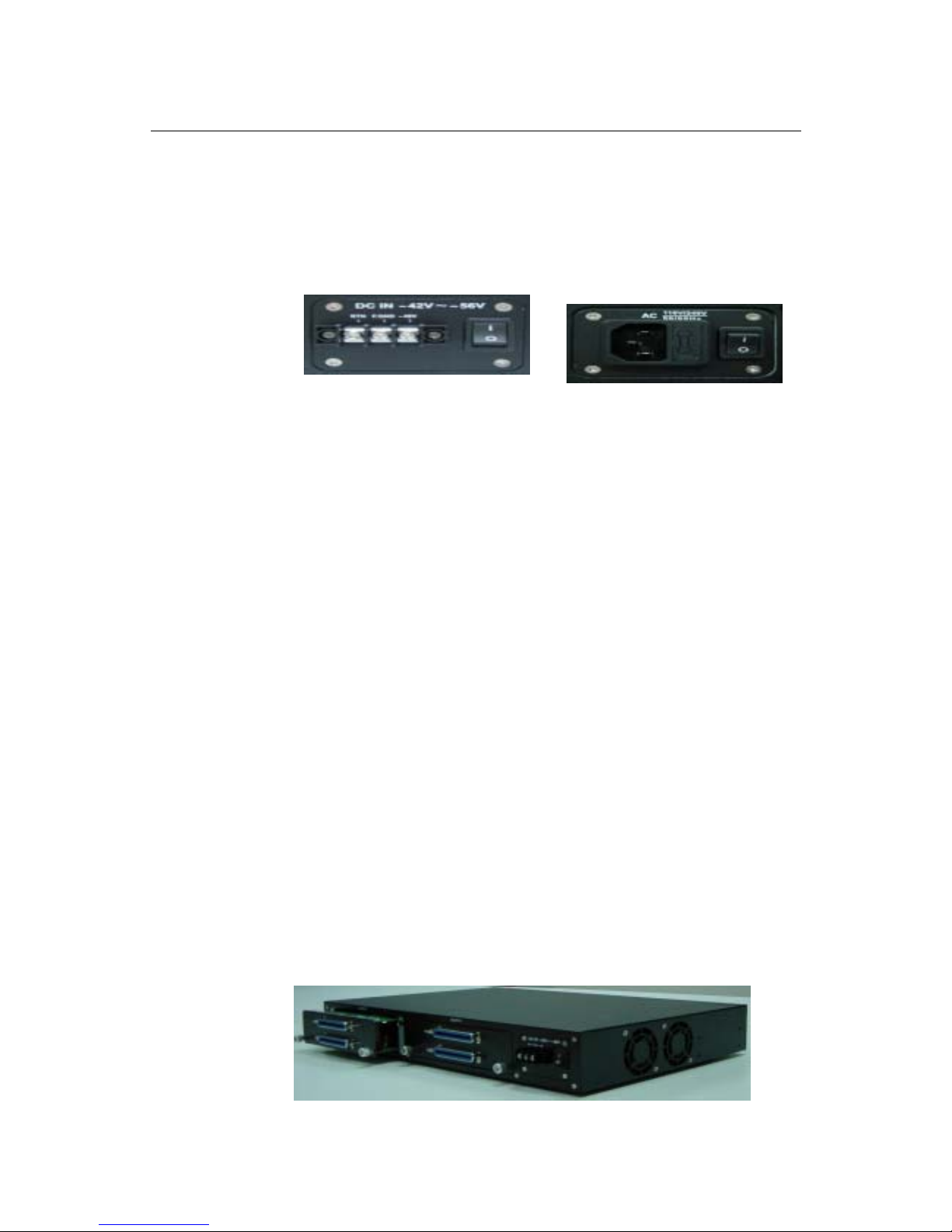
Power Connection
Fig 2-2 DC & AC Power connector
The IPAM-1600s provide both AC and DC power model (As Fig 2-3
displays). Use the following procedures to connect the office power to the
IPAM-1600S system
DC Power
(1) Power off the voltage supply connection. Caution is needed since there may
be dangerous levels of voltage and current present.
(2) Use 16 AWG stranded wire to connect office battery supply leads from the
fuse panel on the equipment rack to the terminal “-48V” on the power
connector of IPAM-1600s.
(3) Use 16 AWG stranded wire to connect RTN leads from the fuse panel on the
equipment rack to the terminals “RTN” on the power connector of
IPAM-1600s.
(4) Grounding the terminals “F.GND” on the power connector of IPAM-1600s.
(5) Power on the voltage supply connection.
AC Power
(1) Use the provided AC power code to connect to the AC power.
(2) Make sure the ground is provided at power inlet.
Loop Connection
Getting Started
UM1600-2-A 2002
28
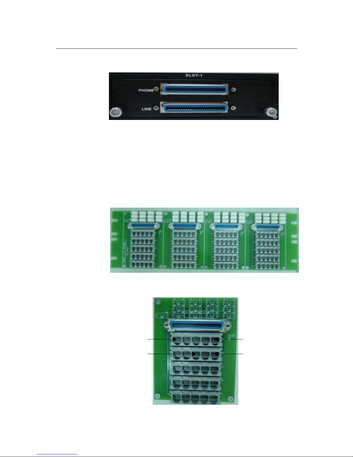
Fig 2-3 IPAM-1600s Rear View & ADSL transceiver module
IPAM-1600s POTS and ADSL Loop Connection
As Fig 2-4 displays, there are two 50-pin female Centronic connectors for
each IPAM-1600s ADSL transceiver module. One of the connectors marked
“LINE” connects the ADSL+POTS loops to connect to ADSL CPEs, whereas the
other connector marked “PHONE” connects to the POTS switch.
For transceiver connector pin assignment, please refer to the appendix-C
Optional MDF Connection Module
Fig 2-4 MDF Patch Panel (Model No: IPAM-MDF-04)
Fig 2-5 Patch Panel (Model No: IPAM-MDF-01)
Port No. 1
Port No. 6
Port No. 5
Port No. 8
 Loading...