

Page 1

Release 1.0 04/22/2005
Page 2

Table of Contents
1.Product specification .............................................................................................................................3
1.1 Specification of MODEM ..........................................................................................................3
1.2. Specification of Bluetooth ........................................................................................................4
2. Hardware Installation Steps ..................................................................................................................5
3.MODEM Driver Installation ....................................................................................................................6
3.1 Windows 98SE ...........................................................................................................................6
3.2 Windows ME...............................................................................................................................7
3.3 Windows 2000 ............................................................................................................................8
3.4 Windows XP ...............................................................................................................................9
3.5 Select Country for MODEM.......................................................................................................10
4.Bluetooth software Installation.............................................................................................................11
4.1 Driver install.............................................................................................................................. 11
5. AT Command......................................................................................................................................12
5.1 Basic AT Commands ................................................................................................................13
5.2 AT& Commands .......................................................................................................................23
5.3 AT\ Commands - Error correction control..................................................................................29
5.4 AT% Commands.......................................................................................................................31
5.5 AT+MS Command ....................................................................................................................34
5.6 AT+F Commands - Fax Support ...............................................................................................36
5.7 AT* Commands - Black List Support.........................................................................................39
5.8 AT# Commands - Voice Modem Support..................................................................................41
5.9 AT#UD Command - Modem Diagnostics Support.....................................................................47
5.10 S-Registers.............................................................................................................................48
Page 3

1.Product specification
1.1 Specification of MODEM
56AZBT is a V.92/V.90 modem designed combine with Class2 Bluetooth support of Azalia riser form
factors. The chipset solution we adopt SmartLink/SmartRiser565 and CSR BlueCore2 single chip
Bluetooth™ system for implement high performance Modem and Bluetooth features.
¾ Modem :
z V.92 (up to 56 Kbps down, 48 Kbps up)
z Quick Connect (V.92)
z Modem on Hold (V.92)
z V.90 (up to 56 Kbps down, 33.6 Kbps up)
z V.34( 4.8 Kbps to 33.6 Kbps)
z V.32 bis (4.8 Kbps to 14.4 Kbps)
z V.23 (75 bps up, 1200 bps down)
z V.22 bis (1200/2400 bps)
z V.21, Bell 103 / Bell 212
z Automode
z V.44/V.42 bis/MNP5 data compression
z V.42/MNP 2-4 error correction
z Hayes AT Command
z TIES escape code
z ACPI power management
¾ Fax :
z Group 3, Class 1
z V.17
z V.29
z V.27 ter
¾ WHQL :
z WLP 2.0 compliant
¾ Voice Features :
z ADPCM voice compression
z Digital Answering Machine
¾ Telephony Services :
z Ring Detection
Page 4

z Wake Up on Ring
z On/Off hook control
z Call progress monitor
z DTMF detection and generation
z Voice/fax/modem distinction
z Caller ID (optional)
¾ Video Conferencing :
z V.80/H.324 interface support
¾ International Approvals :
z Single board layout for multiple country certification: FCC, CTR21, JATE and others
¾ Operating System Support :
z Windows (XP, 2000, ME, 98SE, 98, 95, NT4), Linux
¾ Diagnostic Tool :
z Modem Helper
1.2. Specification of Bluetooth
¾ Features
z Complete 2.4GHz radio transceiver and baseband
z Bluetooth ™ version 1.1 compliant (upgradable to ver.1.2)
z Bluetooth ™ Class 2 operation
z Park, Sniff, Hold and Sleep low power modes
¾ General
z Data Transmission Rate up to 723 kbps (asynchronous)
z Link Distance better than 10 meters (33 feet) in free space
¾ General
z Modulation : Frequency Hopping Spread Spectrum (FHSS) with Gaussian Frequency
Shift Keying (GFSK)
z Frequency Range : 2.40GHz– 2.4835GHz (ISM Band)
z RF Channels : 79 channels for USA, Japan, and Europe (except France)
z RF Output Power : +4 dBm ma x. , Class 2 (upgradeable to 20dBm)
z Sensitivity : Better than –[email protected]% BER
z Max. Input Level : - 20dBm
¾ Baseband
z Link Mode : ACL & SCO link supported
Page 5

z Network Capabilities : Piconet : point –to- point & point-to-multipoint and Scatternet
supported
z Security :
9 Initialization: 4-digit PIN code
9 Authentication: Security Mode 2 support
9 Encryption: 128-bit Data Encryption support
z Data Packets : DM1/DH1, DM3/DH3, DM5/DH5
¾ Operating System Support :
z Windows XP/2000/ME/9x
2. Hardware Installation Steps
1. Turn computer power off and unplug your computer from the power supply.
2. Remove the computer cover.
3. Insert Modem/Bluetooth combo card into MDC 1.5 connector of mother board.
4. Plug one end of the telephone cable into MODEM “LINE” jack . Plug the other end of the telephone
cable into wall phone jack.
5. Turn computer power on.
Page 6
3.MODEM Driver Installation
3.1 Windows 98SE
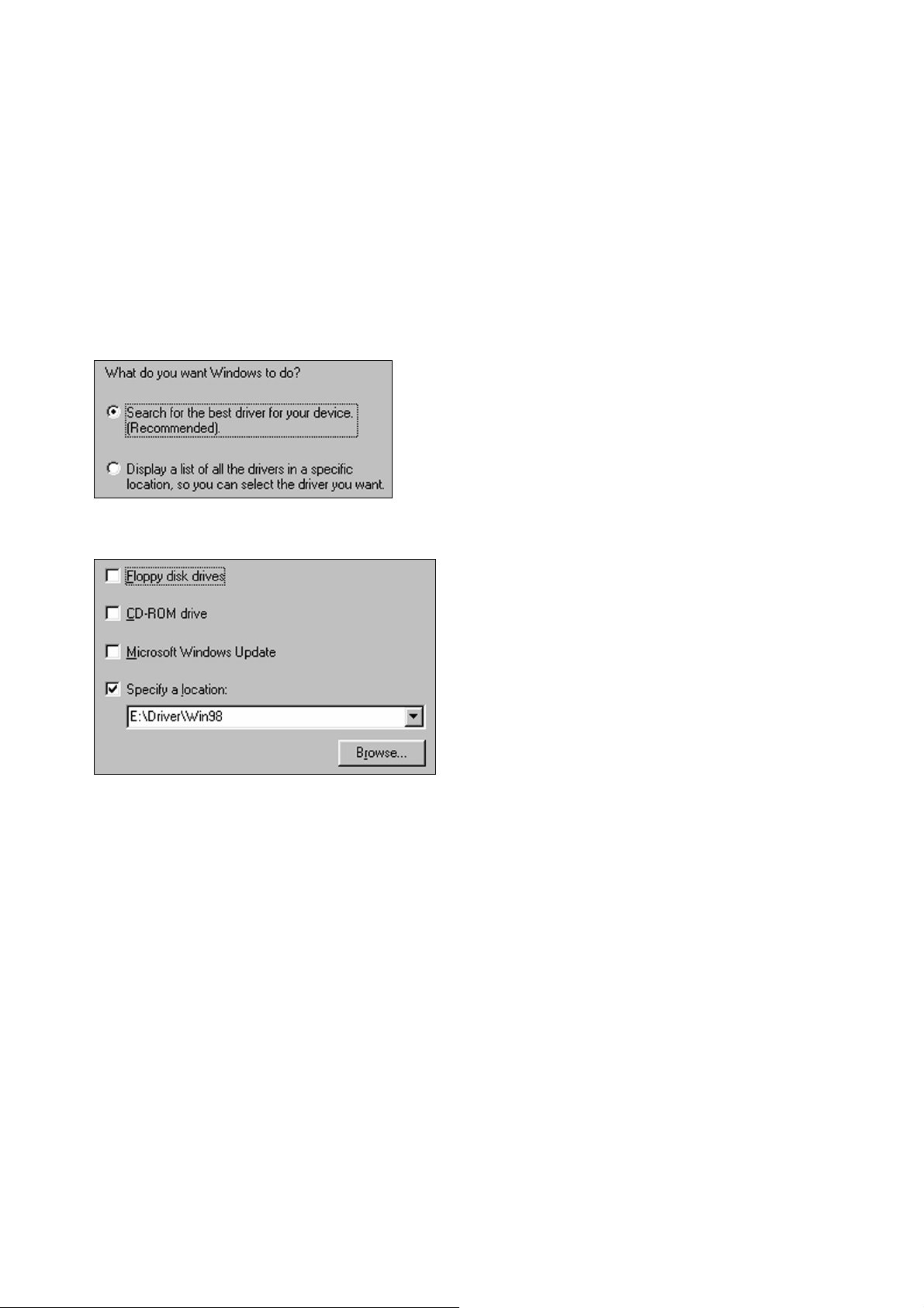
1. Boot the system. System will detect a new Device and request you to install its driver. Click [ Next ]
button.
2. In the new dialog box, you have two choices to install a driver. The default choice is “Search for the
best driver for your device” and click [ Next ] button
3. Choose “Specify a location”.
4. Insert the driver CD into the CD-ROM device. Click Browse and choose the CD-ROM Location (Ex:
E:\Driver\Win98)
5. Windows 98 will copy the files into your hard disk. Click [ Finish ] button.
Page 7
3.2 Windows ME
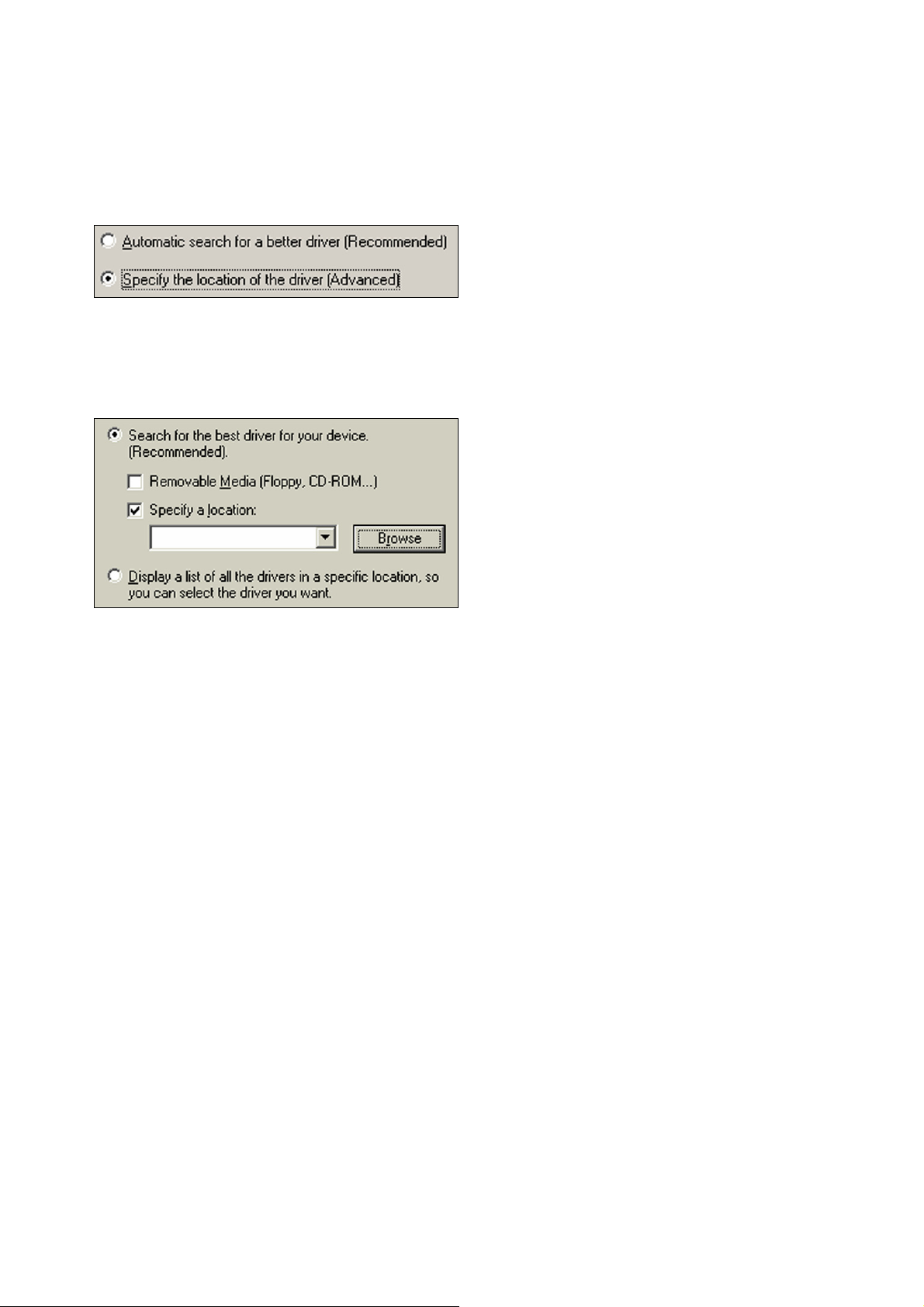
1. Boot the system. System will detect a new Device and request you to install its driver.
2. Choose “Specify the location of the driver”. Click [ Next ] button.
3. Choose “Specify a location”.
4. Insert the driver CD into the CD-ROM device.
Click Browse and choose the CD-ROM Location (Ex: E:\Driver\WinME).
5. Click [ Finish ] button. Repeat step2, step3, step4 and step5 once.
6. Windows ME will copy the files into your hard disk. Click [ Finish ] button
Page 8
3.3 Windows 2000
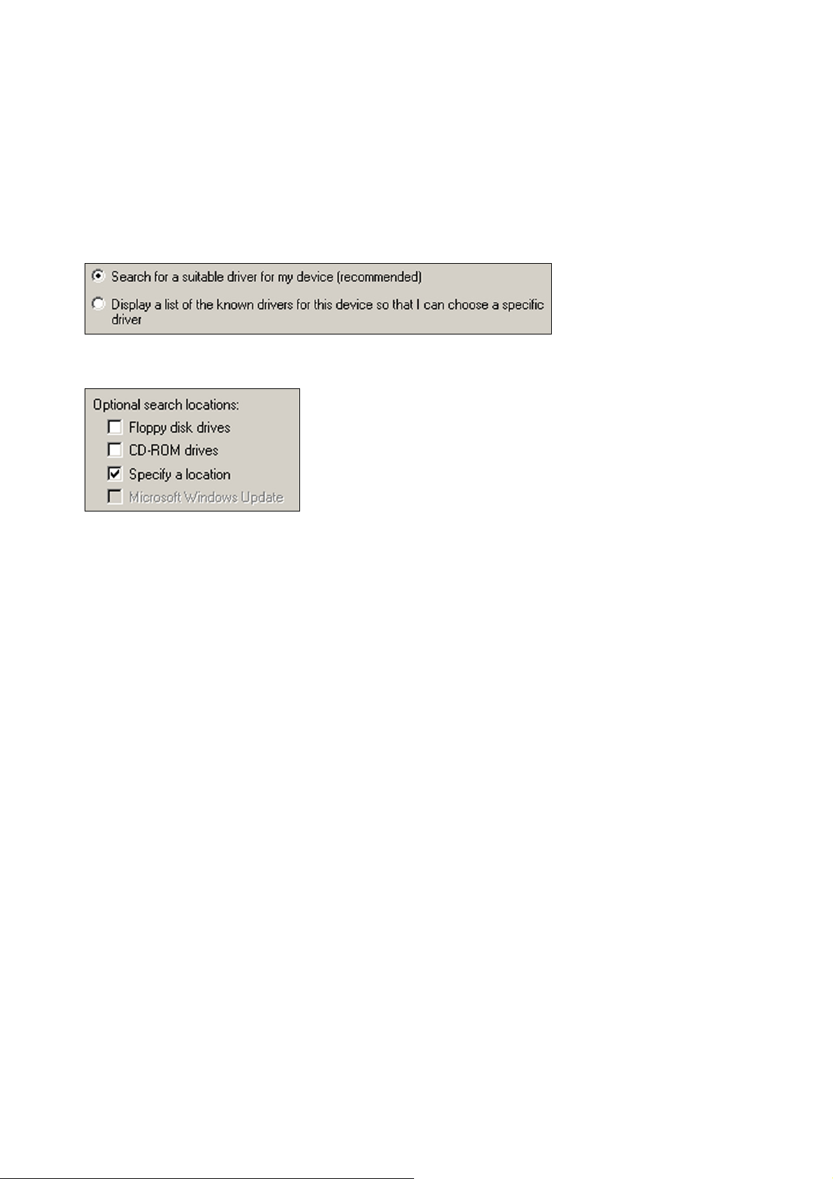
1. Boot the system. System will detect a new Device and request you to install its driver. Click [ Next ]
button.
2. In the new dialog box, you have two choices to install a driver. The default choice is “Search for a
suitable driver for my device” and click [ Next ] button.
3. Choose “Specify a location”. Click [ Next ] button.
4. Insert the driver CD into the CD-ROM device. Click Browse and choose the CD-ROM Location (Ex:
E:\Driver\WIN2K-XP).
5. Windows 2000 will copy the files into your hard disk. Click [ Finish ] button
Page 9
3.4 Windows XP
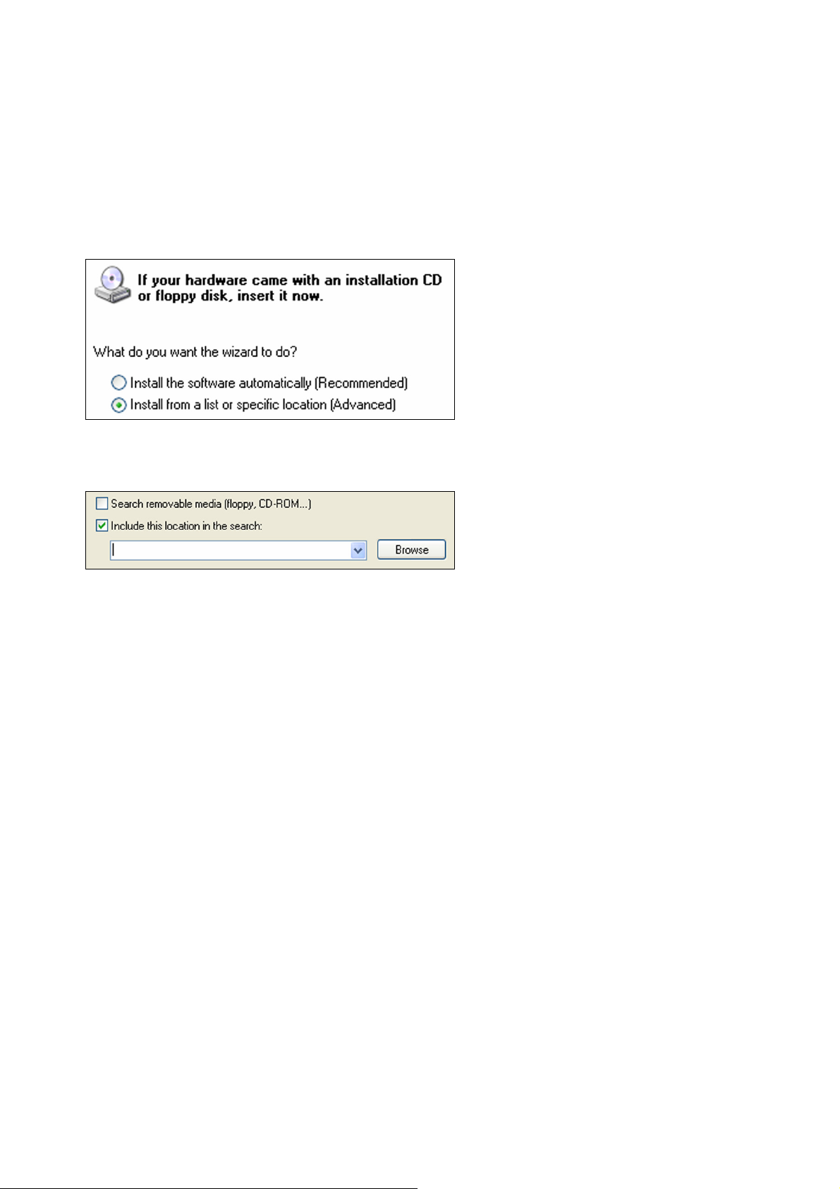
1. Boot the system. System will detect a new Device and request you to install its driver.
2. In the new dialog box, you have two choices to install a driver. Choose “Install from a list or specific
location”. Click [Next] button.
3. Choose “Include this location in the search”.
4. Insert the driver CD into the CD-ROM device. Click Browse and choose the CD-ROM Location (Ex:
E:\Driver\WIN2K-XP). Click [Next] button.
5. Windows XP will copy the files into your hard disk. Click [Finish] button
Page 10
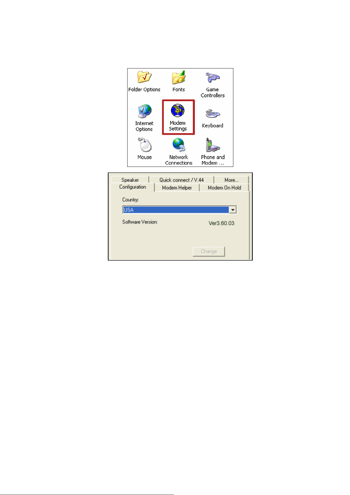
3.5 Select Country for MODEM
Control Panel Æ Modem Settings
Page 11
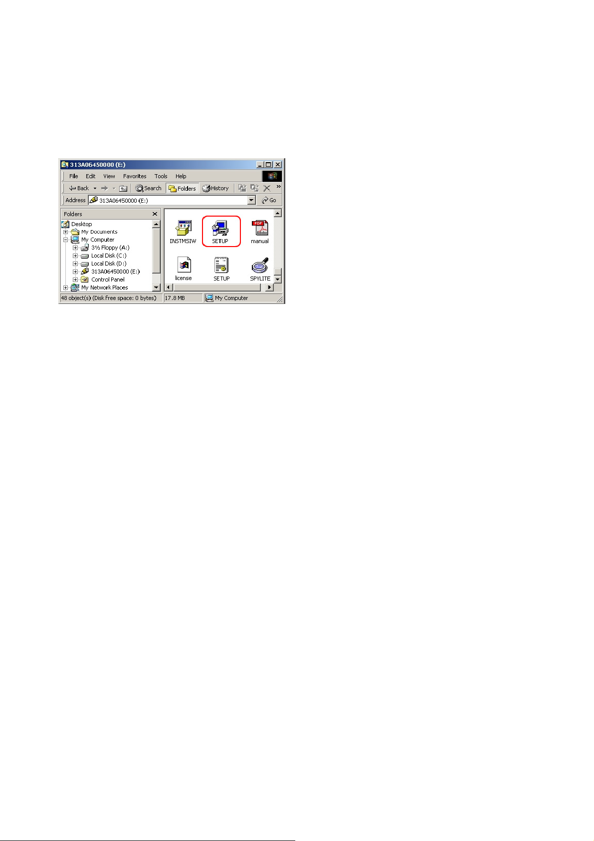
4.Bluetooth software Installation
4.1 Driver install
1. Insert the driver CD ,then Run the setup.exe from CD ROM
,as figure below.( this driver-utility support Win98SE/ME/2000/XP)
2. This driver-utility will provide a InstallShield Wizard for installation.
3. Instillshield Wizard will auto reboot system after installation is completed .
Page 12

5. AT Command
Modem operation is controlled by AT commands. These AT commands include the following:
1. Basic AT commands, for example ATDT123
2. Extended AT Commands for example AT&E,AT\A,AT%C,AT+MS
3. S-Register commands, for example ATS32=8
4. Fax Class 1 commands, for example AT+FTM
5. Voice commands, for example AT#VTX
The command syntax and operation guidelines for each command category are described in the following
sections.
A command line is a string of characters sent from a DTE (Terminal or Data Terminal Equipment) to the
DCE while the DCE is in command state. Command lines have a prefix, a body and a terminator. The prefix
consists of the ASCII characters AT or at. The body consists of printable ASCII characters. Space
characters other than <CR> (See register S3), and <BS> (See register S5) are ignored. <CR> is command
terminator.
Characters preceding the AT prefix are ignored.
AT Command Guidelines
6. Basic AT commands consist of single ASCII characters, which may be preceded by a prefix character, for
example &, and followed by a decimal number, for example AT&W1.
7. Missing decimal parameters are interpreted as 0. For example, if you type ATH, the command ATH0 is
assumed.
8. Fax commands are preceded with the +F characters and terminated by semicolon (;) or <CR> character.
9. The modem supports editing command lines by recognizing the <BS> character.
10. The AT command sequence may be followed by any number of commands in sequence, with the exception
of commands Z, D or A, where all characters following on the same command line will be ignored.
11.
When a syntax error is found in the command line, an ERROR response will be returned to the DTE.
Execution of commands D and A will be aborted if another character is entered before completion of the
handshake.
12. When the modem has entered on-line data mode, it is possible to break the data transmission in order to
issue more AT commands. This is done by the DTE sending a sequence of three escape characters
(defined in S2, "+" by default). The maximum time allowed between receipt of the last character of the three
and the sending of the OK code to the DTE is defined in S12.
AT Command Set
The modem will comply with the commands listed below. Parameters applicable to each command are listed below.
Default factory configuration settings are marked by an asterisk *.
Features marked with (-) are not yet available in the current version.
Page 13

5.1 Basic AT Commands
A/ Re-execute Command
The modem repeats the last command line sent by the DTE. Usually used for re-dialing.
Note: This command should not be terminated by <CR>.
A Answer
The modem will go off-hook and attempt to answer an incoming call. Upon successful completion of
handshake, the modem will go on-line in answer mode.
Notes:
If +FCLASS=0 is selected, the modem will enter the connect state after exchanging carrier with the
remote system. If no carrier is detected within the period specified in S7, the modem hangs up. Any
character entered while connecting will abort the connection process.
If +FCLASS=1, the modem will go off-hook in V21 answer mode. It will generate the V21 2100 Hz
answer tone for 3 +/- 0.5 seconds, and following a delay of 70 ms, will proceed as if the +FTH=3
command were issued. At any stage up to (but excluding) the +FTH=3 command state, any character
will abort the communication.
If +FCLASS=8 (#CLS=8), the modem will go off-hook and a voice session will take place.
Related S-Reg: S0
Bn CCITT Control
B0 Connect at V.22 1200 bps
Result codes:
OK n=0
Error Otherwise
Dn Dial
Directs the modem to go on-line, dial according to the string entered, and attempt to establish a
connection.
The Dial String may consist of any of the characters described below:
Page 14

*
T Tone dialing (first character in the string)
P Pulse dialing (first character in the string)
L Redial last dialed number (first character in the string)
0-9 Digits 0 to 9.
* Asterisk (tone only)
# Hash (tone only)
W Wait for dial tone; the modem will wait for dial tone before dialing the digits
following "W". S6 register will be used for timeout. (X3 or higher)
, (Comma), Pause for the time specified by S8 before resuming the dialing
(Semicolon) Return to command mode after dialing. This allows the user to issue
additional AT commands while remaining off-hook. Actual call progress will be
entered only after a dial command issued without the ¡§;¡¨ terminator.
S=n Dial the number stored in the directory; n=0-3 (see &Z).
! Flash; The modem will go on hook for a time defined by S24.
@ Wait for silence; The modem will wait for at least 5 seconds of silence before
resuming the dialing. If no such silence is detected before the expiration of the call
abort timer (S7), the modem will terminate with NO ANSWER response (or BUSY if
applicable). If answer tone arrives during execution of this parameter, the modem
handshakes. (X3 or higher)
(),< > (space) String format characters - ignored
<i> any other character - ignored.
Notes:
If +FCLASS=0 is selected, the modem will attempt to connect with another data modem. The modem
will use the time period specified in S6 and S7 as time-outs in the handshake process. If a timeout
expires, the modem will go on-hook and respond with NO CARRIER response. The command will be
aborted in progress is a DTE character is entered before completion of the handshake.
If +FCLASS=1, the modem will attempt to connect with a fax machine (or modem) by entering the
HDLC V21 channel 2 receive state (as if +FRH=3 had been issued).
Page 15

The command will be aborted upon receipt of a DTE character if the modem has not finished dialing.
In this case the modem will go on-hook and return to command mode responding with NO CARRIER
En
*
message. If the modem has finished dialing, It proceeds as if +FRH=3 command has been issued.
If +FCLASS=8 (#CLS=8), the modem will go off-hook in V21 answer mode. It will decide (based on
timers) when the other side answers in voice and a voice session will take place.
Related S-Reg: S5,S6,S7,S16,S22,S28,S56
Set local echo
The modem enables/disables echo of characters to DTE.
Parameter value is written to S13.
E0 Disable command echo.
E1 Enable command echo.
Result codes:
OK n=0 or 1
Error Otherwise
Related S-Reg: S13
Hn
*
In Identification/Information
Set ON/OFF hook
H0 Modem hangs up (goes on-hook).
H1 Modem goes off hook.
Result codes:
OK n=0 or 1
Error Otherwise
I1 Modem Name, Vendor Name, Modem Version,
for example :
Page 16

ModemX
ModemWorks Ltd.
Ver 1.10
I2 SW Provider /SW Version, for example
Smart Link Ltd.
Ver 1.20
I3 Chipset Vendor/Chipset ID, for example
Chip Vendor Ltd.
XY4220
I4 Modem active profile for example,
Active Profile:
S00=000 S01=000 S02=000 S03=000 S04=000 S05=000 S06=000 S07=000
S08=000 S00=009 S10=000 S11=000 S12=000 S13=000 S14=000 S15=000
S16=000 S17=000 S18=000 S01=019 S20=000 S21=000 S22=000 S23=000
S24=000 S25=000 S26=000 S27=000 S28=000 S29=000 S30=000 S31=000
S32=000 S33=000 S34=000 S35=000 S36=000 S37=000 S38=000 S39=000
S40=000 S41=000 S42=000 S43=000 S44=000 S45=000 S46=000 S47=000
I5 Stored profile 0
Active Profile 0:
(Same format as above)
I6 Stored profile 1
Active Profile 1:
Page 17

(Same format as above)
I7 Display stored pone numbers
(See &Z command)
Ln
*
Speaker volume
Select speaker volume.
L0 Low
L1 Low
L2 Medium
L3 High
Result codes:
OK n=0-3
Error Otherwise
Related S-Reg: S30
Mn
*
Speaker control
Select when the speaker is On/Off.
M0 Speaker always OFF
M1 Speaker ON from start of dialing until receiving carrier
M2 Speaker always ON
M3 Speaker OFF from end of dialing until receiving carrier
Result codes:
OK n=0-3
Error Otherwise
Related S-Reg: S29
Page 18

Nn
Automode control
Enable/Disable Automode detection.
N0 Automode detection disabled. A subsequent handshake will be conducted
according to the contents of S32.
N1 Automode enabled. A subsequent handshake will be conducted according to the
*
Result codes:
OK n=0 or 1
Error Otherwise
Related S-Reg: S31
On Returns to on-line data mode
This command is normally used to connect the DTE back after an escape (+++) has been issued.
Automode algorithm.
O0 Return to on-line data mode.
O1 Return to on-line data mode, retrain first.
Result codes:
OK n=0-1
Error Otherwise
P Pulse dialing
Forces pulse dialing. Applies to subsequent dialing commands.
This command holds until the next T dial modifier or T command is received.
The modem will go off hook and attempt to answer an incoming call. Upon successful completion of
handshake, the modem will go on-line in answer mode.
Related S-Reg: S16
Q * Quiet result codes control
Page 19

Q0 Enable sending result codes to DTE.
Q1 Disable sending result codes to DTE.
Result codes:
OK n=0 or 1
Error Otherwise
Related S-Reg: S14
S Read/Write S-Register
This command has a few derivatives:
Sn=v Sets the value v (decimal) to S-register n (v=0-255)
Sn? Displays the value of S-register in decimal format (3 digits)
Note: Some registers are read-only
Result codes:
T Tone dialing
Forces tone dialing. Applies to subsequent dialing commands.
This command holds until the next T dial modifier or T command is received.
This command changes S14 to reflect the current dialing mode.
Related S-Reg: S16
Vn
Verbose/Numeric result codes
OK All parameters valid
Error Invalid S register or value. Trying to write to a read-only register
Select the time of result messages sent to the DTE.
For a list of result codes and verbal messages see X command.
V0 Short form (numeric) result codes to be sent to DTE.
Page 20

*
Xn Extended result codes
V1 Long form (verbose) result codes to be sent to DTE.
Result codes:
OK n=0 or 1
Error otherwise
Related S-Reg: S15
Select the subset of result codes to be used by the modem to the DTE.
If the modem is in fax mode (+FCLASS=1), the only message sent to indicate connection is
CONNECT without a speed indication.
X0 Supported messages: OK, CONNECT, RING, NO CARRIER and ERROR, Blind
call enabled.
X1 Supported messages: OK, CONNECT xxxx, RING, NO CARRIER and ERROR,
Blind call enabled.
X2 Same as X1 + NO DIAL TONE message, Blind call disabled
X3 Same as X1 + BUSY message, Blind call enabled.
* X4 All messages supported, Blind call disabled (see list below).
Notes:
W,@ dial modifiers are ignored in X1, X2
S6 (Wait before dial) is ignored in X2, X4 if no W is specified in dial string
S6 is set to 0 means a blind call
Page 21

Table 1 - Result Codes
Result Message X0 X1 X2 X3 X4
Code
0 OK * * * * *
1 CONNECT * * * * *
2 RING * * * * *
3 NO CARRIER * * * * *
4 ERROR * * * * *
5 CONNECT 1200 1 * * * *
6 NO DIAL TONE 3 3 * 3 *
7 BUSY 3 3 3 * *
8 NO ANSWER 3 3 3 * *
9 CONNECT 0300 1 * * * *
10 CONNECT 0600 1 * * * *
11 CONNECT 2400 1 * * * *
12 CONNECT 4800 1 * * * *
13 CONNECT 7200 1 * * * *
27 CONNECT 9600 1 * * * *
14 CONNECT 12000 1 * * * *
15 CONNECT 14400 1 * * * *
16 CONNECT 16800 1 * * * *
17 CONNECT 19200 1 * * * *
18 CONNECT 21600 1 * * * *
19 CONNECT 24000 1 * * * *
20 CONNECT 26400 1 * * * *
Page 22

66 COMPRESSION: - * * * *
CLASS 5
67 COMPRESSION: - * * * *
V.42BIS
69 COMPRESSION: - * * * *
NONE
76 PROTOCOL: NONE - * * * *
77 PROTOCOL: LAPM - * * * *
78 PROTOCOL: MNP - * * * *
1021 MODULATION: V.21 - * * * *
1022 MODULATION: V.22 - * * * *
1032 MODULATION: V.32 - * * * *
1034 MODULATION: V.34 - * * * *
1103 MODULATION: B103 - * * * *
1122 MODULATION: - * * * *
V.22BIS
1132 MODULATION: - * * * *
V.32BIS
1134 MODULATION: - * * * *
V.34BIS
1212 MODULATION: B212 - * * * *
+F4 +FCERROR * * * * *
<*> message will be generated when n has been selected
<i> message will be replaced by message <I> when n has been selected
<-> message will not be generated when n has been selected.
Related S-Reg: S56
Page 23

Yn
Select default configuration
*
Zn Select user defined configuration
Select the default user defined configuration.
Note: The default configuration is not loaded by Yn (See Zn)
Y0 Select user template 0
Y1 Select user template 1
Y2 Select factory setting 0
Y3 Select factory setting 1
Related S-Reg: S161
Select the user defined configuration.
Z0 Select default user template (as defined by Yn)
Z1 Select user template 0
Z2 Select user template 1
Z3 Select factory setting 0 (&F0)
Z4 Select factory setting 1 (&F1)
Result codes:
OK n=0-5
Error Otherwise
Related S-Reg: S59
5.2 AT& Commands
&An Connect message format
Select the format of the CONNECT message.
Page 24

*
&A0 no extra messages besides CONNECT xxxxx
&A1 Add Modulation indicator:
V.21/ V.22/ V.22BIS/ V.32/ V.32BIS/ V.34/ V.34BIS/ B103/ B212
For example:
Modulation: V.34
&A2 Add Error Detection Protocol and Data Compression indicators.
For example:
Protocol: LAPM/MNP/NONE
Compression: CLASS 5/V.42BIS/NONE
&A3 Add Modulation Indicator + Error Detection Protocol + Data Compression indicators (see above).
&Cn
*
&Dn
Related S-Reg: S70, S71
Control Carrier Detect (CD,RLSD) behavior
Controls the RLSD output behavior.
&C0 RLSD is assumed to be ON all the time
&C1 RLSD follows the carrier state
Result codes:
OK n=0 or 1
Error Otherwise
Related S-Reg: S60
Controls DTR behavior (NA)
Controls the DTR output behavior.
Note: This command is supported for compatibility.
It has no significance in Modio environment.
Page 25

*
&D0 DTR is taken to be ON all the time
&D1 DTR drop causes entry to command mode without disconnect
&D2 DTR follows DTR circuit definition
&D3 DTR drop causes software reset (as in Z0)
Result codes:
OK n=0-3
Error Otherwise
Related S-Reg: S63
&En
*
&Fn Sets factory configuration
Connect message speed source
Select the requested source for the speed field in the CONNECT message.
&E0 DCE Speed
&E1 DTE Speed
Note: Since a virtual port is involved, the DTE is not bound by any UART limitation, and may be
theoretically set as high as 921600.
DTE speed is supported for compatibility only. It bears little significance in Modio environment.
Related S-Reg: S71
Select one of the factory settings.
&F0 Select factory setting 0
&F1 Select factory setting 1
Result codes:
OK n=0-1
Error Otherwise
Related S-Reg: S59
Page 26

&Hn
Sets flow control
*
&Kn Same as %Cn
&Pn * Set pulse dial make/break ratio
Select the user defined configuration.
&H0 Flow control disabled (NA)
&H1 HW flow control RTS/CTS (emulation)
Result codes:
OK n=0-1
Error Otherwise
Related S-Reg: S62
&P0 US & Canada 39%/61% (10 pps)
&P1 UK & Hong Kong 33%/67% (10 pps)
&P2 Same as 0, except at 20 pps
&P3 Same as 1, except at 20 pps
Result codes:
OK n=0-3
Error Otherwise
Related S-Reg: S28
&Rn Controls RTS behavior
Controls the RTS output behavior.
Note: This command is supported for compatibility.
It has no actual effect
&R0 RTS ignored
Page 27

&R1 Modem receives data only on RTS (NA)
Result codes:
OK n=0 or 1
Error Otherwise
Related S-Reg: S61
&Sn Controls DSR behavior
Note: This command is supported for compatibility.
It has no actual effect.
&S0 DSR override (is assumed to be ON all the time)
&S1 DSR follows circuit definition
Result codes:
OK n=0 or 1
Error Otherwise
Related S-Reg: S64
&V Display Active profile, Stored Profiles, Stored Phone Numbers (Equivalent to I4-I7 combined)
&Wn Writes current configuration
&W0 Write to template 0
&W1 Write to template 1
Result codes:
OK n=0-1
Error Otherwise
Written to registry.
&Zn Stores dial string
Page 28

Stores/Displays dial string (up to 47 characters)
&Zn=s Store dial string (n=0-4)
&Zn=L Store the last dialed string (n=0-4)
&Zn? Display the nth string
&ZL? Display the last dialed string
Written to registry.
Page 29

5.3 AT\ Commands - Error correction control
\An
*
\Bn Transmit break to remote (-)
Maximum MNP block Size
\A0 64 characters maximum block size
\A1 128 characters maximum block size
\A2 192 characters maximum block size
\A3 256 characters maximum block size
Result codes:
OK n=0-3
Error Otherwise
Related S-Reg: S<basereg+1> of V.42 registers
In non-error correction mode, the modem will transmit a break signal to the remote
modem with a length of n*100ms. If a number above 9 is entered, 9 is used.
Result codes:
OK if connected in data modem mode
Error if not connected or if connected in fax modem mode
\Kn Break Control (-)
Controls the response of the modem to a break received from DTE or a remote modem
or the \Bn command.
The behavior parameter is written to Sxx
\K0 Enter on-line command mode, no break sent to remote modem
\K1 Clear data buffers and send break to remote modem
\K2 Same as 0
Page 30

\K3 Send break to remote modem immediately
\K4 Same as 0
* \K5 Send a break to remote modem in sequence with transmitted data
Related S-Reg: S<basereg+x> of V.42 registers
Result codes:
OK n=0-5
Error Otherwise
\Nn Error correction operating mode
\N0 Normal (Speed buffering) - No error correction
\N1 Direct (pass-through) 128 characters maximum block size
\N2 Reliable (error correction) mode. The Modem will attempt LAPM and then MNP
* \N3 Auto reliable mode. Same as \N2, but will fall back to Normal
\N4 LAPM error correction mode only, hang up upon failure.
\N5 MNP error correction mode only, hang up upon failure.
Result codes:
OK n=0-5
Error Otherwise
Related S-Reg: S<basereg> of V.42 registers
Page 31

5.4 AT% Commands
%Cn
*
%En
Compression control
%C0 Disable data compression
%C1 Enable MNP5 data compression
%C2 Enable V.42bis data compression
%C3 Enable MNP5/V.42bis data compression
Result codes:
OK n=0-3
Error Otherwise
Related S-Reg: S<basereg+2> of V.42 registers
Line quality monitor control
*
Controls whether or not the modem will automatically monitor
the line quality and request a retrain (%E1), or fall back when
quality is insufficient or fall forward when line quality
improves (%E2).
%E0 Disable line quality control
%E1 Enable line quality control and auto retrain
%E2 Enable line quality control and fallback/forward
Result codes:
OK n=0-3
Error Otherwise
Related S-Reg: S39
%Tn Test
mode
Auxiliary Registers Setup
Page 32

%T23
-
%T32
%T33
%T34
%T35
-
Generate DTMF 0-9
Generate DTMF *
Generate DTMF #
Generate DTMF A-D
%T38
%T39
%T40
%T41
%T42
%T90
%T91
%T90
%T91
%T90
V.25 Answer Tone (2100Hz)
V.25 Calling Tone (1300Hz)
Fax Calling Tone (1100Hz)
1800Hz Guard Tone
V.21 Channel 1 mark origin
V.21 Channel 1 mark answer
V.23 Channel mark origin
V.23 Channel mark answer
V.22 1200 origin
S53=3, S143=0 S53=3, S143=0
S53=2 S53=2
S53=5 S53=5
%T91
%T90
%T91
%T90
%T91
%T90
%T91
V.22 1200 answer
V.22bis/V.34 origin (<=19200)
V.22bis/V.34 answer
(<=19200)
V.32/V.34 origin
V.32/V.34 answer
V.32bis/V.34 origin
V.32bis/V.34 answer
S53=6, S52=0/1 S53=6, S52=0/1
S53=7, S52=0/1 S53=7, S52=0/1
S53=9, S52=0/1 S53=9, S52=0/1
Page 33

%T91 V.21 channel 2 mark S53=3, S143=1
%T76
%T77
%T78
%T79
%T80
%T81
%T90
%T91
%T90
%T91
V.27 2400 signaling
V.27 4800 signaling
V.29 7200 signaling
V.29 9600 signaling
V.17 12000 signaling
V.17 12000 signaling
V.34 org signaling (>=21600)
V.34 ans signaling (>=21600)
V.34bis org signal (>=31200)
V.34bis ans signal (>=31200)
S53=14 S53=14
S53=18 S53=18
Note: For running AT%T Commands, The test DP driver must be present (This driver is supplied for OEM
qualification usage)
Page 34

5.5 AT+MS Command
+MS Modulation select
This command selects the modulation, optionally enables/disables Automode, and optionally
specifies the lowest and highest connection rates.
The command format is:
AT+MS= [<mod>][,[<automode>][,[<min_rate>][,[<max_rate>]]]]
<mod> a decimal number specifying the preferred modulation (automode enabled), or the
modulation (automode disabled).
<automode> 0/1 Automode disabled/enabled
<min_rate> minimum rate for connection. If lower than the actual minimum rate for the selected
modulation, the actual lowest supported rate will be taken.
<max_rate> maximum rate for connection. If higher than the actual maximum rate for the selected
modulation, the actual highest supported rate will be taken.
Table 2 - +MS command parameters
<mod> Modulation Possible rates
22 V.22 1200
122 V.22bis 2400,1200
32 V.32 9600, 4800
132 V.32bis 14400, 12000, 9600, 7200, 4800
34 V.34 33600, 31200, 28800, 26400, 24000,
21600, 19200,16800, 14400, 12000,
9600
56 K56Flex 32000,34000,36000 ..... ,56000
90 V.90 29333, 30666,32000 .....,56000
212 Bell 212 1200
103 Bell 103 300
Page 35

Examples:
AT+MS=34,0,4800,33600 V.34, No Automode, Min. speed 4800, Max speed 33600
AT+MS=,1 Automode
AT+MS=32,1,,14400 V.32 Automode, Max speed 14400 (min speed as before)
Factory Settings: 90,1,300,56000
The requested modulation scheme will be written to S32
The requested min rate will be written to S33
The requested max rate will be written to S34
The actual rate may be read from S35
The actual modulation scheme may be read from S37
(The codes as specified in the Xn command)
Other derivatives of the +MS command:
AT+MS? report current MS settings (e.g. 34,1,9600,33600)
AT+MS=? list the supported values +MS:(22,122.....), (0,1), (300-33600), (300-33600)
Result codes:
OK Syntax OK
Error Otherwise
Related S-Reg: S31-S37
Page 36

5.6 AT+F Commands - Fax Support
+FCLASS=<value> Sets Data/Fax Class1/Voice (0,1,8) mode.
+FCLASS=<value>
[<value> - 0,1,8 (Data/Fax Class1/Voice]
Result codes:
OK Syntax OK
Error Otherwise
+FCLASS? Returns the current setting
Related S-Regs: S32, S150
+FAE Data/Fax Auto Answer
+FTS=
<value>
+FRS=
<value>
+FAE=<value> [<value> - 0,1 (Data/Fax Class1)]
+FAE? Returns the current setting
Related S-Regs: S151
Stops transmission and waits.
Terminates transmission and waits for <value>*10ms interval before responding
with OK. ERROR is issued if the modem is on-hook.
+FTS? Returns the current setting
Receives Silence.
Report back to DTE with OK after <value>*10ms silence interval has been
detected. The command is aborted if any character is received from the DTE
(The response will still be OK). ERROR is issued if modem is on-hook.
+FRS? Returns the current setting
Page 37

+FTM=
Transmits data according to the defined modulation. ERROR is issued if modem
<value>
is on-hook.
Value Modulation
24 V.27 ter 2400 bps
48 V.27 ter 4800 bps
72 V.29 7200 bps
73 V.17 7200 bps long
74 V.27 7200 bps short
96 V.29 9600 bps
97 V.17 9600 bps long
98 V.17 9600 bps short
+FRM=
<value>
121 V.17 12000 bps long
122 V.17 12000 bps short
145 V.17 14400 bps long
146 V.17 14400 bps short
+FTM=? Return 24, 48, 72, 73, 74, 96, 97, 98, 121, 122, 145, 146
Receives data according to the defined modulation
(See Values above)
ERROR is issued if modem is on-hook.
+FRM=? Return 24, 48, 72, 73, 74, 96, 97, 98, 121, 122, 145, 146
see +FTM
+FRH=
<value>
Receives data using HDLC protocol and the defined modulation .
ERROR is issued if modem is on-hook.
Page 38

<value> - 3 (V.21 channel 2 300 bps)
+FRH=? Return 3
+FTH=
<value>
Transmits data using HDLC protocol and the defined modulation .
ERROR is issued if modem is on-hook.
<value> - 3 (V.21 channel 2 300 bps)
+FTH=? Return 3
Page 39

5.7 AT* Commands - Black List Support
Note: The following command will always return OK as a result code.
*B Return Blacklisted numbers
Blacklisting is a country dependent parameter.
When no time-out is defined:
When a number is unsuccessfully called x successive times, it is blocked altogether, until next
system reset.
Further calls will return BLACKLISTED code.
When time-out is defined:
When a number is unsuccessfully called x successive times, it is blocked temporarily until the
time-out expires.
Calls within the time-out period will return DELAYED code.
Format:
No. Called Blocked Phone
Index # of calls ' ' (blank) Phone number
- not blocked
(number still candidate for blacklist)
or
'*' (asterisk) - blacklisted/blocked
or
'Xmin' - # of min to time-out-delayed
Example 1: No time-out defined. Full blocking occurs
No. Called Blocked Phone
Page 40

1 5 * t1234
2 3 t5678
Example 2: Time-out defined. Delay scheme used.
No. Called Blocked Phone
1 5 2min t1234
2 3 t5678
Page 41

5.8 AT# Commands - Voice Modem Support
Note: All the following commands will return OK as a result code (or ERROR if the parameters are faulty), unless
stated otherwise.
#BDR=
<value>
#CID=
<value>
#RG=
Sets DTE Baud Rate
<value> - DTE Baud rate (0-48) *2400
Enables the Caller ID feature in any mode
#CID=0 - Disable Caller ID
#CID=1 - Enable Caller ID (Verbose)
#CID=2 - Enable Caller ID (Numeric)
Writes the value to Sreg
Related S-Reg: S75
Sets receive gain level (effects the AUDIO IN level)
<value>
#TL=
<value>
#CLS=
<value>
#VBS Bits per sample (ADPCM or PCM).
<value> - 0-7fff
Sets transmit level (effects the AUDIO OUT level)
<value> - 0-7fff
Same as +FCLASS=<value>
Sets Data/Fax Class1/Voice (0,1,8) mode.
Related S-Regs: S32, S150
#VBS=<value> [<value> - 2,4 (ADPCM), 8,16 (PCM)]
#VBS? Returns the current setting
#VBS=? Returns 2,4,8,16
Related S-Regs: S76
#VBT Sets Beep tone timer for generating tones and DTMF.
Page 42

#VBT=<value> [<value> - 0-40 (* 1/10 ms)]
#VBT? Returns the current setting
#VBT=? Returns 0-40
Related S-Regs: S77
#VIP Initializes Voice Parameters
Related S-Regs: S75-S89
#VIT Sets Inactivity timer.
#VIT=<value> [0-255 (* 1/10 ms)]
#VIT? Returns the current setting
#VIT=? Returns 0-255
Related S-Regs: S19
#VLS Voice Source selection.
#VLS=<value>
0 - Telephone Line Select (Go on hook)
2 - Speakers
3 - Microphone
4 - Telephone Line Select + Samples routed to/from
Speakers/Mic in TX/RX modes
6 - Speakerphone
#VLS? Returns the current setting
#VLS=? Returns 0,2,3,4,6
Result codes:
OK n=0, 4, 6
Page 43

VCON n=2, 3
ERROR Otherwise
(For 0, 4, 6, VCON will be issued upon line connection)
Related S-Regs: S78
#VRA Ringback Goes Away Timer (originate).
This value is used during call progress to detect a voice answer.
This is the interval between ringback ending and voice answer determined.
#VRA=<value> [0-255 (*1/10 MS)]
#VRA? Returns the current setting
#VRA=? Returns 0-255
Related S-Regs: S79
#VRN Ringback Never Came Timer (originate)
This value is used during call progress to detect a voice answer.
This is the interval without detection of ringback before voice answer is determined.
#VRN=<value> [0-255 (*1/10 MS)]
#VRN? Returns the current setting
#VRN=? Returns 0-255
Related S-Regs: S80
#VRX Go to Voice Receive Mode.
Result codes:
CONNECT Data may be sent
ERROR VLS=0, 4, 6 and line not connected
Note: Any input from the terminal will abort Voice Receive Mode
#VSD Enables/Disables silence deletion (voice receive, ADPCM) (-)
Page 44

#VSD=<value> [0,1 - Disable/Enable]
#VSD? Returns the current setting
#VSD=? Returns 0,1
Related S-Regs: S81
#VSP Sets Silence Period (voice receive, ADPCM)
#VSP=<value> [0-255 (*1/10 ms)]
#VSP? Returns the current setting
#VSP=? Returns 0,255
Related S-Regs: S83
#VSR Sets Sample Rate (PCM, ADPCM)
#VSR=<value> [7200, 11025, 8000]
#VSR? Returns the current setting
#VSR=? Returns 7200, 11025, 8000
Only 7200 is currently supported
Related S-Regs: S91
#VSS Sets Silence Sensitivity (voice receive, ADPCM) (-)
#VSS=<value> [0-3] (0-Disable, 3-allow noisy conditions
#VSS? Returns the current setting
#VSS=? Returns 0-3
Related S-Regs: S82
#VTD Sets DTMF reporting capabilities in Voice Transmit, Receive, and Voice Online Command
Modes.
#VTD=<value><value><value> [0-3F]
Page 45

#VTD? Returns the current setting
#VTD=? Returns ¡§<0-3F>,<0-3F>,<0-3F>¡¨
Bit Settings
Bit Description
0 Disable/Enable DTMF detection
1 Disable/Enable V.25 1300 Hz detection
2 Disable/Enable T.30 1100 Hz detection (Fax)
3 Disable/Enable V.25/T.30 2100 Hz detection (Modem)
4 Disable/Enable Bell 2225 Hz detection
5 Disable/Enable Busy/Dial tone detection
6-7 reserved
Related S-Regs: S84-S86
#VTM Enables timing mark placement.
#VTM=<value> [0-10 (* 1/10 ms)]
#VTM? Returns the current setting
#VTM=? Returns 0-10
Related S-Regs: S87
#VTS Generates a tone signal.
#VTS= [x,y,z] | {x,z} | x, ...
[x,y,z]
x represents the first frequency (Hz)
y represents second frequency (Hz)
z represents the duration (in 100 ms units)
Page 46

{x,z}
DTMF Digits with Variable Duration.
x represents the DTMF digit (0-9,A-D,*,#)
z represents the duration (in 100 ms units)
DTMF Digits, with duration defined by #VBT. This is represented by a value x (non-bracketed)
corresponding to a DTMF digit (0-9,A-D,*,#, !).
Note: stands for flash.
#VGT Sets Playback Volume [Default 192]
#VGT=<value> [0-255 (*1/10 ms)]
#VGT? Returns the current setting
#VGT=? Returns 0-255
Related S-Regs: S74
#VTX Go to Voice Receive Mode
Result codes:
CONNECT Data may be sent
ERROR VLS=0, 4, 6 and line not connected
#SPK Sets Full Duplex Speakerphone parameters
#SPK=<mute>,<speaker>,<mic>
<mute> 0 Microphone Mute
* 1 Microphone On (default)
2 Room Monitor (mic on Max, Speaker off)
<speaker> 0-15 - 2-30 dB attenuation
* 5 - (Default)
Page 47

16 - speaker mute
<mic> 0 - 0 dB gain
* 1 - 6 dB gain (Default)
2 - 9 dB gain
3 - 12 dB gain
Related S-Regs: S88-S90
5.9 AT#UD Command - Modem Diagnostics Support
Note: All the following commands will return OK
#UD Returns diagnostics data
Format:
TBD
Page 48

5.10 S-Registers
The S-Registers are summarized in the following table. Registers denoted with a * may be customized using the
PTT Wizard Tool.
Factory defaults
Factory defaults are stored in the Windows OS registry. They are loaded at initialization time or by AT commands
(&F,Z). In addition the designated default profile (as specified by the Yn command) is subsequently loaded.
The defaults shown are of the Smart Link factory settings 0 and 1.
S-Register Summary
Note: This S-register List is not to be used as is by End Users and in End User’s manuals.
For end users the contents of the first 24 S-registers should suffice.
S# Function Range Units PW Default AT Command
S0 Rings to Auto-Answer 0-255 rings 0 A
S1 Ring Counter 0-255 rings 0
S2 Escape Character 0-255 ASCII 43
S3 CR Character 0-255 ASCII 13
S4 LF Character 0-255 ASCII 10
S5 BS Character 0-255 ASCII 8
S6 Wait Time for Dial Tone
(Also wait before Blind Dialing)
S7 Wait Time for Carrier 1-255 s * 60 D
S8 Pause Time for Dial (,) 0-255 s 2 D
2-255 s * 2 D
S9 Carrier Detect Response Time 1-255 0.1s 6
S10 Carrier Loss Disconnect Time 1-255 0.1s * 128
Page 49
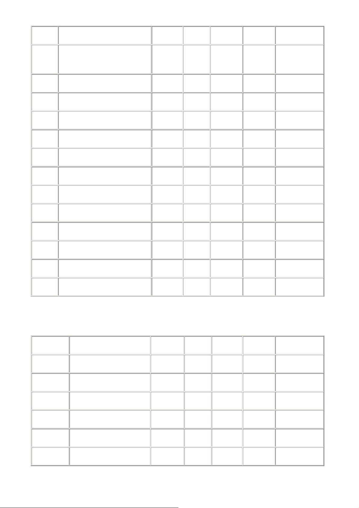
S11 DTMF Tone duration 50-255 0.001s * 100 D
S12 ReservedEscape (+) Prompt
Delay
S13 Echo 0-1 1 E
S14 Quiet 0-1 0 Q
S15 Verbose 0-1 1 V
S16 Pulse/ Tone 0-1 * 1 T,P,D
S17 Reserved
S18 Test Timer 0-255 s 0 &T
S19 System Inactivity Timer 0-255 min 0
S20 Reserved
0-255 0.02s * 50
S21 Break Length 0-9 100ms 0 \B
S22 Origin/Answer 0-1 0
S23 XOFF Character (NA) 0-127 ASCII 0
S24 Flash Timer 0-255 10 ms 50
Important Note: The following S-register List is only to be used by OEMs.
For end users, the contents of the first 24 S-registers should suffice.
S# Function Range Units PW Default AT Command
S25 Delay to DTR Off (NA) 0-255 0.01ms 0
S26 RTS to CTS delay (NA) 0-255 0.01ms 0
S27 Auto Answer clear timeout 0-255 s 8
S28 Pulse Set/Break Ratio 0-4 0 &P,P,D
S29 Speaker Control 0-3 1 M
S30 Speaker Volume 0-3 2 L
Page 50

S31 Automode Select 0-1 1 +MS
S33 Requested MIN Speed bps
Code
S34 Requested MAX Speed bps
Code
S35 Actual Speed after
CONNECT
(See Xn )
S36 Current Data Pump Status Mod
S37 Actual Modulation (DP) Mod
S38 Actual Rx Speed Bps
bps
Code
Code
Code
+MS
+MS
Code
S39 Line Quality Control 0-2 2 %E
S40 Reserved
S41 Received Signal Level 0
S42 SNR dB
S43 Result Codes control 0 X
S44 Reserved
S45 Transmit Gain Level 0-10 -dBM 250
S46-
S49
Reserved
S50-
S55
S56 Extended Code 0-4 4 X
Reserved for Test &T
Page 51

S57 Reserved
S58 Reserved
S59 Current Setting 0-5 0 Z, &F
S60 CD 0-1 1 &C
S61 RTS 0-1 0 &R
S62 Flow Control 0-3 1 &H
S63 DTR 0-3 0 &D
S64 DSR 0-1 0 &S
S65 Reserved
S66 Circuit 106 (RTS) 0-1 0
S67 Circuit 107 (DSR) 0-1 0
S68 Circuit 109 (CD) 0-1 0
S69
S70 CONNECT message
format
S71 CONNECT msg speed
source (DCE/DTE)
S72 Handset Record Gain 0 - 255 * 19
S73 Reserved 3
S74 Playback Volume 0-255 153 #VGT
S75 CID Enable 0,1 0 #CID
0-1 0 &A
0-1 0 &E
S76 ADPCM Bits Per Sample 4,8,16 4 #VBS
S77 Beep Tone Timer 0-40 1/10 s 10 #VBT
S78 Line Selection Duration 0,2,3,6 0 #VLS
S79 Ring Goes Away Timer 0-255 1/10 s 70 #VRA
Page 52

S80 Ring Never Came Timer 0-255 1/10 s 70 #VRN
S81 Silence Detect Enable 0,1 0 #VSD
S82 Silence Detect Sensitivity 0-3 2 #VSS
S83 Silence Detect Duration 0-255 1/10 s 55 #VSP
S84 Dtmf Tone Reports Cap0 0-3F 0 #VTD
S85 Dtmf Tone Reports Cap1 0-3F 0 #VTM
S86 DTMF Tone Reports Cap2 0-3F 0 #VTM
S87 Time Mark Placement 0-255 1/10 s 0 #VTM
S88 SPK <mute> 0-2 1 #SPK
S89 SPK <speaker> 0-15 5 #SPK
S90 SPK <mic> 0-3 1 #SPK
S91 Voice Sample Rate 1,2 1 1 #VSR
S92 Answer Delay 0-255 s * 2
S93-
S99
S100-S137 Reserved for V42 \A,\N, %C
S138 Mic Gain 0-255
S139 Line record Gain 0-255
S140-S142 Reserved
S143 Reserved for Test
Reserved for Diagnostics
S141-S143 Reserved
S143 Test auxiliary 0-1 0 %T
S144-
S145
Reserved
Page 53

S146 Pulse make Ratio 0-100 % * 36 &P
S147 Pulse PPS 10,20 pps * 10 &P
S148 Pulse Pause 0-255 10ms * 80
S149 Pulse Refresh 0-100 ms * 0
S150 FCLASS Value 0,1,8 0 +FCLASS
S151 FAE Value 0,1 0 +FAE
S152 Line Out Gain 0-255
S153 Spk Out Gain 0-255
S154 HSet Out Gain 0-255
S155-S160 Reserved
S161 Default Setting 0-1 2 Y
S162 Country Type 0-25 0
S163-S169 Reserved
S170-
S174
S175-
S179
S180-
S191
S192 Reserved
Debug Registers
Reserved
Reserved for Diagnostics
S193 Processor Type 0-100 0
S194-S196 Reserved 0
S197 HW Diag
S198 STRM Diag 0/1 0 *B
Page 54

S199 Port Diag 0/1 0 *B
S200 Blacklist Enable 0/1 * 0 *B
S201 Blacklist Dial Attempts 0-255 * 5 *B
S202 Min Time between calls 0-255 Sec * 120 *B
S203 Blacklist Time Out 0/1 * 5 *B
Page 55

Federal Communications Commission (FCC) Statement
15.21
You are cautioned that changes or modifications not expressly approved by the part
responsible for compliance could void the user’s authority to operate the equipment.
15.105(b)
This equipment has been tested and found to comply with the limits for a Class B
digital device, pursuant to part 15 of the FCC rules. These limits are designed to
provide reasonable protection against harmful interference in a residential installation.
This equipment generates, uses and can radiate radio frequency energy and, if not
installed and used in accordance with the instructions, may cause harmful interference
to radio communications. However, there is no guarantee that interference will not
occur in a particular installation. If this equipment does cause harmful interference to
radio or television reception, which can be determined by turning the equipment off
and on, the user is encouraged to try to correct the interference by one or more of the
following measures:
-Reorient or relocate the receiving antenna.
-Increase the separation between the equipment and receiver.
-Connect the equipment into an outlet on a circuit different from that to which the
receiver is connected.
-Consult the dealer or an experienced radio/TV technician for help.
You are cautioned that changes or modifications not expressly approved by the party
responsible for compliance could void your authority to operate the equipment.
FCC RF Radiation Exposure Statement:
This equipment complies with FCC radiation exposure limits set forth for an
uncontrolled environment. End users must follow the specific operating instructions
for satisfying RF exposure compliance. This transmitter must not be co-located or
operating in conjunction with any other antenna or transmitter.
Note :
The end product shall has the words “Contains Transmitter Module FCC
ID:SMW56AZBT”or”Contains FCC ID:SMW56AZBT” on the ID label
 Loading...