

Page 1

The 802.11g Wireless LAN Card
User’s Manual
User Instruction Manual for Windows 98 SE / ME / 2000 / XP
Page 2

Table of Contents
Chapter 1 Introduction ...................................................................................3
About This Manual ............................................................................................4
Product Overview..............................................................................................5
802.11g Wireless LAN Card Features...............................................................6
System Requirements.......................................................................................6
Installation Overview.........................................................................................6
Chapter 2 Wireless Network Concepts .........................................................8
Wireless LAN Network Modes...........................................................................9
Planning Your New Wireless Network.............................................................11
Chapter 3 Installation ...................................................................................15
Chapter 4 Configuration & Operation .........................................................18
Wireless LAN Configuration for Windows 98 SE / ME / 2000.........................18
The WLAN Management Utility (Windows 98 SE / ME / 2000) .......................19
Wireless LAN Configuration for Windows XP..................................................35
Chapter 5 Uninstall.......................................................................................51
Uninstall the WLAN Utility ...............................................................................51
Appendix A
Glossary..........................................................................................................53
Page 3
Chapter 1 Introduction
Congratulations on your decision to use wireless networking. The 802.11g
Wireless LAN Card is a high performance, IEEE Standard 802.11g
compatible, wireless networking card that installs into your PC’s slot to
support wireless LAN communications at speeds up to 54Mbps with other
PC’s located hundreds of feet apart.
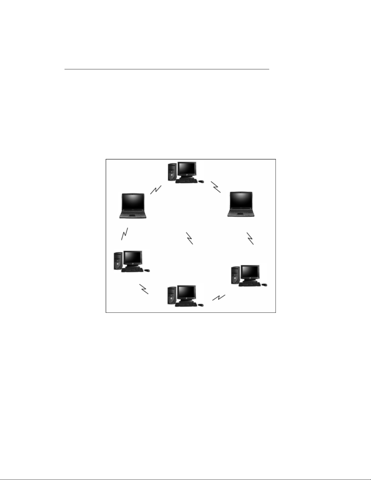
Figure 1 Typical Wireless LAN Network
The 802.11g Wireless LAN Card allows reliable, secure and untethered
access to your data providing you with exciting new ways to adapt to your
lifestyle and needs. Without the limitations of wires, true mobility and data
access is seamless in your office or home office.
3
Page 4

Data access from work, streaming audio MP3’s from a notebook to a stereo,
downloading Internet content wirelessly from a broadband connection,
watching TV on a notebook, are all possibilities with the 802.11g Wireless
LAN Card.
About This Manual
This manual provides you with all the information necessary to successfully
install and use your new 802.11g Wireless LAN Card. The manual is divided
into six chapters and two appendices as follows:
• Chapter 1- Introduction. This chapter provides a brief overview of the
802.11g Wireless LAN Card and the installation process.
• Chapter 2-Wireless Networking Concepts. This chapter introduces the
major terms and explains the various concepts associated with configuring
wireless LANs.
• Chapter 3-Installation. Provides hardware installation and software setup
procedures to prepare your PC for Wireless LAN Card operation. You will
also need to perform the LAN configuration procedures described in
Chapter 4.
• Chapter 4-Configuration & Operation. This chapter provides operating
instructions for the Wireless LAN Card and provides procedures for
configuring your wireless LAN after completion of installation and initial
setup.
• Chapter 5-Uninstalltion. This chapter details how to uninstall the WLAN
Management Utility.
4
Page 5

• Appendix A-Glossary. Defines various terminology associated with Wireless
LANs.
Product Overview
The 802.11g Wireless LAN Card gives you the freedom of secure high-speed
communications with other PCs without the need for interconnecting wires.
You can even connect in to other LAN infrastructures such as your company’s
internal Ethernet LAN or your own home network. The antenna and design of
the Wireless LAN Card gives you unmatched sensitivity which means your
system will remain connected to other wireless PCs at high speeds for longer
distances.
The Wireless LAN Card operates according to the IEEE 802.11g Wireless
LAN specification, for wireless data communications at speeds up to 54Mbps
(Megabits per second). IEEE 802.11g operates on frequencies in the 2.4GHz
range using OFDM (Orthogonal Frequency Division Multiplexing) technology.
Backed by international standards and the IEEE organization, IT departments
and end-users alike benefit from the reliability and interoperability of products
based on these standards. From an investment point of view, it makes good
business sense investing in technology that will be support worldwide for
many years to come (unlike technologies not backed by international
communications standards). Whether you are running a company or a home
office, the Wireless LAN Card reduces, or eliminates in some cases, the need
to setup wired LAN networks in the office or home office, eliminating costs
associated with wiring rooms and buildings.
5
Page 6

802.11g Wireless LAN Card Features
• Up to 54Mbps data transfer rates for high-speed access to data
• Compatible with 802.11g Wi-Fi CERTIFIED equipment (2.4GHz operating
range)
• Plug-and-play with Microsoft Windows operating systems
• Secure data access, up to 128-bit WEP encryption protection
• Driver requires minimal memory footprint and CPU support
• Easy upgrades via software driver, no firmware to upgrade
• Provides seamless connectivity to Wireless and hardwired LANs
System Requirements
• PC with Windows 98 SE, Windows 2000, Windows ME, or Windows XP
Operating Systems
• One (1) available Slot
• CD-ROM drive (for the drivers and configuration software)
Installation Overview
The installation process is relatively fast and simple.
1. Place the CD-ROM supplied with your 802.11g Wireless LAN Card
(containing the drivers and configuration software) in your CD-ROM
drive and the configuration software auto starts. Simply go through a
series of self-prompting screens and select from the options to
6
Page 7

configure your Wireless LAN Card for your particular operating system
(these procedures are detailed in Chapter 3-Installation).
2. Plug the Wireless LAN Card into your PC’s Slot.
3. Set up your wireless LAN using the instructions in Chapter 4. Record
your security codes (WEP keys), etc. for later reference. Repeat steps
1 through 3 for each PC that will be connected to your wireless LAN.
Your wireless LAN should now be fully functional.
4. If you are experiencing problems after completion of the installation
procedures, refer to Chapter 6, Troubleshooting.
7
Page 8

Chapter 2 Wireless Network
Concepts
For the past few decades, wired Local Area Networks (LAN) or more
commonly know as Ethernet, have provided a seamless way of connecting
and communicating with multiple PCs, desktops, laptop/notebooks, servers
as well as a host of other peripherals, including printers, scanners, etc. LANs
have served us well in environments where users were not mobile or had little
need to access data other than in their office.
With the advent of notebook computers and an increasingly mobile computing
society, the need for wireless networking finds more applications with each
passing day. Wireless LANs have evolved to meet the needs of mobile
computing and are becoming very popular as compatibility, reliability and
familiarity increases and equipment costs decrease.
Wireless LANs (WLAN) allow users to roam freely about a network taking
their computers with them while still maintaining a networking connection. In
essence, WLANs are an extension of wired LAN networks, where the critical
need is data access and mobility. The tradeoffs are slower speeds (although
quite satisfactory for Internet and email access) and limited roaming distance,
as dictated by the environment.
A basic WLAN network requires client nodes and access points, similar to a
LAN with its clients and infrastructure (switches, repeaters, etc.). The access
point is the connection to the wired LAN network or a designated computer
device performing the supervisory function, while client nodes are typically
WLAN adapters installed in peripheral computing devices, such as notebooks,
desktops, personal digital assistants (PDAs) and others. Once a WLAN is
8
Page 9

setup, it acts like a wired LAN, using the same protocols designated for
communicating via the IEEE Ethernet standard.
Wireless LAN Network Modes
WLANs basically have two modes of operation:
• Ad-Hoc mode
• Infrastructure mode
What is Ad-Hoc mode?
An Ad-Hoc WLAN is created when two or more PCs equipped with Wireless
LAN Cards (WLAN clients) are configured to use the same radio channel and
Network Name in the same area and can communicate freely with each other,
without the need for an Access Point to a hard-wired LAN network. Only PCs
that use the same radio channel and network name can communicate over
the Ad-Hoc network. This type of a network is a peer-to-peer relationship
where each computer talks directly to one another with no one PC being
dominant.
9
Page 10
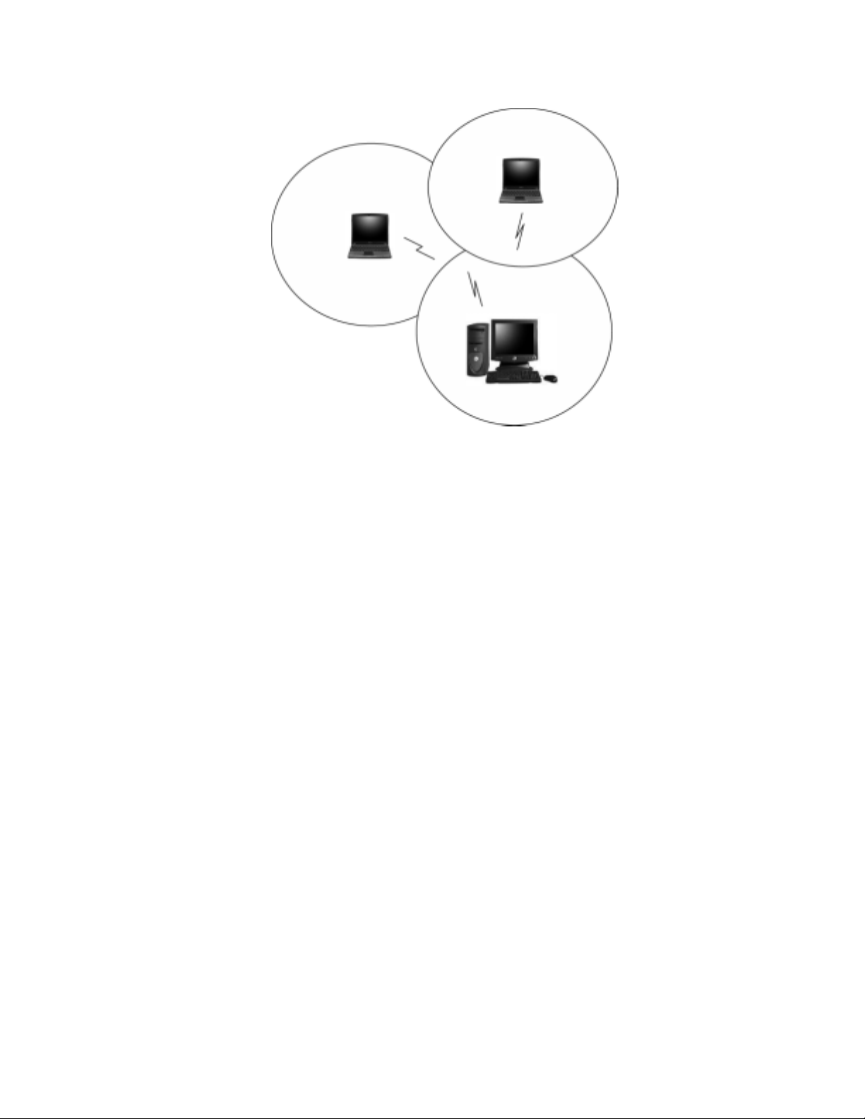
Figure 2 Ad-Hoc Mode: Two or More PCs with 802.11g Wireless LAN
Cards
Configured to Same Radio Channel and Network Name
Infrastructure Mode
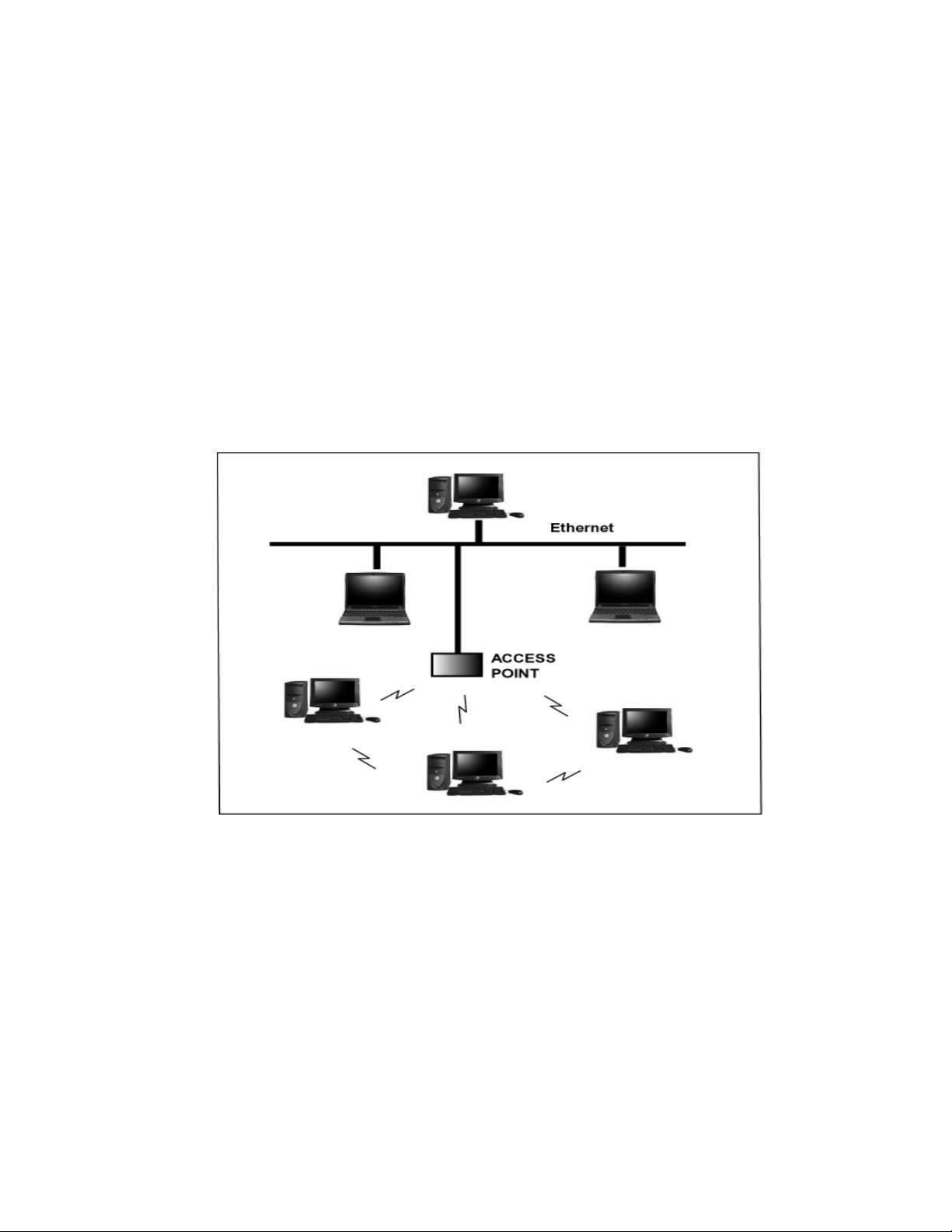
When a WLAN access point is introduced into the WLAN, the access point
and its clients (each PC) comprise a Basic Service Set (BSS), whereby the
access point serves as the connection to the wired LAN for each client.
Clients within the same BSS do not directly communicate between each other;
rather they communicate to the AP that routes the data to the appropriate
destination.
The access point bridges both wired and wireless networks, allowing wired
and wireless client communication. This arrangement of WLAN access points
and clients is commonly referred to as Infrastructure mode. An access point
also extends the range of the WLAN, double over that of client only networks
because the access point is able to forward data within its BSS.
10
Page 11
Infrastructure mode enables the network clients to freely roam, once an ESS
(Extended Service Set) is established.
With all clients using the same radio channel and ESS ID (sometimes referred
to as SSID which is a given name to the network), users are fully mobile
within the range of the access point signal. Access points should be situated
in location to deliver the largest range of signals, with minimal interference.
Best performance and signal quality is often affected by building structures,
walls, etc., and may require some trial-and-error to identify the best location
for access points.
Figure 3 Infrastructure Mode-Combination Wireless and Hardwired
LANs
Planning Your New Wireless Network
First, determine what components (WLAN cards, access points) and what
kind of network will be created (Ad-Hoc, Infrastructure mode). Then select
your network name (SSID), WEP key (security password) and channel
11
Page 12

number (1 through 11 in US, 1 through 13 in Europe and 1 through 14 in
Japan). All members of the wireless LAN will have to configure their PCs to
the same SSID, WEP and Channel number to talk to each other. SSID, WEP
key and channel number are essential to understanding and creating a
successful wireless network.
These concepts are explained in the following paragraphs.
What is SSID?
A wireless network requires a BSS or ESS to operate and a name associated
with it. SSID literally stands for a network name for use with that Service Set
of clients and access points if so set up. All computers must have the same
SSID as the network in order to communicate over the new network. The
SSID name can be any name such as “wireless_lan”, “Bob’s domain”, or
“AbCdE123”, and can include numbers as well as be case-sensitive. If the
exact SSID name is not used, then that wireless client cannot logon into that
network.
What Channel Do I Use?
IEEE 802.11g wireless LAN networks communicate using one of several
available channels (each with a different operating frequency) to reduce the
interference from other potential sources or users of that channel. Depending
on the country where the network is being set up, you may have a choice of
up to 14 channels available. In the US, channels 1 through 11 are defined for
use in the 2.4GHz spectrum used by 802.11g. In Europe, channels 12 and 13
are added, while Japan can have up to 14 channels. Channels 1, 6 and 11
are the most commonly used channels in the US.
12
Page 13

For your network, choose a channel that offers little interference and
configure all users of this network to the same channel.
What is a WEP key?
WEP provides for two levels of security encryption based on the length of bits
in a key called a Shared Key. A 40-bit key (which is 5 characters) provides
some security; this can be a key like “12345” or “MyLAN”. A 104-bit key is
also available and provides more robust security. A 13-character key is
required for 104-bit security. Keys can be in ASCII characters or Hexadecimal.
ASCII characters are those used in computers and include all typewritten
characters including the alphabet and numbers, as well as */”()[] characters.
Hexadecimal characters are limited to the numbers 0-9 and the first 6 letters
of the alphabet a-f.
Table 1 WEP Key Examples
WEP Key size Number of Digits Example
5 (ASCII) 12345, MyLAN, 78E*5
40-bit (also called 64-bit)
10 (Hexadecimal) 1A37FB458C
13 (ASCII) 1234567890123,This_is_MyLAN
104-bit (also called 128-bit)
26 (Hexadecimal) 1A37FB458C12E34F8523E9FF76
Note: Every key has an added 24-bit provided by the card, which are set by
the manufacturer and not user modifiable. This manual uses the terms
40-bit and 104-bit to represent 64-bit and 128-bit keys respectively. This
is the most commonly used terminology in the industry.
13
Page 14

The WEP key for your wireless LAN network is another form of password.
Like passwords, certain combinations of passwords are not recommended for
use (such as 01234, abcde, or publicly known information like your office
phone number, dog’s name, etc.). Protect your WEP key as you would a
password.
Note: If you access other networks with already predefined keys, always
enter them exactly as they appear taking note of lower and upper case letters.
Any computer accessing a wireless network with WEP enabled not only
requires the same SSID but also the same WEP key in order to have access.
With the above factors decided, physical placement of the components will be
critical. The maximum range of the wireless LAN will often be decided by the
type of environment it is located in and, if in different rooms, by how many
obstacles are in the way which reduces the range of the wireless adapters.
Often, Ad-Hoc mode will require the wireless clients to be in closer range of
each other than Infrastructure type networks. The Wireless LAN Card can
operate at up to 100m indoors and up to 300m outdoors, although the
physical environment (walls, floors, ceilings, etc.) will limit the range of
wireless signals.
14
Page 15
Chapter 3 Installation
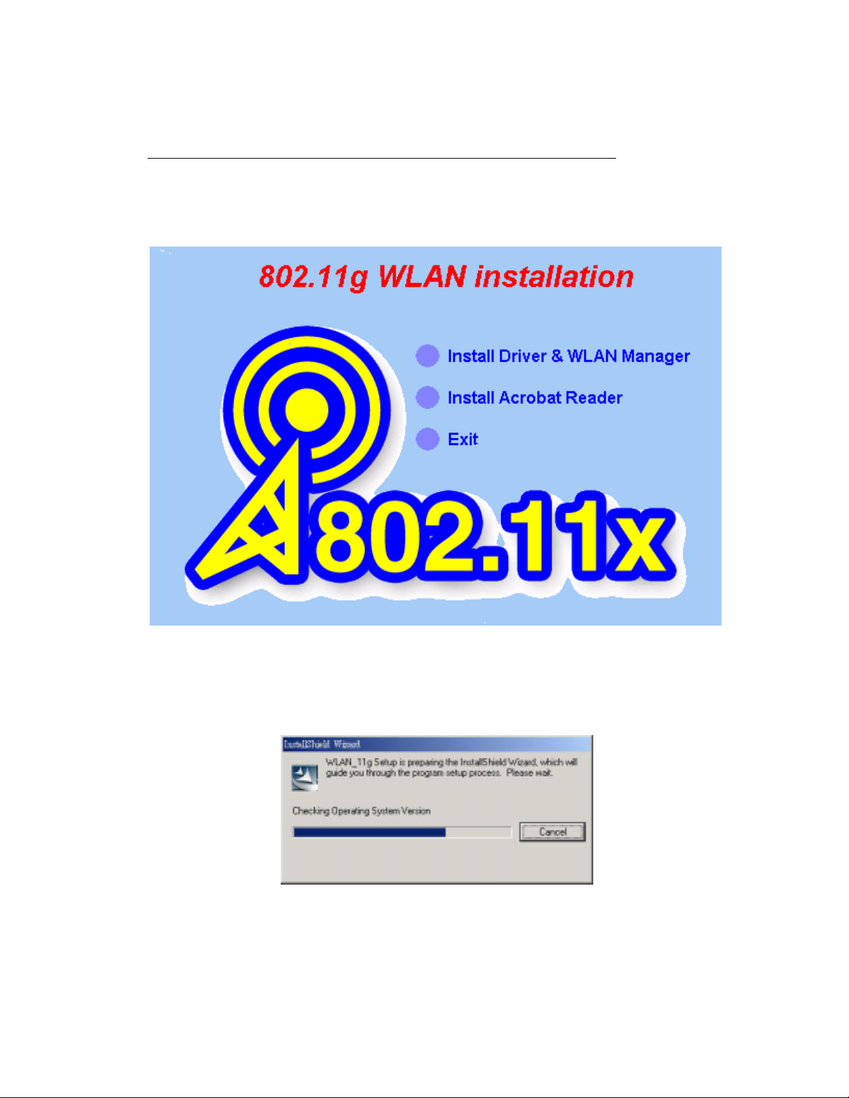
1. Insert the installation CD into your CD-ROM drive. The setup program will
start automatically.
15
Page 16
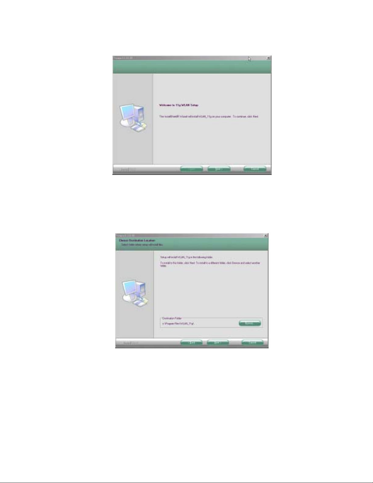
2. Click Next to begin the setup.
3. Select the destination folder. To install to the default folder as shown below,
click Next to continue.
4. The necessary Driver and Utility files will be copied to your system
directory.
16
Page 17
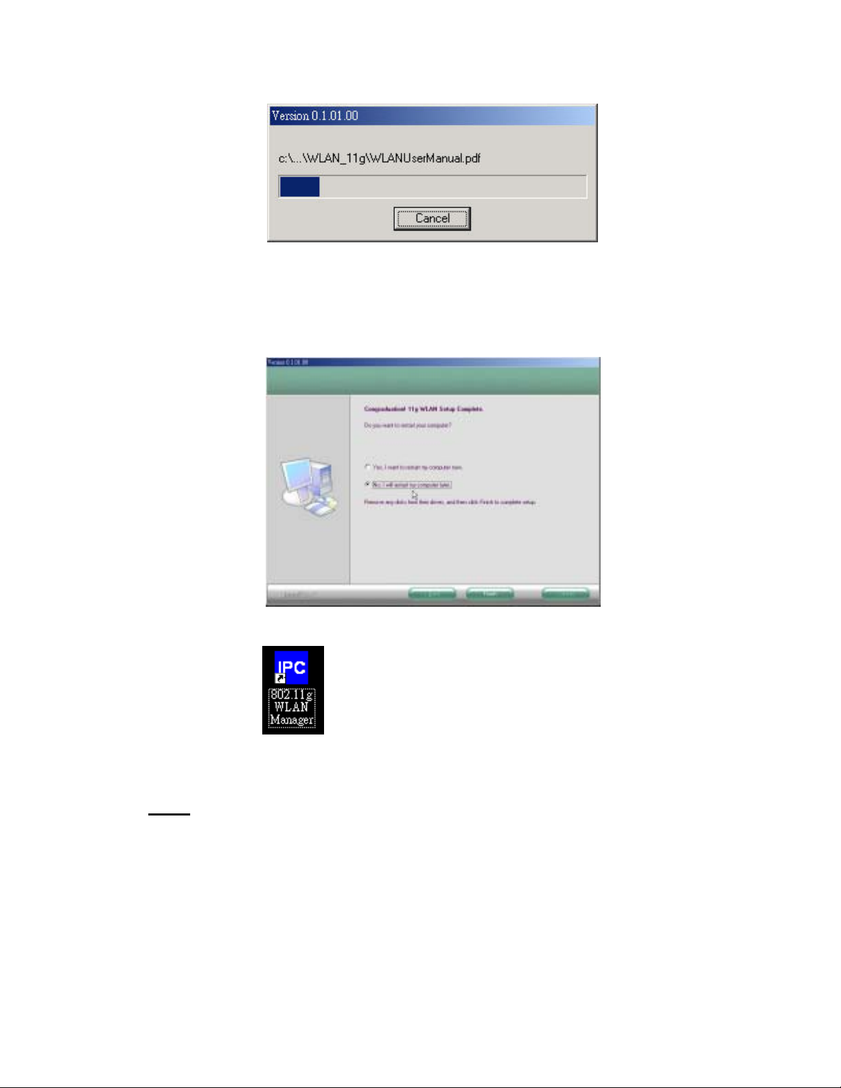
5. Select No and then click Finish to complete the installation (Windows 98
SE and ME users must select Yes).
6. The shortcut will appear on your desktop. By click this icon, you
can run the Utility program.
Note:
After installing a new network adapter, Windows automatically
configures the TCP/IP protocol to automatically obtain an IP address
from a DHCP server. Depending on your setup, you may want to
consider specifying a fixed IP address for your new wireless adapter.
17
Page 18

Chapter 4 Configuration &
Operation
Once the driver is installed, the 802.11g Wireless LAN Card will be up and
running. If you encounter any difficulties, consult Chapter 6, Troubleshooting.
This chapter provides general operation and configuration information for use
after initial installation is completed.
Configuration of the Wireless LAN Card is dependent on the operating system.
Please follow the instructions carefully to make sure you are taking the
appropriate steps for your operating system.
Wireless LAN Configuration for Windows 98 SE
/ ME / 2000
If your PC uses Windows 98 SE, Windows ME, or Windows 2000, use the
following configuration procedure.
NOTE: If your PC uses Windows XP, skip this procedure and refer to the
paragraph titled, “Wireless LAN Configuration for Windows XP” located
further in this chapter.
Utility Startup Configuration Details
The Wireless LAN Card has its own management software. Users can control
all functions provided by the application named WLAN Utility. You may run
the utility by double clicking the WLAN Utility shortcut on your desktop.
18
Page 19

Three colors are used to describe the status of the connection icon shown in
the System Tray. Green indicates excellent connection. Yellow indicates the
connection has poor quality, and Red means no connection. Double click the
icon and the WLAN utility will be opened.
The WLAN Management Utility (Windows 98 SE
/ ME / 2000)
The WLAN Utility contains the following four major functions. Each function is
described in detail below:
• Status: provide the information of the current wireless connection.
• Profile: allow users easily configure different settings for each profile.
• Survey: support site-survey tool to list the active access points that are
within the range of your computer.
• About: provide valuable information about the firmware and software
version,
MAC address, and so on.
Status Tab
The Status tab provides information on the current profile, if any, being used
in the wireless connection. The information listed on the Status tab is
indicated below. Figure 1 shows the screen layout of the Status tab:
19
Page 20
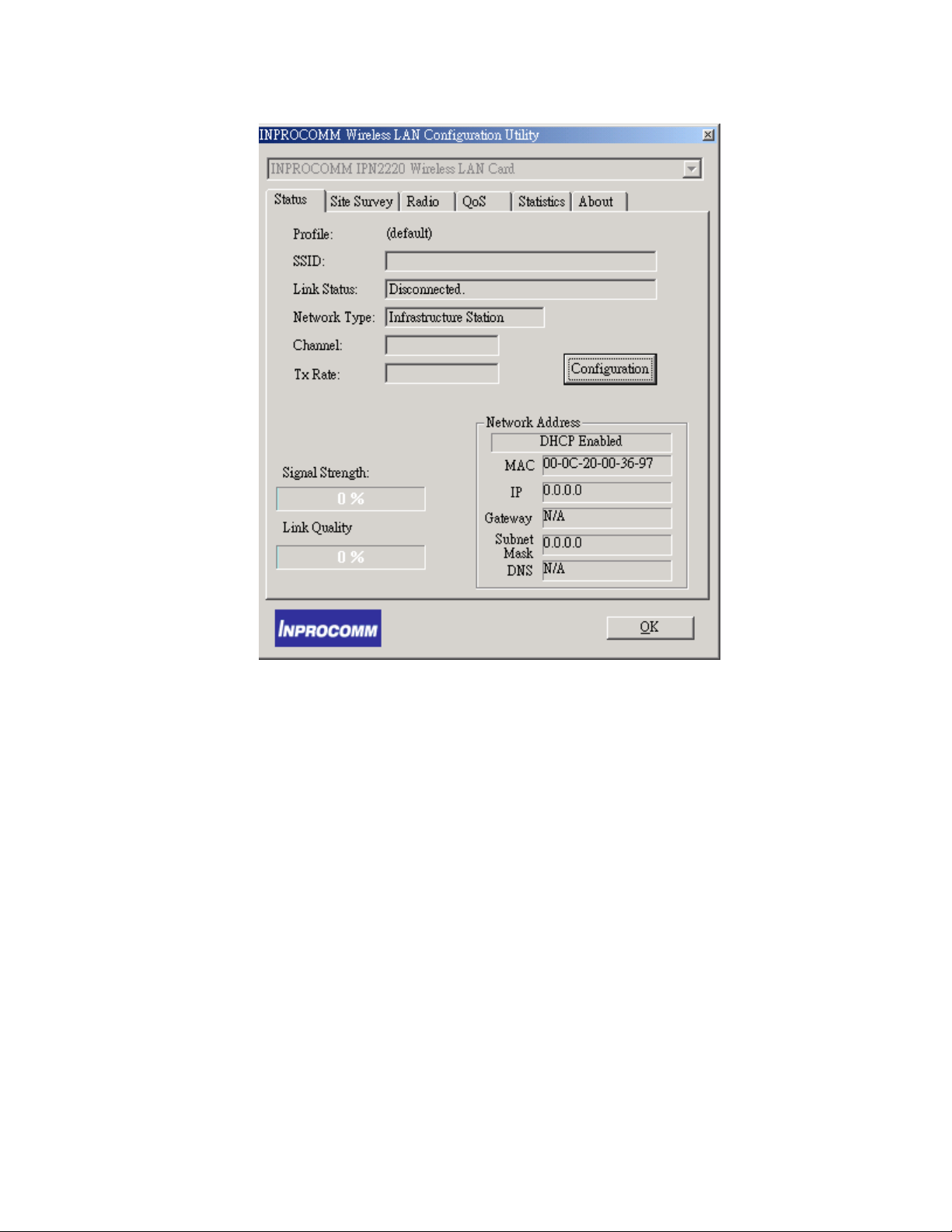
Profile Name
The name of profile currently in use
SSID
The name of the SSID (Service Set Identification) associated with the profile.
Link Status
This field is used to display the current state of the driver. The LINK Status
field can be the following: Check this box to have networks automatically
connection when available
20
Page 21

Associated - Normal flow of operation between stations in Ad-Hoc mode
and
Infrastructure mode.
Not Associated - means the node cannot detect any Ad-Hoc station or
access point within the range.
Scanning - Searching for available access point or active node
Network Type
The mode can be either access point or peer-to-peer.
Access Point (Infrastructure Mode) – This mode of operation requires the
presence of an access point. All communication is done via the access point,
which relays packets to other wireless clients in the BSS as well as to nodes
on a wired network such as Ethernet.
Peer-to-Peer (Ad-Hoc Mode) – This is the peer-to-peer mode of operation.
All communication is done from client to client without the use of an access
point.
Channel
It shows what channel is used now.
Tx Rate
It shows the transmit rate being currently used for an active connection. The
value is masked when the state shows the “scanning” message.
21
Page 22
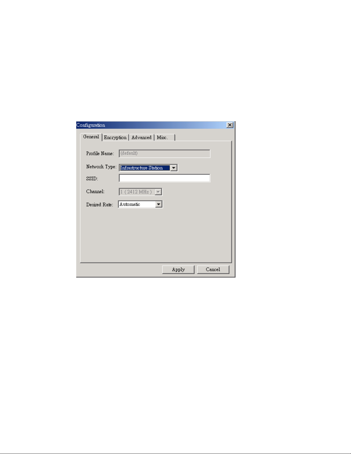
Configuration
This is used to configure the various profiles available to you for wireless connections.
The Profile tab contains some of the same fields as the Status tab, but unlike the
Status tab, all of the fields in the Profile tab are alterable. Figure 2 shows the screen
layout of the profile tab.
General
Profile Name
Allow to give a name to the profile. Any user can add 9 different profiles
at most if he wishes. After assigning a new profile name and complete
related fields shown below it, you then can press Apply to save the
profile. Click “Apply” or “OK” to activate the options that you have set.
22
Page 23

SSID
The identification of BSS (Basic Service Set) is associated with the
current profile. The default value is “ANY”. This allows your wireless
client to automatically associate to any access point in the vicinity of your
wireless client.
TIP: SSID is the name of the Wireless LAN network to
connect to. If some are detected, these will be displayed
on screen. Otherwise, enter a name to use. SSID is casesensitive. Always use the same spelling and case when
adding computers to the network.
NOTE: Record your SSID below and refer to it when necessary.
SSID name: __________________________________________
Network Type
This field allows you to select from a list of supported network mode. The
modes displayed will have “Access Point” and “Peer-to-Peer”. The
default value is “Access Point”.
Transmission Rate
23
Page 24

The transmission rate is the rate at which the data packets are
transmitted by the client. The default value is “54Mb” and cannot change.
Channel
Changing the channel is only effective in Ad-Hoc networks. Networking
operating infrastructure mode can automatically scans for a channel. Be
aware that when the peer-to-peer mode is selected, be sure to set your
wireless stations with the same channel.
Encryption
The Encryption button is used to equip an additional measure of security
on your wireless network, which can be achieved by using WEP (Wired
Equivalent Privacy) encryption. To prevent unauthorized wireless stations
from accessing data transmitted over the network, WEP can support high
secure data encryption. WEP encrypts each frame transmitted through the
radio by using one of the Keys entered from this panel. When an
encrypted frame is received, it will only be accepted if it decrypts correctly.
This will only happen if the receiver has the same WEP Key used by the
transmitter. The Encryption tab contains some fields as below.
24
Page 25
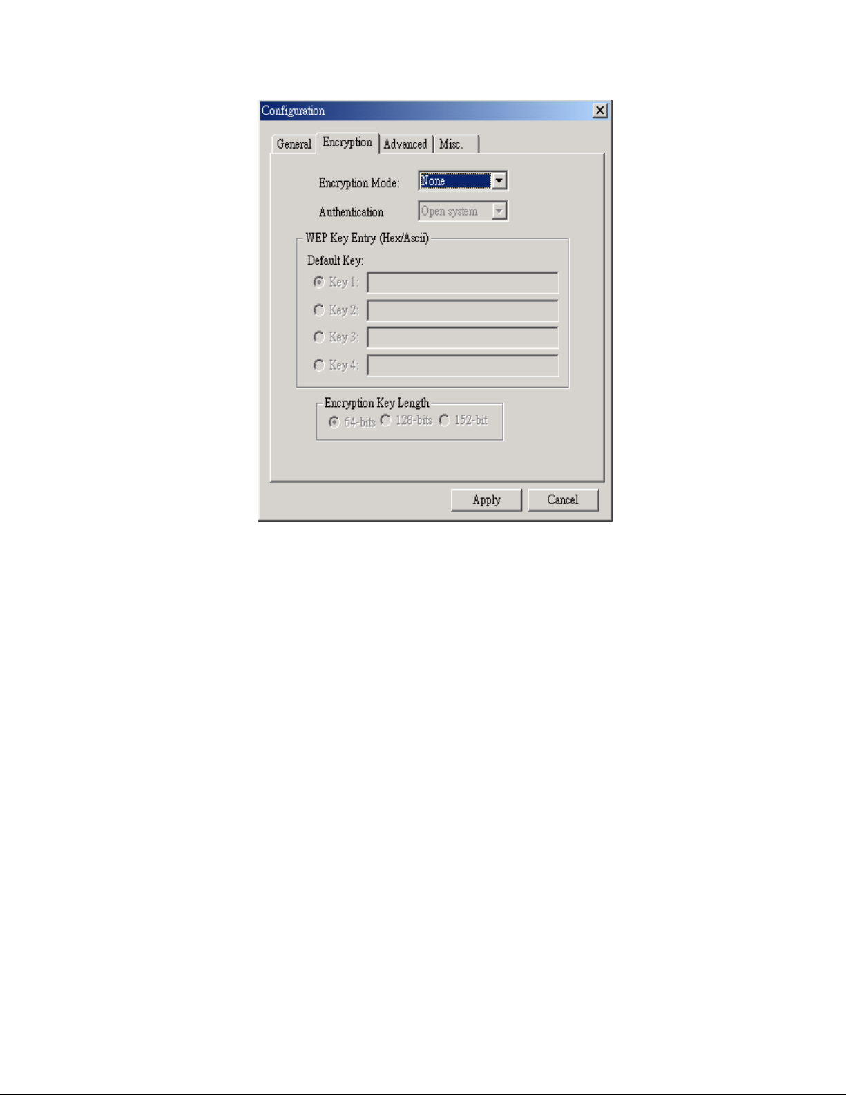
Encryption [WEP security]
The field allows you to select Disabling, 64-bit and 128-bit. When setting
64bit, or 128 bits, it means WEP security is used.
WEP Key
For 64-bit encryption:
• Alphanumeric: 5 characters (case sensitive) ranging from “a-z”, ”A-Z” and
“0-9”. (e.g. My*#Key)
• Hexadecimal: 10 hexadecimal digits in the range of “a-f”, "A-F" and "0-9".
(e.g. 11AA22BB33).
25
Page 26

For 128-bit encryption:
• Alphanumeric: 13 characters (case sensitive) ranging from “a-z”, ”A-Z” and
“0-9”. (e.g.MyKey12345678).
• Hexadecimal: 26 hexadecimal digits in the range of “a-f”, "A-F" and "0-9".
(e.g.00112233445566778899AABBCC)
TIP: WEP is a protocol defined in 802.11i to provide encryption
capabilities for wireless LAN communications. Because data travels
through air, there is a likelihood of unintended receivers listening in on
your data conversation. WEP encryption keys can be 64-bit (minimal
security) or 128-bit (more secure). Additionally a WEP key is needed to
encrypt and decrypt data packets, and any computer on a WEP network
must have the same key, otherwise it will not be allowed on that
It is recommended that you select WEP encryption to reduce security
risks and unauthorized users from using the wireless LAN network and
access to important data.
network.
Create Keys with Pass-phrase
WEP keys may be created using a Pass-phrase to randomly generate
the four keys. This saves considerable time when entering all four keys
into each node on the wireless network.
Key1, Key2, Key3, Key4
These four fields hold the manually entered keys. They will also display
the generated keys using a Pass-phrase.
26
Page 27
Ensure that the WEP key entered here matches all other applications and
clients using the same network. WEP keys can be case-sensitive, and
incorrect keys will not allow clients access to this network.
Note: Record your WEP key size and WEP key in the spaces below for
later reference.
WEP key size: ______________________________________
WEP key: __________________________________________
Use WEP key
This field updates the driver with the four keys displayed in Key1 through
Key4. These keys are also written to the registry for permanent storage.
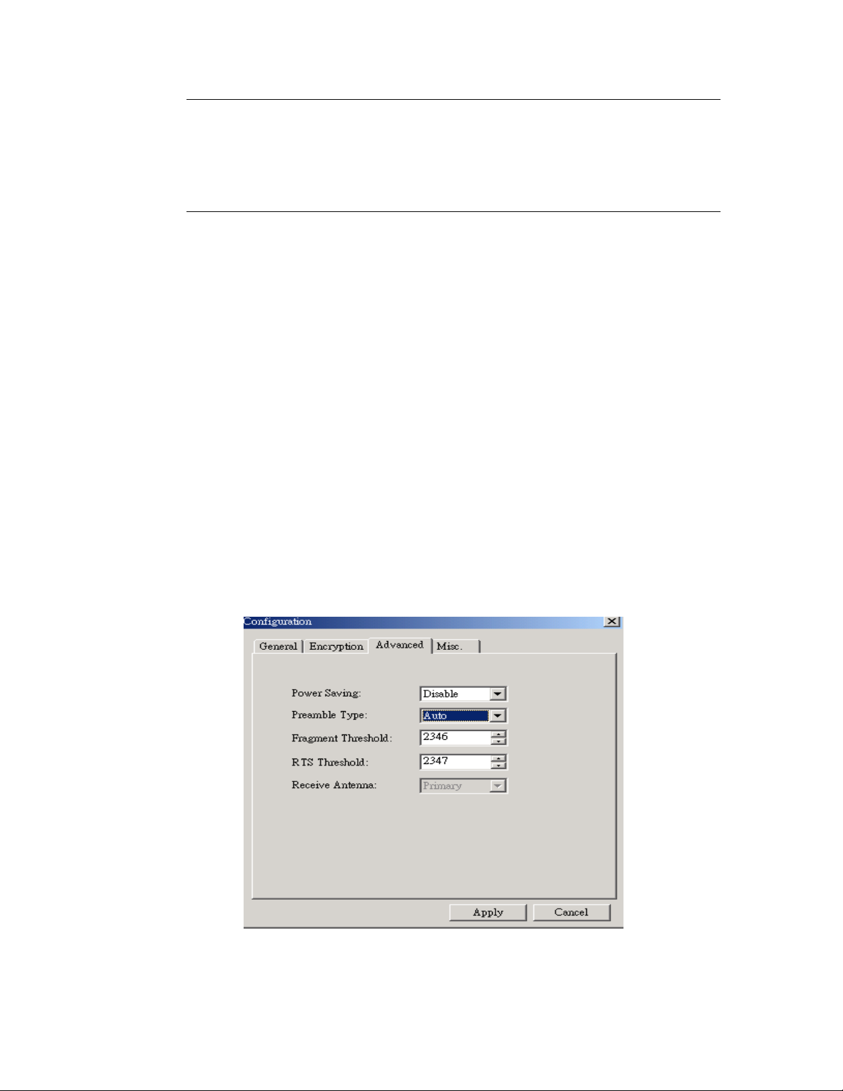
Advanced Button
27
Page 28

RTS Threshold
The field allows you to set enable or disable. When the field is set to
Enabled, you can adjust the value between 0 to 2432. RTS threshold is
a mechanism implemented to prevent the “Hidden Node” problem.
“Hidden Node” is a situation in which two stations are within range of the
same access point, but are not within range of each other. Thus, it
provides a solution to prevent data collisions. Enabling RTS Threshold
may cause redundant network overhead that could negatively affect the
throughput performance.
Fragment Threshold
The field allows you to set enable or disable. When the field is set to
Enabled, you can adjust the value from 256 to 2346. Fragmentation
mechanism is used for improving the efficiency when high traffic flows
along in the wireless network. If your wireless devices often transmit
large files in wireless network, you can enable the Fragmentation
Threshold and the mechanism will split the packet to send.
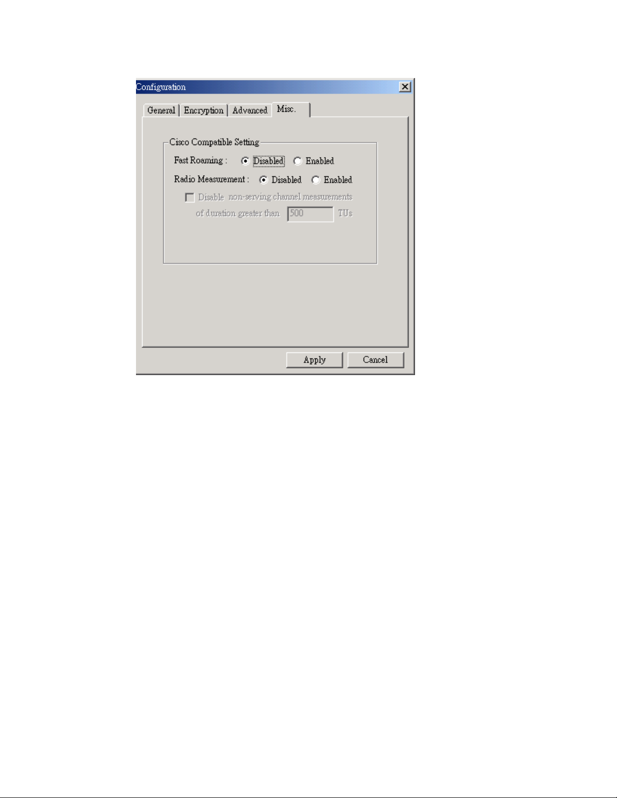
Misc. Button
For Cisco AP extension Function used. Linking to Cisco AP, you might
need to set fast Roaming or Radio measurement items.
28
Page 29
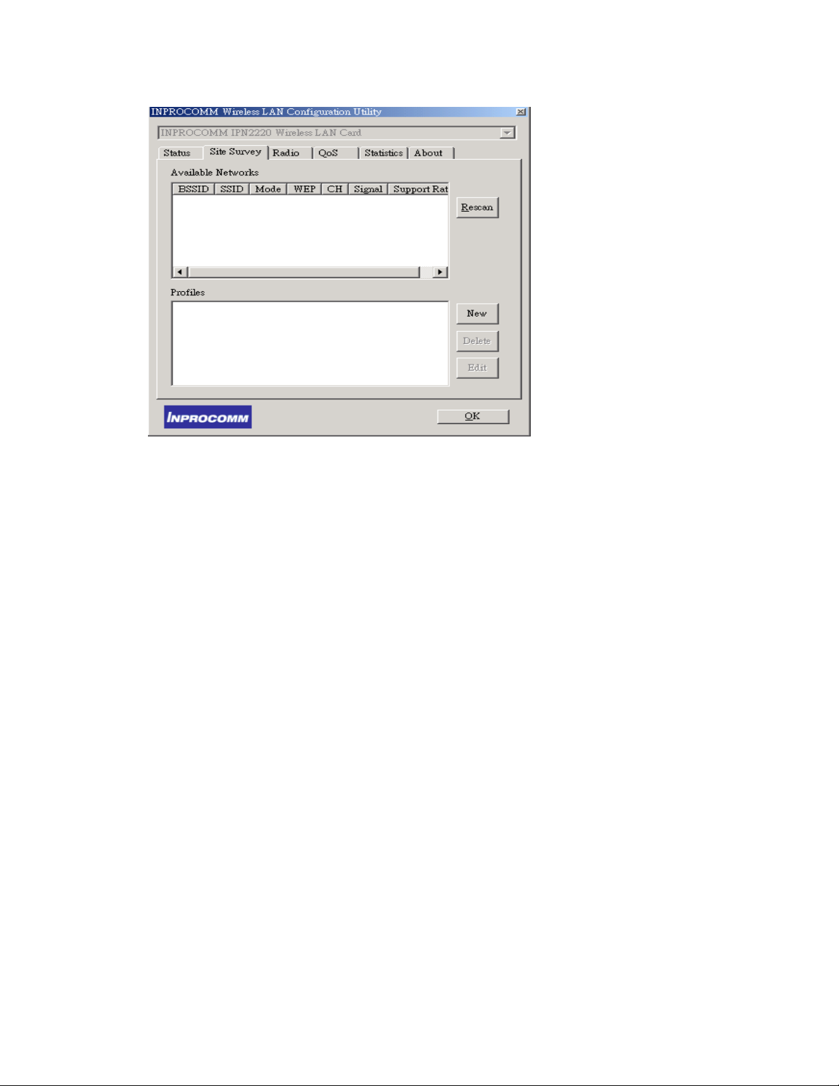
Site Survey Tab
The Survey tab supports powerful Site-Survey tool to discovery all active
wireless devices in the radio range. While selecting this wireless device
displayed on the screen, users can double click to quick connect the wireless
device chosen by users and simultaneously modify the Default profile
automatically. If users want to update the survey result, they can press
Rescan button again. Each row of the information contains the following
columns:
29
Page 30
Number of Discoveries
The total number of wireless LAN devices discovered by this Site-Survey.
SSID
The ESS ID stands for Extended Service Set Identification, and it presents
the SSID of the access point. In the peer-to-peer device discovered, all clients
should share the same SSID for communication.
BSSID
The BSSID stands for Basic Service Set Identification. During infrastructure
mode, it represents the MAC address of the access point.
30
Page 31

Mode
The discovered device is an access point (AP) or a peer-to-peer (P2P) device.
WEP
The discoverable device is encryption enable or disable in this column.
Signal Level
The signal measurement for each discovered device within the radio range. A
higher percentage means that this discovered device has stronger signal
strength. If the device you want to connect to has lower signal level, you can
move it closer to this device or vice versa.
Channel
This field shows the current channel used by the discovered device.
Radio Tab
Setting Radio ON/OFF and setting regulatory Domain Information
31
Page 32
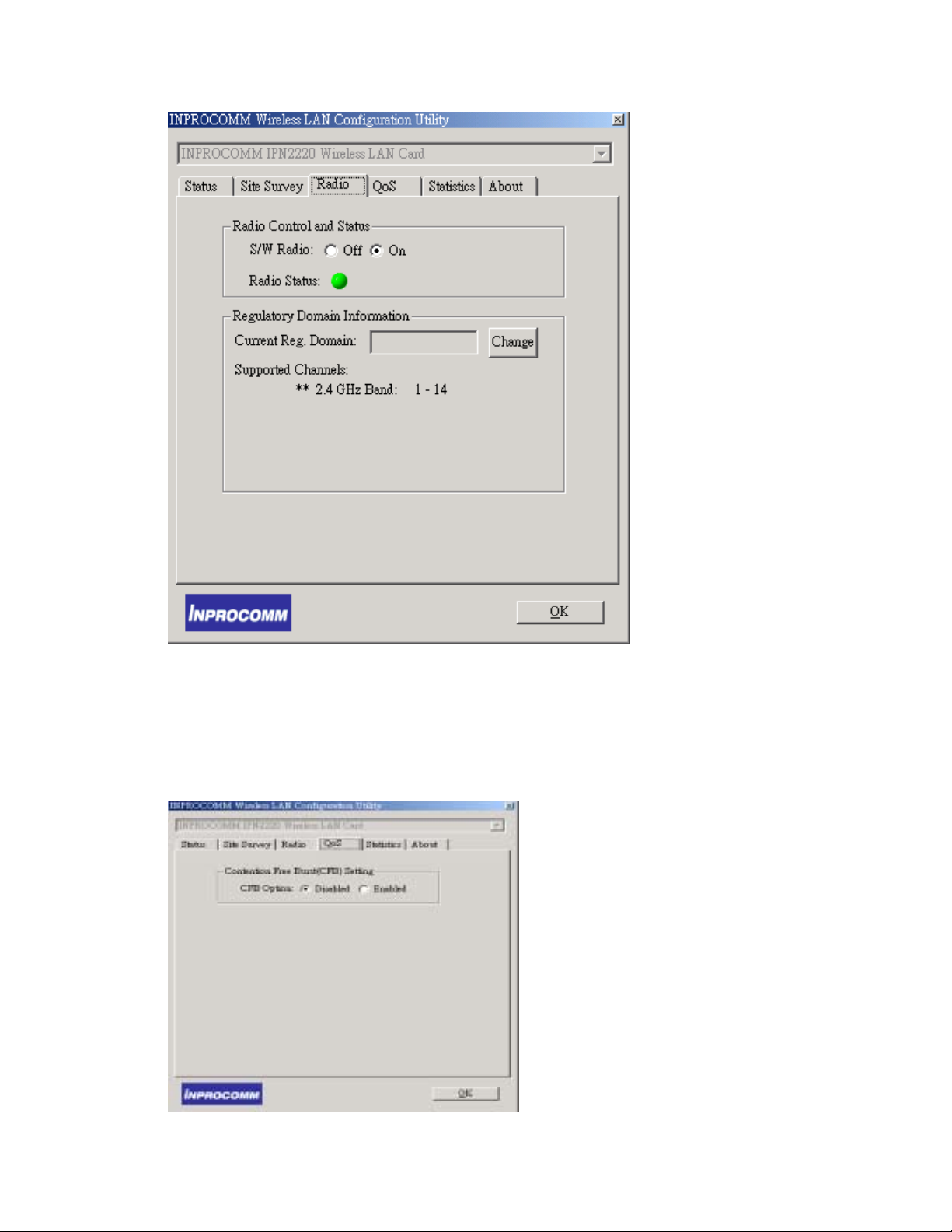
QoS Tab
Disable or Enable Contention Free Burst (CFB) Setting
32
Page 33
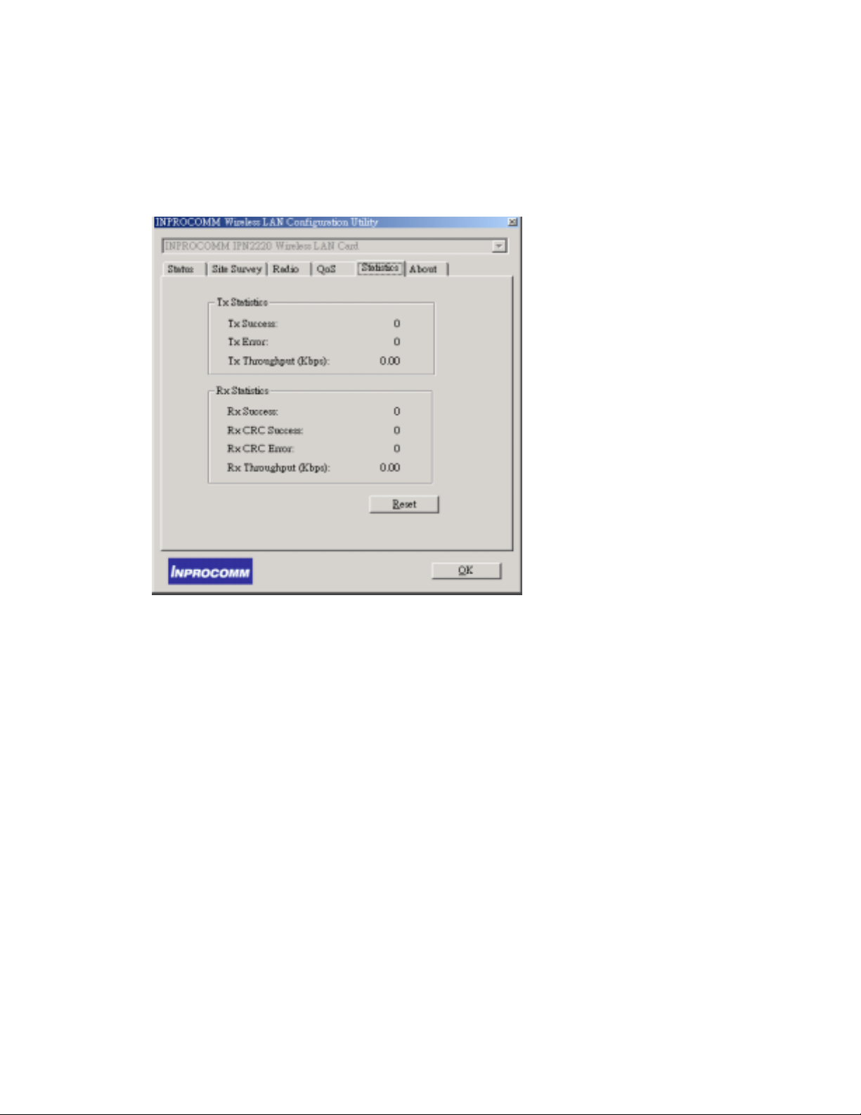
Statistic Tab
Shows situation of TX and RX packets.
About Tab
The About tab is used to show Wireless Client Management Utility version,
Serial Number and MAC Address of this Network Interface Card, Network
Interface Card Driver version and Network Interface Card firmware version.
Users need to use these version numbers when reporting their problems to
technique support.
33
Page 34
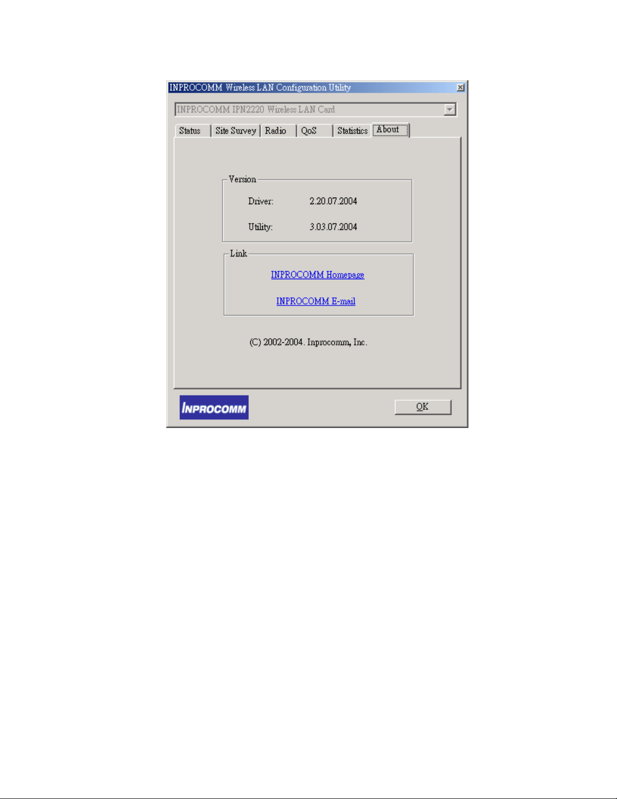
Driver Version
Device Driver version and date
Link
INPROCOMM Homepage
INPROCOMM E-mail
34
Page 35
Wireless LAN Configuration for Windows XP
Use the following procedure if you are configuring a Wireless LAN Card
Wireless LAN Card using a PC running the Windows XP operating system.
To configure your card for use with a network:
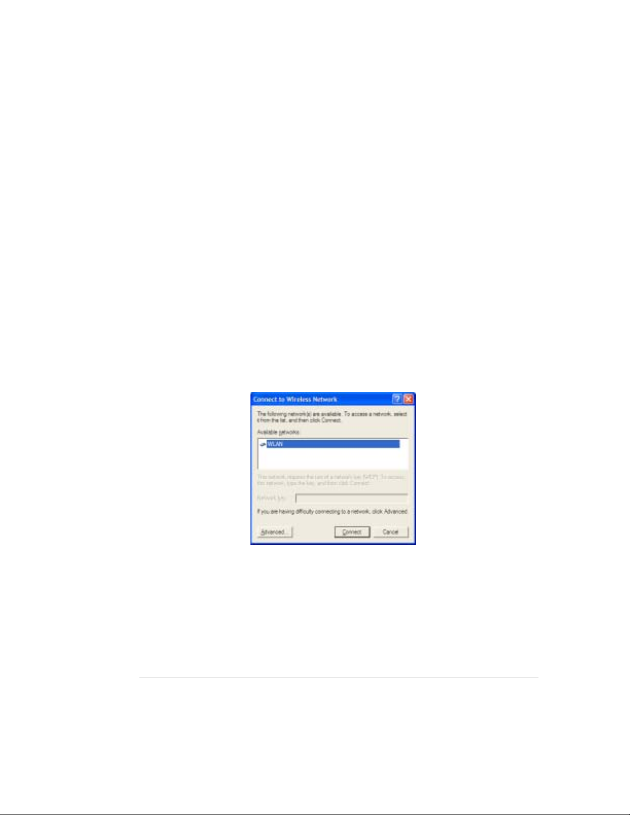
1. Left-click on the Wireless Network Connection indicator icon in the
System tray (lower right hand area) to launch the Connect to
Wireless Network window.
2. A list of available network SSIDs will be provided, if any are detected
or available. If a network is chosen and requires a WEP key, the key
should be entered in the Network Key field.
TIP: SSID is the name of the Wireless LAN network to
connect to. If some are detected, these will be displayed
35
Page 36

on screen. Otherwise, enter a name to use. The SSID is
case-sensitive. Always use the same spelling and case
when adding computers to the network.
NOTE: Record your SSID below and refer to it when necessary.
SSID name: __________________________________________
What is WEP? WEP is a security protocol defined in
802.11i to provide encryption capabilities for wireless
LAN communications. WEP encryption keys can be 40-bit
(minimal security) or 104-bit (more secure). Additionally a
WEP key is needed to encrypt and decrypt data packets,
and any computer on a WEP network must have the same
key, otherwise it will not be allowed on that network. It is
recommended that you select WEP encryption to reduce
security risks and unauthorized users from using the
wireless LAN network and access to important data. A 40bit key is 5 characters (such as “AbCdE”) while a 104-bit
key is 13 characters in length. Keys can be entered in
ASCII or Hexadecimal (see above “What is WEP” for
explanation).
Note:
Record your WEP key size and WEP key in the spaces below for later
reference.
36
Page 37
WEP key size: ______________________________________
WEP key: __________________________________________
3. Click Connect – This will attempt to connect the Wireless LAN Card
Wireless LAN Card to the selected network.
Difficulties Connecting to the Network
1. If you are having difficulty connecting, click Advanced to open the
Wireless LAN Card Wireless LAN Card Properties.
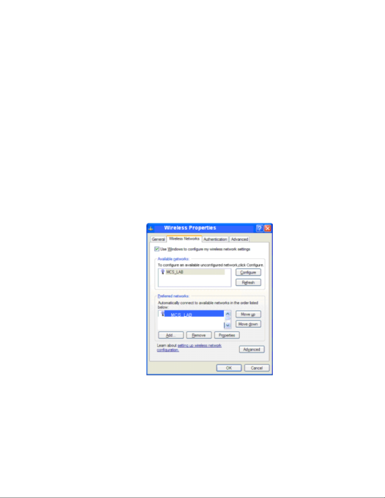
2. Select the SSID of the network to log on, and click Configure. This will
open up the Wireless Networks Properties window.
37
Page 38
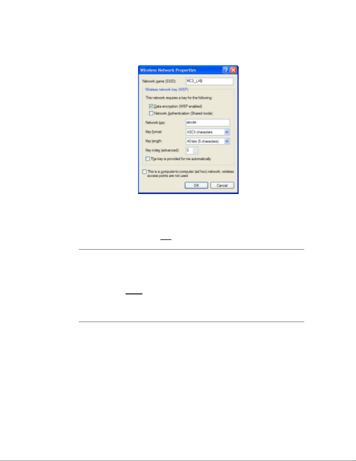
3. Ensure the WEP key is correct. If the Wireless LAN Card is used with
an access point, the checkbox This is a computer-to-computer (ad
hoc) network… should not be checked.
What is Ad-Hoc? A network mode that selects
communications & data access between wireless
computers only
. The alternative is Infrastructure mode
(data access between wireless computers, access points
and/or a wired LAN network).
4. Select OK. If you have Preferred Networks listed, consult the
Wireless Network section in Chapter 4 for information about
automatically connecting to those networks, depending on network
mode selected.
5. Select OK again at the Wireless Properties window.
38
Page 39
6. Finally, click Connect to connect the Wireless LAN Card to the
selected network. If there are still difficulties, consult Chapter 6,
Troubleshooting.
Advanced Windows XP Configuration
When selecting the Advanced button of the connect to wireless network
window, a window of four tabs appears. However, only the Wireless
Networks tab is required for network configuration of the Wireless LAN Card.
• General
• Wireless Networks – configuration of the Wireless LAN Card, scans for
available and preferred access points and networks
• Authentication
• Advanced
General Tab
39
Page 40

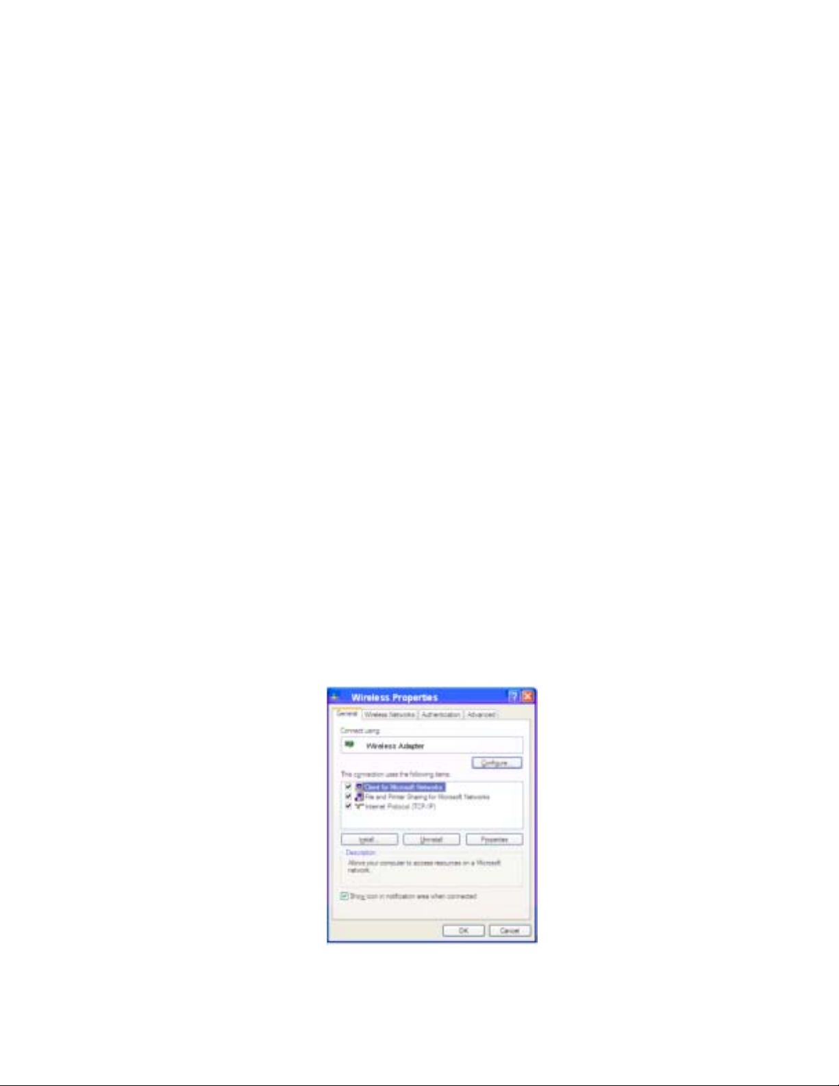
The General Tab is provided by Windows XP.
Screen options include
• Connect Using – shows the Wireless LAN Card
• Configure – (new window) shows typical connection protocols used (e.g.
Client for Microsoft Networks, Internet Protocol (TCP/IP) settings)
• Install- installs a new service.
• Uninstall-uninstalls a selected service.
• Properties – for each protocol
Show icon in notification area when connected - A check here will display
the connection status of the Wireless LAN Card in the System Tray area of
the Windows desktop.
40
Page 41
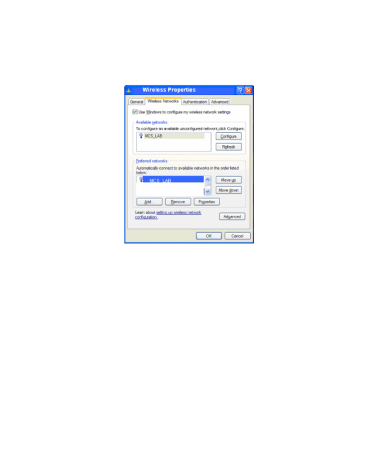
Wireless Networks window
The Wireless Networks tab displays a list of detected Access Points by
name (SSID) as well as the user’s preferred networks to connect to, using the
Wireless LAN Card.
If Use Windows to configure my Wireless Network settings check box is
checked, this allows Windows to configure wireless network settings for the
Wireless LAN Card.
The Available Networks box displays detected, available networks in the
area of the Wireless LAN Card. The SSID of the access points in those
networks are displayed.
41
Page 42

TIP: SSID is the name of the Wireless LAN network to
connect to. If some are detected, these will be displayed
on screen. Otherwise, enter a name to use. SSID is casesensitive. Always use the same spelling and case when
adding computers to the network.
Configure allows the user to add a network not configured yet (for use with
the Wireless LAN Card) and opens up the Wireless Network Properties
window (see below). After this card is configured for that network, it is added
to the Preferred Networks list.
Refresh will rescan the area for any networks and display the available
networks.
The Preferred Networks box displays the user’s network choices.
• Add – Adds a new network to this list, even those not in the Available
Network list. This option will open up the Wireless Network Properties
window (see below).
• Remove – Removes a selected network from the list.
• Properties – Opens up the Wireless Network Properties window (see
below), but does not allow changing the network name or type of network
(Access Point or Ad-Hoc).
• Move Up/Move Down – Changes the order of selected networks in the
Preferred Networks list. If this list has any Access Point networks, Ad-Hoc
networks cannot be placed ahead of them.
• Advanced – Allows selection of all or a subset of all the networks in the
Preferred Network list. No entries are removed from the list, but some
42
Page 43
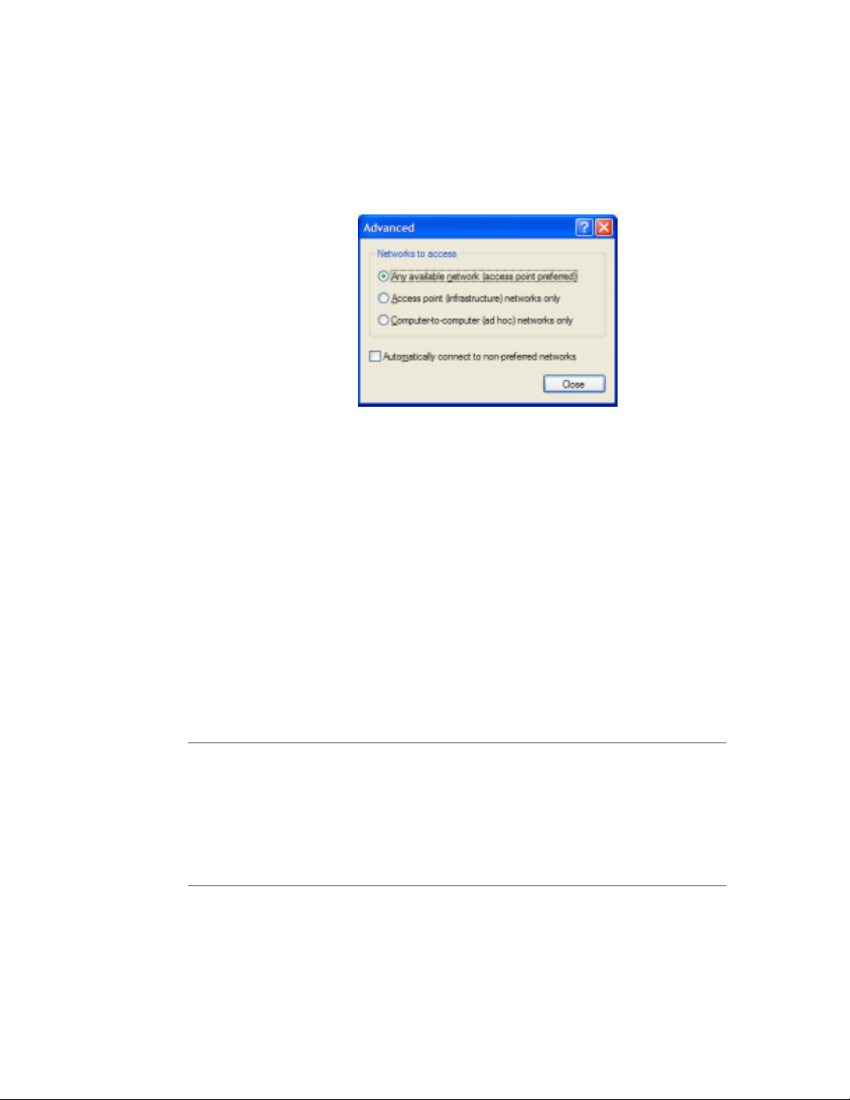
networks may not be displayed if they are not selected. Clicking Advanced
displays a new window with three choices.
• Any available network (access point preferred) - The Wireless LAN Card
will connect with networks using access points first, but all networks
including Ad-Hoc will be displayed.
• Access point (Infrastructure) networks only - The Wireless LAN Card
shall only connect with networks using access points.
• Computer-to-computer (Ad-Hoc) networks only - The Wireless LAN
Card connects only with Ad-Hoc networks.
TIP: The network mode selects Ad-Hoc communications
(data access between wireless computers) or
Infrastructure (data access between wireless computers,
access points and/or a wired LAN network).
43
Page 44

Based on the selection, all or a subset of all the networks in the Preferred
Network list are enabled and displayed. The remainders of the networks in
the list are disabled. This selection also decides which type of networks to
configure or add.
If the Automatically connect to non-preferred networks check box is
selected, then the Wireless LAN Card will try to connect any non-preferred
networks after it has tried all the networks in Preferred Network list without
any success.
After selection, Close will close this window.
Select OK to store these network settings and to attempt to connect the
Wireless LAN Card to the networks in the Preferred Network list. If
successful, the Wireless LAN Card will be connected to the chosen network.
Otherwise, the Wireless LAN Card will attempt to connect to the next network
in the Preferred Network list, until connected or until all choices have been
tried.
NOTE: If all the networks have been tried unsuccessfully, and the check box
Automatically connect to non-preferred networks is selected, then
the Wireless LAN Card will attempt to associate with any available SSID.
44
Page 45
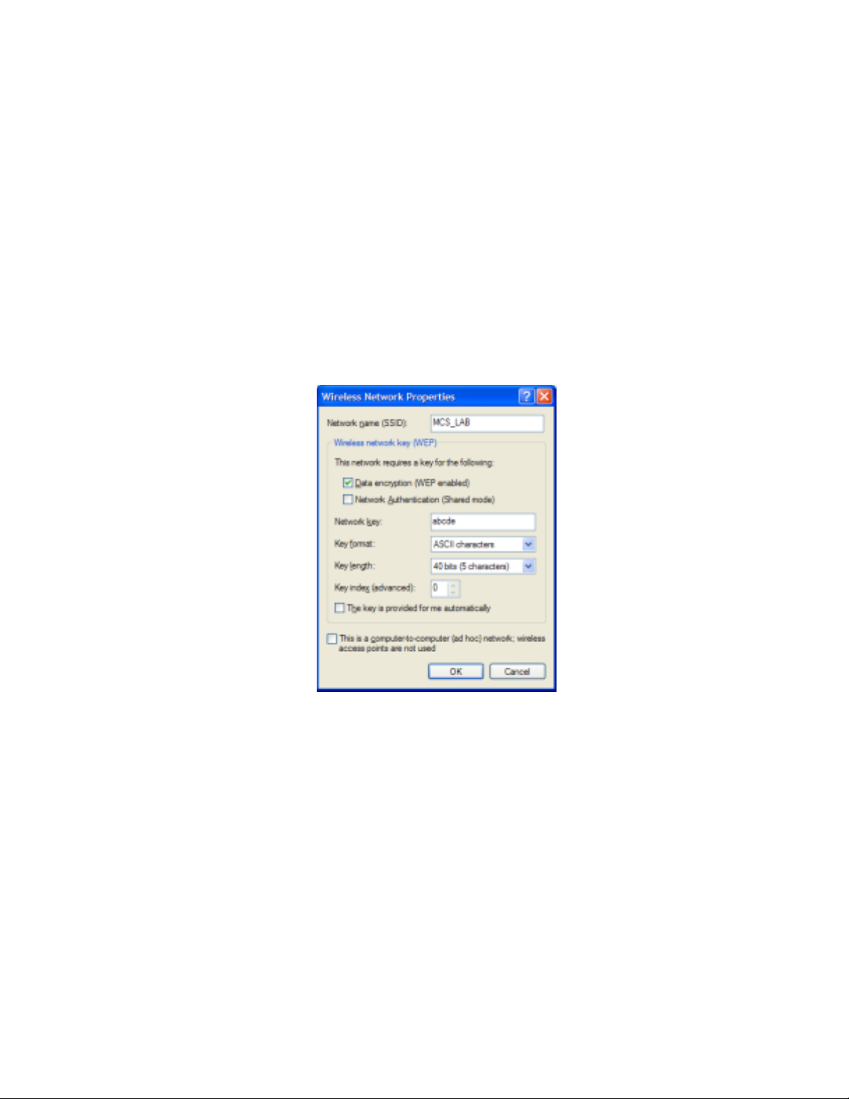
Wireless Network Properties Window
The Wireless Network Properties window allows the user to set properties
of the Wireless LAN Card for a particular network.
Network name (SSID) - The current network access point or the name of the
network being configured.
Data Encryption (WEP enabled) – A check here enables data encryption via
WEP. A WEP key is required beforehand.
45
Page 46

TIP: WEP is a protocol defined in 802.11i to provide
encryption capabilities for wireless LAN communications.
Because data travels through air, there is a likelihood of
unintended receivers listening in on your data
conversation. WEP encryption keys can be 40-bit
(minimal security) or 104-bit (more secure). Additionally a
WEP key is needed to encrypt and decrypt data packets,
and any computer on a WEP network must have the same
key, otherwise it will not be allowed on that network. It is
recommended that you select WEP encryption to reduce
security risks and unauthorized users from using the
wireless LAN network and access to important data.
Network Authentication (Shared mode) – This check box s hould be set if
you want to use WEP encryption for Network Authentication.
NOTE: If either of the above check boxes are checked, a new check box
opens up requesting the application providing the WEP key.
Network Key – The WEP key required for encryption.
Ensure that the WEP key entered here matches all other
applications and clients using the same network. WEP
keys can be case-sensitive, and incorrect keys will not
allow clients access to this network.
46
Page 47

Key Format – Choose Hexadecimal or ASCII characters.
Key Length – ASCII: Choose 40-bit (5 characters) or 104-bit (13 characters).
Hexadecimal: Choose 40-bit (10 digits) or 104-bit (26 digits).
Key Index – (0,1,2,3), reserved for use by vendor.
The key is provided for me automatically. This feature is only available
for devices that support 802.1x authentication. The Wireless LAN Card does
not support this form of authentication.
This is a computer-to-computer (Ad-Hoc) network; wireless access
points are not used – Selects Infrastructure or Ad-Hoc mode for this network.
Select OK to store these network settings in the Preferred Network list
database. Clicking OK will not connect the Wireless LAN Card to the network
yet.
NOTE: If OK is selected and the application finds that a network with the
same name and type already exists in Preferred Network list, an error
message will appear and changes to this network will be lost.
47
Page 48
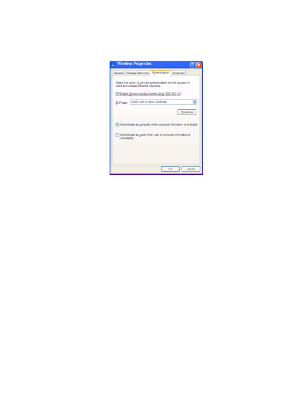
Authentication
The Authentication tab screen is provided by Windows XP.
Enable network access control using IEEE 802.1X – A check box here will
enable 802.1X advanced authentication and will request the user to choose
the EAP type from the selected list.
Authenticate as computer when computer information is available – This
checkbox will automatically login as a computer if the information is available.
If no information is available, checking the box Authenticate as guest when
user of computer information is unavailable will accomplish login.
Properties – Brings up the Smart Card or Other Certificate properties
screen to set the options for the EAP type, as follows:
48
Page 49
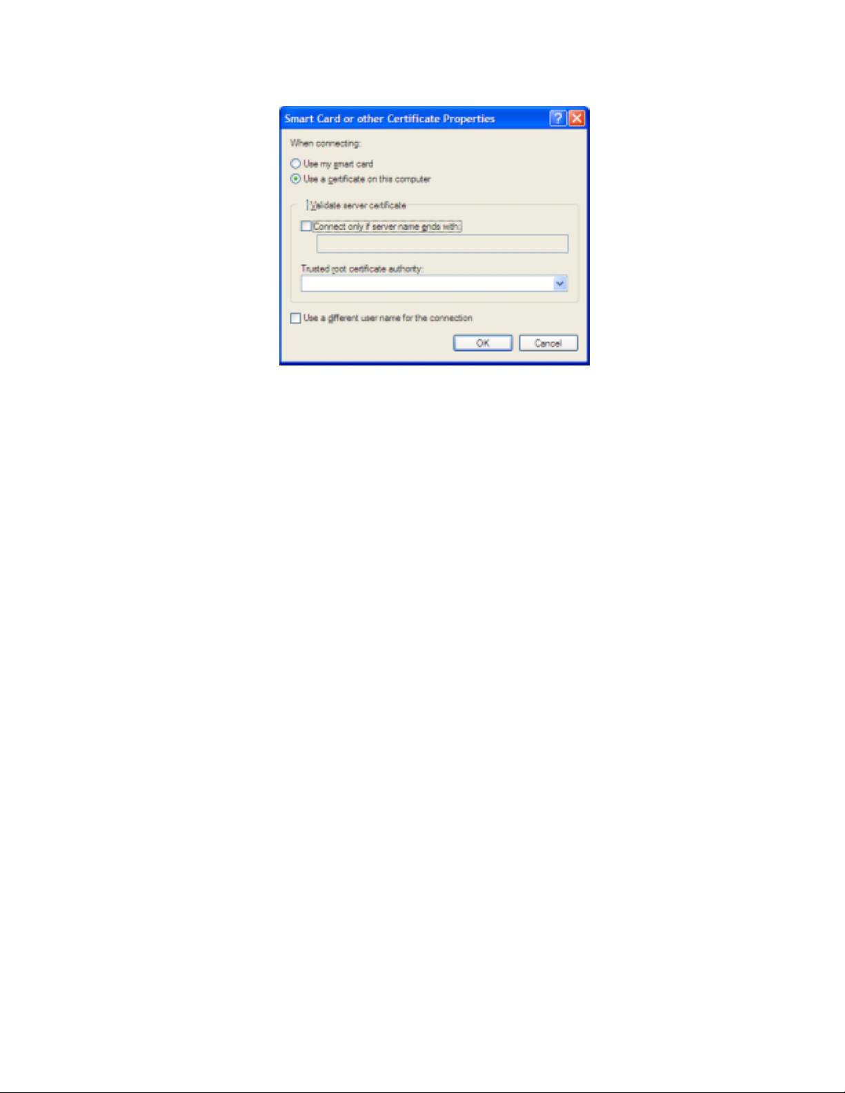
Choices include:
• Use my smart card- Select this option if a smart card is used for network
authentication and login.
• Use a certificate on this computer-If Validate server certificate box is
checked, two option boxes become available:
− Connect only if server name ends with appears if a specific server is
requested
− Trusted root certificate authority list of options appears to choose a specific
host certificate.
• Use a different user name for the connection – check this box to specify
a user name for this connection.
Advanced tab
49
Page 50
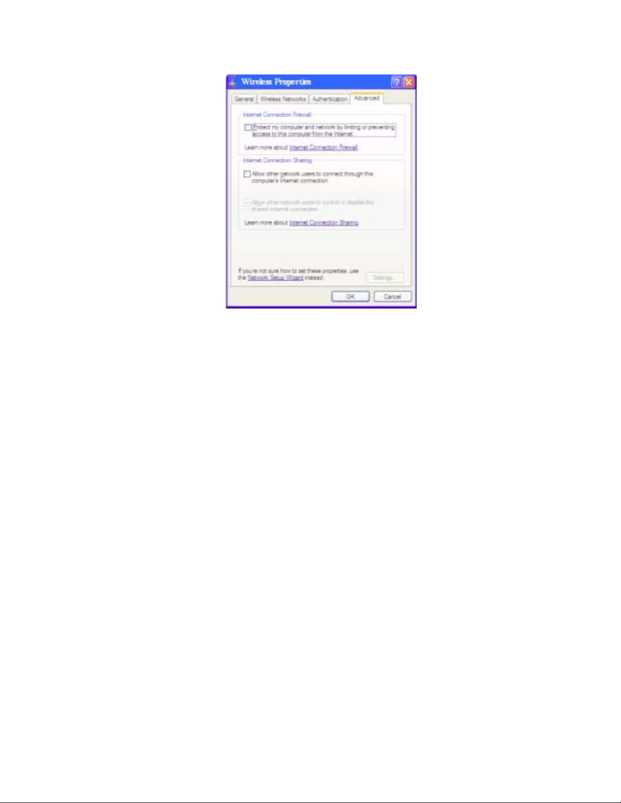
The advanced tab is provided by Windows XP.
Choices include
• Internet Connection Firewall – This checkbox will request Windows XP to
enable its firewall function for access to the Internet.
• Internet Connection Sharing – This checkbox will allow other computers
and user to use this computer’s connection for Internet access. If checked,
a second option will allow or restrict access to control or disable the shared
connection.
50
Page 51
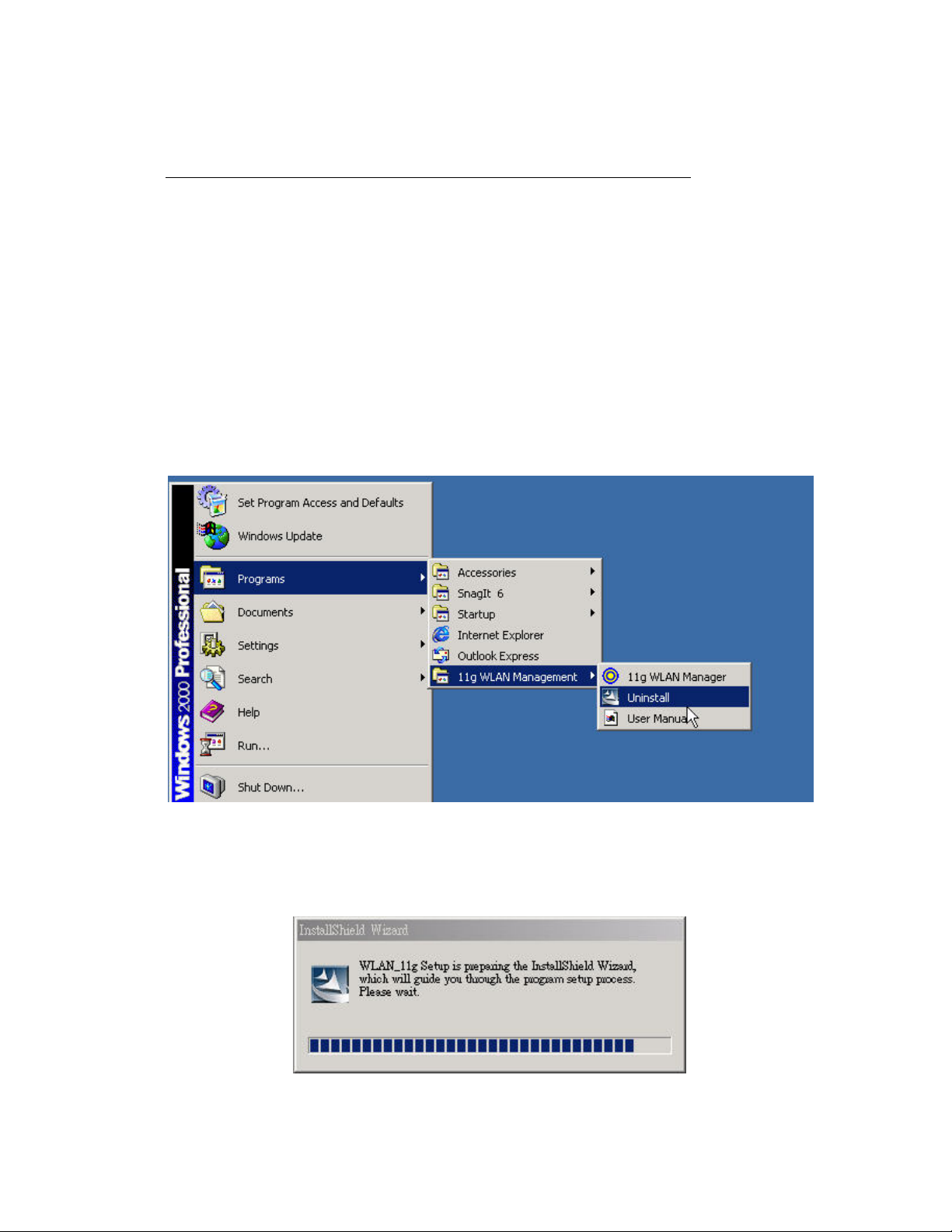
Chapter 5 Uninstall
Uninstall the WLAN Utility
1. To uninstall the 11g WLAN management Utility and Driver, choose
Start then Programs then 11g WLAN Management Utility, and click
Uninstall.
2. You will be asked if you want to uninstall the WLAN Utility and all of its
components.
51
Page 52
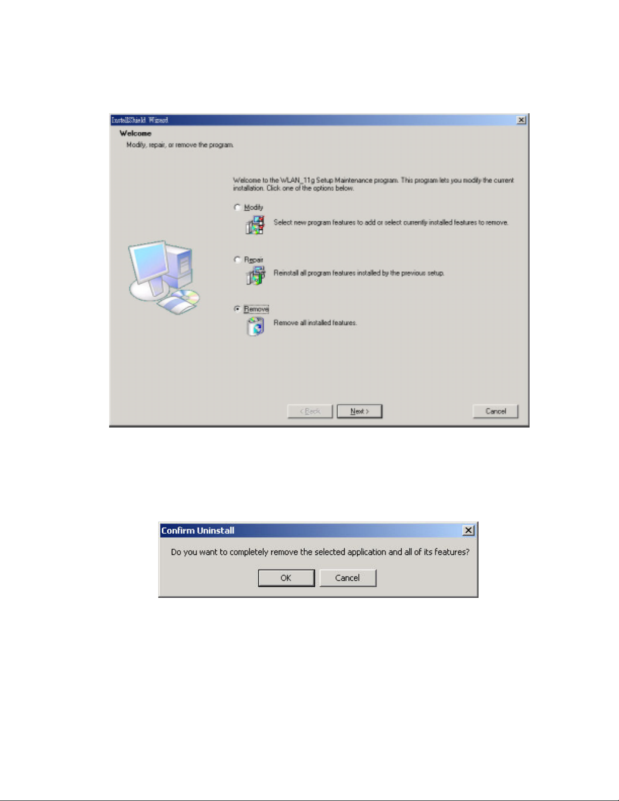
3. Click Remove option and Next button.
4. Click OK to remove or click Cancel to exit.
52
Page 53

Appendix A
Glossary
Access Point
A wireless LAN adapter, which connects to a wired LAN network (acting as a
bridge) and serves as the base for a wireless LAN network, directing
communication between clients. An access point is only used in Infrastructure
mode. Access Points in a business environment are typically connected to the
wired LAN network. In the home, an Access Point would be connected to a
broadband Internet device such as a Cable or ADSL modem.
Ad-Hoc
This is a wireless LAN network comprised solely of clients (no access points),
which can communicate with each other only when they are in range of each
other’s Signal and configured to the same channel and SSID.
BSS – Basic Service Set
This denotes the availability of access points and clients, all in communication
with each other. An Ad-Hoc LAN (clients only) may also have a BSS ID; all
machines must use the same BSS ID.
53
Page 54

Client
A PC, peripheral or other electronics with a connection to the network, with
the sole purpose of using the network for data access and transfer. For
example, a notebook PC with the Wireless LAN Card is considered a client.
ESS – Extended Service Set
The availability of access points and clients (BSS) and connections to wired
networks, as well as the ability for a client to roam. ESS is available in
Infrastructure mode, and all components must have the same ESS ID. Clients
within an ESS may roam freely through many BSSs, if they are within range
of the wireless LAN networks.
Infrastructure
As opposed to Ad-Hoc, this network mode allows connection to access points
and to wired LAN networks or Internet access device such as a cable or
ADSL modem.
LAN – Local Area Network
A network of clients/users typically based on the IEEE Ethernet protocol and
using TCP/IP (Internet Protocol).
54 55
Page 55

Roaming
Clients can freely move about the wireless LAN network (ESS).
WEP – Wired Equivalent Privacy
A shared-key encryption protocol used to provide security for wireless data.
At least two implementations of WEP exist, with keys based on the number of
bits (64 or 128-bit). The more bits in the key, the harder it is to decipher and
therefore, the more secure the connection is.
Page 56

FCC STATEMEMT:
This device is intended only for OEM integrators under the following
conditions:
1) The antenna must be installed such that 20 cm is maintained between the
antenna and users, and
2) The transmitter module may not be co-located with any other transmitter
or antenna.
As long as 2 conditions above are met, further transmitter test will not be
required. However, the OEM integrator is still responsible for testing their
end-product for any additional compliance requirements required with this
module installed (for example, digital device emissions, PC peripheral
requirements, etc.).
IMPORTANT NOTE: In the event that these conditions can not be met (for
example certain laptop configurations or co-location with another
transmitter), then the FCC authorization is no longer considered valid and
the FCC ID can not be used on the final product. In these circumstances, the
OEM integrator will be responsible for re-evaluating the end product
(including the transmitter) and obtaining a separate FCC authorization.
End Product Labeling
This transmitter module is authorized only for use in device where the
antenna may be installed such that 20 cm may be maintained between the
antenna and users (for example access points, routers, wireless ADSL modems,
and similar equipment). The final end product must be labeled in a visible
area with the following: "Contains TX FCC ID: SMW-GM-100".
Manual Information for End Users
The end user must not have manual instructions to remove or install the
device. The user manual for end users must include the following information
in a prominent location:
"IMPORTANT NOTE: To comply with FCC RF exposure compliance requirements, the
antenna used for this transmitter must be installed to provide a separation
distance of at least 20 cm from all persons and must not be co-located or
operating in conjunction with any other antenna or transmitter."
 Loading...