

Page 1

INSTRUCTION MANUAL
Cipher GenetiC AnAlysis system
DTSK-2001-110
DTSK-2001-220
DTSK-2401-110
DTSK-2401-220
One System that Detects Mutations and Polymorphisms 4 different ways:
1) DGGE - Denaturing Gradient Gel Electrophoresis
2) TTGE - Temporal Temperature Gradient Electrophoresis
3) SSCP - Single Strand Conformational Polymorphisms
4) CDGE - Constant Denaturant Gel Electrophoresis
1
Cipher Genetic Analysis System
www.cbsscientic.com
DTSK Instruction Manual, version 8/30/2011
Page 2

TABLE OF CONTENTS
Important User Information 3-4
Section 1 General Information
1.1 Introduction 5
1.2 Specications 6
1.3 Safety 6
Section 2 Description of parts
2.1 Unpacking 7
2.2 Components/Assembly 7
Section 3 Instructions for Use
3.1 Unit Set-up and Unpacking 8-9
3.2 Heater/Stirrer General Set-Up 10-24
3.3 Heater/Stirrer Programming 25-34
3.3.1 Setting Operational Parameters and Functions 25
3.3.2Entering/ModifyingaTemperatureProgram 26-30
3.3.3 Running a Temperature Program 31-32
3.3.4 Setting Preferences 32
3.3.5 Heater/Stirrer Error Messages 33-34
3.4 Running the Heater/Stirrer 35
3.5 Preparation/Cleaning of Glass Plates 35
3.6 GelCastingTechniques 36-37
3.7 Vertical Gradient Formation 38-42
3.8 Preparation of the Cassettes 43
3.9 Buffer Cycling Connections 44
3.10 Running the Gels 45
3.11 RemovingtheGels 46
3.12 Perpendicular Gel Casting 47
3.13 Perpendicular Gradient Formation 48-49
3.14 Buffer Siphon Pump Instructions for use 50
3.15 Maximum Well/Comb Volumes 50
Section 4 Running Conditions 51
4.1 Recommended Power 51
4.2 Recommended Buffers 51
4.3 Recommended Running Conditions 52
4.4 SSCP Running Conditions 52
4.5 References 53
Section5 MaintenanceofEquipment
5.1 Care and Handling 54
5.2 Maintenance & Calibration 55
Section6 Heater/StirrerTroubleshooting 56-57
Section 7 Accessories 58
2
Page 3

IMPORTANT USER INFORMATION
This Instruction Manual will explain how to use this product safely and effectively. Please read and carefully follow the
instruction manual in its entirety.
The triangle/exclamation mark symbol alerts the user of the product to important operational, maintenance, and/
or warranty requirements.
The triangle/lighting bolt symbol alerts the user of the product to potentially hazardous electrical exposure.
Failure to adhere to the instructions could result in personal and/or laboratory hazards, as well as invalidate any
warranty. Always turn off the DC power source prior to disconnecting power cords from the product. Disconnect
power cords from the power source rst, and then from the product. For maximum safety, always operate this
system in an isolated, low trafc area, not accessible to unauthorized personnel. Never operate damaged or
leaking equipment.
WARRANTY AND LIABILITY
This product was produced utilizing the highest practical standards of materials, workmanship, and design. C.B.S. Scientic
warrants that the product has been tested and will meet or exceed published specications. This warranty is valid only if
the product has been operated and maintained according to the instructions provided.
C.B.S. Scientic warrants this product to be free from defects in materials and workmanship under normal service for one
year from date of shipment. If the product proves defective during this period, C.B.S. Scientic will repair or replace it at our
option, free of charge, if returned to us postage prepaid. This warranty does not cover: damage in transit, damage caused
by carelessness, misuse or neglect, normal wear through frequent use, damage caused by solvent corrosion, damage
caused by improper handling or user alteration, nor unsatisfactory performance as a result of conditions beyond our
control. C.B.S. Scientic shall in no event be liable for incidental nor consequential damages, including without limitation,
lost prots, loss of income, loss of business opportunities, loss of use and other related damages, however caused, nor any
damage arising from the incorrect use of the product.
www.cbsscientic.com
3
Cipher Genetic Analysis System
DTSK Instruction Manual, version 8/30/2011
Page 4

FRANÇAIS INFORMATION IMPORTANTE À L’USAGE DES UTILISATEURS
Le présent manuel d’utilisation explique la manière de se servir efcacement du produit en conditions
de sécurité. Il est recommandé de soigneusement lire la totalité du manuel, avec ses consignes
et ses instructions.
Le triangle avec point d’exclamation est un symbole destiné à avertir l’utilisateur du produit
de l’importance de certaines exigences relatives au fonctionnement, à l’entretien et/ou à
la garantie.
Le triangle avec èche en zigzag est un symbole destiné à avertir l’utilisateur du produit de la
possibilité d’exposition à des décharges avec danger de secousses électriques.
Tout manquement à l’observation des consignes et des instructions peut exposer les personnes
et les biens à des dommages corporels et/ou matériels et peut annuler toute garantie. Il faut toujours
interrompre l’alimentation de courant continu avant de déconnecter les cordons d’alimentation du produit.
Déconnecter d’abord les cordons d’alimentation branchés sur la source de tension (alimentation de
secteur) puis ceux branchés sur le produit. Pour une sécurité maximum, il faut toujours faire fonctionner
ce système dans un lieu isolé, peu fréquenté, où le personnel non autorisé n’a pas accès. Ne jamais faire
fonctionner un matériel endommagé ou affecté par des fuites.
GARANTIE ET RESPONSABILITÉ
Le produit a été fabriqué conformément aux normes applicables les plus exigentes en matière de
matériaux, de main d’oeuvre, de conception et d’ingéniérie. C.B.S. Scientic garantit que le produit a subi
des essais et que ses performances rempliront les conditions des spécications publiées ou luer seront
même supérieures. La présente garantie n’est valide que si le produit a fonctionné et a été entretenu
conformément aux consignes et instructions fournies.
C.B.S. Scientic garantit que le produit sera dépourvu de vices de matériaux et de main d’oeuvre, en
conditions de service normales, pendant un an à compter de la date d’expédition. Au cas où le produit
s’avérerait défectueux pendant cette période de garantie, C.B.S. Scientic réparera ou remplacera le
produit, à sa discrétion et gratuitement, si le produit lui est retourné port payé d’avance. La garantie
ne couvre pas les dommages de transport; les dommages causés par l’imprudence, le manque de
soins, l’abus ou la négligence; l’usure normale résultant d’une utilisation fréquente; les dommages
causés par la corrosion des solvants; et les dommages causés par la manipulation inadéquate ou
des changements apportés par l’utilisateur. La garantie ne couvre pas non plus les performances non
satisfaisantes résultant de conditions hors du contrôle de C.B.S. Scientic. C.B.S. Scientic ne pourra
en aucun cas être tenue responsable de dommages indirects, y compris, de manière non limitative, la
perte de bénéces, le manque à gagner, la perte d’occasions d’affaires, l’impossibilité d’usage ou tous
autres dommages associés, quelle qu’en soit la cause, ni de dommages résultant de l’usage incorrect
du produit.
DEUTSCH WICHTIGE INFORMATION FÜR DEN BENUTZER
Diese Bedienungsanleitung beschreibt wie man dieses Produkt sicher und wirksam benutzt. Bitte lesen
und befolgen Sie alle Anweisungen in dieser Anleitung.
ESPAÑOL INFORMACIÓN IMPORTANTE PARA EL USUARIO
El presente instructivo explica la manera de usar este producto en forma segura y efectiva. Sírvase
leerlo en su totalidad y seguir detenidamente las indicaciones que contiene.
El símbolo del triángulo con exclamación llama la atención del usuario a requisitos
importantes para el uso y mantenimiento del producto, así como para la validez de
la garantía.
El símbolo del triángulo con rayo llama la atención del usuario a la posibilidad de riesgos
eléctricos.
El incumplimiento de las instrucciones aquí señaladas podría dar lugar a riesgos a la persona, al
laboratorio o a ambos y podría anular toda garantía. Siempre apague la fuente de corriente continua
antes de desenchufar los cables eléctricos del producto. Primero desconecte los cables de la fuente de
energía y después del producto. Para mayor seguridad, siempre use este sistema en un área aislada,
de poco movimiento de personas e inaccesible a personal no autorizado. Jamás use equipo que
presenta algún daño o fuga.
GARANTÍA Y RESPONSABILIDAD
Este producto fue fabricado de acuerdo con las normas más estrictas que sean factibles en cuanto a
materiales, mano de obra y diseño. C.B.S Scientic garantiza que se sometió el producto a pruebas y
que cumplirá o excederá las especicaciones publicadas. Esta garantía será válida únicamente si se
usa y se da servicio de mantenimiento al producto de acuerdo con las instrucciones señaladas.
C.B.S. Scientic garantiza que este producto se encontrará libre de defectos de materiales y mano de
obra por un período de servicio normal de un año a partir de la fecha de embarque. Si el producto resulta
defectuoso durante este período, C.B.S. Scientic lo reparará o lo repondrá, a criterio de C.B.S., libre
de cargos, si se devuelve el producto a C.B.S. porte pagado. Esta garantía no cubre daños sufridos en
tránsito, daños provocados por descuido, mal uso o negligencia, desgaste normal como consecuencia
del uso excesivo, daños atribuibles a corrosión provocada por solventes, daños causados por el uso
indebido o alteraciones realizadas por el usuario ni rendimiento insatisfactorio atribuible a circunstancias
fuera del control de C.B.S. Scientic. C.B.S. Scientic en ningún caso asumirá responsabilidad por
daños incidentales o subsecuentes, incluyendo, en forma no limitativa, la pérdida de utilidades, de
ingresos, de oportunidades comerciales o del uso del producto y otros daños anes, fuere cual fuere su
origen, ni por daños derivados del uso incorrecto del producto.
ITALIANO INFORMAZIONI IMPORTANTI PER L’UTENTE
Questo manuale spiega come utilizzare questo prodotto in maniera sicura ed efciente. Si pregai di
leggere e seguire con cautela le istruzioni di ogni parte di questo manuale.
Das Dreieck mit Ausrufezeichen weist den Benutzer des Produktes darauf hin, daß
wichtige Bedienungs-, Wartungs- und/oder Garantievorschriften zu beachten sind.
Das Dreieck mit Zickzackblitz warnt den Benutzer des Produktes vor möglichen
Gefahren durch elektrische Spannungen.
Nichtbeachtung dieser Anweisungen kann zu persönlichen und/oder labortechnischen Schäden
führen und gleichzeitig alle Garantien als nichtig erklären. Die DC Stromzufuhr muß immer, vor dem
Entfernen der Stromkabel vom Produkt, abgeschaltet werden. Die Stromzufuhrkabel müssen zuerst von
der Steckdose und erst dann vom Produkt entfernt werden. Um höchste Sicherheit zu gewährleisten
sollte dieses System in einem abgesonderten und besonders ruhigen Bereich eingesetzt werden und
vor Unbefugten sicher sein.
GARANTIE UND HAFTUNG
Dieses Produkt wurde unter Anwendung von Produkten mit höchster Qualität und aus Materialien mit
bester Verarbeitung und modernstem Design hergestellt. C.B.S Scientic garantiert, daß das Produkt
getestet wurde und alle publizierten Spezikationen übertrifft. Diese Garantie ist jedoch nur gültig, wenn
das Produkt nach der beigefügten Bedienungsanleitung bedient und gewartet wurde.
C.B.S. Scientic garantiert, daß dieses Produkt bei normaler Bedienung aus fehlerfreiem Material
besteht und fehlerfrei in der Ausführung ist. Diese Garantie gilt für ein Jahr ab Lieferdatum. Sollte
das Produkt in diesem Zeiraum fehlerhaft werden, bietet C.B.S. Scientic eine kostenlose Reparatur
bzw. Kostenlosen Ersatz, einschließlich freiem Rückporto. Diese Garantie schließt folgendes aus:
Transportschaden, Schaden durch Nachlässigkeit, Mißbrauch oder Vernachlässigung, normale
Abnützung durch regelmäßigen Gebrauch, Schaden durch Säureangriff, Schaden durch falsche
Handhabung, Veränderung des Produktes durch den Benutzer, oder unzureichende Leistungen die
sich nicht im Verantwortungsbereich von C.B.S. Scientic benden. C.B.S. Scientic kommt unter
keinen Umständen für folgende Schäden auf: Sachschadensverlust, Einkommensverlust, Verlust
von Geschäftsmöglichkeiten, Verlust der Anwendung und andere damit verbundene Schäden die auf
irgend eine Art und Weise entstanden sind, oder Schäden die aus falscher Anwendung des Produktes
entstanden sind.
Il triangolo contenete il simbolo di un punto esclamativo avverte l’utente di importanti
requisiti relativi al funzionamento, manutenzione e/o garanzia del prodotto.
Il triangolo contenete il simbolo di un lampo avverte l’utente del prodotto della possibilità
di pericoli dovuti a corrente elettrica.
La mancata osservanza delle istruzioni può essere causa di pericolo alla propria persona ed
al laboratorio, oltre a poter annullare la garanzia. Prima di distaccare il cordone d’alimentazione dal
prodotto, spegnere sempre la sorgente di corrente continua. Distaccare i cordoni d’alimentazione prima
dal lato della sorgente di tensione e poi dal lato del prodotto. Per maggior sicurezza, mettere sempre
in funzione il prodotto in un’area isolata con poco trafco che non sia accessibile al personale non
autorizzato. Non mettere mai in funzione un’apparecchiatura che sia danneggiata o abbia perdite.
GARANZIA E RESPONSABILITÀ
Questo prodotto è stato fabbricato seguendo gli standard più elevati per i materiali, la manodopera e la
progettazione. La C.B.S. Scientic garantisce il prodotto è stato sottoposto a prova e raggiunge o supera
i valori pubblicati per i dati tecnici. Questa garanzia è valida solo se il prodotto è messo in esercizio e
soggetto a manutenzione secondo le istruzioni fornite.
La C.B.S. Scientic garantisce che questo prodotto è libero di difetti di materiali e manodopera, in normali
condizioni d’esercizio, per la durata di un anno dalla data di spedizione. Se, in questo periodo, il prodotto
si dimostrerà difettoso, la C.B.S. Scientic, a suo giudizio, lo riparerà o sostituirà. Questa garanzia non
copre danni in transito, danni causati da negligenza, uso improprio, trascuratezza, normale consumo
derivante da uso frequente, o danni causati da solventi corrosivi, danni causati da maltrattamento o da
modiche apportate dall’utente e non copre prestazioni insoddisfacenti che siano il risultato di condizioni
al di fuori del controllo del fabbricante. La C.B.S. Scientic non sarà in ogni caso responsabile per danni
incidentali o consequenziali, incluso, senza limitazioni, perdite di protto, perdita di entrate, perdita di
opportunità d’affari e altri danni relativi, comunque causati, e per danni risultati da uso incorretto del
prodotto.
4
Page 5

SECTION 1
General Information
1.1 Introduction
DESCRIPTION
The Cipher GenetiC AnAlysis systems (DTSK-2001 and DTSK-2401) allow the researcher to choose which technique
is most applicable to their investigation. Both DGGE and TTGE rely on establishing a gradient of either solvent
(Urea/Formamide) or temperature in which the target fragments will undergo conformational transition (melt). This
sequence dependent information will determine the theoretical melting behavior of the target fragment after PCR
amplication. If the sequence is known, then primer/probe design can be made using certain software design
programs (1). If not, the melting range can be revealed by running perpendicular DGGE/TTGE gels. The third
mutation detection technique, SSCP, differentiates between normal and mutant duplex DNA by denaturing the DNA
to form single stranded molecules of equal length. These molecules can re-anneal onto themselves and based on
the varying degree of intrastrand base pairing, form different three-dimensional structures. These structures, differ
in electrophoretic mobility and can be separated on a non-denaturing polyacrylamide gel.
C.B.S. SCIENTIFIC has designed two different Cipher GenetiC AnAlysis systems which are reliable and easy-to-use.
The DTSK-2001 is a 2 gel system and includes two single gel cassettes. The DTSK-2401 is a four gel system which
includes two dual gel cassettes. The systems feature: programmable heater/stirrer which can be programmed for
DGGE, TTGE and SSCP applications, a large diameter cooling coil for use with an external chiller, a simplied
method for casting perpendicular and vertical gels using Gel Wrap®, single or dual gel cassettes, an internal
impellor pump for buffer cycling, polypropylene spring clamps, and a safety cover with an electrical interlock which
helps maintain temperature, reduce evaporation, and protect against shock hazard.
DGGE & CDGE
Denaturing Gradient Gel Electrophoresis (DGGE) is a powerful genetic analysis technique that can be used for
detecting single base changes and polymorphisms in genomic (2,3), cloned, and PCR amplied DNA (3,4). Two
of the most valuable uses for DGGE in human, animal or microbial genetics are in directly detecting single base
changes that cause disease and in detecting polymorphisms with DNA probes for genetic-linkage analysis. In DGGE,
conformational transitions of multiple nucleic acid complexes are induced by an increasing concentration of solvent
(Urea/Formamide) at a constant temperature. Clinical applications of DGGE include a rapid and effective method
for screening samples for genetic mutations and variants. Also, DNA fragment melting points can be determined
using perpendicular DGGE (2). In contrast to DGGE, CDGE (Constant Denaturant Gel Electrophoresis) uses a
single solvent percentage to induce partial melting of DNA fragments as they enter the gel. The disadvantage of
CDGE is that only a single melting domain can be interrogated.
TTGE
Destabilization of nucleic acid complexes can also be studied using acrylamide gels which contain a uniform solvent
concentration (Urea/Formamide), but with an increasing temperature gradient (6). Since the temperature of the
entire gel is uniformly raised over a period of time, this technique has been termed ‘TTGE’, or Temporal Temperature
Gradient Electrophoresis (7). This technique incorporates many improvements over DGGE/CDGE especially when
studying multiple melting domains (8).
SSCP
Single Strand Conformational Polymorphism (SSCP) reveals differences in electrophoretic mobility between normal
and mutant single strands of DNA (9). In SSCP, normal and mutant duplex DNA are denatured to form single stranded
molecules of equal length. These molecules can re-anneal onto themselves and based on the varying degree of
intrastrand base pairing, form different three-dimensional structures. These structures, differ in electrophoretic
mobility and can be separated on a chilled non-denaturing polyacrylamide gel. The electrophoretic mobility of
these “conformers” change depending on temperature and buffer ionic strength. For accurate characterization
of mutations within these re-folded single strands, it is essential that the buffer temperature be tightly controlled
within each electrophoresis procedure, usually between 4º-25ºC. If the gel temperature is not precisely controlled,
the resolution will suffer because of the loss of intrastrand base pairing and change in the overall shape of the
3-dimensional conformer.
www.cbsscientic.com
5
Cipher Genetic Analysis System
DTSK Instruction Manual, version 8/30/2011
Page 6
1.2Specications
Constructions
DTSK Tank Sodalime glass, Kydex
DTSK Lid Sodalime glass, Kydex
Electrodes Platinum wire .012” diameter
Power cords FR Polypropylene/Silicone, rated 7500V, 200mA, 65° C
DTSK Cassette Acrylic
Cooling Coil brass, copper, PVC
Heater/Stirrer Buffer Cycler Stainless steel
Combs Teon/ Acrylic
Spacers Proprietary
Glass Plates Sodalime or Borosilicate
Gradient Maker Acrylic, teon, stainless steel
DTSK-2401
Gel Size
Distance between electrodes
Voltage limit
17.7cm x 22cm
20cm
250
1.3 Safety
Power to the DTSK Systems is to be supplied by an external DC voltage power supply that must be ground isolated
so that the DC voltage output oats with respect to ground. For any power supply used, the maximum specied
operating parameters for the units are:
Maximum Limits
250 VDC voltage
60 watts power
1600 mA current
70°C ambient temperature
Current to the unit, provided from the external power supply, must enter the unit through the lid assembly, providing
a safety interlock to the user. Current to the unit is broken when the lid is opened. Do not attempt to use the unit
without the safety lid. Always turn the power supply off before removing the lid, or when working with the
unitinanyway.Followsafetyprecautionsspeciedbythepowersupplymanufacturer.
6
Page 7

SECTION 2
Heater
Stirrer
Buffer Siphon
Pum p Assemb ly
TTG E
Tank
Dual
Cassette (2)
Com b (4 )
Spacers
(4 pairs)
Glass Plate
Assembly(4)
Clamps
Mini-Pump
(Optiona l)
GM-40
Gelwrap
®
(4)
Description of Parts
2.1 Unpacking
Please verify that your Cipher GenetiC AnAlysis system comes complete with the following components:
• Lower Reservoir/Glass tank/safety interlock/ with 2 black leads inside lid
• Heater/Stirrer/By-pass pump/Cooling Coil
• Two Dual Gel cassettes
• 1 Gradient maker, 20mls per side, Cat. # GM-40
• 8 each combs, 4 sets glass plates, 8 pair spacers and 8 each Gel Wrap gaskets
• White spring clamps, 12 each GPC-0002-177 and 16 each GPC-0001-177 (Number of clamps received with
system will vary depending on format of DGGE)
• Buffer siphon pump with tubing, Cat. # BSP-100
• EPS-300-II Power Supply
• Peristaltic Mini-Pump for gel casting
2.2 Components/Assembly
www.cbsscientic.com
7
Cooling coil is
situated inside tank
below heater/stirrer
Cipher Genetic Analysis System
DTSK Instruction Manual, version 8/30/2011
Page 8
SECTION 3
Instructions for Use
3.1 Unit Set-up and Unpacking Instructions
1. Unpack lower reservoir and place on level surface in an approved location.
2. WARNING:DoNOTturnonHeater/Stirreruntiltankhasbeenlledwithbuffer. The MINIMUM buffer
volume for heating is 23 liters. Turning Heater/Stirrer on with less than 23 liters of buffer will damage the
heating coil, and void warranty. If running two dual cassettes, the buffer volume is 24 liters.
3. Connect cooling coil to chiller using tubing adapters and 1/4th I.D. tubing (tubing is not supplied).
Fig. 3-1
cooling coil inlet
and outlet
heater/stirrer
8
Page 9

3.1 Unit Set-up and Unpacking Instructions-continued
4. Position an appropriate power supply on a shelf above the tank.
5. Fill the tank with running buffer. To obtain the correct level of buffer, place the cassettes in the tank and ll
the tank until the level of buffer reaches the underside of the upper reservoir. The upper reservoir holds only
50mls.
6. Attach the power supply to the safety interlock. (Fig 3-2-A)
7. Attach the safety interlock to a wall (mains) outlet. (Fig 3-2-B)
8. Plug the Heater/Stirrer into a wall (mains) outlet. Important: Do not plug the heater/stirrer into anything other
than a wall outlet.
9. Do NOT attach power leads (from power supply to safety interlock, Fig 3-2-C) until gels are loaded and
installed in the tank.
Power Supply/Safety Interlock Connections
Fig. 3-2
www.cbsscientic.com
C
B
A
9
Cipher Genetic Analysis System
DTSK Instruction Manual, version 8/30/2011
Page 10
3.2 Heater/Stirrer Set-Up and Programming
3.2a General Information
Model Type Temperature
Heat Only
Immersion Circulator
Circulator Pump
Pump speed is selected via the Main Menu. The MINIMUM setting is used for DGGE applications.
MAXIMUM is recommended where temperature varies frequently and there is a need for fast recovery or when
pumping to multiple external units.
Speed Maximum Pump Outlet Ratings Maximum Pump Outlet Ratings
Selection Line Frequency = 60Hz Line Frequency = 50Hz
MAXIMUM 30 LPM / 5.0 PSI 22 LPM / 3.4 PSI
HIGH 24 LPM / 2.5 PSI 20 LPM / 1.7 PSI
MEDIUM 20 LPM / 1.7 PSI 17.5 LPM / 1.2 PSI
LOW 18 LPM / 1.2 PSI 15.8 LPM / 0.8 PSI
MINIMUM 15.7 LPM / 0.8 PSI 15 LPM / 0.7 PSI
Range
Ambient +5°C to
200°C*
Reservoir
Capacity
N/A 11A 9.7A
Amps @
120V,60Hz
Amps @
240V, 50Hz
The data in the table above are based on the following criteria:
a. Maximum pump outlet ow rate is measured in liters per minute (LPM) with no restriction on the pump outlet.
b. Maximum pump outlet pressure is measured in pounds per square inch (PSI) at no ow.
c. Water was used as the circulation uid. Water has a viscosity of one centistoke. High viscosity or low-density uids will change
these gures.
Filling the Reservoir
A liquid level that fully covers the heater coil, pump, over-temperature sensor, and at least one inch
(25mm) of the temperature sensor must be maintained. For heating applications, the DTSK tank must
have at least 23 liters of buffer. When running the system with two dual cassettes, buffer volume should
be 24 liters.
Temperature Sensor
minimum ll level
10
Page 11

3.2 Heater/Stirrer Set-Up and Programming – continued
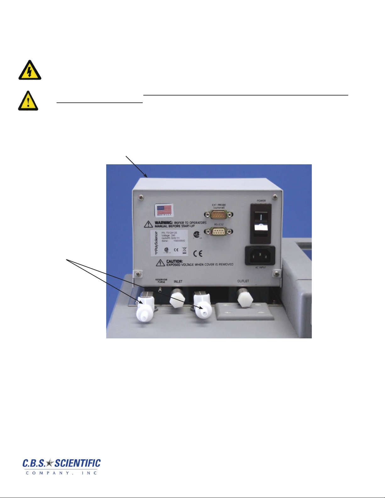
3.2b Front and Rear Panels
2
3
4
Front View Rear View
1
5
6
8
9
7
10
11
12
1. Select / Set Knob 10. Identication Label
2. LCD Display 11. Reservoir Purge
3. Safety Set Indicator Knob 12. Pump Inlet (Do NOT open)
4. Safety Set Reset Button 13. Pump Outlet (Do NOT open)
5. Timer Button 14. AC Input
6. Escape Button 15. External Probe Connection
7. Power On/Off Button 16. RS232 Interface
8. Heating Light 17. Circuit Breaker / AC Power Switch
9. Cooling Light1
1
Active on Refrigerating/Heating Circulating Baths only
2
Functional on Programmable Controller only.
15
16
14
2
17
13
www.cbsscientic.com
Heater/Pump Assembly
1
2
3
1. Temperature Sensor
2. Pump Shaft and Impeller
3. Over-Temperature Sensor
4. Heater Coils
4
11
Cipher Genetic Analysis System
DTSK Instruction Manual, version 8/30/2011
Page 12

3.2 Heater/Stirrer Set-Up and Programming – continued
3.2cSpecications
Temperature Stability
Controller / RS232 Yes
External Temperature Probe Functional on Programmable models / optional external
Readout Accuracy Graphic LCD, °C or °F, ±0.25°C
Heater 1100W – 115V, 2200W – 240V
Pressure Flow Rate 15.7 to 30 LPM (60Hz); 15 to 22 LPM (50Hz)
Suction Flow Rate 11 to 22 (60Hz); 10 to 15 LPM (50Hz)
Over-Temperature Protection Yes, user-adjustable
Low-Liquid Protection Yes
Pump Speeds Five-speed adjustable
1. Temperature stability may vary depending on bath volume, surface area, insulation, and type of uid.
NOTE: Performance specications determined at ambient temperature of 20°C (68°F).
1
±0.01°C
probe required
Not functional on Digital models
Environmental Conditions:
• Indoor Use Only • Over Voltage: Category ll
• Maximum Altitude: 2000 meters • Operating Ambient: 5° to 30°C
• Relative Humidity: 80% for temperatures to 30°C • Pollution Degree: 2
• Class 1: Residential, Commercial, Light Industrial • Class 2: Heavy Industrial
12
Page 13

3.2 Heater/Stirrer Set-Up and Programming – continued
3.2d Circulator Location
Locate the Circulator on a level surface, free from drafts and out of direct sunlight. Do not place it where corrosive
fumes, excessive moisture, high room temperatures, or excessive dust are present.
Refrigerating/Heating Circulators must be a minimum of four inches (102mm) away from walls or vertical surfaces so
air ow around the unit is not restricted.
To help prevent voltage drops, position the Circulator as close as possible to the power distribution panel and a
properly grounded outlet. The use of an extension cord is not recommended.
Warning: These units are equipped with over-temperature protection (Safety Set). A low liquid level or failure to set
the Safety Set and properly immerse the heater may result in heater burnout and triac failure. While operating, do not
allow the heater to contact any potentially ammable materials, such as plastic racks or the sides of plastic tanks, as
a re hazard may result.
3.2eReservoirLiquidLevel
Fill the reservoir with the appropriate buffer. On circulating baths, the liquid level should be sufcient to cover the
heating coils, cooling coils (if applicable), pump, over-temperature sensor, and at least one inch (25mm) of the
temperature sensor. The level should be at the ll line indicator on the tank.
After lling the reservoir with uid, you must set the Safety Set and the Limit High value as well as your desired
control set point temperature.
3.2f External Temperature Probe
The Programmable Controller is designed to accommodate an optional remote temperature probe. The probe
attaches to the 9-pin male D-connector on the rear panel of the Controller.
NOTE: On Digital Controllers, this connection is present, but not functional.
The Controller will automatically sense the presence of the external probe when main power (rear panel circuit
breaker/power switch) is turned On. To control temperature using the external probe, “External” must be selected via
the Controller’s software. You must also set a Maximum Setpoint Differential value.
To attain better temperature uniformity when using the external temperature probe in a jacketed or air-lled vessel,
stirring the external uid with pumps or mixing air with fans is recommended. Expect only ±1.0°C stability with air or
any medium that does not conduct heat well. Insulate and cover the entire set-up to remove temperature gradients;
the Controller cannot compensate for external chamber or component temperature gradients.
3.2g RS232 Interface
Programmable and Digital Controllers incorporate an RS232 interface to provide remote data-logging and control
capability. Remote control capability is available on the Programmable Controllers only. The 9-pin female RS232
connector is located on the rear panel of the Controller.
The RS232 interface should be connected to a serial communication port on a remote PC using an appropriate cable.
Communications software compatible with Microsoft® Excel and National Instruments LabView™ are provided with
Programmable Controllers. Contact Technical Service at C.B.S. Scientic technicalservice@cbssci.com
www.cbsscientic.com
13
Cipher Genetic Analysis System
DTSK Instruction Manual, version 8/30/2011
Page 14

3.2 Heater/Stirrer Set-Up and Programming – continued
3.2h Power
An IEC power cord is provided with the Circulator. This power cord should be plugged into the IEC receptacle on the
rear of the Controller and then plugged into a properly grounded outlet. Make sure that the power outlet is the same
voltage and frequency indicated on the identication label on the back of the Controller.
The use of an extension cord is not recommended. However, if one is necessary, it must be properly grounded and
capable of handling the total wattage of the unit. The extension cord must not cause more than a 10% drop in voltage
to the Circulator.
Once the unit has been connected to an appropriate electrical outlet, place the Circuit Breaker/Power Switch on the
rear of the Controller in the ON position. The unit will run through a self-test.
The rst time power is applied to the Controller, the following display will appear. This display allows you to select
the language that will be used for all subsequent displays. The instructions for selecting a language will be briey
displayed in each available language.
NOTE: The language selection display only appears the rst time the Controller is powered up.
When the language selection display appears, rotate the Select/Set Knob until the desired language is highlighted
and then press the Select/Set Knob. The Controller will continue with the start-up sequence and then display
“Standby” on the LCD.
DO NOT place the Power Switch on the front of the Controller ON until the Safety Set has been adjusted to the
desired temperature.
3.2i Setting the Safety Set Point
The Safety Set feature automatically disconnects Controller power to the heater and pump in the event that the
reservoir liquid level drops too low or the sensed temperature exceeds the Safety Set temperature. The Safety Set
is user-adjustable between approximately 40° and 210°C. It should be set at least 5°C higher than the desired bath
temperature.
Use a at blade screwdriver to rotate the Safety Set Indicator Knob to the desired temperature.
Do not force the knob beyond the stops at either end of the temperature value range.
If the Safety Set temperature is exceeded during normal operation, a fault message will ash on
the display and power to the heater and pump will be disrupted. To reset the fault, correct the problem (low liquid
level, incorrect Safety Set temperature, etc.), press the Safety Set Reset Button, and then the ESC Button. Normal
operation will resume.
3.2j Power On
Once the Safety Set temperature has been set, turn power to the Controller ON by pressing the Power Switch on the
front of the Controller. The following message will appear briey on the display:
14
Page 15

3.2 Heater/Stirrer Set-Up and Programming – continued
The pump will begin operating; the display will show the current bath temperature and the set point temperature
(Setpoint). If an external probe (Programmable Controllers only) is connected, both the internal and external bath
temperatures will be displayed. The temperature probe selected to control bath temperature (internal or external) will
be displayed in larger numerals.
NOTE: If the external temperature probe is selected to control bath temperature, but the temperature difference
between the set point temperature and the internal bath temperature exceeds the Maximum Setpoint Differential
setting, the heating rate will be controlled using the internal bath temperature until the set point/internal bath
temperature difference is within the Maximum Setpoint Differential value. The word Internal will be highlighted on the
display to indicate that the internal sensor is controlling bath temperature.
3.2k Local Lockout
This enables the user to lock all controls on the controller. While the feature is activated, the unit will remain running
at the current settings.
To activate the local lockout feature, press and hold the Select/Set Knob for 10 seconds. Once locked, “LocalLock”
will appear in the upper left corner of the display. The controller menus may still be viewed when Local Lockout is
active, but no changes may be made.
Press and hold the Select/Set Knob again for 10 seconds to unlock the controls. Once unlocked, “LocalLock” will
disappear and the menu settings can once again be modied.
LocalLock
3.2l Setting the Bath Temperature Set Point
Press and release the Select/Set Knob. The “whole” numbers in the set point temperature will be
highlighted. Rotate the Select/Set Knob clockwise to increase the displayed value; rotate the knob
counter-clockwise to decrease the displayed value.
Press the Select/Set Knob to accept the new value. The decimal value in the set point temperature digits
will be highlighted. Rotate the Select/Set Knob clockwise to increase the displayed value; rotate the knob
counter-clockwise to decrease the displayed value. Press the Select /Set Knob to accept the new value.
NOTE: Increasing/decreasing the decimal value past “0” will cause a corresponding change in the “whole”
number value. For example, if the current set point value is 24.8 and the desired value is 25.2, it is not
necessary to change the 24 to a 25; increasing the decimal value from .8 to .2 will automatically increase
the 24 to 25.
The Controller will not allow you to enter a set point value above the Limit High setting or below the Limit
Low setting. Should you attempt to do so, the set point value will stop increasing/decreasing when the
Limit value is reached and a Warning message will appear on the display. You must either change the set
point or change the Limit value. Reference the Heater/Stirrer instruction manual for detailed information.
www.cbsscientic.com
15
Cipher Genetic Analysis System
DTSK Instruction Manual, version 8/30/2011
Page 16

3.2 Heater/Stirrer Set-Up and Programming – continued
3.2m Menu Navigation
Main Menu — To view the Main Menu items, rotate the Select/Set Knob. Continue turning the Select/Set Knob to
scroll through the Main Menu displays.
To begin programming or view the options available in a Main Menu item, press the Select/Set Knob. The rst
available sub-menu item (or the last item in that sub-menu which was selected) will be highlighted like
To de-select an item, press the ESC Button. To return to the main operational display, press the ESC Button a second
time or allow the display to timeout.
Sub-Menu Selections — To select an item in a sub-menu, press the Select/Set Knob. The rst available item (or the
last item in that sub-menu which was selected) will be highlighted. Rotate the Select/Set Knob clockwise to advance
to the next sub-menu item; rotate the knob counter-clockwise to go back to the previous item. Press the Select/Set
Knob to select the highlighted item; the highlighting will change from to , indicating that the
displayed value or choice may be changed.
Entering and/or Changing Sub-Menu Values — Once the desired sub-menu item has been selected (as described
above), the displayed value is changed by rotating the Select/Set Knob. The change is accepted by pressing the
Select/Set Knob. On sub-menu items requiring multiple entries, such as hours/minutes/seconds, an underline will
appear under the rst value in that sequence which can be changed. (Example: 01:23:00 ) To accept the displayed
value and/or advance to the next value in the sequence, press the Select/Set Knob. To return to the previous cursor
position, such as from minutes back to hours, press the ESC Button. Once a value has been entered and accepted,
the highlighting box around the value will disappear. If you do not wish to accept the displayed value, press the ESC
Button or allow the display to timeout before pressing the Select/Set Knob.
THIS
THIS
THIS
16
Page 17

3.2 Heater/Stirrer Set-Up and Programming – continued
3.2n Menu Structure
Main Menu Item
Timer
Program
Run Program
1
1
Preferences
Limits / Alarms
Associated
Sub-Menu Items
Set
Beep
Program #
Program Steps
Program Loops
Step #
Step Setpoint
Minutes/Seconds
View Prole
Program #
Program Status
Readout
Units
Sound
Language
Program
1
Limit High
Alarm High
Alarm Low
Limit Low
Choices / Ranges / Comments
00:00:00 to 99:59:59
On or Off
1 to 10
1 to 50
1 to 99
1 to 50
–50° to 200°C (-50° to 392°F)
0 second to 999 minutes, 59 seconds
Displays temperature prole of program.
1 to 10
Start, Starting, Running, Paused, or Completed
#, #.#, or #.## (0, 1, or 2 decimal places)
°C or °F
1 to 100
English / French / German / Spanish
Time / Temperature
-50° to 200°C (-58° to 392°F)
-50° to 200°C (-58° to 392°F)
-50° to 200°C (-58° to 392°F)
-50° to 200°C (-58° to 392°F)
Pump/AutoTune
Temperature
Trend
1
Probe
Instrument
Pump speed
AutoTune
No sub-menu; displays
temperature prole
Internal / External
Maximum Setpoint
Differential
Contrast
Timeout
Baud Rate
Maximum / Fast / Medium / Slow / Minimum
Displays status of AutoTune procedure
2 minutes to 48 hours
Probe currently selected is shown
Only displayed when External is selected
1° to 10°C range
00 to 30
5 to 60 seconds
110 / 300 / 600 / 1200 / 2400 /4800 / 9600 /
14400 / 19200 / 38400 / 57600
1. These Main Menu items are present on Programmable Controllers only.
2. This Main Menu item is present on Refrigerating/Heating Circulators only.
NOTE: There are additional displays after “Instrument “ in the Main Menu. However, there are no user-settable
functions on these displays.
17
www.cbsscientic.com
Cipher Genetic Analysis System
DTSK Instruction Manual, version 8/30/2011
Page 18

3.2 Heater/Stirrer Set-Up and Programming – continued
3.2o Fluid Type
Located in the Fluid Type screen are two adjustable parameters: Specic Heat and Volume. By adjusting the Specic
Heat you will be optimizing the circulator’s temperature control based on the uid being used. The table below lists a
few common uids. You can also refer to the MSDS sheets for your specic uid.
The other parameter, Volume, is strictly for diagnostic purposes and does not affect the performance of the unit.
When the Specic Heat of the uid and the Volume are entered correctly, the circulator will display the amount of
energy the unit is putting into the system (in Watts). When the unit is stable this will display 0+/-25 Watts.
FLUID DESCRIPTION SPECIFIC HEAT @25ºC
Distilled Water 1.00
Ethylene Glycol 30% / Water 70% 0.90
Ethylene Glycol 50% / Water 50% 0.82
3.2p Setting Operational Parameters and Functions
All operational parameters and functions are programmed and controlled via the Controller’s software settings. Most
are user-adjustable and easily accessed via the Main Menu. The Main Menu is accessed by rotating the Select/Set
Knob. A particular Main Menu item is selected by pressing the Select/Set Knob when that item is highlighted.
3.2qSettingandStartingtheTimer
The Timer sub-menu allows you to program the Controller’s timer to alert you once a specic period of time has
elapsed. It should be used as you would an external timer.
IMPORTANT: The Timer is independent of temperature control. It does not start or stop heating/cooling. The
Controller continues maintaining temperature at the set point even though the designated time period has elapsed.
To set the timer, access Timer on the Main Menu, select Set, and then enter the desired period of time. The timer’s
audible signal can be turned On and Off via the selection named Beep on the Timer sub-menu.
To start the timer, press the Timer button on the Controller’s front panel. A timer icon and Beep icon (indicating either
On – • or Off – the icon with an X through it), along with a countdown timer, will appear on the bottom of the LCD. The
Timer LED will light continuously.
Once the designated time period has elapsed, the audible signal (if enabled) will sound and the countdown timer will
display the amount of time which has elapsed since the designated time period ended. The timer LED will ash.
To silence the audible signal and/or clear the timer display from the LCD, press the Timer Button.
The timer may also be paused at any time during the countdown period by pressing the Timer Button. When this
occurs, the Timer LED will ash and the word “Paused” will appear on the display adjacent to the countdown timer.
18
Page 19

.2 Heater/Stirrer Set-Up and Programming – continued
3.2r Setting Preferences
The Preferences sub-menu allows you program global preferences regarding instrument operation.
Readout — This is the number of decimal places to which temperatures will be displayed (0, 1, or 2).
Units — This is the unit in which temperatures will be displayed (°C or °F)
Sound — This is the volume level for the unit’s audible signal. When it is selected, the volume of the audible signal
changes as the Select/Set Knob is rotated. You must press the Select/Set Knob to accept the displayed volume
value; if you press the ESC Button or allow the display to timeout without pressing the Select/Set Knob, the sound
level will remain where it was previously set.
Language — This is the language used for displays. When this is selected, a sub-menu appears with the available
languages.
Program — This menu item appears only on the Programmable Controller. It is used to select whether programs are
run using Time or Temperature as the priority.
When Time is selected, the program begins running when the bath temperature reaches the programmed set point
for step one and continues until the total programmed period of time has elapsed. The set point target for any given
step (except step one) may or may not be reached before the program advances to the next step.
When Temperature is selected as the priority, the program begins running when the bath temperature reaches
the programmed set point for step one. Each subsequent step runs until the programmed set point for that step is
reached, regardless of how much time has elapsed.
www.cbsscientic.com
19
Cipher Genetic Analysis System
DTSK Instruction Manual, version 8/30/2011
Page 20

3.2 Heater/Stirrer Set-Up and Programming – continued
3.2s Setting High/Low Temperature and Alarms
The Limits/Alarms sub-menu allows you to establish temperatures at which either power to the temperature control
components (heater/condenser) will be disconnected (Limits) or which Controller’s audible alarm will sound (Alarms).
Limit High Temperature — This feature provides additional safety and protection by allowing a selectable upper
temperature limit set point. To avoid an unwanted shutdown during regular operation, the high limit value should be
set at least 5°C higher than the selected control temperature. It should never be set higher than the Safety Set Set
Point temperature
If you attempt to enter a set point value that exceeds the Limit High value, the audible alarm will sound and a Warning
message will ash on the display when the Limit High value is reached. You will also be prevented from increasing
the set point value any further.
To clear a Limit High warning, enter a higher value for the Limit High or reduce the control temperature set point.
If the Limit High value is exceeded during operation (due to a Controller fault, excessive heat load, etc.), a Fault
message will appear on the display and power to the heater and compressor will be disconnected. The pump will
continue to run.
Alarm High Temperature — This feature is useful if you are using the bath to cool an external device. It alerts you
when bath temperature exceeds your programmed alarm high temperature setting (due to insufcient cooling,
blocked lines, etc.).
When the Alarm High value is exceeded, a Warning message ashes on this display and the audible alarm sounds.
Heater, compressor, and pump operation continue.
To clear an Alarm High warning, correct the problem or increase the Alarm High temperature value.
Alarm Low Temperature — This feature is useful if you are using the bath to warm an external device or need to
maintain the bath at a minimum temperature. It alerts you when bath temperature falls below your programmed alarm
low temperature setting.
When bath temperature falls below the Alarm Low value, a warning message ashes on the display and the audible
alarm sounds. Heater, condenser, and pump operation continue.
20
Page 21

3.2 Heater/Stirrer Set-Up and Programming – continued
To clear an Alarm Low warning, correct the problem or decrease the Alarm Low temperature value.
Limit Low Temperature — This feature provides additional safety and protection by allowing a selectable lower
temperature limit set point.
If you attempt to enter a set point value that exceeds the Limit Low value, the audible alarm will sound and a Warning
message will ash on the display when the Limit Low value is reached. You will also be prevented from decreasing
the set point value any further.
To clear a Limit Low warning, enter a lower value for the Limit High or increase the control temperature set point.
If the Limit Low value is exceeded during operation (due to a Controller fault, excessive cooling load, etc.), a Fault
message will appear on the display and power to the heater and condenser will be disconnected. The pump will
continue to run.
Limits/Alarms Example
Initial Bath Temperature = 20°C
Bath Temperature Set Point = 37°C
Limit High Temperature = 60°C
Alarm High Temperature = 40°C
Alarm Low Temperature = 35°C
Limit Low Temperature = 11°C
Limit High Set Point. Bath set point
temperature cannot be raised above this value.
High Temperature Alarm Set Point. Alarm activates if bath
temperature rises to this value.
Degrees
Low Temperature Alarm disabled
until bath temperature rises above
Low Temperature Alarm set point
value.
10 20 30 40 50 60 70 80 90
Limit Low Set Point. Bath set
point temperature cannot be
lowered below this value.
3.2t Selecting the Pump Speed
If bath temperature moves above
or below Limit values, alarm
activates and power to the heater
and condenser is disconnected.
Low Temperature Alarm Set
Point. Alarm activates if bath
temperature falls to this value.
Minutes
Pump speed is selected from the Pump/AutoTune menu. This display shows the current pump speed setting. Five
pump speed settings are available – Maximum, Fast, Medium, Slow, and Minimum. Select Minimum for DGGE
applications.
www.cbsscientic.com
21
Cipher Genetic Analysis System
DTSK Instruction Manual, version 8/30/2011
Page 22

3.2 Heater/Stirrer Set-Up and Programming – continued
3.2u Displaying the Bath Temperature Trend
The Controller can store up to 48 hours of bath temperature data. The data can be viewed by selecting Temperature
Trend from the Main Menu.
To view the temperature trend data, rotate the Select/Set Knob until the Temperature Trend display appears, showing
the most recent temperature data. The time period which the displayed trend line covers appears in the lower left
corner of the display. It will range from two minutes to 48 hours.
To view a different period of time, press the Select/Set Knob and then rotate it until the desired time period appears.
The temperature trend display will not timeout. To return to the main operational screen, press the ESC Button.
NOTE: If main power is turned off or power is accidentally lost, temperature trend data will be lost. If the Controller is
put in “Standby” (main power On, Controller power Off), the data will be retained.
22
Page 23

3.2 Heater/Stirrer Set-Up and Programming – continued
3.2v Selecting the Temperature Probe (Internal or External)
The Probe sub-menu allows you to designate whether to control temperature using the internal bath temperature or
the uid temperature at an external device. It is available on the Programmable Controller only and requires the use
of an optional external temperature probe.
NOTE: If an external temperature probe is not connected to the Controller, only “Internal” will be available for
selection. For information on connecting an external temperature probe.
When External is selected as the primary temperature probe, the Maximum Setpoint Differential setting becomes
available.
This allows you to set the maximum allowable difference between the set point temperature and the internal bath
temperature. It is intended as a safety feature to protect the internal bath from over-heating or over-cooling in the
event that the external temperature control set point cannot be achieved. The Maximum Setpoint Differential value
may be set from 1° to 10°C. The factory default value is 10°C.
Temperature Control / Display When Using an External Probe
When the difference between the set point temperature and internal bath temperature exceeds the programmed
Maximum Setpoint Differential value, heating is controlled using the internal bath temperature. “Internal” is highlighted
on the temperature display.
Control of the bath heating rate will be based on the internal bath temperature until the difference between the set
point and the internal bath temperature is at the Maximum Setpoint Differential value. When the heating rate is being
controlled using the external bath temperature, the word “External” is highlighted on the display.
NOTE: When the external temperature probe is in use, external bath temperature is displayed in large numerals,
regardless of whether temperature control is based on the internal or external bath temperature.
www.cbsscientic.com
23
Cipher Genetic Analysis System
DTSK Instruction Manual, version 8/30/2011
Page 24

3.2 Heater/Stirrer Set-Up – continued
3.2w Setting the Display Contrast and Timeout
Display Contrast and Display Timeout appear as sub-menu items under Instrument in the Main Menu. These menu
items allow you to change the readability of the LCD and set the length of time, which can pass without menu activity
before the display will revert to the main operational display.
NOTE: When Contrast is selected, the display contrast will change as the Select/Set Knob is rotated. You must
press the Select/Set Knob to accept the displayed contrast value; if you press the ESC Button or allow the display to
timeout without pressing the Select/Set Knob, the display contrast value will remain where it was previously set.
3.2x Setting the Baud Rate
This sub-menu selection also appears under Instrument in the Main Menu. It allows you to set the baud rate at which
data will be transmitted over the RS232 interface.
24
Page 25

3.3 Heater/Stirrer Programming
3.3.1 Setting Operational Parameters and Functions
All operational parameters and functions are programmed and controlled via the Controller’s software settings. Most are
user-adjustable and easily accessed via the Main Menu. The Main Menu is accessed by rotating the Select/Set Knob. A
particular Main Menu item is selected by pressing the Select/Set Knob when that item is highlighted.
1. Setting and Starting the Timer
The Timer sub-menu allows you to program the Controller’s timer to alert you once a specic period of time has
elapsed. It should be used as you would an external timer.
IMPORTANT: The Timer is independent of temperature control. It does not start or stop heating/cooling. The Controller
continues maintaining temperature at the set point even though the designated time period has elapsed.
To set the timer, access Timer on the Main Menu, select Set, and then enter the desired period of time. The timer’s
audible signal can be turned On and Off via the selection named Beep on the Timer sub-menu.
To start the timer, press the Timer button on the Controller’s front panel. A timer icon and Beep icon (indicating either On
– • or Off – the icon with an X through it), along with a countdown timer, will appear on the bottom of the LCD. The Timer
LED will light continuously.
Once the designated time period has elapsed, the audible signal (if enabled) will sound and the countdown timer will
display the amount of time which has elapsed since the designated time period ended. The timer LED will ash.
To silence the audible signal and/or clear the timer display from the LCD, press the Timer Button.
The timer may also be paused at any time during the countdown period by pressing the Timer Button. When this occurs,
the Timer LED will ash and the word “Paused” will appear on the display adjacent to the countdown timer.
www.cbsscientic.com
25
Cipher Genetic Analysis System
DTSK Instruction Manual, version 8/30/2011
Page 26

3.3 Heater/Stirrer Programming- con’t.
3.3.2 Entering/Modifying a Temperature Program
NOTE: This function is available on Programmable Controllers only. See Writing a Temperature Program below for
information on creating a time/temperature prole.
This menu selection allows you to program and store up to ten individual time/temperature proles. Each program
can have up to 50 steps and 99 program loops. Once a program has been entered, any portion of it may be modied.
Program # — This is the identication number assigned to the program. It is used to select/run the program (see
Running a Temperature Program below). You may enter a number from 1 to 10. If you enter a number that has been
assigned previously, any changes made overwrite the prior program.
Program Steps — This is the number of steps in the program. A program can have from 1 to 50 different steps.
NOTE: If you are modifying a program and change the number of steps (e.g., reduce the number of steps from 25
to 10), steps 11 through 25 will no longer appear. However, if you later increase the number of steps in that program
(e.g., from 10 to 15), the original programming for steps 11 through 15 will reappear.
Program Loops — This is the number of times the program will run before stopping. A program may be repeated up
to 99 times.
Step #, Set, MMM/SS — This is the temperature set point and time for the selected step in the program.
To enter the set point and time for the step, rotate the Select/Set Knob until a Step number is highlighted like THIS.
Press the Select/Set Knob again; the highlighting will now look like THIS. Rotate the Select/Set Knob to scroll to the
desired Step number and press the Select/Set Knob. The boxed highlighting will move to the temperature set point
eld associated with that step.
Rotate the Select/Set Knob until the desired temperature set point is displayed. You may advance the cursor
(underline) to the next number in the set point eld by pressing the Select/Set Knob. Press the ESC Button to return
to the previous cursor position.
26
Page 27

3.3 Heater/Stirrer Programming- con’t.
Once the temperature set point has been entered, press the Select/Set Knob to advance to the time (minutes/
seconds) eld. Time information is entered the same way as the temperature set point information.
When you press the Select/Set Knob to accept the time displayed time information, the highlighted box will
automatically advance to the set point temperature eld associated with the next step of the program.
IMPORTANT: The time eld establishes the amount of time the Controller should take to reach the temperature set
point for the next step (i.e., the ramp rate).
View Prole — This allows you to view the programmed time/temperature prole step-by-step. Rotate the Select/Set
Knob to move through the various steps in the program. When the cursor (a vertical line) reaches the beginning of a
step, a message box will appear displaying the step number, set point, and time.
To return to the main operational display, press the ESC Button or allow the display to timeout.
Writing a Temperature Program
Programmable Controllers permit the user to create up to 10 different time/temperature programs, each of which can
have as many as 50 steps and be repeated up to 99 times. The following information is intended to provide you with
some guidelines for creating useful programs.
1. Circulating baths are designed primarily to hold temperatures constant rather than change temperatures rapidly.
Do not underestimate the amount of time the circulator needs to heat or cool a uid to a given temperature.
Larger baths or circulators being used in closed or open loops will need more time to reach a programmed set
point.
2. Programs may be run using either a Time- or Temperature-based priority. If achieving successive temperature
set points is critical, Temperature should be selected as the priority. If completing a program in a xed amount of
time is essential, Time should be selected as the priority. See Section 5.12.4 – Preferences for more information.
3. If a program must run within a set period of time (Time priority), have the bath temperature at or very close to
the initial set point before starting the program. The program will not start running until the set point temperature
programmed for the rst step is achieved.
4. To incorporate a “soak” period in the program, enter the same set point for two adjacent steps in the program.
The time duration programmed for the rst step should equal the desired “soak” period; the time duration for
the second step should be short (e.g., 1 second). The temperature set point for the last step in a program also
functions as an indenite “soak”. The Controller maintains temperature at the last programmed set point until a
new set point is entered.
5. The step time in a program establishes the ramp rate that will be used to reach the programmed set point for the
next step. If you want to increase/decrease temperature slowly, set a lengthy step time. If you want to increase/
decrease as fast as possible, set a short step time. Keep the heating/cooling capabilities of your instrument
in mind, however. If you are running a program using Time-based priority, uid temperature may not reach a
desired set point temperature if the time allotted is too short.
www.cbsscientic.com
27
Cipher Genetic Analysis System
DTSK Instruction Manual, version 8/30/2011
Page 28

3.3 Heater/Stirrer Programming- con’t.
Programming Examples
Example A
Initial Bath Temperature = 25°C
Program Priority = Temperature
Desired Profile: Cool bath temperature to 20°C and hold it there for 25 minutes.
Increase bath temperature to 30°C and hold it there for 15 minutes.
Increase bath temperature to 50°C over a 45 minutes period.
Decrease bath temperature to 5°C and hold.
This example requires a 6-step program:
55
50
45
40
35
30
25
20
Degrees C
15
10
5
0
0 5 15 30 45 60 75 90 105 120 135 150 165
Step 2
Step
Step 4
Step 1
Step
Step
Step 3
Step
Step 5
Step
Step 6
Step
Minutes
Program
Step
1 20°C 25 minutes
2 20°C 1 second
3 30°C 15 minutes Fluid temperature is maintained at 30°C for 15 minutes.
4 30°C 45 minutes
5 50°C 1 second
6 5°C 1 second
Step Set
Point
Step
Duration
Controller Operation
Controller cools fluid to 20°C as fast as possible. Until
20°C temperature set point is achieved, “Starting”
appears on the display. When fluid temperature reaches
20°C, “Running” appears on the display.
Fluid temperature maintained at 20°C for 25 minutes.
Controller heats fluid as fast as possible until the 30°C set
point programmed for Step 3 is reached.
Controller slowly heats fluid until 50°C set point
programmed for Step 5 is reached. Ramp rate is based
on the 45 minute step duration.
Controller then cools fluid as fast as possible until 5°C set
point programmed for Step 6 is reached.
“Complete” appears on display. 5°C fluid temperature is
maintained until set point is changed.
28
Page 29

3.3 Heater/Stirrer Programming- con’t.
Example B
Initial Bath Temperature = 25°C
Program Priority = Temperature
Desired Profile: Cool bath temperature to 20°C and hold it there for 10 minutes.
Decrease bath temperature to 10°C over 15 minutes.
Hold bath temperature at 10°C for 15 minutes.
Increase bath temperature to 50°C over a 1-hour period.
This example requires a 5-step program:
55
50
45
40
35
Step 1
Step
30
25
20
Degrees C
Step
15
10
Step
5
Step 2
0
0 5 15 30 45 60 75 90 105 120 135 150 165
Step 3
Step 4
Step
Step 5
Step
Minutes
Program
Step
1 20°C 10 minutes
2 20°C 15 minutes
3 10°C 15 minutes Fluid temperature is maintained at 10°C for 15 minutes.
4 10°C 1 hour
5 50°C 1 second
Step Set
Point
Step
Duration
Controller Operation
Controller cools fluid to 20°C as fast as possible. Until
20°C temperature set point is achieved, “Starting”
appears on the display. When fluid temperature reaches
20°C, “Running” appears on the display.
Fluid temperature is maintained at 20°C for 10 minutes.
Controller cools fluid to 10°C set point programmed for
Step 3. Ramp rate is based on the 15 minute step
duration.
Controller slowly heats fluid until 50°C set point
programmed for Step 5 is reached. Ramp rate is based
on the 1 hour step duration.
“Complete” appears on the display. 50°C fluid
temperature is maintained until set point is changed.
www.cbsscientic.com
29
Cipher Genetic Analysis System
DTSK Instruction Manual, version 8/30/2011
Page 30

3.3 Heater/Stirrer Programming- con’t.
Example C
s
Initial Bath Temperature = 25°C
Program Priority = Temperature
Desired Profile: Cool bath temperature to 20°C as fast as possible.
Increase bath temperature to 55°C as fast as possible.
Repeat 7 times.
This example requires a 2-step program with the number of loops set to 8:
60
55
50
45
40
35
30
25
Degrees C
20
15
Step 1
10
Step
5
0
0 5 15 30 45 60 75 90 105 120 135 150 165
Program
Step
1 20°C 1 second
2 55°C 1 second
Step Set
Point
Step
Step 2
Step
Duration
Minute
Controller Operation
Controller cools fluid to 20°C as fast as possible. Until
20°C temperature set point is achieved, “Starting”
appears on the display.
When fluid temperature reaches 20°C, “Running” appears
on the display.
Controller applies heat until 55°C set point for Step 2 is
reached.
Controller loops back to Step 1, applying cooling until
20°C set point is reached.
Steps 1 and 2 repeat seven more times. When the last
loop has been completed, “Complete” appears on the
display. Fluid temperature is maintained at 55°C until the
set point is changed.
30
Page 31

3.3 Heater/Stirrer Programming- con’t.
3.3.3 Running a Temperature Program
NOTE: This function is available on Programmable Controllers only.
The Programmable Controller can store up to 10 user-dened time/temperature programs, which can later be run with
just a few simple commands. See Entering/Modifying a Temperature Program above for more information.
Programs may be run using either a Time- or Temperature-based priority. This priority is selected under Program in the
Preferences menu (see Setting Preferences below).
When Time is used, the program begins running when the bath temperature reaches the programmed set point for step
one. It continues running until the total programmed length of time for all steps has elapsed, regardless of whether the
set point temperatures for steps two and above have been achieved.
When Temperature is selected as the priority, the program begins running when the bath temperature reaches the
programmed set point for step one. Each subsequent step is run until the programmed set point for that step is reached,
regardless of how much time has elapsed.
Selecting a Program— To select a temperature program, rotate the Select/Set Knob until the Run Program menu
appears and then press the Select/Set Knob.
If the Program # eld is highlighted as shown above, press the Select/Set Knob and then rotate the Select/Set Knob
until the number of the program you wish to run is displayed.
Press the Select/Set Knob a second time to accept the displayed program number. If the word Start is highlighted,
rotate the Select/Set Knob one click counter-clockwise to highlight the program number.
Running a Program — Once you have selected and accepted the program number, rotate the Select/Set Knob until
Start is highlighted. Press the Select/Set Knob; the program will automatically begin running. The word “Starting” will
appear at the lower left of the Run Program menu and will remain there until the bath temperature reaches the set point
programmed for step one. It will then be replaced by the word “Running.”
While a program is running, the Run Program and main operational displays will alternate on the LCD. The Run
Program display shows the current step number, the target set point for the next step, time at the current step, loop
number, program status, and total elapsed time. The main operational display shows bath temperature, set point, and
program status.
Pausing or Stopping a Program — A program that is running may be paused or stopped at any time. To do so, press the
Select/Set Knob until Starting or Running is highlighted and then press the Select/Set Knob again. Rotate the Select/
Set Knob until the desired function (Pause / Stop) is highlighted and then press the Select/Set Knob. If you do not wish
to pause or stop the program, select and enter Escape.
If the program has been paused, “Paused” will appear on the lower left of the display. If the program has been stopped,
“Start” will appear on the lower left of the display.
To resume running a program that has been paused, press the Select/Set Knob, select Resume, and then press the
Select/Set Knob a second time. The program will resume operation from the point of disruption. Select Stop if you wish
to stop the program or Escape if you want to keep the program paused.
www.cbsscientic.com
31
Cipher Genetic Analysis System
DTSK Instruction Manual, version 8/30/2011
Page 32

3.3 Heater/Stirrer Programming- con’t.
If a program is stopped or paused, the Controller will control temperature using the set point value that was active when
the program was interrupted.
NOTE: If you select the Temperature Trend display while running a program, that display will remain on screen until the
ESC Button is pressed.
End of Program — Once the selected program has run, “Completed” will appear in the lower left of the Run Program
display. The Controller will keep the bath liquid at the last temperature set point until a new program is started or Run
Program has been exited and a new set point entered.
Exiting Run Program — Once a program has been completed, “Completed” will appear at the lower left of the Run
Program sub-menu. Highlight “Completed” and then press the Select/Set Knob. “Start” will appear. You may now return to
manual set point control, run another program, or turn Controller power Off.
Loss of Power — If the Controller is placed in Standby (front panel power turned Off), the Controller will resume running
the program when Controller power is restored. If main power (rear panel circuit breaker/power switch) is turned Off or
electrical power is lost while a program is running, paused, or completed (but not exited), the appropriate Fault message
will be displayed upon restoration of power (see Section 5.13 – Controller Messages). Press the ESC Button to clear the
Fault message; the Controller will resume operation at the set point at which power was lost. If the program was running
or paused, it will not resume. If it was completed, it must be exited before a new program can be run.
3.3.4 Setting Preferences
The Preferences sub-menu allows you program global preferences regarding instrument operation.
Readout: This is the number of decimal places to which temperatures will be displayed (0, 1, 2, or 3).
Units: This is the unit in which temperatures will be displayed (°C or °F)
Sound: This is the volume level for the unit’s audible signal. When it is selected, the volume of the audible signal
changes as the Select/Set Knob is rotated. You must press the Select/Set Knob to accept the displayed volume value;
if you press the ESC Button or allow the display to timeout without pressing the Select/Set Knob, the sound level will
remain where it was previously set.
Language: This is the language used for displays. When this is selected, a sub-menu appears with the available
languages.
Program: This menu item appears only on the Programmable Controller. It is used to select whether programs are run
using Time or Temperature as the priority.
When Time is selected, the program begins running when the bath temperature reaches the programmed set point for
step one and continues until the total programmed period of time has elapsed. The set point target for any given step
(except step one) may or may not be reached before the program advances to the next step.
When Temperature is selected as the priority, the program begins running when the bath temperature reaches within
±0.1°C of the programmed set point for step one. Each subsequent step runs until the programmed set point for that step
is reached, within ±0.1°C, regardless of how much time has elapsed.
Display Temperature Filter: This sets the rate at which the temperature display is updated. The default setting is 4.
Higher settings will result in less display uctuation; a setting of 0 displays real-time temperature probe data. The display
temperature lter can be set from 0 to 60.
32
Page 33

3.3 Heater/Stirrer Programming – continued
3.3.5 Controller Messages
Message Display Description ActionRequired
Standby mode
An attempt has been made
to set the temperature set
point higher than the Limit
High setting
Fluid temperature is higher
than the Alarm High setting
Fluid temperature is lower
than the Alarm Low setting
An attempt has been made
to set the temperature set
point lower than the Limit
Low setting
Safety Set temperature
exceeded
Normal — Indicates that the Circuit Breaker/Power Switch
is ON and the Controller Power Switch is OFF
Error — Decrease temperature set point or increase Limit
High setting
High Temperature Warning — Decrease temperature set
point, increase Alarm High setting, or correct condition
causing high uid temperature. Pump, heater, and
compressor operation continue.
Low Temperature Warning— Increase temperature set
point, decrease Alarm Low setting, or correct condition
causing low uid temperature. Pump, heater, and
compressor operation continue.
Error — Increase temperature set point or decrease Limit
Low setting
Safety Fault — Power to heater, compressor, and pump
automatically disconnected. Correct problem and then
press Safety Set Reset Button and ESC Button to clear
fault message and restore operation.
www.cbsscientic.com
Fluid temperature is higher
than the Limit High setting
Fluid temperature is lower
than the Limit Low setting
Indicates main power was
lost while a program was
running
Indicates main power
was lost while a program
paused
Indicates main power was
lost after a program was
completed, but before it
was exited
Safety Fault — Power to heater and compressor
automatically disconnected. Decrease uid temperature
or increase Limit High setting. Pump will continue to run.
Safety Fault — Power to heater and compressor
automatically disconnected. Increase uid temperature or
decrease Limit High setting. Pump will continue to run.
Error — Program must be restarted. Press ESC Button to
clear Fault message.
Error — Program must be restarted. Press ESC Button to
clear Fault message.
Error — Press ESC Button to clear Fault message and
then exit the program.
33
Cipher Genetic Analysis System
DTSK Instruction Manual, version 8/30/2011
Page 34

Message Display Description ActionRequired
Analog to Digital
conversion fault
Internal temperature probe
fault
Internal temperature probe
fault
External temperature
probe fault
External temperature
probe fault
Internal error
Instrument Failure — Power to heater, compressor, and
pump automatically disconnected. Contact supplier.
Probe Failure — Power to heater, compressor, and pump
automatically disconnected. Contact supplier.
Probe Failure — Power to heater, compressor, and pump
automatically disconnected. Contact supplier.
Probe Failure — Power to heater, compressor, and
pump automatically disconnected. Replace external
temperature probe or operate instrument using internal
temperature probe. Contact supplier if fault persists.
Probe Failure — Power to heater, compressor, and
pump automatically disconnected. Replace external
temperature probe or operate instrument using internal
temperature probe. Contact supplier if fault persists.
Error — Press ESC Button to continue operation. Contact
supplier.
Triac fault
Internal memory fault
Triac Failure — Power to heater, compressor, and pump
automatically disconnected. Contact supplier.
Failure — Power to heater, compressor, and pump
automatically disconnected. Contact supplier.
34
Page 35

3.4 Running the Heater/Stirrer
1) Fill reservoir with at least 23 Liters of buffer. (refer to section 3.1 for working buffer volume).
2) Turn Heater/Stirrer “On” (Fig 3-3). Reference section 3.2l Setting the Bath Temperature Set Point (page
15).
a) For DGGE, set at 60ºC.
b) For TGGE, select temperature ramp program, see section 4.3.
c) SSCP may require tank buffer to be below ambient temperature (20-25ºC). (references 13 & 14)
i) Attach external chiller to inlet and outlet of cooling coil (located behind heater/stirrer control).
See page 8.
ii) Set chiller temperature 2-5ºC BELOW desired temperature of tank buffer. Run chiller until tank
buffer reaches temperature.
iii) Set DTSK heater/stirrer temperature at desired running temperature. Heater/stirrer will control
nal tank temperature.
NOTE: Autotune heater/stirrer with chiller coolant circulating through cooling coil: Refer to section
3.2r. Conrm pump speed is 12% after autotune.
Fig. 3-3
3.5 Preparation/Cleaning of Glass Plate for Gel Casting
Hand wash both plates with a high quality lab detergent followed by a complete rinsing with dH2O. Air dry or use a
lint-free tissue. Spray/wipe the chosen inner surfaces of the plate set with 95% ethanol and dry with lint-free tissue.
35
www.cbsscientic.com
Cipher Genetic Analysis System
DTSK Instruction Manual, version 8/30/2011
Page 36

3.6GelCastingTechniques.
A. Gel Wrap™ Gasket Casting Method.
B. Vertical gradient gel casting using GM-40 gradient maker and gravity ow.
C. Vertical gradient gel casting using GM-40 gradient maker and a Mini-pump.
D. Vertical gradient gel casting using GM-40 gradient maker, Mini-pump and Multi-gel Caster.
A. Gel Casting using Gel Wrap Gasket Casting method
For Vertical DGGE, TTGE or SSCP, use the set of spacers which do not have the small hole or
channel milled into the lower end, these are for casting perpendicular gels.
1. Start by holding the rectangular back plate with the rounded bottom
corners and start applying the gasket around one side of the glass
plate. NOTE: one side of the “U” shaped gasket is at and the other
side has tubing that will act as a seal around the spacers.
2. When applying the gasket over the rounded corners of the back
glass plate,make sure the notches on the gasket align with the
rounded corners of the glass plate. Once the gasket is pushed over
the bottom edge and corners, work it down the remaining side.
3. Place the gasketed plate on the lab bench with the tubing side up,
and extend the bottom of the plate over the edge of the bench,
approximately ¾ of an inch. Place the spacers along side the inside
edges of the gasket. Be sure the rounded corner end of each spacer
is facing the outside bottom of the plate, following the radius of the
glass.
36
Page 37

4. Place the notched plate on top of the bottom assembly, starting from
the bottom edge and gently easing the plate down. Verify the gasket is
smooth around the edges and then clamp along the bottom.
5. Lift the assembly and stand it on the base of the clamps. For leveling,
push glass plate assembly down until it stops against clamp body.
Clamp the sides of the assembly with additional casting clamps on
either side. As each clamp is attached, be sure the gasket is aligned
between the plates forming a seal. The glass plate assembly is ready to
receive the acrylamide solution, sec. 3.7.
6. Go to section 3.8 and follow instructions under the heading “Preparation of the Cassettes”.
www.cbsscientic.com
37
Cipher Genetic Analysis System
DTSK Instruction Manual, version 8/30/2011
Page 38

3.6GelCastingTechniques-continued
C-1
C-2
V-1
V-2
B.VerticalgradientgelcastingusingGM-40gradientmakerandgravityowforDGGE.
1. Place the GM-40, gradient maker, on an elevated magnetic stirrer with a small “ea” stir bar in
the cylinder (C-2) closest to the outlet. The gradient maker should be tted with a luer valve, (V-
2) and a 20ga needle with attached tubing to deliver acrylamide to the gel plate sandwich. (Fig
3-4). With the height differential between the luer valve (V-2) and the top of the gel plate sandwich
between 2-4 inches, it takes approximately 5-9 minutes to cast the gel. Raising the height of the
gradient maker can increase ow rate. Flow can be regulated by turning luer valve (V-2). Flow
rate appropriate for each gradient should be determined empirically.
Fig. 3-4
2. For TTGE and SSCP single percentage gels, use a pipette or syringe to inject polyacrylamide into
glass plate cassette.
Refertosection3.7forGradientGelFormulaProtocol.
See section 4.3 for running conditions.
38
Page 39

3.6GelCastingTechniques-continued
C. Vertical gradient gel casting using gradient maker (GM-40) and a mini-pump for DGGE.
1. Alternatively, you may choose to use a “mini-pump” or other peristaltic pump to cast gels as
shown in (Fig 3-5). If so, secure the gradient maker to a ring stand and connect the outlet
tubing to the mini-pump tubing adapter. Connect tubing from mini-pump to a 20ga. needle for
afxing between glass plates.
Fig. 3-5
2. For TTGE and SSCP single percentage gels, replace the gradient maker with ask (more
consistent than syringe).
Refertosection3.7forGradientGelFormulaProtocol.
See section 4.3 for running conditions.
www.cbsscientic.com
39
Cipher Genetic Analysis System
DTSK Instruction Manual, version 8/30/2011
Page 40

separation sheet
notched glass plate
spacer
unnotched glass plate
shim sheet
front panel with
captive thumbscrews
casting chamber
lid (used to tilt
assembly)
separation sheet
D. Vertical gradient gel casting using GM-40 gradient maker, Mini-Pump and Multi-Gel Caster for DGGE.
1) Multi-Gel Caster Assembly
a) Clean the gel caster with soap and water and the glass plates with alcohol.
b) Place lid on bench and put the top end of the casting chamber (locating groove provided) on
the lid so that it rests at an angle with the gasket facing up.
c) Start by stacking one separation sheet, followed by unnotched glass plate, spacer set, then
notched glass plate. Repeat this sequence until all 4 sets (or 10 sets) are neatly stacked into the
casting chamber. Place one additional separation sheet on the last glass plate. See gure 1.
d) Place front panel on chamber and tighten the 5 captive thumbscrews. With 4 (or 10) sets of
e) Bring assembled caster to the vertical position. Test the tightness of the assembly by pulling
gure 1.
glass plates with 0.75mm spacers, the front panel seals against the gasket and compresses
the glass sandwiches. Using fewer than 4 (or 10) glass plate sets at 0.75mm thick will require
the use of the enclosed shim sheets to achieve a tight seal and light compression of the glass
plate sets. Use of other than 0.75mm thickness spacers may require the use of additional shim
sheets, which must be ordered separately.
one of the polycarbonate shim sheets. If it comes out easily, use extra shims to increase
tightness against the front panel.
40
Page 41

Mini-Pump
Magnetic Stirrer
Gradient Maker
Multi-Gel Caster
Stopcock
SC-2001
Silicone Tubing
f) Set up components as shown below in gure 3-6.
Fig.3-6
g) For TTGE and SSCP single percentage gels, replace the gradient maker with ask.
h) For gradient gels connect a gradient former to a small peristaltic pump (MPP-100), and the
i) Carefully insert combs into glass plate sandwiches. Place lid on top of chamber until gels
Refertosection3.7forGradientGelFormulaProtocol.
See section 4.3 for running conditions.
2) Disassembly
a) Remove lid and carefully remove one comb to ensure polymerization is complete. Return
pump outlet to the luer valve mounted on the front panel. Fill caster to within 0.5cm of the glass
plate notches, turn pump off then close luer valve.
polymerize.
caster to horizontal angle position as shown in gure 1. Disassemble the unit by unscrewing
thumbscrews. Release each gel sandwich by pulling the polycarbonate separation sheet.
If you are planning to store some of the gels for later use, leave the comb in place, rinse
excess acrylamide from glass plates, and wrap in Saran wrap or store in Zip-Lock bags in the
refrigerator.
b) Wash all Multi-Caster components after each use with mild detergent and rinse with DI water.
www.cbsscientic.com
41
Cipher Genetic Analysis System
DTSK Instruction Manual, version 8/30/2011
Page 42

3.7 Vertical Gradient Formation for DGGE.
To determine the range of gradient appropriate for your fragment analysis, please read the
enclosed paper by Myers, Shefeld and Cox, especially section 6.1.3 through 6.2.1 (pages 124
to 126). This gives you an excellent overview of the determination of melting behavior of your
fragments.
1. The following is a typical protocol for casting a 40%-60% denaturing gradient gel. See section 4.2
for stock solutions. Refer to Section 3.5 Vertical Gradient Casting for apparatus assembly. In an
ice bucket, place two 50ml conical tubes labeled “A” and “B”. Add to tube “A”
• 11.5ml of 40%/7.5%
• 80 µI (10%) APS
• 5 µl TEMED
2. Add to tube “B”:
• 11.5ml of 60%/7.5%
• 80 µI (10%) APS
• 5 µI TEMED
3. Pour solution "B" into right side of gradient maker (C-2),(GM-40) (Fig. 3-5), and open interior
valve to allow air bubble to escape. Let as much as 1 ml "B" solution BACKFLOW into left side of
gradient maker. Decant the 1 ml back into right side with pasteur pipette. Remove any residual
solution from (C-1) with absorbent paper.
4. Add solution "A" to left side of gradient maker.
5. Turn on magnetic stirrer.
6. Exit tube with needle should be secured to gel plate notch with tape.
7. Open inside valve rst (V-1), then outside (V-2) valve to start gravity ow. Optionally, Turn on
mini-pump and pump acrylamide at medium speed. Determine optimal speed empirically.
8. Gel volume is 23ml, using the 0.75mm spacers. If gel volume is not enough to ll sandwich,
use 0% to "top-off". If using water saturated butanol for overlay, leave 0.5cm void to create at
interface.
9. Insert the 16-well rectangular tooth comb. Allow the gel to polymerize for 20-30 minutes.
10. If using Multi-Gel Casting Chamber please refer to instructions at bottom of page 33 under
Disassembly.
42
Page 43

3.8 Preparation of the Cassettes
1. After polymerization rinse gel plate assembly with D.I. water to remove excess acrylamide or
denaturants from plate exterior.
2. Remove comb and quickly transfer gel sandwich to cassette by removing all #2 clamps.
LEAVE GEL WRAP IN PLACE. The Gel Wrap acts as a barrier and prevents perpendicular
electrical elds from interfering with outside lanes. Re-clamp to cassette using #1 clamps/ 2
per side. Dislodge entire bottom portion of the Gel Wrap by pulling from the plates to allow
buffer contact with the gel. (Fig 3-10)
3. To avoid capturing a bubble under gel, immerse cassette at an angle into pre-heated buffer
tank (Fig.3-7). If a bubble is captured or forms under the gel, expel using a buffer-lled syringe
tted with a bent 16 gauge needle. Attach buffer recirculating tubing to each upper reservoir
(Fig. 3.8 & Fig 3-9). Rinse each well with buffer to remove non-polymerized acrylamide or
excess urea and ll upper reservoir with buffer.
dislodge entire bottom portion of
the Gel Wrap™
Fig. 3-7
www.cbsscientic.com
43
Cipher Genetic Analysis System
DTSK Instruction Manual, version 8/30/2011
Page 44

3.8 Buffer Cycling Connections
Buffer Cycling Connections-
Dual Cassette
Fig. 3-8
Fig. 3-9
1. Attach small bore tubing to barb tting on cassettes. (Fig 3-9)
2. Turn heater/stirrer on to ll upper reservoir; begin buffer cycling.
44
Page 45

3.9 Running the Gels
1. Load samples at 1:1 with neutral dye. Load 5-10 mg Genomic DNA/well or 1-2 mg cloned
(B-globin)/well. Determine concentration by O.D. 260.
2. Attach black power leads to cassettes
3. Close lid to engage safety interlock. Turn on power supply to 150V (40mA/one dual
cassette) constant Volts for 5-7 hours.
Fig. 3-10
www.cbsscientic.com
45
Cipher Genetic Analysis System
DTSK Instruction Manual, version 8/30/2011
Page 46

3.10 Removing the Gels
1. When run is completed, turn off power supply, disconnect recirculating tubes and power
leads, remove cassettes from tank and unclamp glass sandwiches from cassettes.
Remove Gel Wrap™ by pulling away from plate.
2. Using a wedge plate separator,cat. # WPS-100, pry plates apart and immerse gel/plate
in buffer tray. Stain with EtBr (0.5g/ml) for 5-10 minutes. Lift gel on plate out of tray and
rinse with ddH20. Flip over onto Saran® wrap and peal off glass plate. View bands on
transilluminator. Electro-Blot or photograph.
3. If using borosilicate glass plates, scan EtBr stained bands directly through glass without
disassembly of gel plate sandwich.
46
Page 47

3.12 Perpendicular DGGE Gel Casting
FIGURE 1
FIGURE 2
1.0mm AND THICKER
.75mm AND THINNER
PERPENDICULAR GEL CASTING
TO GRADIENT MAKER
20 GAUGE NEEDLE
SEAL WITH AGAROSE
HOLE THROUGH SPACER
GEL PLATE
CLAMPS
TO GRADIENT MAKER
20 GAUGE NEEDLE
SEAL WITH AGAROSE
GEL PLATE
CLAMPS
1. For perpendicular gel casting, locate the spacer which has a channel machined into it on one end
which will be referred to as the “channel spacer”. The gel sandwich will be cast on its side, with
the channel spacer on top and the channel further away from the single well comb (see Fig 3-11
(top) for casting gels 1.0mm and thicker, see Fig. 3-11 (bottom) for casting gels .75mm or thinner).
2. Follow the Gel Wrap instructions 1-5 (pages 36-37), making sure to use the channel spacer.
3. Insert single well comb into glass notch. A small amount of agarose is needed in two places once
the gel sandwich is placed on its side, both places are located on the lower corner where the
single well comb interfaces the spacer, and on the other side of the spacer where it interfaces the
gel wrap.
Fig. 3-11 Top
Fig. 3-11 Bottom
4. Once the agarose has set, insert the gradient maker outow tube tipped with a 20ga. through
the Gel Wrap and into the “channel” (top), or space created between the horizontal spacer
and the comb (bottom). You may use the same piece of Gel Wrap many times (20-30) for the
perpendicular gels: do not use a piece of Gel Wrap Gasket for Vertical casting after you have
poked a hole in it for perpendicular casting—it will leak.
www.cbsscientic.com
47
Cipher Genetic Analysis System
DTSK Instruction Manual, version 8/30/2011
Page 48

3.13 Perpendicular Gradient Formation
To determine the range of perpendicular gradient appropriate for your fragment analysis,
please read the enclosed paper by Myers, Shefeld and Cox, as well as the Methods and
Enzymology V. 212 paper by Abrams and Stanton. This gives you an excellent overview of the
determination of melting behavior of your fragments.
1. The following is a typical protocol for casting a 40%-60% denaturing gradient gel. See section 4.2 for stock
solutions. Refer to Section 3.5 Vertical Gradient Gel Casting for apparatus assembly. In an ice bucket, place two
50ml conical tubes labeled “A” and “B”. Add to tube “A”
• 11.5ml of 40%/7.5%
• 80 µI (10%) APS
• 5 µl TEMED
2. Add to tube “B”:
• 11.5ml of 60%/7.5%
• 80 µI (10%) APS
• 5 µI TEMED
3. Pour solution "B" into right side of gradient maker,(GM-40), and open interior valve to allow air bubble to escape.
Let as much as 1 ml "B" solution BACKFLOW into left side of gradient maker. Decant the 1ml back into right side
with pasteur pipette. Remove any residual solution with absorbent paper.
4. Add solution “A” to left side of gradient maker.
5. Turn on magnetic stirrer.
6. Exit tube should be attached to near side of gel plate with tape.
7 Open inside (V-1) valve rst, then outside (V-2) valve to start ow.
8. Gel volume is 23ml, using the 0.75mm spacers. Allow 20-30 minutes for gel polymeraztion. If gel volume is not
enough to ll gel sandwich, use 0% to “top-off”.
9. After polymerization rinse gel plate assembly with D.I. water to remove excess acrylamide or denaturants from
plate exterior.
48
Page 49

3.13 Perpendicular Gradient Formation-continued
10. Remove comb and quickly transfer gel sandwich to cassette by removing all #2 clamps. LEAVE GEL WRAP IN
PLACE. The Gel Wrap acts as a barrier and prevents perpendicular electrical elds from interfering with outside
lanes. Re-clamp to cassette using #1 clamps/4 per side. Dislodge the bottom section of the Gel Wrap from the
plates to allow buffer contact with the gel. (Fig 3-7, page 43)
11. Immerse cassette into pre-heated buffer tank, and attach recirculating tubes to each upper reservoir (Fig. 3-8, 3-9).
Rinse loading interface of gel with tank buffer to remove non-polymerized acrylamide or excess urea. Rinse each
well with buffer and ll upper reservoir
12. Load samples.
13. Turn on power supply to 150V (40mA/one dual cassette) constant Volts for 5-7 hours.
14. When run is completed, turn off power supply, disconnect recirculating tubes and power leads, remove cassettes,
remove glass sandwiches from cassettes.
15. Using a wedge plate separator,cat. # WPS-100, pry plates apart and immerse gel/plate in buffer tray. Stain with
EtBr (0.5g/ml) for 5-10 minutes. Lift oating gel on plate out of tray and rinse with DD H20. Flip over onto saran
wrap and peal off glass plate. View bands on transilluminator. Electro-Blot or photograph.
www.cbsscientic.com
49
Cipher Genetic Analysis System
DTSK Instruction Manual, version 8/30/2011
Page 50

3.14 Instructions for Use Buffer Siphon Pump
Dispose of solutions in accordance with the safety regulations of your institution.
1. Attach pump assembly to corner of tank as shown at left.
(Fig 3-12)
2. Place the discharge tubing into a waste carboy located
LOWER than the pump inlet.
3. Begin siphon with half strokes until liquid starts to ow.
Leave shaft, fully extended to allow siphon to operate.
4. To stop siphon, depress handle and remove pump from
tank.
Fig. 3-12
3.15 Maximum Well/Comb Volumes
NOTE: To calculate sample well volume expressed in millimeters (mm) of height, divide maximum volume by
tooth depth.
VGC xxxx -177 COMB OPTIONS SHORT WELLS
overall length = 13.1cm
Cat. # tooth depth
(mm)
VGC-0716-177 10 16 0.75 5.2 39
VGC-0720-177 10 20 0.75 4.2 31
VGC-0722-177 10 22 0.75 4.35 33
VGC-0729-177 10 29 0.75 2.9 22
VGC-0730-177 10 30 0.75 2.8 21
VGC-1016-177 10 16 1.0 5.2 52
VGC-1020-177 10 20 1.0 4.2 42
VGC-1022-177 10 22 1.0 4.35 43
VGC-1029-177 10 29 1.0 2.9 29
VGC-1030-177 10 30 1.0 2.8 28
VGC-1516-177 10 16 1.5 5.2 78
VGC-1520-177 10 20 1.5 4.2 63
VGC-1522-177 10 22 1.5 4.35 65
VGC-1529-177 10 29 1.5 2.9 44
VGC-1530-177 10 30 1.5 2.8 42
# of
teeth
thickness
of teeth
width of
teeth
maximum
well volume
(µl)
VGC xxxx COMB OPTIONS DEEPER WELLS
overall length = 13.1cm
Cat. # tooth depth
(mm)
VGC-0716 19.1 16 0.75 5.2 74
VGC-0720 17.7 20 0.75 4.2 56
VGC-0722 17.7 22 0.75 4.35 33
VGC-0729 17.7 29 0.75 2.9 38
VGC-0730 17.7 30 0.75 2.8 37
VGC-1016 19.1 16 1.0 5.2 98
VGC-1020 19.1 20 1.0 4.2 74
VGC-1022 17.7 22 1.0 4.35 76
VGC-1029 17.7 29 1.0 2.9 51
VGC-1030 17.7 30 1.0 2.8 49
VGC-1516 19.1 16 1.5 5.2 147
VGC-1520 17.7 20 1.5 4.2 111
VGC-1522 17.7 22 1.5 4.35 114
VGC-1529 17.7 29 1.5 2.9 77
VGC-1530 17.7 30 1.5 2.8 74
# of
teeth
thickness
of teeth
width of
teeth
maximum
well volume
(µl)
50
Page 51

SECTION 4
Running Conditions
4.1 Recommended Power
1. 150V (40mA/one dual cassette) CV for 5-7 hours
4.2 Recommended Buffers
Warning: Donotusedeionizedwaterwithaspecicresistance>1megohm.
STOCK SOLUTIONS
Acrylamide Stock Solution 40% Acrylamide/Bis (37.5:1)
For 100ml use the following:
38.93 g of acrylamide
1.07 g of Bis-acrylamide
Add dH2O to 100ml. Do not autoclave
50x TAE Gel Running Buffer
For 1 liter use the following:
242g Tris Base
57.1ml Glacial acetic acid
100ml .5 M EDTA, pH 8.0
Add dH2O to 1 liter
Denaturant Stock Solution (7.5% gel)
For 100ml use:
10% 20% 30% 40% 50% 60% 70% 80% 90% 100%
40% Acrylamide/Bis (ml) 18.8 18.8 18.8 18.8 18.8 18.8 18.8 18.8 18.8 18.8
50x TAE Buffer (ml) 2 2 2 2 2 2 2 2 2 2
Formamide (ml) 4 8 12 16 20 24 28 32 36 40
Urea (g) 4.2 8.4 12.6 16.8 21 25.2 29.4 33.6 37.8 42
Add dH20 to 100ml
Store denaturant stock solutions at 4º C in amber bottles
Polymerization Catalysts:
1. TEMED
2. APS Stock Solution
For 50 ml of APS stock (10%) use 5 g of ammonium persulphate and water to 50ml. Store at 4ºC.
Neutral Loading Solution
For preparation of 10ml:
20% Ficoll or sucrose, 2 g of Ficoll 400 or sucrose
10mM Tris-HCl, pH 7.8, 100ul of 1.0 M Tris-HCl, pH 7.8
1mM EDTA, 20 ul of 0.5 M EDTA, pH 8.0
0.1% dye (BPB), 10 mg of dye
Water to 10ml
www.cbsscientic.com
51
Cipher Genetic Analysis System
DTSK Instruction Manual, version 8/30/2011
Page 52

SECTION 4
Running Conditions, con’t.
4.3 Recommended Running Conditions, TTGE
Sample PAA% % Denaturant
(UF/l)
K-ras exon 1 (5) 10 29 (7M UF/l) 1.7°C
PTEN (6) 10 29 (7M UF/l) 2ºC
p53 (7) 8 29 (7M UF/l) 3ºC
ß-thalassemia (7) 6 24 (6M UF/l) 2ºC
CF Exon 7 (11) 6 24 (6M UF/l) 2ºC
CF Exon 10, 11 (8) 6 24 (6M UF/l) 2ºC
mtDNA (10) 6 24 (6M UF/I) 1.2ºC
Nitrosospira-
Bacterial (9)
6 29 (7M UF/l) 1ºC
Temp Ramp
(°C/hour)
(63°-68°)
(46º-58º)
(56º-66º)
(56º-66º)
(50º-60º)
(50º-60º)
(53º-64º)
(40º-55º)
Time
(hours)
3 1x TAE 130
6 1x TAE 130
3.3
(mini-gel)
4.5 1.25x TAE 130
5 1.25x TAE 130
5 1.25x TAE 130
6-7 1.25x TAE 145
16 1.25x TAE 100
Buffer Volts
1.25x TAE 130
4.4 SSCP Running Conditions
See references 13, 14.
52
Page 53

4.5 References
1. K. Yoshino, K. Nichigaki, Y Husimi. (1991) Temperature sweep gel electrophoresis: a simple method to
detect point mutations. Nuceic Acids Res. 19:31-53
2. J. Bjorheim, S. Lystad, A. Lindblom, U. Kressner et al. (1998) Mutation analysis of KRAS exon 1
comparing three different techniques: temporal temperature gradient electrophoreis, constant denaturant
capillary electrophoresis and allele specic polymerase chain reaction. (1998) Mutat Res 403: 103-112
3. D. Riesner, K. Henco,& G. Steger (1991). Temperature-gradient gel electrophoresis: A method for
the analysis of conformational transitions and mutations in nucleic acids and proteins. In Advances in
electrophoresis, Vol. 4 (Chrambach, A., Dunn, M.J. & Radola, B.J., Hrsg.). VCH Verlagsgesellschaft,
Weinheim, pp 169-250.
4. L. Lerman, K. Silverstien. Methods of Enzymol. (1987) 155, 482-501
5. S.G. Fischer and L.S. Lerman, (1983) PNAS 80:1579.
6. R.M. Myers, T. Maniatis, L.S. Lerman, (1987) Methods in Enzymology, 155: 501-529.
7. R.M. Meyers, V.C. Shefeld, D.R. Cox (1988) “Genome Analysis: A Practical Approach,” Ed. K Davies,
IRL Press, Oxford. PP. 95-13
8. V.C. Shefeld, D.R. Cox, L.S. Lerman and R.M. Meyers, (1989) PNAS, 86:232-236
9. Guldberg, P., Henriksen, K.F., and Guttler, F. (1993). “Molecular analysis of phenylketonia in Denmark:
99% of the mutations detected by denaturing gradient gel electrophoresis.” Genomics 17:141-146
10. Moyret, C., Thellet, C., Puig, P.L., Moles, J-P., Thomas, G. and Hamelin, R. (1994). “Relative efciency of
denaturing gradient gel electrophoresis and single-strand conformation polymorphisms in the detection of
mutations in exons 5 to 8 of the p53 gene.” Oncogene 9:1739-1743
11. Shefeld, V.C., Beck, J.S., Kwitek, A.E., Sandstrom, D.W., and Stone, E.M. (1993). “The sensitivity of
single-strand conformation polymorphism analysis for the detection of single bas substitutions.” Genomics
16: 325-332.
12. Abrams, E.S. Stanton, V.P. Jr., (1992) “Use of Denaturing Gradient Gel Electrophoresis to Study
Conformational Transitions in Nucleic Acids” Methods in Enzymology 212:71-104.
13. Nataraj, A., Olivos-Glander, I., Highsmith Jr., W.E. (1999) “Single-strand conformation polymorphism and
heteroduplex analysis for gel-based mutation detection.” Electrophoresis 20:1177-1185
14. Glavac, D., Dean, M., (1993) Optimization of the Single-Strand Conformation Polymorphism (SSCP)
Technique for Detection of Point Mutations” Human Mutation 2:404-414
www.cbsscientic.com
53
Cipher Genetic Analysis System
DTSK Instruction Manual, version 8/30/2011
Page 54

SECTION 5
MaintenanceofEquipment
5.1 Care and Handling
The plastic components of the DGGE units are fabricated from acrylic and polycarbonate. Electrodes and connectors
are made from pure platinum, stainless steel, and chrome plated brass. As with any laboratory instrument, adequate
care ensures consistent and reliable performance.
After each use, rinse buffer chamber, gel tray and combs with de-ionized water. Wipe dry with a soft cloth
or paper towel, or allow to air dry. Whenever necessary, all components may be washed gently with water
and a non-abrasive detergent, and rinsed and dried as above. Never use abrasive cleaners, glass cleaning
sprays or scouring pads to clean the components, as these will damage the unit and components.
Additional precautions:
• Do not autoclave or dry-heat sterilize the apparatus or components.
• Do not expose the apparatus or components to phenol, acetone, benzene, halogenated hydrocarbon
solvents or alcohols.
• Avoid prolonged exposure of the apparatus or components to UV light.
• Do NOT treat with diethylpyrocarbonate (DEPC)-treated water for extended periods at 37°C. A
brief rinse with DEPC-water is sufcient after a thorough wash.
5.2 Maintenance & Calibration
The following inspection and maintenance procedures will help maintain the safety and reliable performance of the
Mini-Horizontal systems. Replacement parts can be ordered by calling 858-755-4959 or by contacting your local
distributor.
• Banana plugs and power cords should be inspected regularly. If the banana plugs become loose
or do not feel friction tight replace the plugs or power cords.
• Should power cord assemblies (connectors, wire or shrouds) show any signs of wear or damage
(e.g. cracks, nicks, abrasions, or melted insulation), replace them immediately.
• The platinum wire is secured to the banana jack by compression between a stainless washer and
the jack nut. The nut/washer interface should be tight and free of corrosion.
5.2a Heater
The heater should be kept clean. If deposits build up on the heater, they may be removed by scrubbing with a nonmetallic (plastic) abrasive pad. Do not use steel wool.
5.2b Pump Motor
The pump bearings are permanently lubricated with high-temperature silicone grease and do not require additional
lubrication. Should the bearings become noisy, replacement of the entire pump motor is recommended. This will
reduce repair labor costs and retain uid pumping reliability.
A replacement pump and motor mounting kit is available (see Section 10 - Replacement Parts).
5.2c Calibration
At times there may be a minor temperature difference between the Controller’s displayed temperature and the actual
temperature as determined by a certied temperature measurement device. There may also be situations where
you want the displayed temperature to match a particular value to have standardization between different laboratory
instruments. These adjustments can be performed via the Controller’s password-protected calibration display(s).
54
Page 55

5.2 Maintenance & Calibration- continued
To access the calibration display(s), rotate the Select/Set Knob until the Instrument Identication display appears.
This is the last accessible screen as you rotate the Select/Set Knob counter- clockwise.
With the Instrument ID screen displayed, press and hold the Timer Button while also pressing the Select/Set Knob. A
password box will appear on the Instrument ID screen.
The Calibration access password is TUSER. It is case sensitive and entered by rotating the Select/Set Knob until the
desired character appears and then pressing the Select/Set Knob. The cursor will automatically advance to the next
eld in the password entry display. Once the nal character is entered, rotate the knob and the following Calibration
screen(s) will be available.
On Digital Controllers, only the Calibration User - Internal Probe Calibration will appear. On Programmable
Controllers, the Calibration User – External Probe Calibration screen will also appear if an external probe is
connected to the Controller.
To perform a calibration, go to the appropriate Calibration User screen and press the Select/Set Knob. Rotate the
Select/Set Knob until the offset value equals the difference between the probe temperature reading and the reference
temperature probe. Press the Select/Set Knob to accept the offset value.
NOTE: Allow the temperature reading at the probe to stabilize before making adjustments.
NOTE: The Calibration User display(s) remains available only while Controller power is On. If the Controller in placed
in Standby or main power is disrupted, the display(s) will have to be re-enabled by entering the Calibration access
password.
www.cbsscientic.com
55
Cipher Genetic Analysis System
DTSK Instruction Manual, version 8/30/2011
Page 56

SECTION6 HEATER/STIRRER–Troubleshooting
6.1UnitWillNotOperate(noheat,coolingorpumping)
• Check that the power is plugged into an operating electrical outlet.
• Check that the power is plugged into an operating electrical outlet
• Check that the power is plugged into an operating electrical outlet
• Check that the power is plugged into an operating electrical outlet
• Check that the power is plugged into an operating electrical outlet
6.2NoPumping
• Check that the power is plugged into an operating electrical outlet
• Check that the power is plugged into an operating electrical outlet
6.3SloworInsufcientPumping
• Check that the power is plugged into an operating electrical outlet.
• Check that the power is plugged into an operating electrical outlet
• Check that the power is plugged into an operating electrical outlet
6.4NoHeating
• Check that the power is plugged into an operating electrical outlet.
• Check that the power is plugged into an operating electrical outlet
• Check that the power is plugged into an operating electrical outlet
• Check that the power is plugged into an operating electrical outlet
6.5InsufcientHeating
• Check that the power is plugged into an operating electrical outlet.
• Check that the power is plugged into an operating electrical outlet
• Check that the power is plugged into an operating electrical outlet
• Check that the power is plugged into an operating electrical outlet
6.6TriacFailure
• Triac is Open fault message appears on the display, indicating that the heater triac has failed or the line
supply voltage has a source of extreme interference
56
Page 57

SECTION6 HEATER/STIRRER–Troubleshooting - continued
6.7ExternalProbeFailure
• External Probe Open or External Probe Short fault message appears on the display, indicating that the
external probe has failed or there is a problem with the circuitry reading the probe signal. Replace the
external probe; if the problem persists, an internal PCB needs replacement.
6.8RecallingthePower-UpLanguageSelectionMenu
The rst time the Controller is powered up, a language selection menu is displayed which allows the user
to select the language used for operational displays and programming. This is a one-time display; the
next time the Controller is powered up, either Standby or the main operational display will appear once
the initial self-test procedure has been completed.
You may change the language used for operational and programming displays in either of two ways. One
is to change the language using the Preferences sub-menu. The other is to recall the initial power-up
language selection display. This is performed as follows.
1. Press the Power Button to turn Controller power off (Standby displayed).
2. Place the circuit breaker/power switch on the rear panel in the Off position (display blank).
3. Press and hold ESC Button.
4. Place the circuit breaker/power switch in the On position; continue holding ESC Button.
5. Release the ESC Button when the language selection menu is displayed.
6. Rotate the Select/Set Knob until the desired language is highlighted.
7. Press the Select/Set Knob.
The Controller will complete the start-up sequence and display “Standby” on the LCD. All operating and
programming screens will now be displayed in the selected language.
DONOTUSEthefollowinguids:
1. Automotive antifreeze with additives**
2. Hard tap water**
3.Deionizedwaterwithaspecicresistance>1megohm
4. Any ammable uids
5. Concentrations of acids or bases
6. Solutions with halides: chlorides, uorides, bromides, iodides or sulfur
7. Bleach (Sodium Hypochlorite)
8. Solutions with chromates or chromium salts
** At temperatures above 40°C, additives or mineral deposits can adhere to the heater. If deposits are
allowed to build up, the heater may overheat and fail. Higher temperatures and higher concentrations of
additives will hasten deposit build up.
Warning: Do not use a ammable liquid as a bath medium as a re hazard may result. Be aware of the
ash point temperatures for the uids used.
www.cbsscientic.com
57
Cipher Genetic Analysis System
DTSK Instruction Manual, version 8/30/2011
Page 58

SECTION 7
DTSK-2401 & DTSK-2001 ACCESSORIES
SPACER SETS- Vertical DGGE SPACER SETS- Perpendicular DGGE
(Heat resistant polycarbonate) (Spacer sets made from heat resistant polycarbonate: 1 standard spacer & 1
Cat.# Spacer Dimensions Cat.# Spacer Dimensions
VGS-0420R-177 0.4mm x 22cm VGS7520RC-177 0.75mm x 22cm
VGS-0520R-177 0.5mm x 22cm VGS1020RC-177 1.0mm x 22cm
VGS-7520R-177 0.75mm x 22cm VGS1520RC-177 1.5mm x 22cm
VGS-1020R-177 1.0mm x 22cm VGS2020RC-177 2.0mm x 22cm
VGS-1520R-177 1.5mm x 22cm
VGS-2020R-177 2.0mm x 22cm
Gel Wrap Gasket Combs for Perpendicular DGGE
Cat.# Spacer Thickness x Plate Height Cat.# Comb Description
VGE-0520-177 0.5mm x 22cm VGC-7501-177 0.75mm x 1 well
VGE-7520-177 0.75mm x 22cm VGC-1001-177 1.0mm x 1 well
VGE-1020-177 1.0mm x 22cm VGC-1501-177 1.5mm x 1 well
VGE-1520-177 1.5mm x 22cm VGC-2001-177 2.0mm x 1 well
VGE-2020-177 2.0mm x 22cm
Combs for DGGE - short wells Combs for DGGE - long wells
Cat.# Comb Description Cat.# Comb Description
VGC-0716-177 0.75mm x 16 well VGC-0716 0.75mm x 16 well
VGC-0720-177 0.75mm x 20 well VGC-0720 0.75mm x 20 well
VGC-0722-177 0.75mm x 22 well VGC-0722 0.75mm x 22 well
VGC-0729-177 0.75mm x 29 well VGC-0729 0.75mm x 29cm
VGC-1016-177 1.0mm x 16 well VGC-1016 1.0mm x 16 well
VGC-1020-177 1.0mm x 20 well VGC-1020 1.0mm x 20 well
VGC-1022-177 1.0mm x 22 well VGC-1022 1.0mm x 22 well
VGC-1029-177 1.0mm x 29 well VGC-1029 1.0mm x 29cm
VGC-1516-177 1.5mm x 16 well VGC-1516 1.5mm x 16 well
VGC-1520-177 1.5mm x 20 well VGC-1520 1.5mm x 20 well
VGC-1522-177 1.5mm x 22 well VGC-1522 1.5mm x 22 well
VGC-1529-177 1.5mm x 29 well VGC-1529 1.5mm x 29cm
spacer with injection port.)
Bulk Gel Wrap Gasket Gel Cassettes
Cat.# Gel Thickness Cat.# Item
VGE-05XX 0.5mm thick-yellow DGC-177-201 Additional single gel cassette
VGE-75XX 0.75mm thick-yellow DDGC-177-201 Additional dual gel cassette
VGE-10XX 1.0mm thick-red
VGE-15XX 1.5mm thick-blue Buffer Siphon Pump
VGE-20XX 2.0mm thick-purple Cat.# Item
VGE-30XX 3.0mm thick-white BSP-1000 Buffer Sipon Pump
DGGE Glass Plate Sets, notched
(1/8” back plate with rounded corners) White Clamps
Cat.# Glass Plate Dimensions Cat.# Item
NGP-17720-NR 17.7cm (w) x 22cm (h) GPC-0001-177 White clamp for holding glass plate
NGP-17720-B 17.7cm (w) x 22cm (h) borosilicate sandwich to upper reservoir.
(Jaws slightly open in resting position)
GPC-0002-177 White clamp for gel casting
(Jaws closed in resting position)
Power Supplies
Cat.# Description
EPS-300-II Mini-Power Supply, 110V/60Hz
EPS-300-IIV Mini-Power Supply, 220V/60Hz
58
Page 59

www.cbsscientic.com
59
Cipher Genetic Analysis System
DTSK Instruction Manual, version 8/30/2011
Page 60

CONTACT US
Telephone:
Local or International
858-755-4959
Toll Free: 858-755-0733
Fax: 858-755-0733
Check out our new and
improved online ordering!
www.cbsscientific.com
E-mail address:
sales@cbssci.com
Mailing address:
C.B.S. Scientific Company
P.O. Box 856
Del Mar, CA 92014
Shipping address:
C.B.S. Scientific Company
10805 Vista Sorrento Pkwy
Suite 100
San Diego, CA 92121
Credit Card Options:
Visa/Mastercard
Discover/American Express
 Loading...