

Page 1
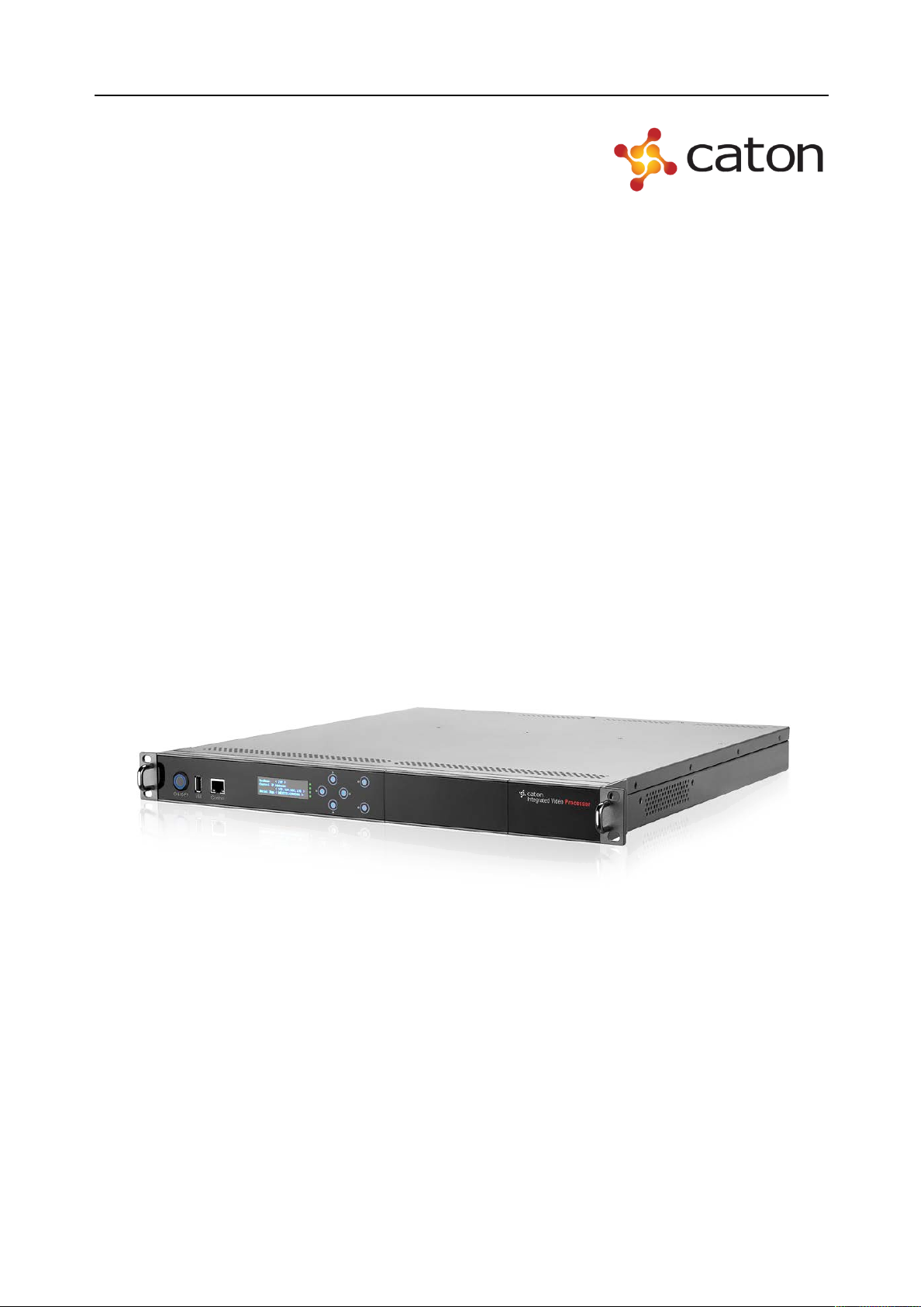
IVP-3000 Series
Multi-channel HD/SD Encoder
REFERENCE GUIDE
Page 2

Revision History
Issues of this Reference Guide are listed below:
Version Date Mainboard Version Comments
V1.1.0 15/02/2016 V2.4.2.1000 Updated to Version 2.4.2.1000
Page 3

Contents
Contents
Chapter 1 Introduction ................................................................................................................. 6
1.1 Introduction ....................................................................................................................... 6
1.2 Front Panel ........................................................................................................................ 7
1.2.1 Power...................................................................................................................... 7
1.2.2 USB Port ................................................................................................................ 7
1.2.3 Control port ............................................................................................................ 7
1.2.4 Main Display .......................................................................................................... 7
1.2.5 Indicator Lights ...................................................................................................... 7
1.2.6 Keypad ................................................................................................................... 8
1.3 Rear Panel ......................................................................................................................... 8
Chapter 2 Installing the Equipment ............................................................................................ 9
2.1 Read This First! ................................................................................................................. 9
2.2 Mounting and Ventilation .................................................................................................. 9
2.2.1 Fixing and Rack Mounting..................................................................................... 9
2.2.2 Ventilation .............................................................................................................. 9
2.3 Module Introduction........................................................................................................ 10
Chapter 3 Getting Started .......................................................................................................... 12
3.1 Introduction ..................................................................................................................... 12
3.2 How to Connect Up the Unit ........................................................................................... 12
3.3 How to Power Up the Unit .............................................................................................. 13
3.4 How to Set the Unit IP Address ...................................................................................... 13
Chapter 4 Front Panel Control .................................................................................................. 15
4.1 Introduction ..................................................................................................................... 15
4.2 Using the Front Panel Controls ....................................................................................... 15
4.2.1 Keyboard Lock ..................................................................................................... 15
4.2.2 Power up............................................................................................................... 15
Page 4

Contents
4.3 Basic Operation Logic ..................................................................................................... 16
4.4 IP Settings ....................................................................................................................... 17
4.5 HD Digital Encoder Module (HDE-420) ........................................................................ 18
4.6 SD Digital/Analog Encoder Module (SDE-420) ............................................................ 21
4.7 IPASI Output I/O Module (IO-ASI-O) ........................................................................... 24
4.8 ASI I/O Module (IO-ASI) ............................................................................................... 25
4.8.1 ASI In Setting ....................................................................................................... 25
4.8.2 ASI Out Setting .................................................................................................... 25
Chapter 5 Web Control ............................................................................................................... 26
5.1 Using the Web Graphical User Interface ......................................................................... 26
5.2 Web browser configuration ............................................................................................. 26
5.3 IVP-3000 Frame Setting ................................................................................................. 27
5.3.1 Account ................................................................................................................ 27
5.3.2 Network ................................................................................................................ 28
5.3.3 Date & Time ......................................................................................................... 29
5.3.4 Update &Reboot................................................................................................... 29
5.3.5 Device Information .............................................................................................. 33
5.4 Input Setting .................................................................................................................... 34
5.4.1 HD Digital Encoder Module (HDE-420/422) ...................................................... 34
5.4.2 SD Digital/Analog Encoder Module (SDE-420) ................................................. 43
5.4.3 Multi-stream HD Digital Encoder Module (MHDE-420) ................................... 51
5.4.4 ASI I/O Module (IO-ASI) .................................................................................... 59
5.5 TS Processor Setting ....................................................................................................... 60
5.6 R2TP Processor Setting ................................................................................................... 64
5.6.1 Stream Port Setting .............................................................................................. 64
5.6.2 Transport Streams Setting .................................................................................... 65
5.6.3 Ping Tools ............................................................................................................. 70
5.6.4 Software Upgrade................................................................................................. 71
5.7 Output Setting ................................................................................................................. 72
Page 5

Contents
5.7.1 IPASI Output I/O Module (IO-IPASI-O) ............................................................. 72
5.7.2 ASI I/O Module .................................................................................................... 75
5.8 Alarm ............................................................................................................................... 76
Annex A - Specifications ............................................................................................................. 77
Page 6

Introduction
Chapter 1 Introduction
1.1 Introduction
IVP-3000 is a broadcasting level multimedia processing platform. It adopts 1RU and a modular
design with 6 slots in it. By installing different modules, it could realize the following various
applications: satellite signals receiving, H.264/MPEG-2 HD/SD video encoding and decoding,
CA or BISS descrambling, real-time transmission stream monitoring, program multiplexing,
channel backup, etc.
The IVP platform is based on CPCI architecture with power redundancy design and hot swapping
functions. If one function module is out of order, the users only need to replace the corresponding
function cards, the whole process no need to cut off the power, and other function modules will
not be affected.
The IVP-3000 Series Multi-channel HD/SD Encoder is based on IVP platform, adopting H.264
HD encoding module, H.264/MPEG-2 SD encoding module, ASI I/O module and IP I/O module,
to achieve a multi-channel HD encoder with high flexibility, high density, high performance, high
scalability and high reliability.
The following is a summary of the features of IVP-3000 Series Multi-channel HD/SD Encoder:
(1) High Level Performance
Support H.264/MPEG-2 HD/SD encoding
Support H.264 4:2:2 / 4:2:0 chroma encoding
Support ASI redundant output
Support IP redundant output to different target IP address
Support 2 encoding latency mode:
Standard latency: 730ms
Low latency: 120ms
(2) High Density
Up to 5 channel HD encoding
Up to 10 channel SD encoding
Page 7

Introduction
HD encoder support 4 channel stereo audio encoding
(3) High Scalability
Modular design with various modules, it could be configured with different module
based on needs
Upgrade through simply adding or replacing with new module to save the upgrading
cost
1.2 Front Panel
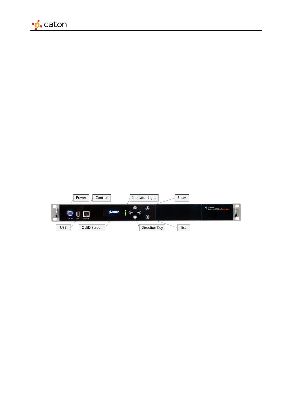
The front panel of the unit consists of a power, an USB Port, an Ethernet Control port, a main
OLED display screen, four Indicator Lights and six touch buttons.
Figure 1.1 Front Panel
1.2.1 Power
The ON/OFF button, after the device powered, press this button to start the device.
1.2.2 USB Port
Mount USB flash disk to save or apply the configuration file for disaster recovery.
1.2.3 Control port
Ethernet control port for web control.
1.2.4 Main Display
Control and status information is displayed on an OLED display.
1.2.5 Indicator Lights
Front panel LEDs indicate system status (Top->Bottom):
LED1.Power1 status: Green:OK; Red:Error;
Page 8

Introduction
LED2.Power2 status: Green:OK; Red:Error;
LED3.Temprature: Green:OK; Red:Over 50℃;
LED4.Alarm:Green:No unread error messages;Red:Error encountered;
1.2.6 Keypad
Include up, down, left and right direction keys, as well as “Enter” and “Esc” button.
1.3 Rear Panel
According to the power type of IVP-3000, the rear panel of IVP-3000 includes 2 types:
1) Chassis-R-H (Hot-Swap Redundancy Power)
Figure 1.2 Chassis-R-H Rear Panel
The Chassis-R-H rear panel consists of six slots (U1, U2, U3, L1, L2 and L3), 2 hot-plug power.
You can insert different modules according to user needs.
2) Chassis-R (Internal Dual Redundancy Power)
Figure 1.3 Chassis-R Rear Panel
The Chassis-R rear panel of the unit consists of six slots (U1, U2, U3, L1, L2 and L3), Power
Interface, Power Switch and Fan.
You can insert different modules according to user needs.
Note: Keep the vent clear to ensure the rejection of heat.
Page 9

Installing the Equipment
Chapter 2 Installing the Equipment
2.1 Read This First!
This Reference Guide is written for operators / users of the IVP-3000. It describes the unit’s
functions and operation. The Reference Guide is written to assist in the installation and
day-to-day operation and care of the unit. Maintenance information requiring the covers to be
removed is not included.
2.2 Mounting and Ventilation
2.2.1 Fixing and Rack Mounting
The equipment is designed for fixed use only and has been shipped with fixing brackets suitable
for a standard 19-inch rack. When installed in a rack, it should be secured using the fixing
brackets. In addition, support shelves must be used to reduce the weight on the brackets. Ensure it
is firmly and safely located and it has an adequate free-flow of air.
Slide the unit onto the chassis supports and affix to the rack by means of an M6 x 18 mm panhead
screw in each corner.
A freestanding unit should be installed on a secure horizontal surface where it is unlikely to be
knocked or its connectors and leads disturbed.
2.2.2 Ventilation
Side openings in the unit, as well as rear-mounted cooling fans, are provided for ventilation. They
ensure reliable operation of the product and protect it from overheating. The openings of the fans
must not be blocked or covered.
Page 10
Installing the Equipment
2.3 Module Introduction
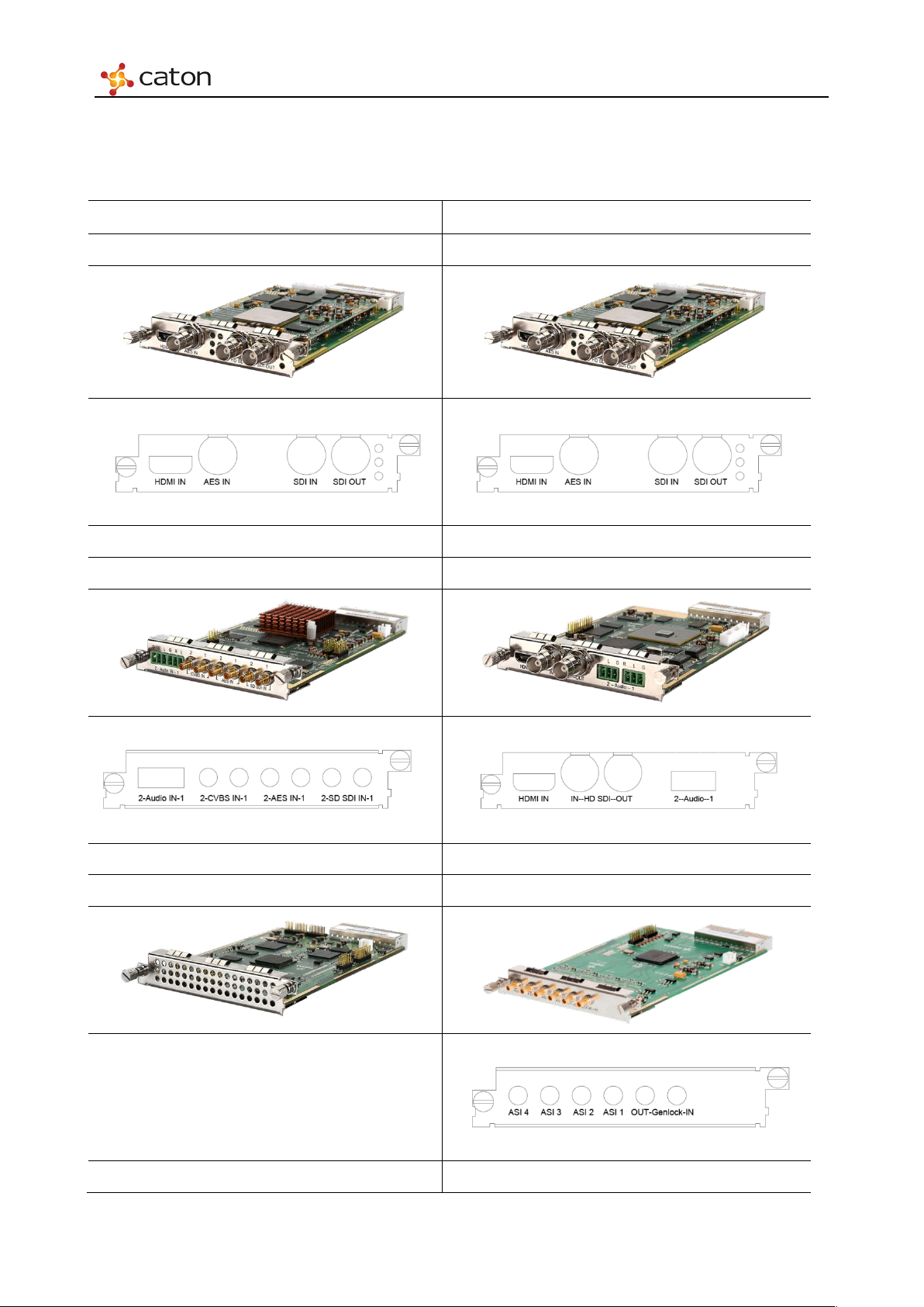
The introduction of encoding module listed in the following tables.
422 HD Digital Encoder Module (HDE-422) 420 HD Digital Encoder Module (HDE-420)
Function: 1 channel HD/SD 4:2:2/4:2:0 H.264 encoding Function: 1 channel HD/SD 4:2:0 H.264 encoding
Interface:
Interface:
SD Digital/Analog Encoder Module (SDE-420) Multi-Stream HD Digital Encoder Module (MHDE-420)
Function: 2 channel SD H.264/MPEG-2 encoding Function:1 channel HD encoding, 3 encoding stream output
Interface:
Interface:
Multi-Channel H.264 Transcoder Module (MHDT-420) ASI I/O Module (IO-ASI)
Function: Multi-stream H.264 HD/SD transcoding Function: 4 ASI input or output, support various pattern
Interface:
IPASI Output I/O Module (IO-IPASI-O) Multi-Protocol IP Transmitting Module (SMIP)
Page 11

Installing the Equipment
Function: Support IP output and 2 ASI output Function: Multi-Protocol IP Transmitting over Open Internet
Interface:
Interface:
Page 12
Getting Started
Chapter 3 Getting Started
3.1 Introduction
Due to the number of different ways the IVP-3000 Series can be used, it is impossible to give
precise setting up instructions for every possible working scenario. This chapter, therefore, gives
general guidance and principles on how to power up and set up your unit for operation and
describes the more common operations you will want to perform.
For details of all Front Panel menus and controls, see Chapter 4, Front Panel Control. For details
of all Web Graphical User Interface menus and controls, see Chapter 5, Web Control.
3.2 How to Connect Up the Unit
See Chapter 2, installing the Equipment for all connector details.
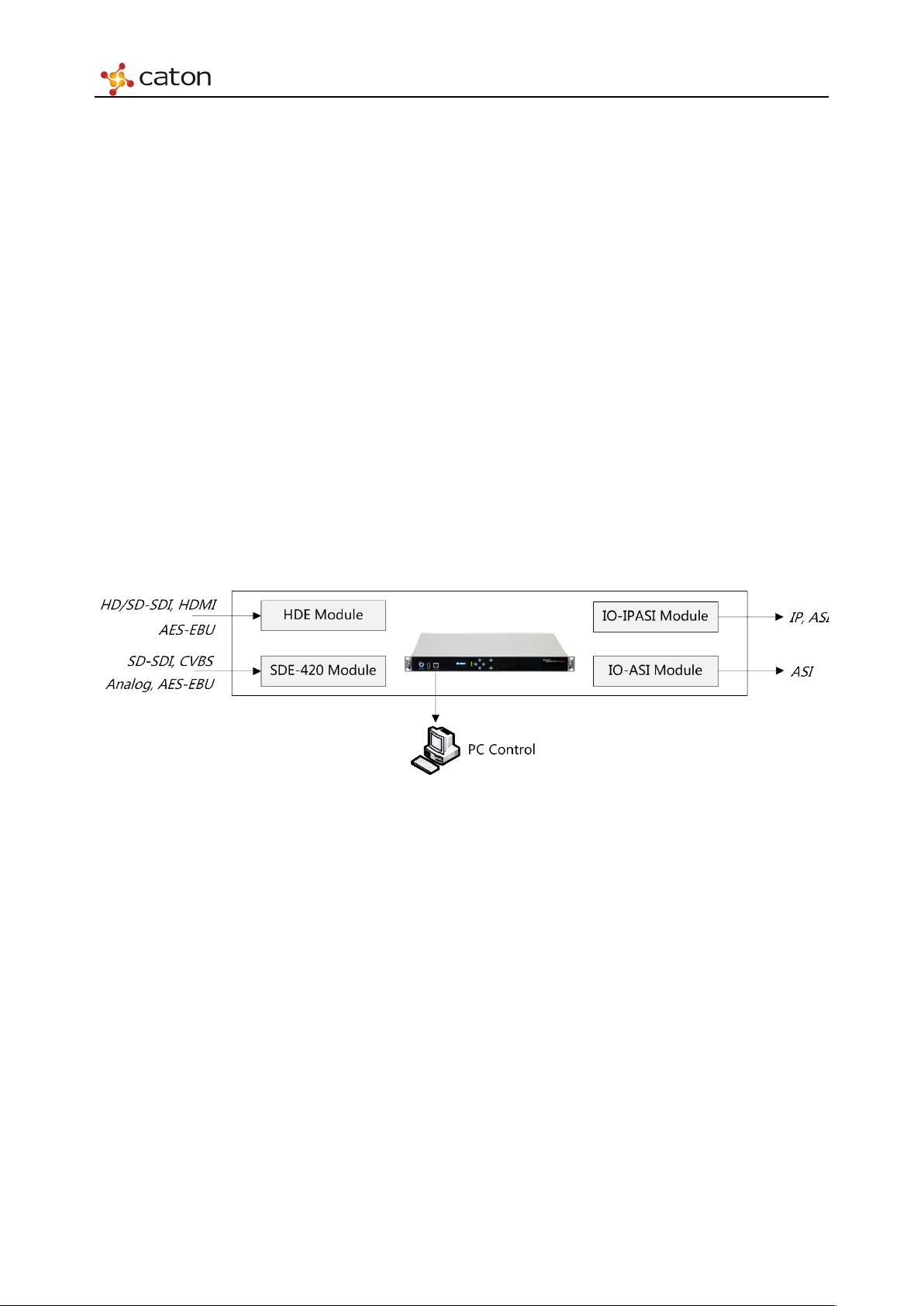
Figure 3.1 Equipment Connection Diagram
To connect up the unit(s):
Connect signal input connectors (for your input Transport Streams) to your local area network if
IP/ASI inputs are to be used.
Connect signal output connectors (for your output Transport Streams) to your local area network
if IP/ASI outputs are to be used.
Connect computer control connectors Web Control to your local area network. Both connectors
are in the same subnet mask.
Connect single or dual AC power connectors, depending on the option purchased, to the power
supply.
Connect your signal cables to/from your option cards, depending on which options are fitted to
Page 13

Getting Started
your unit, as required.
3.3 How to Power Up the Unit
To power up the unit(s):
With all signal and power cables connected as required, through equipment power supply. Wai t
for unit to initialize completely.
3.4 How to Set the Unit IP Address
Setting the IP address of a unit is accomplished using the front panel menus. For a full description
of these menus, see Chapter 4, Front Panel Control.
To set the IP address of the unit(s):
1. Ensure the unit is fully powered up.
2. On the OLED front panel, using the touch button, go to the IVP-3000 Frame>IP Setting
option.
3. Press Enter Button to select.
4. Using the touch button, set the IP address, subnet mask and gateway address.
5. Press the Enter button to save or Esc to discard the changes.
Note:1. It may be necessary to set the IP address, gateway address and Virtual IP address to 0, and to set
a subnet mask in order to allow the IP address to be changed.
2.IP Addresses on the unit must adhere to RFC3330 range of restrictions as listed in the following
table of allocated IP addresses.
3.Make sure that the control network and data networks do not conflict.
3.5 How to Configure Ethernet Control Port
The Base Chassis has control port that support IEEE 802.3 100 BaseTX and 1000 BaseT
protocols.
Figure 3.2 Control Port
Page 14

Getting Started
The Ethernet control ports are used to connect the unit to a control computer for control through a
web browser.
Ethernet Control Port Parameters
A single IP port is defined for all Ethernet control traffic to and from the chassis. The physical
ports used for Ethernet control are by default the control Ethernet ports. The control ports can
raise an alarm during abnormal operational conditions.
Page 15
Front Panel Control
Chapter 4 Front Panel Control
4.1 Introduction
This chapter describes the features and options provided by the Front Panel menus for controlling
the IVP-3000.
Note: After powering up (see Chapter 3, Getting Started), wait for initialization to complete
(approximately 2 minutes, depending on the number of options fitted in the chassis)before
attempting to use the front panel menus and controls.
4.2 Using the Front Panel Controls
The front panel of the unit consists of a power, an USB Port, an Ethernet Control port, a main
OLED display screen, four Indicator Lights and six touch buttons.
The unit can be controlled through the front touch buttons.
Figure 4.1 IVP-3000 Front Panel
4.2.1 Keyboard Lock
The controls are locked after a time of inactivity. The keys can be unlocked by click “▲”,“◄ ”,
“▼ ” ,“ ► ” in turn, then in this sequence as instructed “Unlocked”on the front panel.
4.2.2 Power up
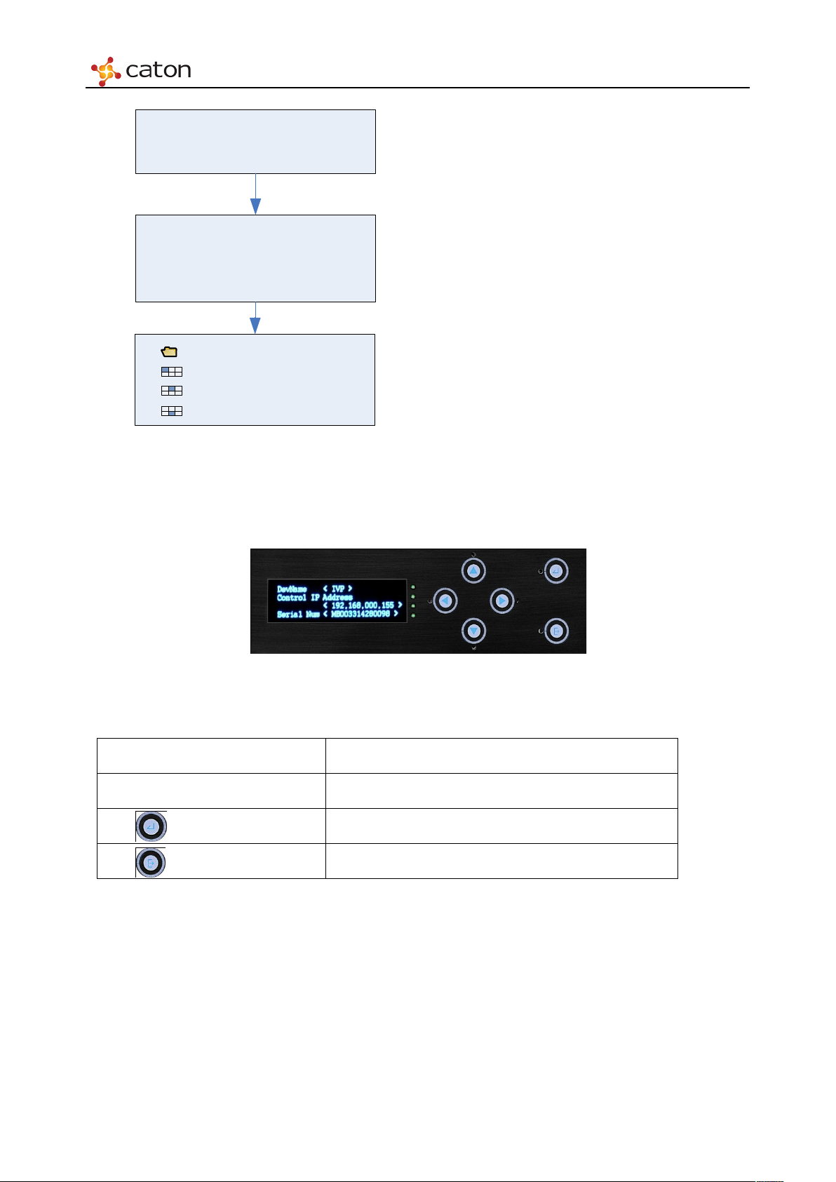
Power up IVP-3000, OLED screen will display as follows:
Page 16
Front Panel Control
▶
IVP Frame
Input
_U
1_
HD Enc
Input
_
U2
_SD Enc
Output_L2_IP_ASI
IVP
Starting
0
%
Dev Name < IVP
>
Control IP Address
<192.168.
000.
159
>
Serial Num <
10001
>
Power on the device
,
the screen
displays company logo
.
After about 60
s,
the screen displays
device status
After c
lick “
Enter”
button, the screen
displays device setting tree.
Figure 4.2 Booting Front Panel Display Process
4.3 Basic Operation Logic
Figure 4.3 Front Panel Display
There are 6 buttons on the front panel.
“▲”,“▼ ”
“►”,“◄ ”
“Enter” button Enter editable mode or navigate to a sub menu.
“ESC” button Exit editable mode or go back to a parent menu.
Users may need to unlock the front panel, and then refer to the menu structure of the front panel
Select parameters to watch or configure.
Adjust configurable values in editable mode.
display, with the button to complete the device parameter settings, parameter queries and other
operations.
Page 17
Front Panel Control
Local IP
<Custom>
Gateway
<Custom>
4.4 IP Settings
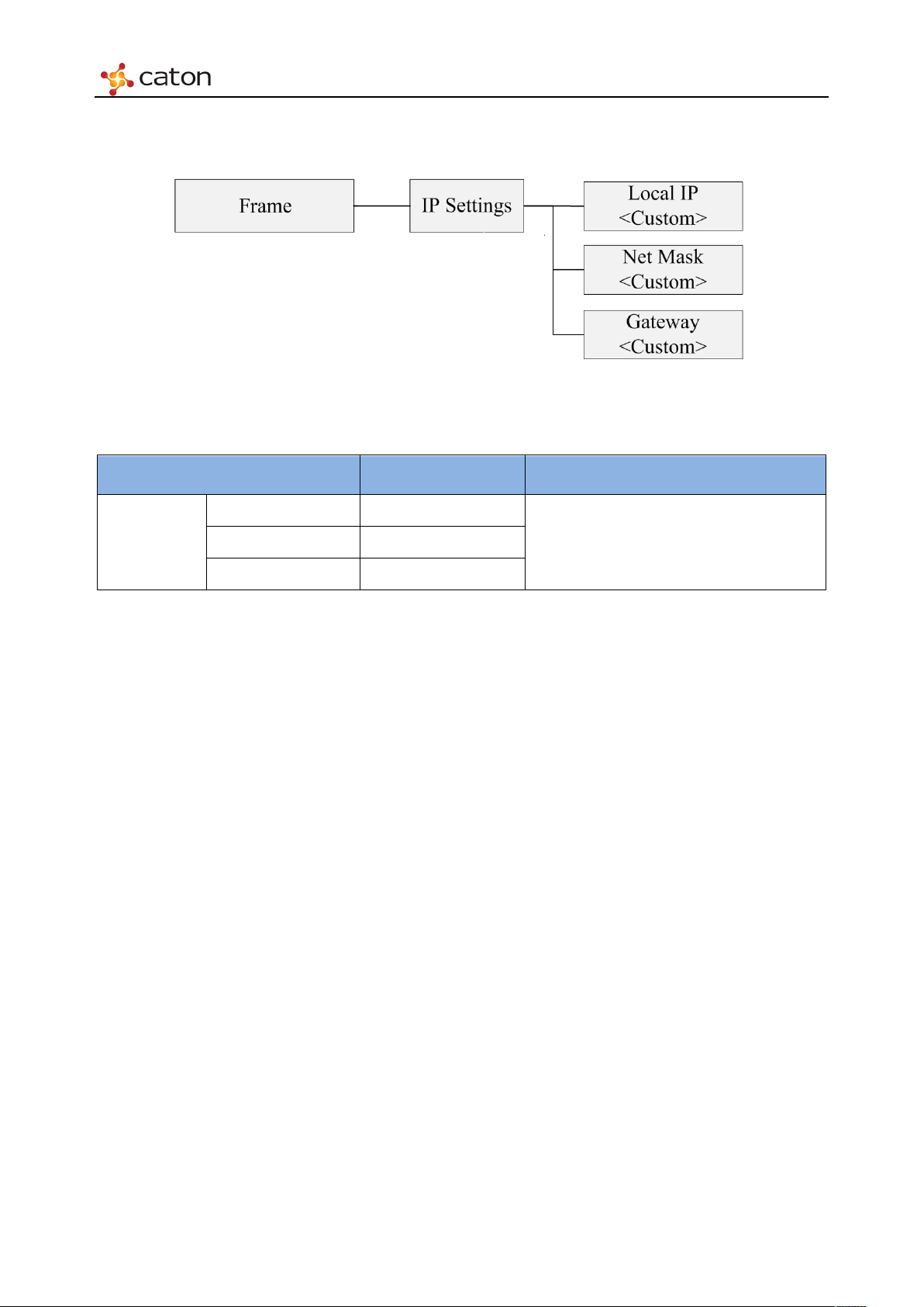
Figure 4.4 IP Settings
Ta bl e 4.1 IP Settings
Item Option Comment
Frame
IP Setting
IP Settings of Device Control Port. Net Mask <Custom>
Page 18

Front Panel Control
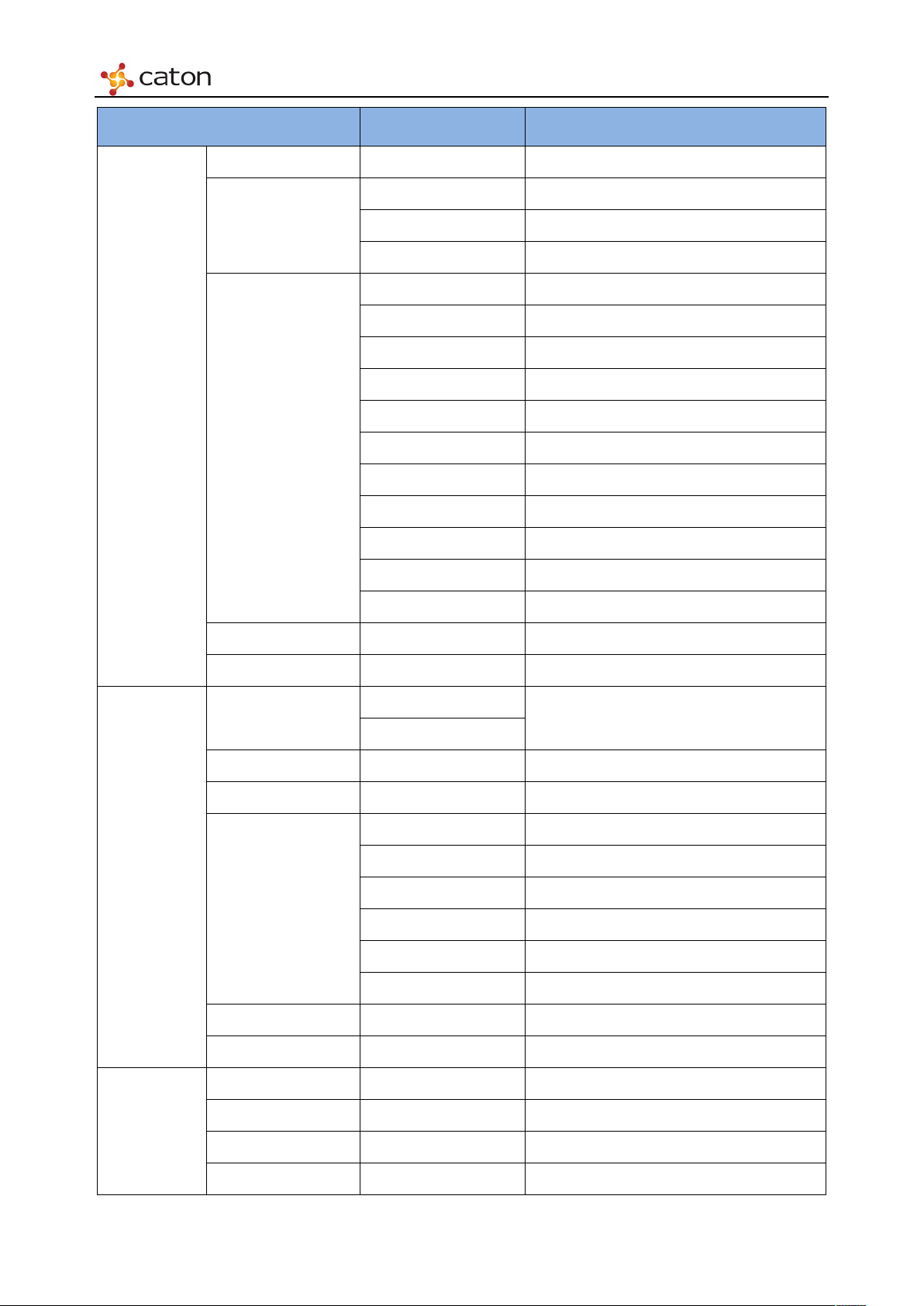
4.5 HD Digital Encoder Module (HDE-420)
Figure 4.5 HDE-420 Settings
Ta bl e 4.2 HDE-420 Settings
Page 19
Front Panel Control
Item Option Comment
Encode Mode <H.264>
SDI
Vid eo
Settings
Video Source
HDMI
CBar Color Bar
1080p30
1080p29.97
1080p25
1080i59.94
1080i60
Video Format
1080i50
720p59.94
720p60
720p50
480i59.94
576i50
Video Bitrate <Custom> 500-60000 (Kbps)
Video PID <Custom>
Audio
Settings
Program
Settings
Enable
Audio Enable
Enable current audio channel
Disable
Audio Source ——
Audio Format <MPEG1>
96
128
192
Audio Bitrate
256
320
384
Audio PID <Custom>
Audio Mode <Stereo>
TS ID <Custom> 0x0 to 0xFFFF
PCR PID <Custom> 0x20 to 0x1FFE
PMT PID <Custom> 0x20 to 0x1FFE
Service ID <Custom> 0x0 to 0xFFFF
Page 20

Front Panel Control
TS Bitrate
<Custom>
500~65000 (Kbps)
Input Source
<Read Only>
Service Name ——
Status <Read Only>
Status
Input Format <Read Only>
Page 21
Front Panel Control
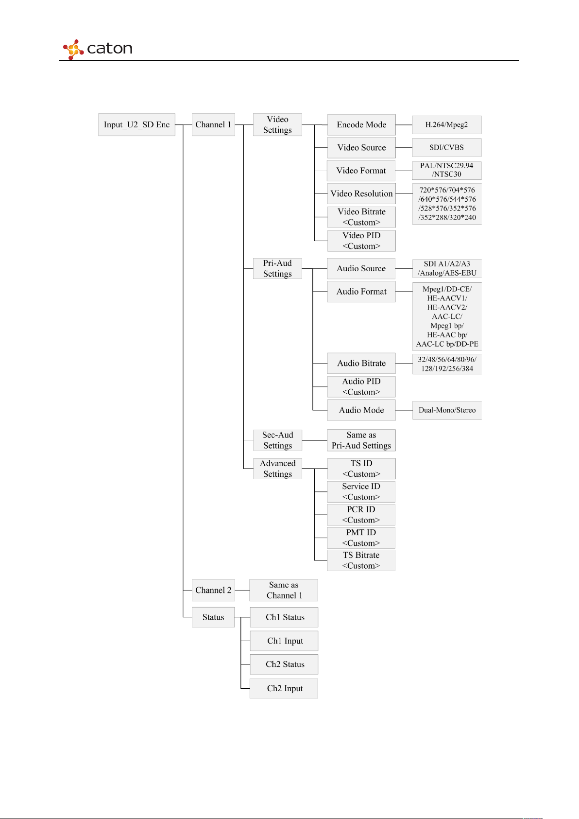
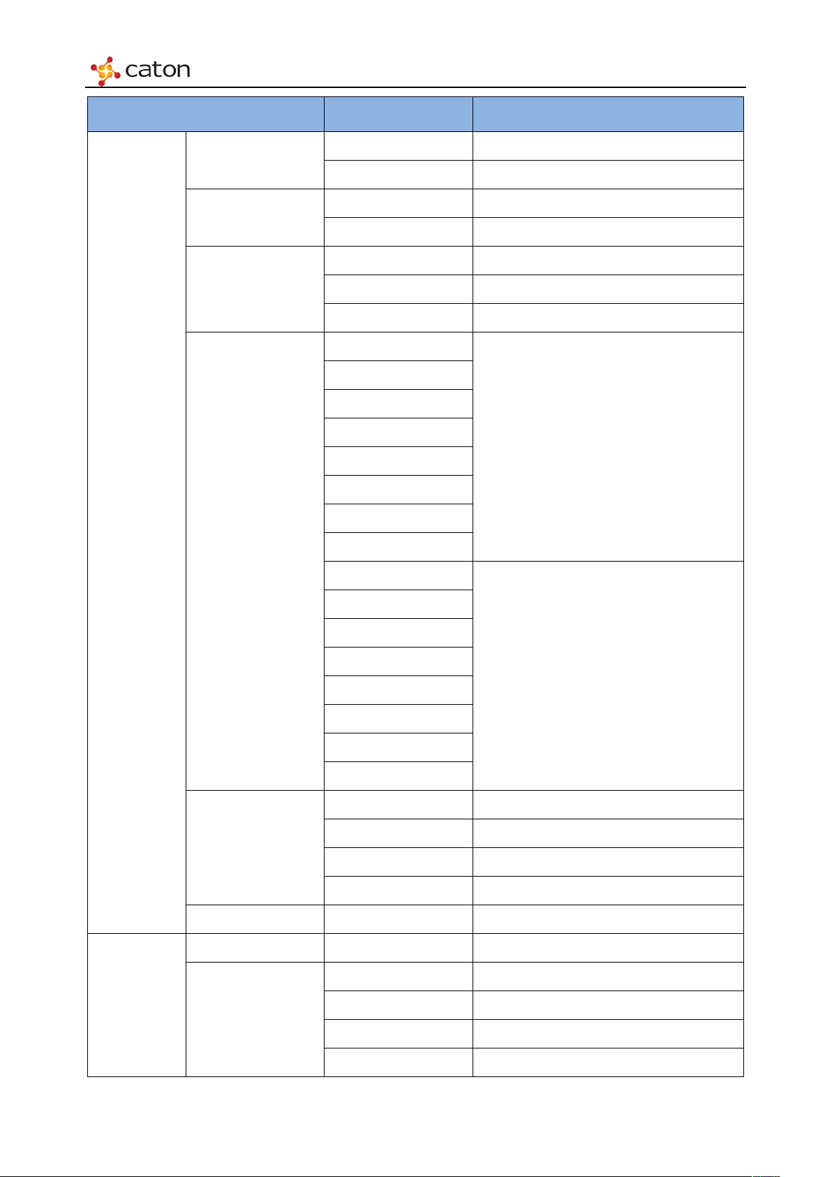
4.6 SD Digital/Analog Encoder Module (SDE-420)
Figure 4.6 SDE-420 Settings
Ta bl e 4.3 SDE-420 Settings
Page 22
Front Panel Control
Item Option Comment
H.264
Encode Mode
MPEG2
SDI
Video Source
CVBS
PAL
Vid eo
Settings
Video Format
Video Resolution
NTSC/29.97
NTSC/30
720*576
704*576
640*576
544*576
PA L
528*576
352*576
352*288
320*240
720*480
704*480
640*480
544*480
NTSC
528*480
Audio
Settings
352*480
352*288
320*240
250~6000 H.264 Single-Channel
250~15000 H.264 Twin-Channel
Video Bitrate
500~7000 MPEG-2 Single-Channel
500~15000 MPEG-2 Twin-Channel
Video PID <Custom>
Audio Source Enable Enable current audio channel
MPEG-1 Layer II
AAC-LC
Audio Format
HE-AAC V1
HE-AAC V2
Page 23

Front Panel Control
32
64
96
128
192
320
448
576
Audio PID
<Custom>
Stereo
Service ID
<Custom>
0x0 to 0xFFFF
PMT PID
<Custom>
0x20 to 0x1FFE
Ch1 Status
<Read Only>
Ch2 Status
<Read Only>
AC3 Bypass
48
80
112
160
Audio Bitrate
224
384
Program
Settings
Status
512
640
Dual-Mono
Audio Mode
TS ID <Custom> 0x0 to 0xFFFF
PCR PID <Custom> 0x20 to 0x1FFE
TS Bitrate <Custom> 500~20000 (Kbps)
Ch1 Input <Read Only>
Ch2 Input <Read Only>
Page 24

Front Panel Control
ON
Dest IP
<Custom>
Destination IP address
UDP
Ser List
——
Service ID to output
ASI Out
——
——
Select the Source to output
Speed
<Read Only>
4.7 IPASI Output I/O Module (IO-ASI-O)
Stream
Channel
Status
Figure 4.7 IO-IPASI-O Settings
Ta bl e 4.4 IO-IPASI-O Settings
Item Option Comment
Enable
OFF
Dest Port <Custom> Destination IP port
Enable using the current Ethernet port
Protocol
RTP
Bitrate <Custom> Greater than the bitrate of selected service
Status <Read Only>
Tra nsport P rotocol
Page 25
Front Panel Control
ASI 1 IN
<Read Only>
Display status of ASI 1 input
ASI 1 OUT
——
Select the source to output
Duplex <Read Only>
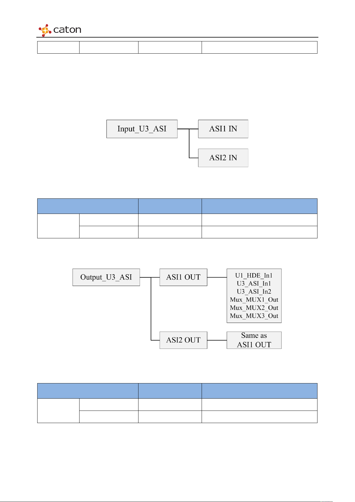
4.8 ASI I/O Module (IO-ASI)
4.8.1 ASI In Setting
Figure 4.8 IO-ASI Input Settings
Ta bl e 4.5 IO-ASI Input Settings
Item Option Comment
Input ASI
ASI 2 IN <Read Only> Display status of ASI 2 input
4.8.2 ASI Out Setting
Figure 4.9 IO-ASI Output Settings
Ta bl e 4.6 IO-ASI Output Settings
Input ASI
Item Option Comment
ASI 2 OUT —— Select the source to output
Page 26
Web Control
Chapter 5 Web Control
5.1 Using the Web Graphical User Interface
The IVP-3000 is designed to be configured and controlled by its own web graphical user
interface.
The Graphical User Interface uses widget based architecture. This section describes the functions
and elements.
5.2 Web browser configuration
Use an Internet web browser running on a personal computer (PC) to take advantage of the
remote setup capability. Below is the guide you need to follow:
Prepare a computer with Internet web browser.
Tips: IE version 8.0 or above Firefox version 6.0.2 or above are highly recommended.
Connect your PC to the management network interface of the device via Ethernet.
Confirm computer IP address, make sure that the device and the computer in the same
network segment
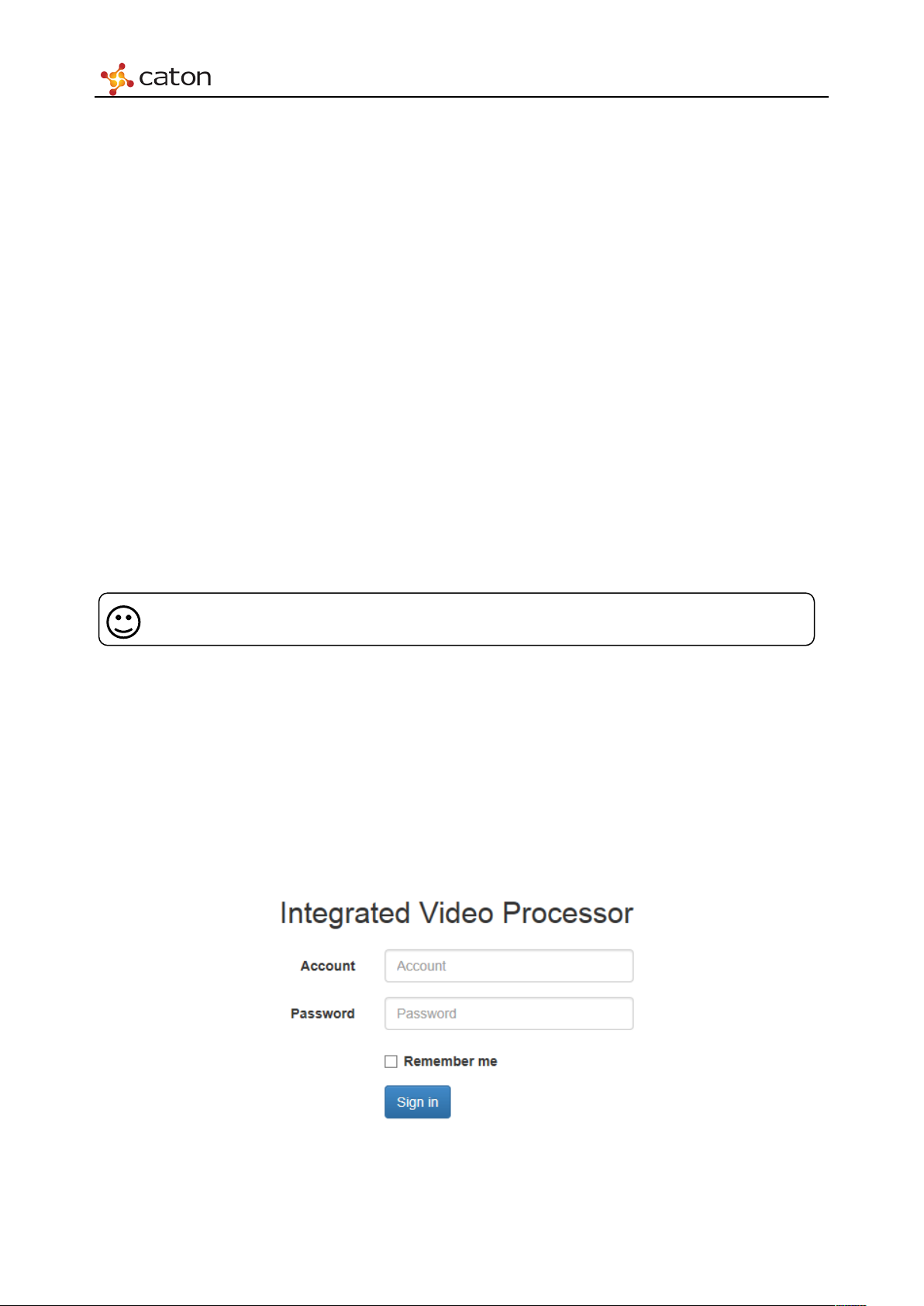
Input the device IP address in the web browser, it will displays the Login page, as follows:
Figure 5.1 Login
Page 27
Web Control
Type in the Account and Password to login.
(Default Account: admin Default Password: 123456)
5.3 IVP-3000 Frame Setting
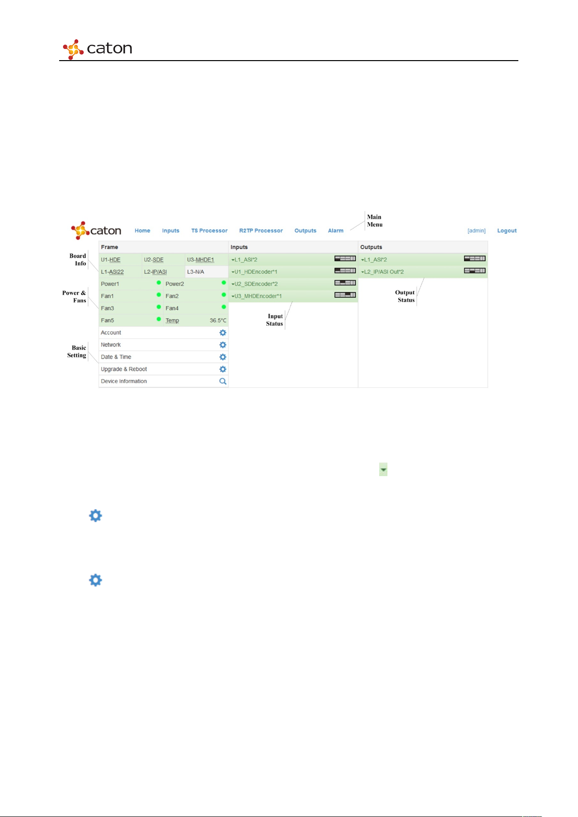
When users get a successful user authentication at the IVP-3000 login prompt, the Home page
appears as shown below.
Figure 5.2 Home
Home page displays the basic info of IVP-3000 device, including module, power, fan and
temperature. It also includes real-time input/output statistics. Click to view status information
of selected module.
Click in Basic Settings bar to configure the basic settings of IVP-3000 device.
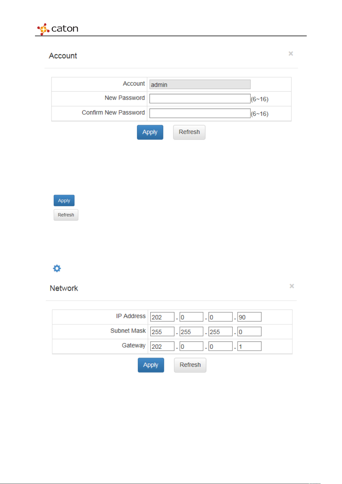
5.3.1 Account
Click in Account bar to modify the password to login.
Page 28
Web Control
Figure 5.3 Account
The password need to be in 6~16 characters (From A-Z, 0-9).
Click to save the configuration.
Click to refresh current page.
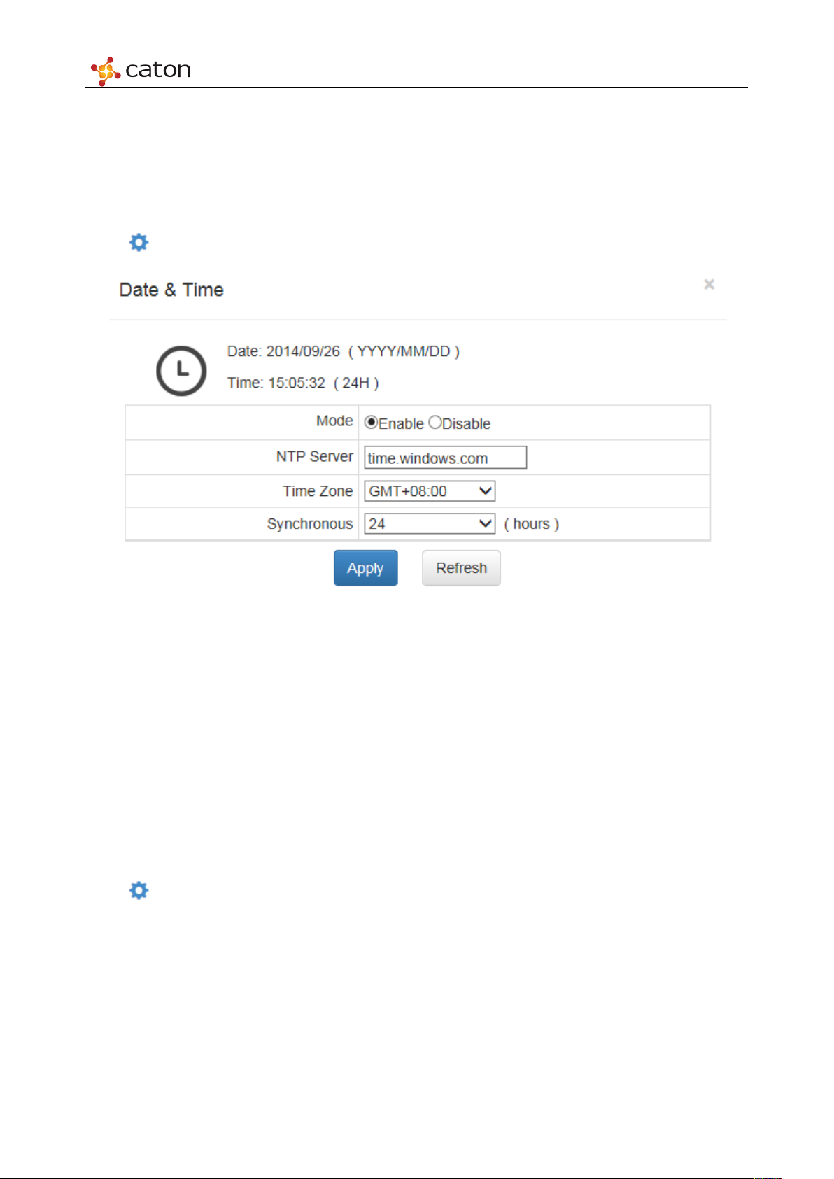
5.3.2 Network
Click in Network bar to configure the device IP address.
Figure 5.4 Network
IP Address: Device IP Address setting.
Subnet Mask: Net Mask setting.
Gateway: Default Gateway setting.
Page 29
Web Control
User can also configure device IP through panel control, please refer to Chapter 4 for more info.
5.3.3 Date & Time
Click in Date & Time bar to configure the date and time info of the device.
Figure 5.5 Date & Time
Mode: Enable/Disable
NTP Server: Net Mask setting.
Time Zone: Default Gateway setting.
Synchronous: The cycle used to synchronous with NTP server
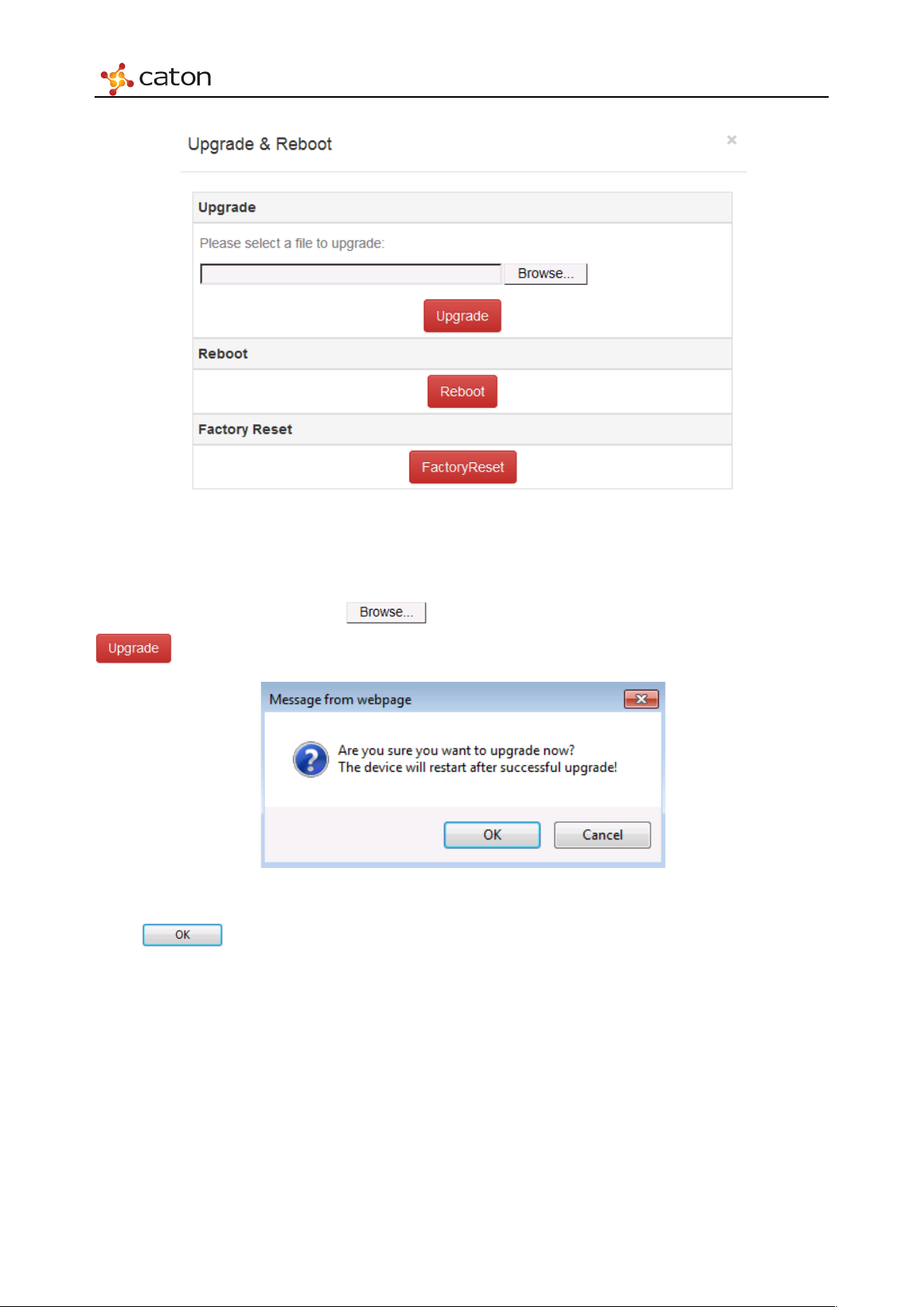
5.3.4 Update &Reboot
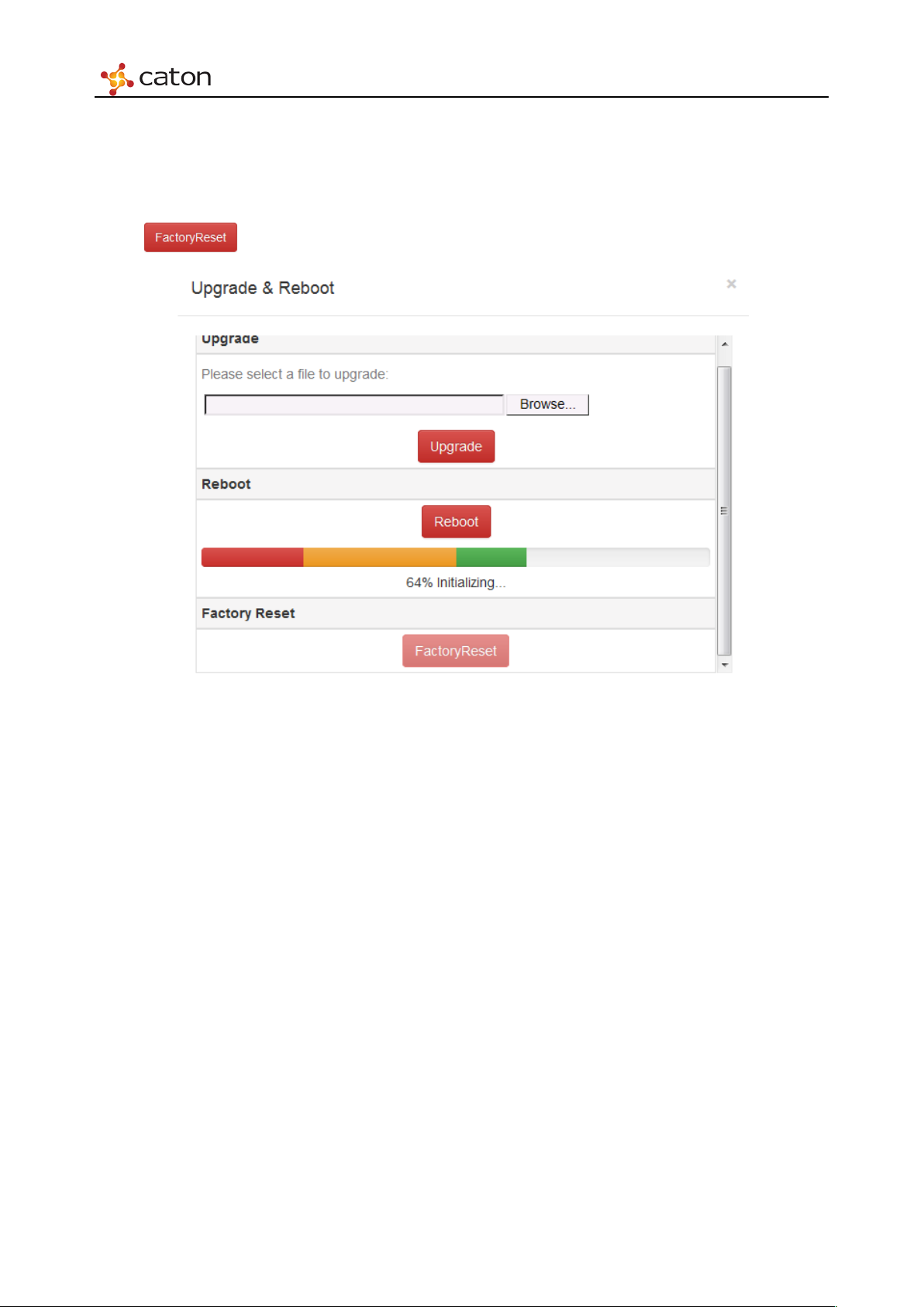
Click in Update & Reboot bar to update the main board or reboot the device. You may need
to input the password again for verification.
Page 30
Web Control
Figure 5.6 Update & Reboot
1. Upgrade
To upgrade the main board, click to select the upgrade package in PC and click
to submit it.
Figure 5.7 Confirm
Click to confirm the upgrade.
Page 31
Web Control
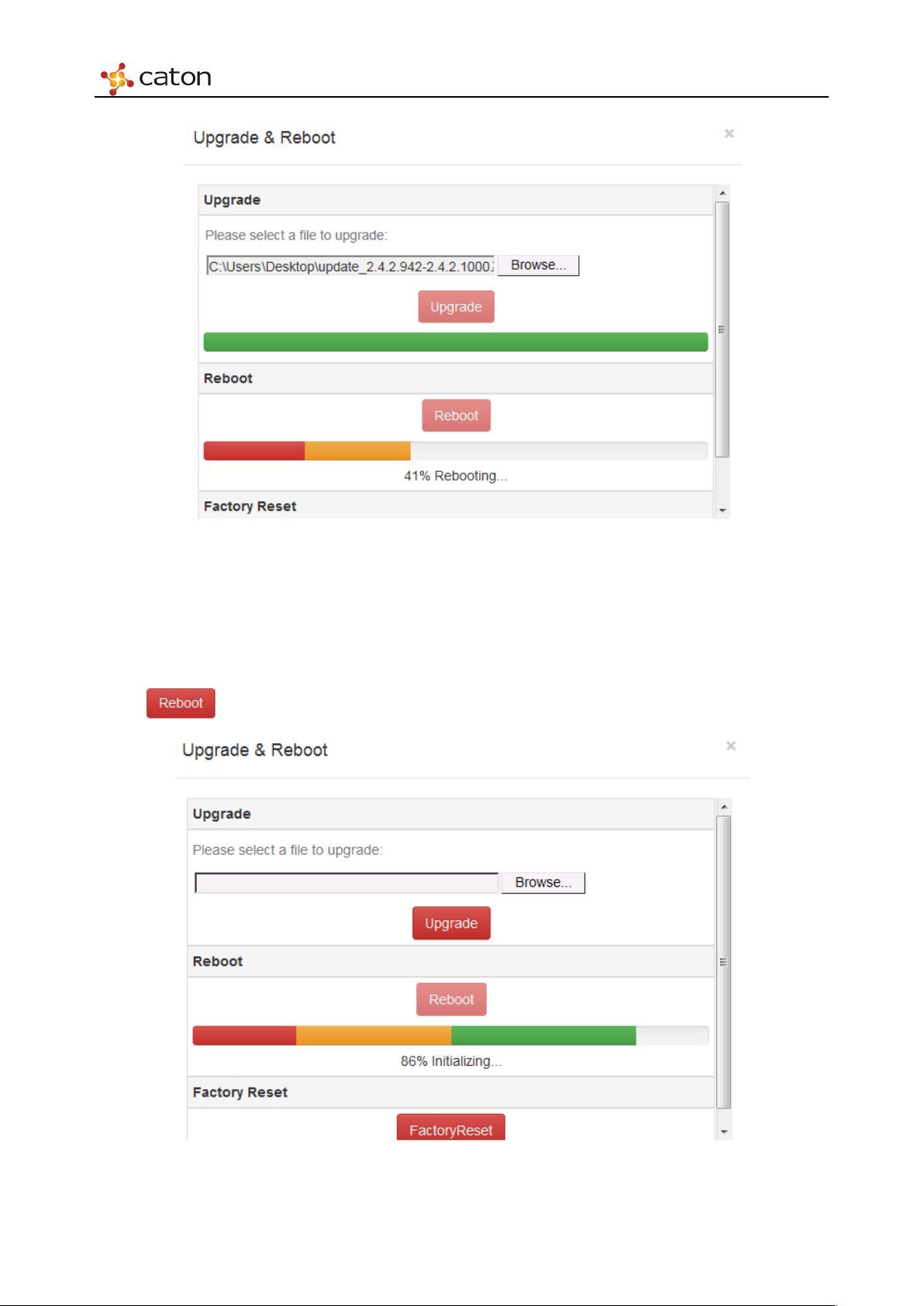
Figure 5.8 Upgrade
The upgrade will take about 5 minutes, please do not leave this page or power off. After the
upgrade is finished, web will refresh automatically.
2. Reboot
Click to reboot the device.
Figure 5.9 Reboot
Page 32
Web Control
The reboot will take about 3 minutes, please do not leave this page or power off. After the reboot
is finished, web will refresh automatically.
3. Factory Reset
Click to recover to the default settings.
Figure 5.10 Factory Reset
The reset will take about 5 minutes, please do not leave this page or power off. After the reset is
finished, web will refresh automatically.
Page 33
Web Control
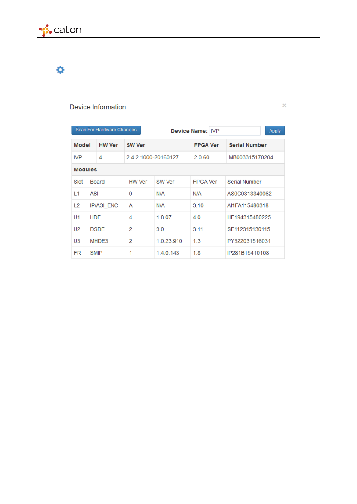
5.3.5 Device Information
Click in Device Information bar to view the basic info of device and modules, including
Hardware Version(HW), Software Version(SW), FPGA Version, Serial Number etc.
Figure 5.11 Device Information
Page 34
Web Control
5.4 Input Setting
Click Inputs in main menu to open the Input Setting page.
5.4.1 HD Digital Encoder Module (HDE-420/422)
Click in HD Low Encoder*1 bar to configure HDE-420 module.
Click in HD SL Encoder*1 bar to configure HDE-422 module.
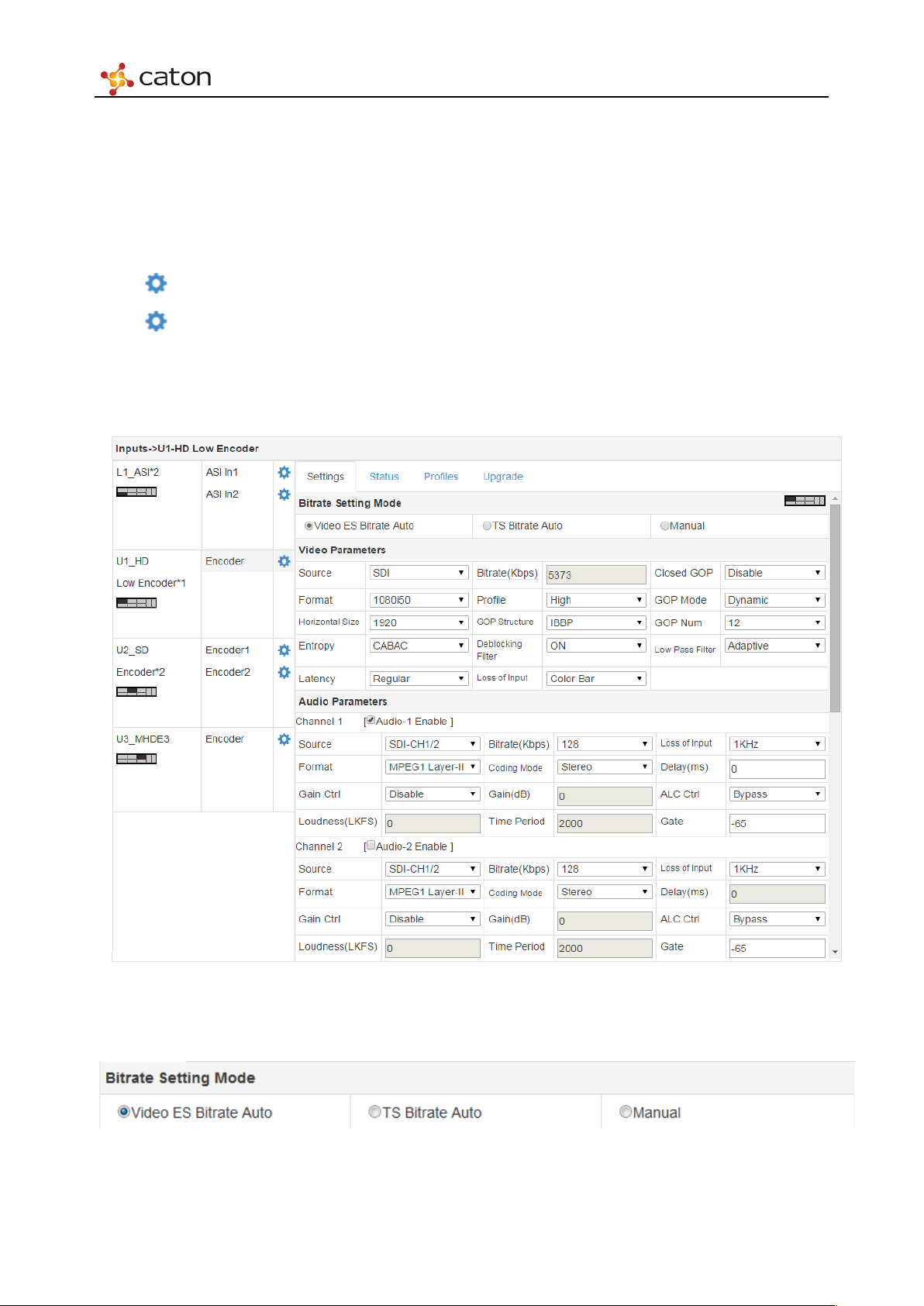
5.4.1.1 Settings
Select Settings column to configure basic encoding settings of HDE-420/422.
1. Bitrate Setting Mode
Figure 5.12 Setting
Figure 5.13 Bitrate Setting Mode
Page 35
Web Control
Video ES Bitrate Auto:
Video ES Bitrate cannot be editable and will be calculated automatically from TS Bitrate
TS Bitrate Auto:
TS Bitrate cannot be editable and will be calculated automatically from Video ES Bitrate
Manual:
Video ES Bitrate and TS Bitrate will be decided both by user.
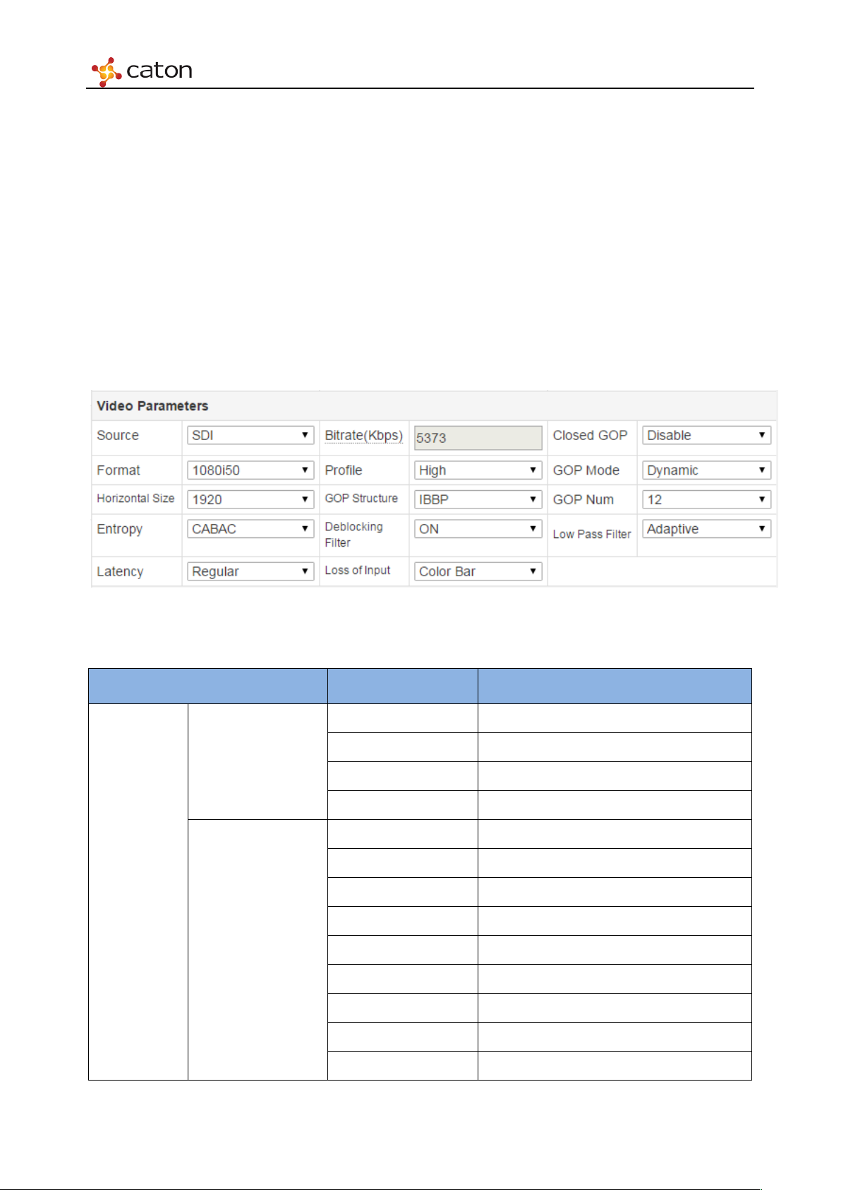
2. Video Parameters
Vid eo
Parameters
Figure 5.14 Video Parame ters
Ta bl e 5.1 Vid eo P ara meters
Item Option Comment
Color Bar Internal Signal
Black Field Internal Signal
Source
SDI External Signal
HDMI External Signal
Auto According to the input source format
1080p30
1080p29.97
1080p25
Format
1080i59.94
1080i60
1080i50
720p59.94
720p60
Page 36

Web Control
480i59.94
1920
1280
1280
848
720
480
CAVLC
Regular
Codec delay About 700ms
Super Low
Codec delay About 40ms(HDE-422 Only)
Main
High 4:2:2
HDE-422 Only
IBP
ON
Wit h TS output
None
No Video Encoding, With TS output
720p50
576i50
1440
1080p/1080i
960
960
Horizontal Size
720p
640
542
480i/576i
352
Entropy
CABAC
Latency
Low Delay Codec delay About 160ms
Bitrate(Kbps) 500-60000
Profile
High
IP
GOP Structure
IBBP
Deblocking Filter
OFF
Loss of Input
Automatically switch to ColorBar,
Color Bar
Automatically switch to Black Field,
Black Field
Wit h TS output
Page 37
Web Control
Enable
according to the scene
GOP Num
1~30
Unit frame
Adaptive
Moderate
No TS Output No TS output
Closed GOP
Disable
GOP Mode
Low Pass Filter
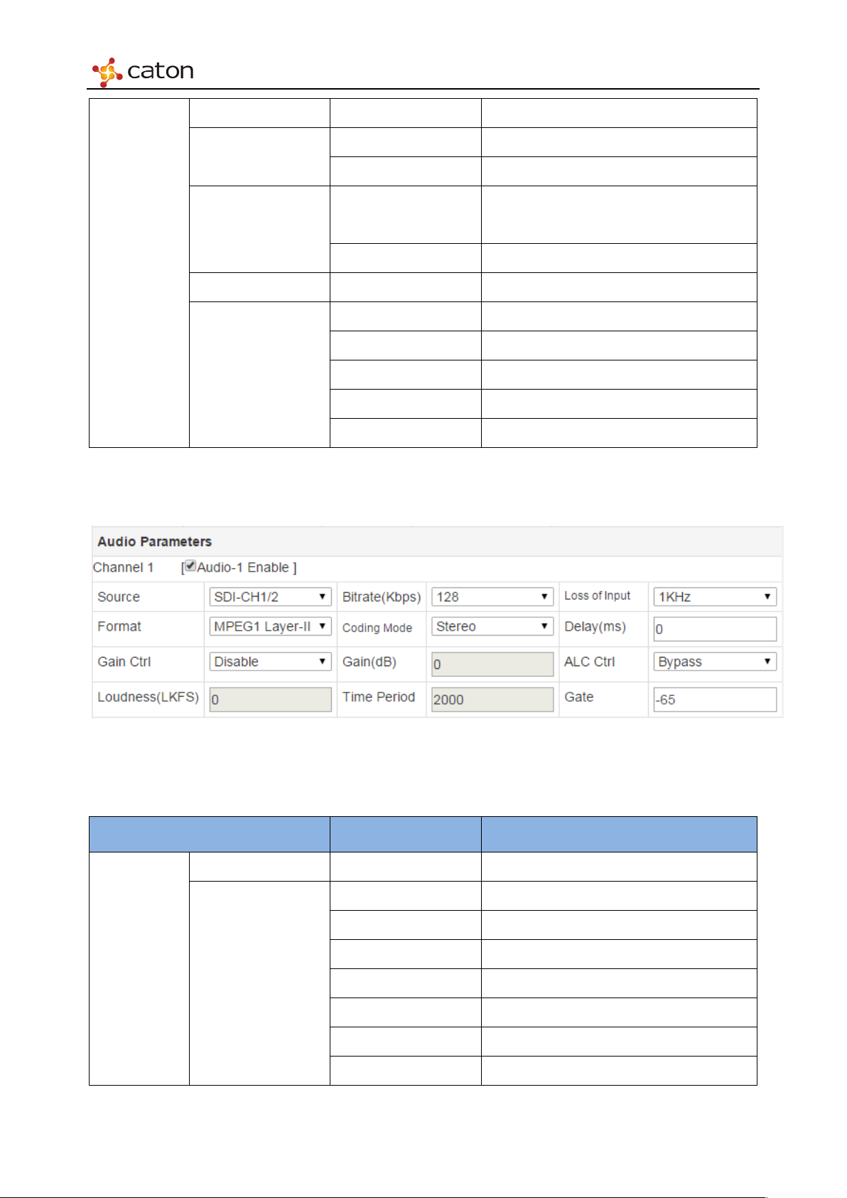
3. Audio Parameters
Dynamic
Automatically adjust the GOP length
Constant Constant GOP length
OFF
Weak
Strong
Audio
Parameters
Figure 5.15 Audio Parameters
Ta bl e5 .2 Audio Parameters
Item Option Comment
Audio-X Enable On/Off Click on to enable current audio channel
SDI-CH1/2
SDI-CH3/4
SDI-CH5/6
Source
SDI-CH7/8
HDMI-CH1/2
HDMI-CH3/4
HDMI-CH5/6
Page 38

Web Control
AES-EBU
MPEG1 Layer-II
96
192
320
Dual Mono
audiofor encoding
for encoding
Mute
Automatically switch to Mute audio
±500
Regular Latency Mode
±0
Super Low Latency Mode (HDE-422 only)
Enable
Enable Audio gain adjustment function
Gain(dB)
-20~+20
Audio gain value
Bypass
disable Audio ALC function
calculation
HDMI-CH7/8
1KHz
Format
AAC-LC
128
Bitrate(Kbps)
256
384
Stereo
Using The left channel data ofinput
Mono L
Coding Mode
Using The right channel data of input
Mono R
audiofor encoding
Mix the left channel and right channel data
Mono Mix
1KHz Automatically switch to 1KHz
Loss of Input
None No audio output
Delay(ms)
±100 Low Latency Mode
Disable Disable Audio gain adjustment function
Gain Ctrl
Loudness(LKFS) -30~0 Target loudness
Tim e Pe riod 200~5000ms Time window used to control loudness
ALC Ctrl
Gate -65~-40LKFS
Enable Enable Audio ALC function
Minimum threshold value of loudness
Page 39
Web Control
PMT PID
0x20 to 0x1FFE
Audio2 PID
0x20 to 0x1FFE
Service ID
0x0 to 0xFFFF
Audio2 PID
0x20 to 0x1FFE
PCR Interval
1~40ms
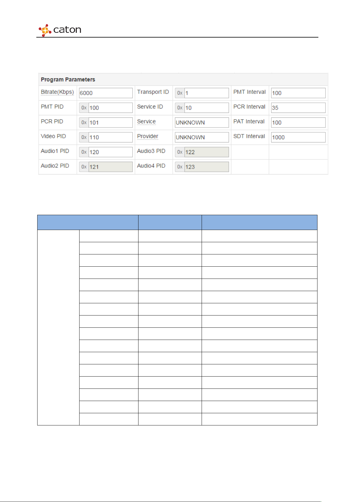
4. Program Parameters
Figure 5.16 Program Parameters
Ta bl e 5.3 Program Parameters
PSI/SI
Parameters
Item Option Comment
Bitrate(Kbps) 500~65000
PCR PID 0x20 to 0x1FFE
Video PID 0x20 to 0x1FFE
Audio1 PID 0x20 to 0x1FFE
Transport ID 0x0 to 0xFFFF
Service <Custom>
Provider <Custom>
Audio1 PID 0x20 to 0x1FFE
PMT Interval 1~500ms
PAT Interval 1~500ms
SDT Interval 1~10000ms
Page 40
Web Control
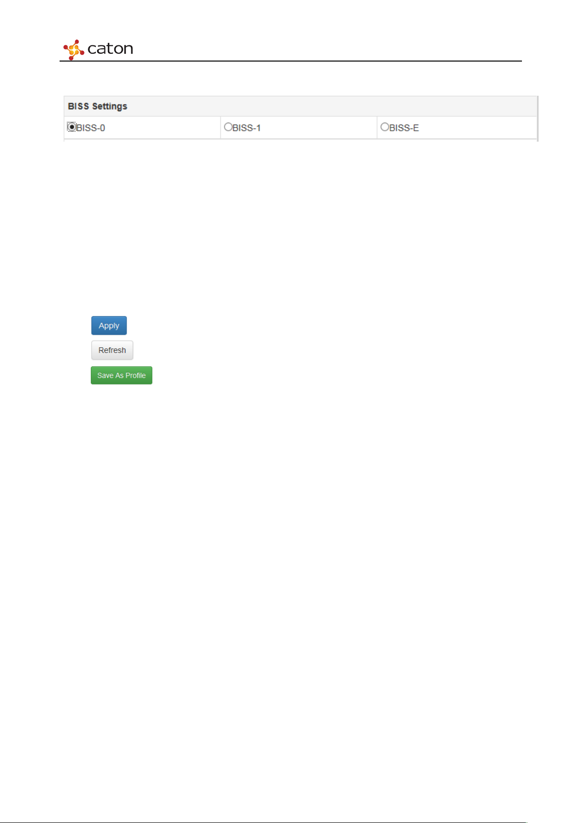
5. BISS Settings
Figure 5.17 BISS Settings
BISS encryption settings for current encoding channel:
BISS-0:None BISS decryption.
BISS-1:BISS-1 decryption. Session Word should be 12 numbers.
BISS-E:BISS-E decryption. Session Word should be 16 numbers. Inject ID should be 14
numbers.
Click to save the configuration.
Click to refresh current page.
Click to save the configuration as a profile. User can apply this configuration to
other HDE-420/422 module by uploading the profile.
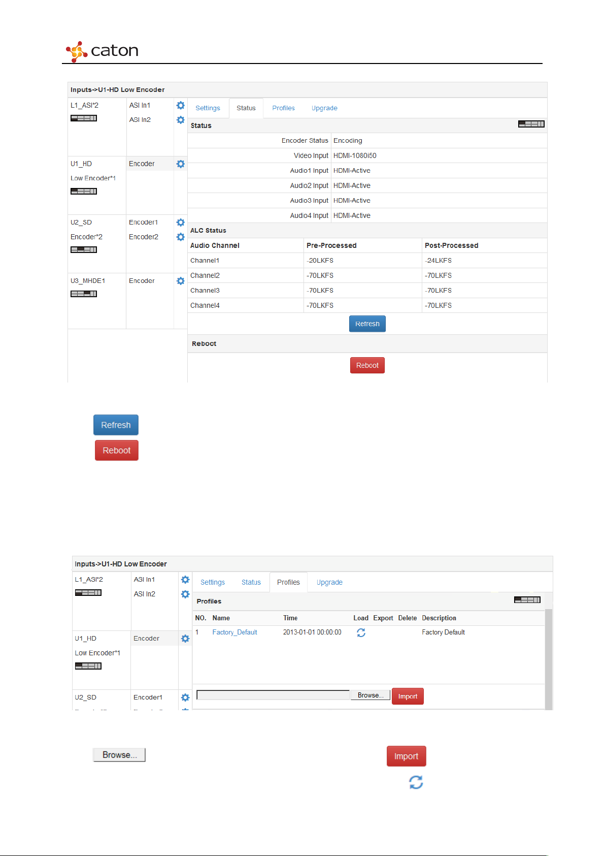
5.4.1.2 Status
Select Status column to view the encoding status and ALC status.
Page 41
Web Control
Figure 5.18 Status
Click to refresh current page.
Click to reboot HDE-420/422 module.
5.4.1.3 Profiles
Select Profiles column to upload the configuration file.
Figure 5.19 Profiles
Click to select the configuration file in PC, click to upload the file to
IVP-3000. Choose the configuration file in Profiles column and click to apply. User can also
Page 42
Web Control
load the Factory Default file to recover to the default settings.
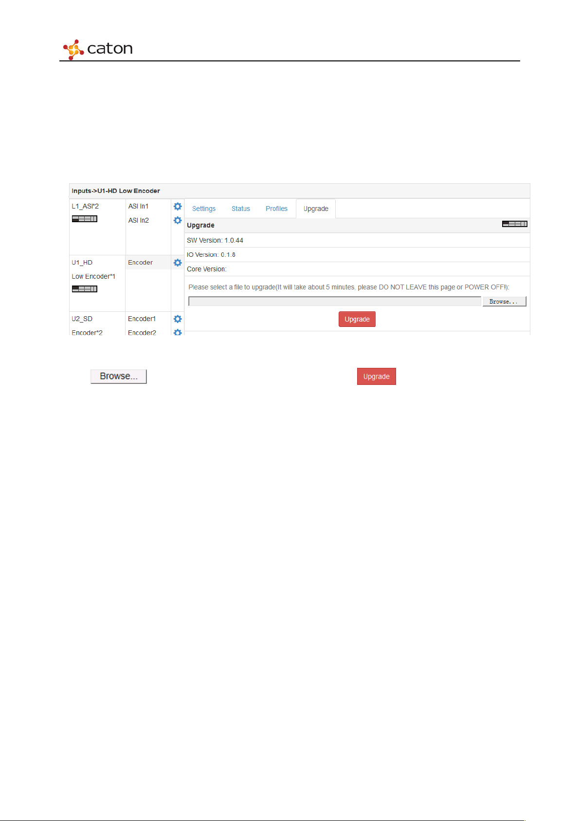
5.4.1.4 Upgrade
Select Upgrade column to upgrade HDE-420/422 software on web UI.
Figure 5.20 Upgrade
Click to select upgrade package in PC and click to upgrade. The upgrade
will take about 5 minutes, please do not leave this page or power off.
Page 43
Web Control
5.4.2 SD Digital/Analog Encoder Module (SDE-420)
Click in Encoder*2 bar to configure SDE-420 module. SDE-420 module support source*2
encoding, user can configure 2 encoders separately. Click Encoder1/Encoder2 bar to configure
each encoder.
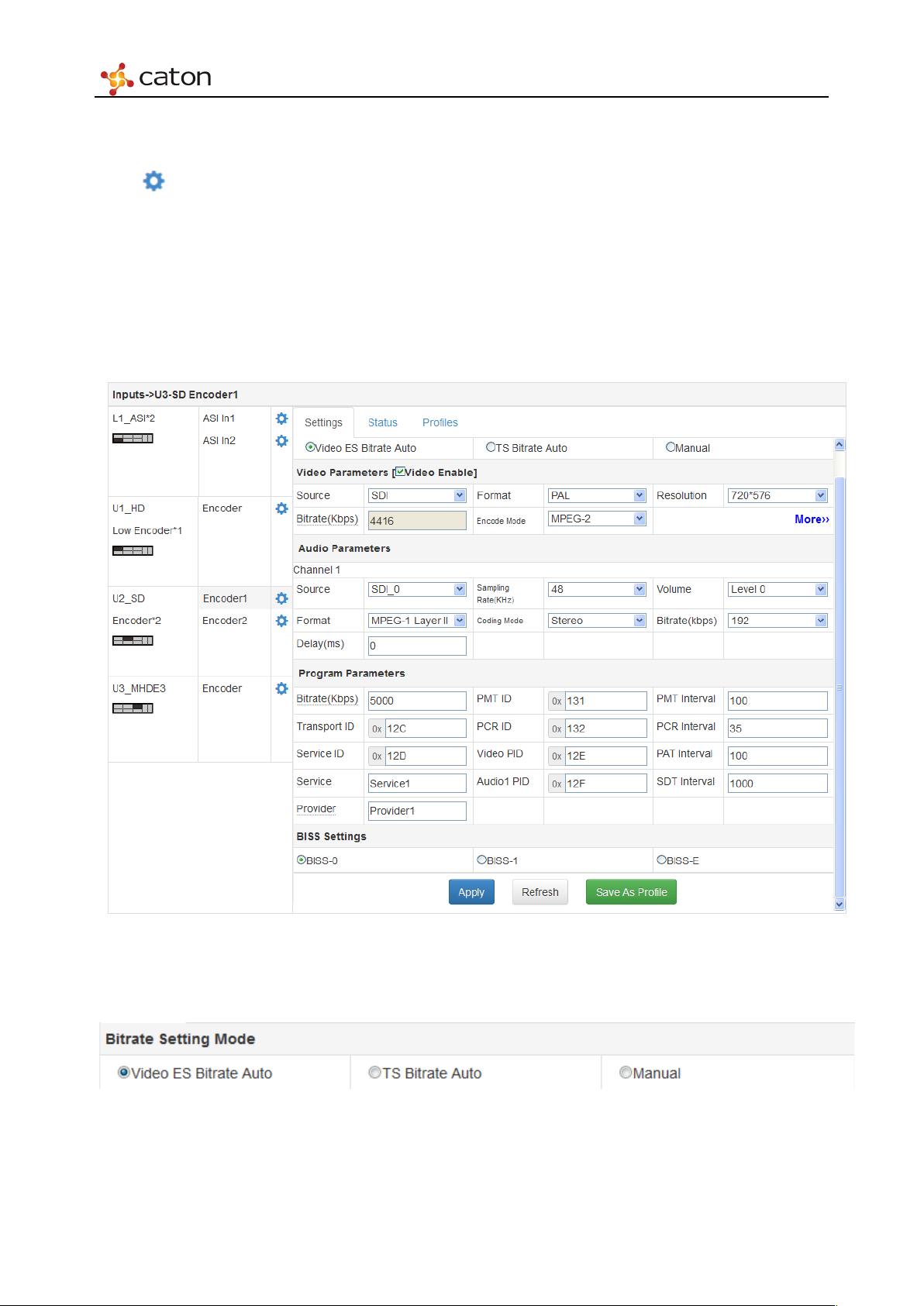
5.4.2.1 Settings
Select Settings column to configure basic encoding settings of SDE-420.
1. Bitrate Setting Mode
Video ES Bitrate Auto:
Figure 5.21 Setting
Figure 5.22 Bitrate Setting Mode
Page 44
Web Control
Video ES Bitrate cannot be editable and will be calculated automatically from TS Bitrate
TS Bitrate Auto:
TS Bitrate cannot be editable and will be calculated automatically from Video ES Bitrate
Manual:
Video ES Bitrate and TS Bitrate will be decided both by user.
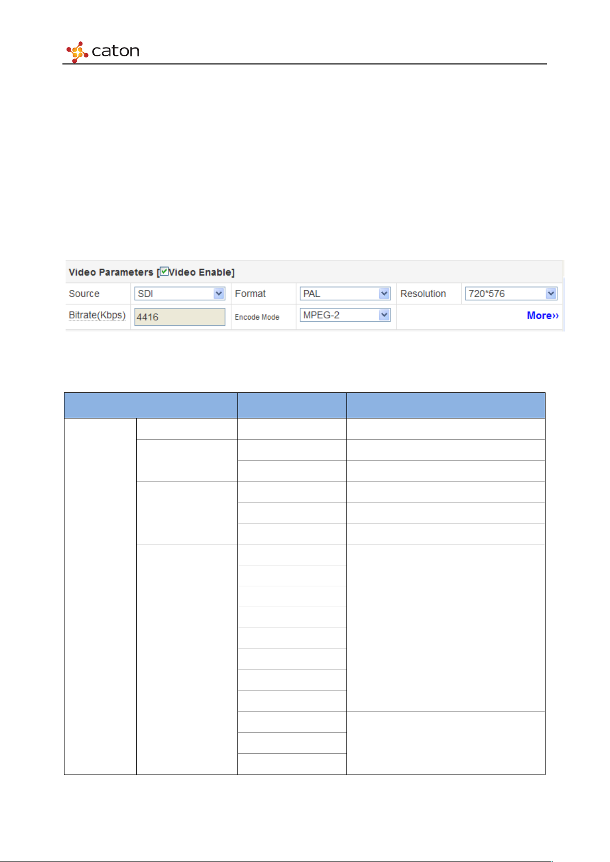
2. Video Parameters
Figure 5.23 Video Parame ters
Vid eo
Parameters
Ta bl e 5.4 Video Parameters
Item Option Comment
Video Enable On/Off Click off to encode audio source only
SDI
Source
CVBS
PAL
Format
Resolution
NTSC/29.97
NTSC/30
720*576
704*576
640*576
544*576
PA L
528*576
352*576
352*288
320*240
720*480
704*480
640*480
NTSC
Page 45
Web Control
528*480
352*288
250~6000
H.264 Single-Channel
500~7000
MPEG-2 Single-Channel
H.264
No IDRs
Every second I Frame
Main
Automatic
H.264/MPEG-2
Level2.0
544*480
352*480
320*240
250~15000 H.264 Twin-Channel
Video Bitrate
500~15000 MPEG-2 Twin-Channel
Encoder Mode
MPEG-2
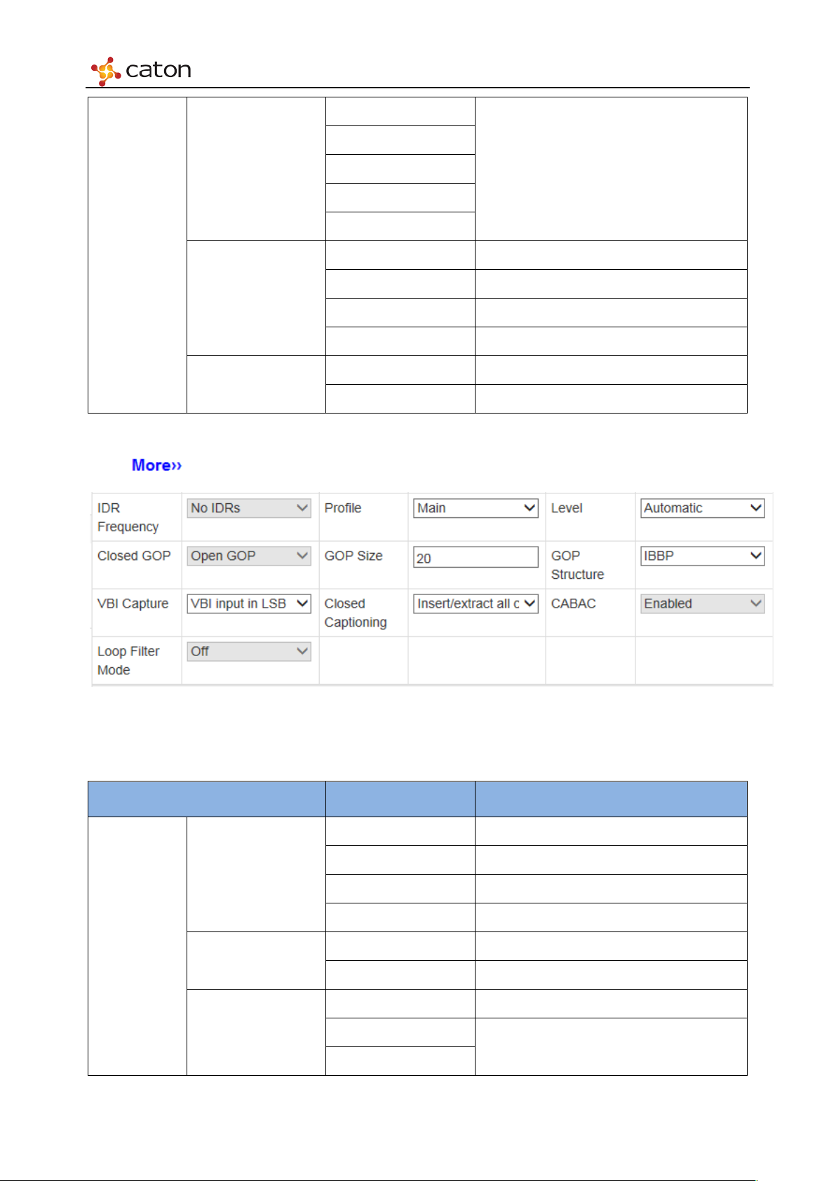
Click to configure advanced video parameters.
More
Parameters
Figure 5.24 More Parameters
Ta bl e 5.5 More Parameters
Item Option Comment
Every I Frame
IDR Frequency
Every third I Frame
Profile
H.264 Baseline
Level
Level1.3
H.264
Page 46

Web Control
Level2.2
Main
MPEG-2
Close GOP
IP
IBBP
VBI input in MSB
EIA608B field 1 and 2
EIA608B field 2
Disable
Off
boundaries
Level2.1
Level3.0
Open GOP
Closed GOP
GOP Size 1 to 255
GOP Structure
VBI Capture
Closed Captioning
IBP
VBI input in LSB
Insert/extract all
captions
Insert/extract
Insert/extract
EIA608B field 1
Insert/extract
Insert/extract
EIA608B
CABAC
Loop Filter Mode
Enable
On
Not across slice
Page 47
Web Control
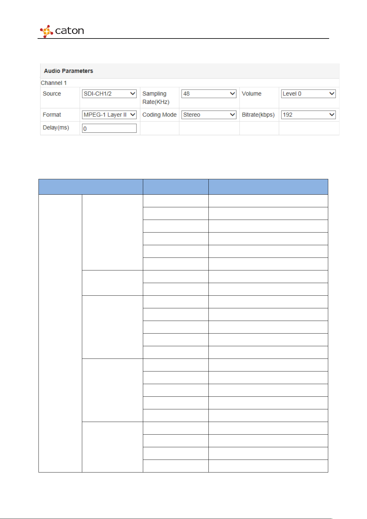
3. Audio Parameters
Figure 5.25 Audio Parameters
Ta bl e5 .6 Audio Parameters
Item Option Comment
SDI-Ch1/2
Audio
Parameters
Source
Sampling
Rate(KHZ)
Volume
Format
SDI-Ch3/4
SDI-Ch5/6
SDI-Ch7/8
Analog
AES/EBU
48 SDI or AES/EBU Source
32/44.1/48 Analog Source
Level 0
Level 1
Level 2
Level 3
Level 4
MPEG-1 Layer II
AAC-LC
HE-AAC V1
Coding Mode
HE-AAC V2
AC3 Bypass
Dual-mono
Stereo
Mono L
Mono R
Page 48
Web Control
32
64
96
128
192
320
448
576
Delay(ms)
0~1000
Transport ID
0x0 to 0xFFFF
Mono L/R
48
80
112
160
Bitrate(kbps)
224
384
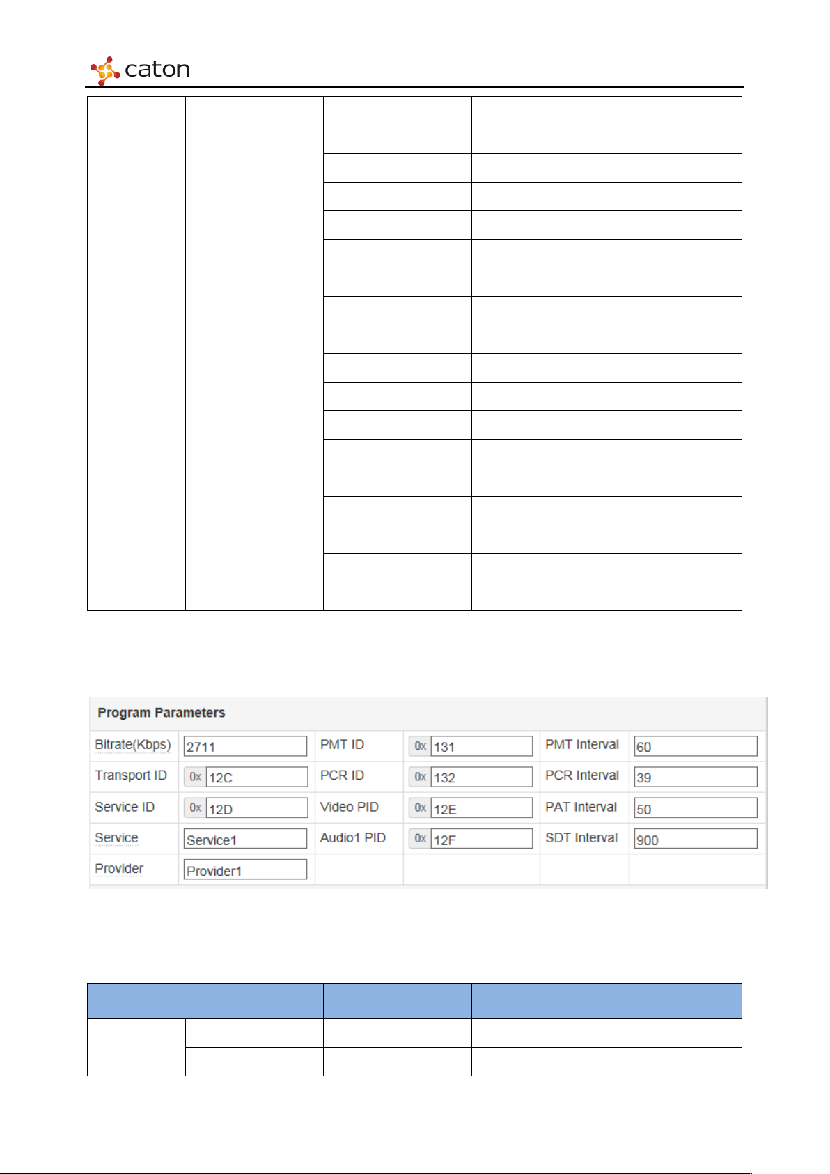
4. Program Parameters
512
640
Figure 5.26 Program Parameters
Parameters
PSI/SI
Ta bl e 5.7 Program Parameters
Item Option Comment
Bitrate(Kbps) 500~20000
Page 49
Web Control
Service
<Custom>
PMT ID
0x20 to 0x1FFE
Video PID
0x20 to 0x1FFE
PMT Interval
1~500ms
PAT Interval
1~500ms
Service ID 0x0 to 0xFFFF
Provider <Custom>
PCR ID 0x20 to 0x1FFE
Audio1 PID 0x20 to 0x1FFE
PCR Interval 1~40ms
SDT Interval 1~10000ms
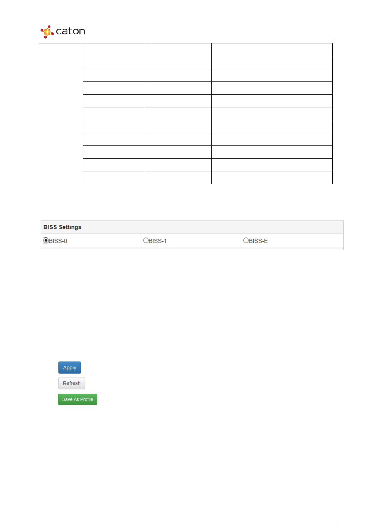
5. BISS Settings
Figure 5.27 BISS Settings
BISS encryption settings for current encoding channel:
BISS-0:None BISS decryption.
BISS-1:BISS-1 decryption. Session Word should be 12 numbers.
BISS-E:BISS-E decryption. Session Word should be 16 numbers. Inject ID should be 14
numbers.
Click to save the configuration.
Click to refresh current page.
Click to save the configuration as a profile. User can apply this configuration to
other SDE-420 module by uploading the profile.
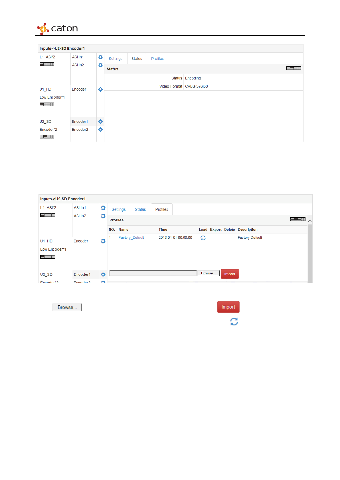
5.4.2.2 Status
Select Status column to view the encoding status and input format.
Page 50
Web Control
Figure 5.28 Status
5.4.2.3 Profiles
Select Profiles column to upload the configuration file.
Figure 5.29 Profiles
Click to select the configuration file in PC, click to upload the file to
IVP-3000. Choose the configuration file in Profiles column and click to apply. User can also
load the Factory Default file to recover to the default settings.
Page 51
Web Control
5.4.3 Multi-stream HD Digital Encoder Module (MHDE-420)
Click in MHDE3 bar to configure MHDE-420 module.
5.4.3.1 Settings
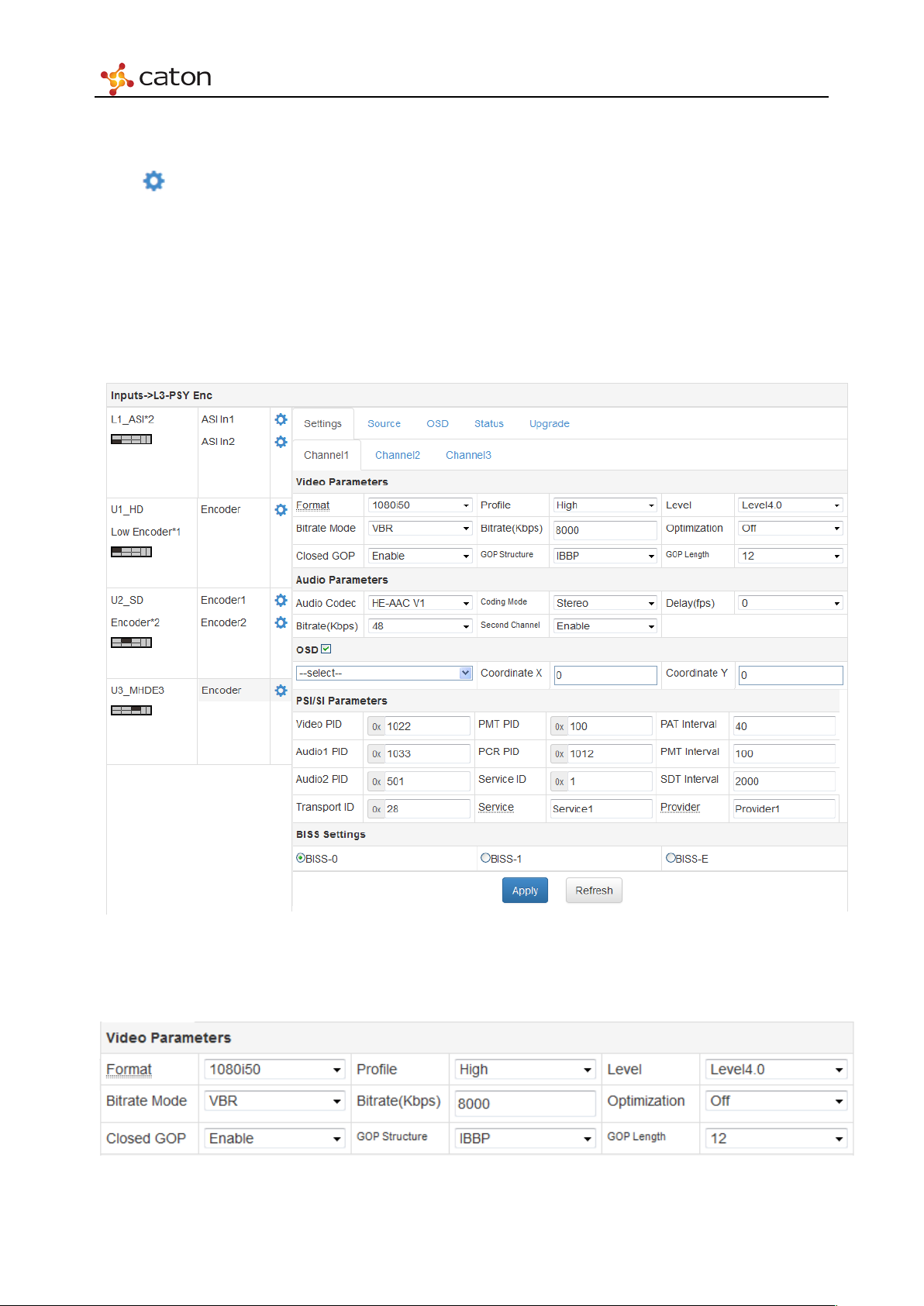
Select Settings column to configure basic encoding settings of MHDE-420. MHDE-420 module
support 3 encoding streams output, user can configure 3 encoding channels separately. Click
Channel1/Channel2/Channel3 column to configure each encoding channel.
1. Video Parameters
Figure 5.30 Settings
Figure 5.31 Video Para meters
Page 52
Web Control
1080p59.94/50
1920x1080p59.94/50
1080i59.94/50
1920x1080i59.94/50
720p25
1280x720p25
576p25
720x576p25
480p29.97
720x480p29.97
360p29.97
640x360p29.97
240p29.97
352x240p29.97
Main
Level2.0
Level2.2
Level3.1
Level4.0
Level4.2
VBR
Off
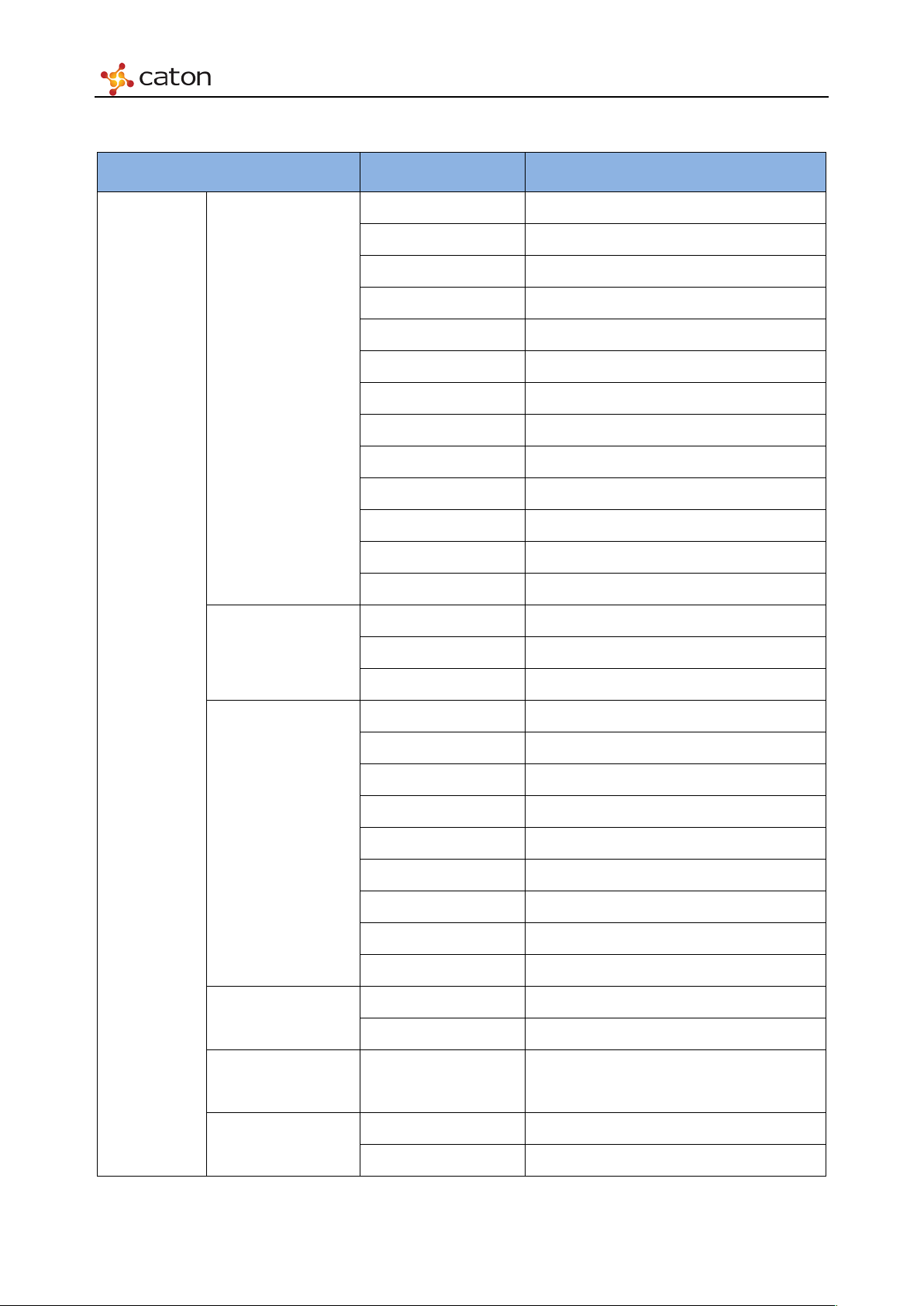
Ta bl e 5.8 Vid eo P arameters
Item Option Comment
1080p29.97/25 1920x1080p29.97/25
720p59.94/50 1280x720p59.94/50
576i50 720x576i50
Format
480i59.94 720x480i59.94
360p25 640x360p25
Vid eo
Parameters
Profile
Level
Bitrate Mode
288p25 352x288p25
Baseline
High
Level2.1
Level3.0
Level3.2
Level4.1
CBR
Bitrate(Kbps)
0.5~20Mbps
HD:1~20Mbps
SD:0.5~20Mbps
Optimization
Medium Horizontal 3/4 sampling
Page 53
Web Control
(1920x1080i59.94, 1920x1080i50)
Disable
IBBP
24
Almost frames in 1000ms
(1920x1080P59.94, 1920x1080P50,
1920x1080i59.94, 1920x1080i50)
Closed GOP
GOP Structure
GOP Length
2. Audio Parameters
High
Horizontal 1/2 sampling
Enable
IP
12 Almost frames in 500ms
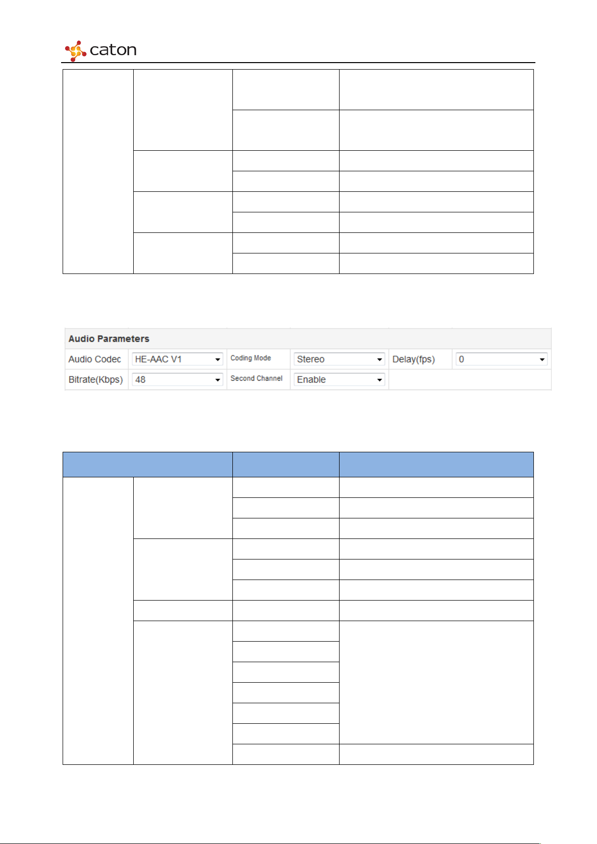
Figure 5.32 Audio Parameters
Audio
Parameters
Ta bl e5 .9 Audio Parameters
Item Option Comment
AAC-LC
Audio Codec
Coding Mode
Delay(fps) -15.5~15.5 Relative to video
Bitrate(kbps)
MPEG1 Layer-2
HE-AAC V1
Dual Mono
Stereo
Mono L/R
96
128
192
256
384
AAC-LC
512
128
MPEG1 Layer-2
Page 54
Web Control
256
64
192
48
HE-AAC V1
audio encoding parameters need to be the same, but with different audio PID to identify them.
3. OSD
Click on OSD to enable OSD function. After the pictures are uploaded to IVP-3000 in OSD
column, select the picture in IVP-3000 as OSD and set Coordinate X and Coordinate Y to
Tips:
MHDE-420 support 2 channel audio encoding with different audio source. In that case, the
Figure 5.33 OSD
configure the position of OSD. ( Left front corner is <0, 0>, OSD move to the right for 1 pixel as
Coordinate X add 1, and move to the bottom for 1 pixel as Coordinate Y add 1)
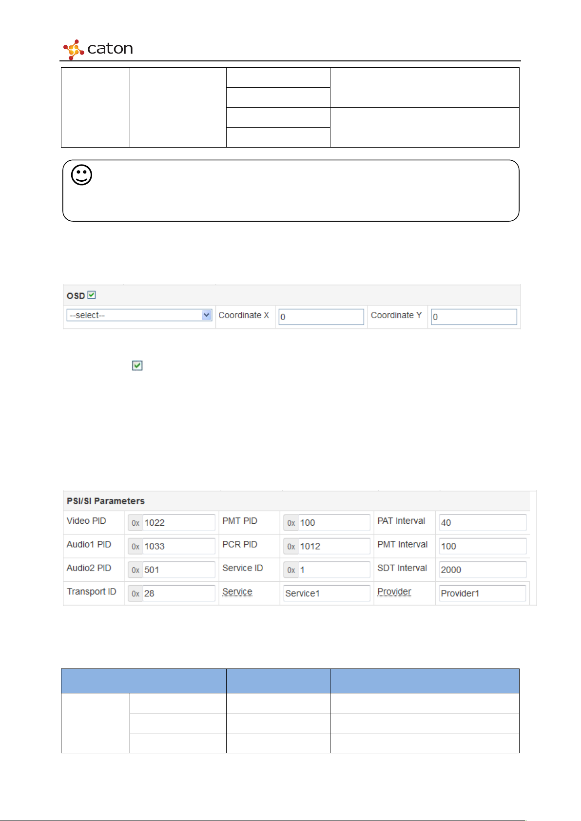
4. PSI/SI Parameters
Figure 5.34 PSI/SI Parameters
Ta bl e5.10 PSI/SI Parameters
Item Option Comment
Video PID 0x20 to 0x1FFE
PSI/SI
Audio1 PID 0x20 to 0x1FFE
Parameters
Audio2 PID 0x20 to 0x1FFE
Page 55
Web Control
0x20 to 0x1FFE
Service ID
0x1 to 0xFFFF
PAT Interval
1~100ms
SDT Interval
1~10000ms
Transport ID 0x1 to 0xFFFF
PMT PID
PCR PID
Service <Custom>
PMT Interval 1~100ms
Provider <Custom>
0x20 to 0x1FFE
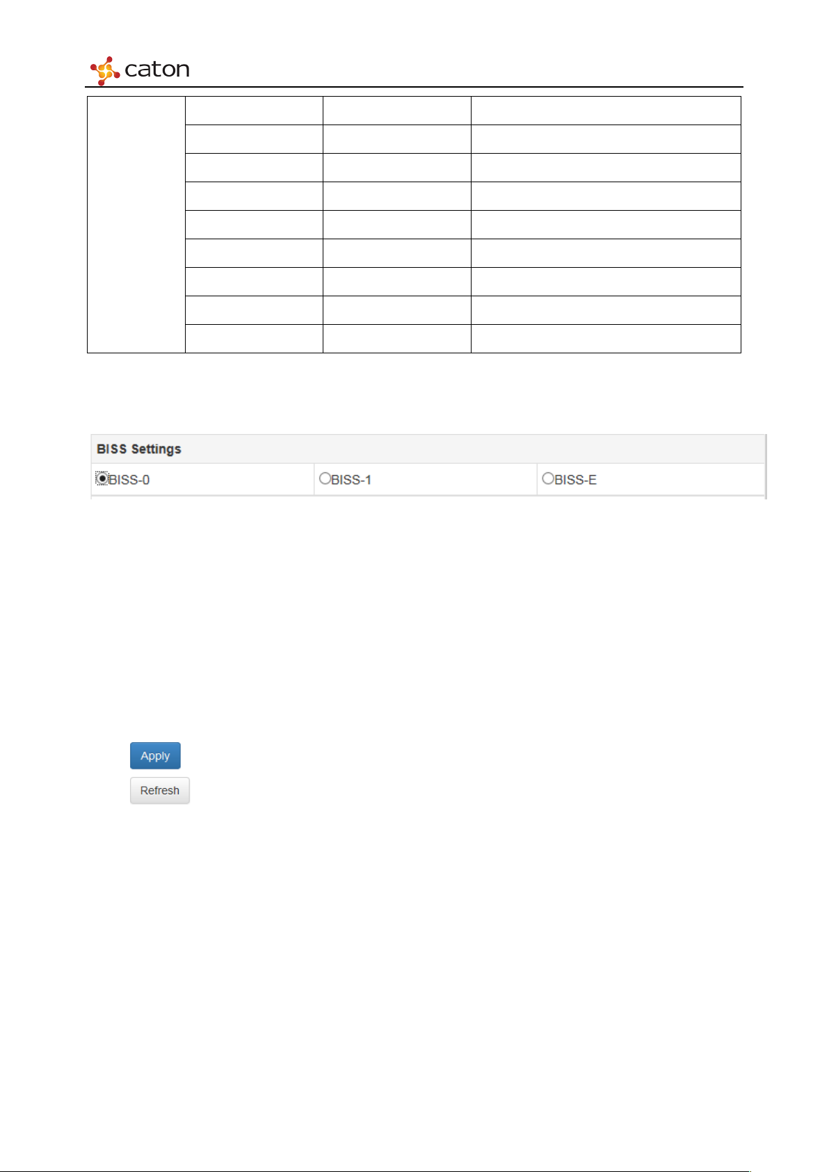
5. BISS Settings
Figure 5.35 BISS Settings
BISS encryption settings for current encoding channel:
BISS-0:None BISS decryption.
BISS-1:BISS-1 decryption. Session Word should be 12 numbers.
BISS-E:BISS-E decryption. Session Word should be 16 numbers. Inject ID should be 14
numbers.
Click to save the configuration.
Click to refresh current page.
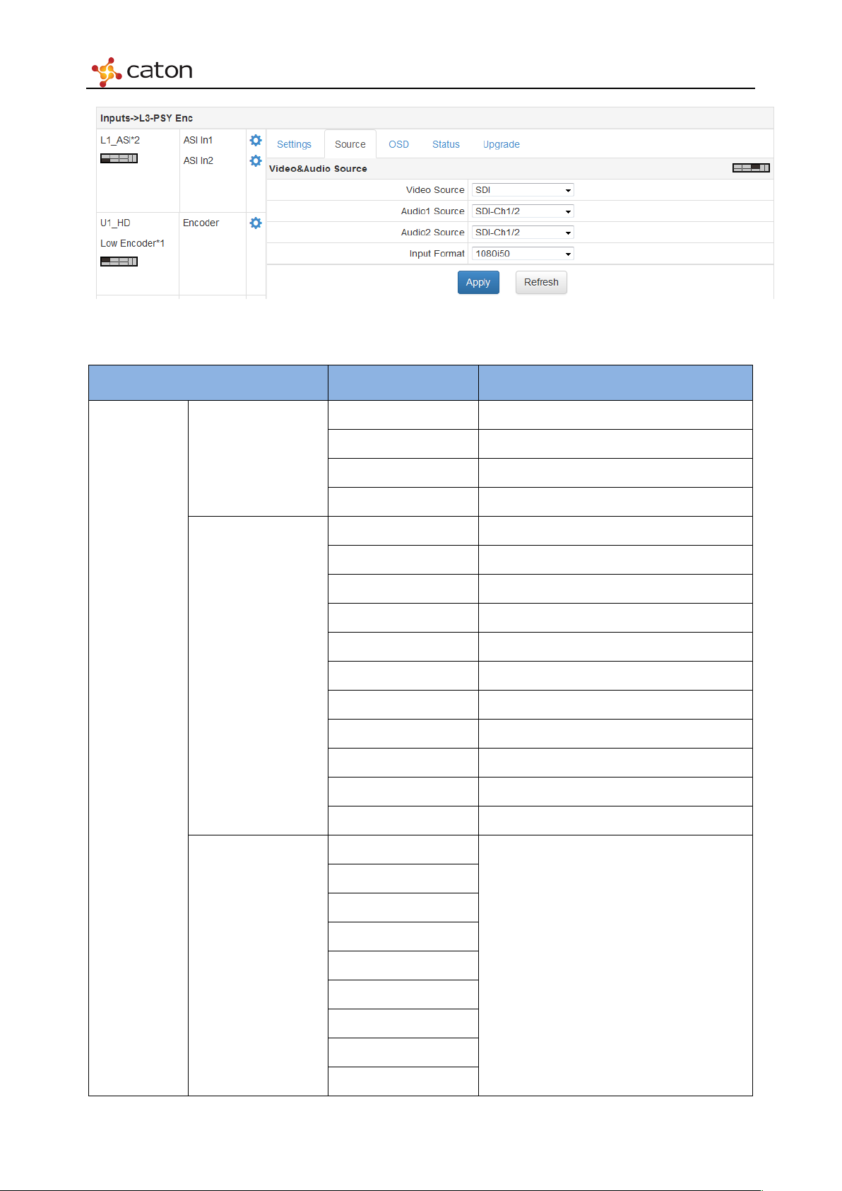
5.4.3.2 Source
Select Source column to choose video & audio source to encode.
Page 56
Web Control
Figure 5.36 Source
Ta bl e 5.11 Source Parameters
Item Option Comment
SDI
HDMI
Video Source
ColorBar
Vid eo&Audio
Source
BlackField
Analog1
Analog2
SDI-Ch1/2
SDI-Ch3/4
SDI-Ch5/6
Audio1 Source/
SDI-Ch7/8
Audio2 Source
HDMI-Ch1/2
HDMI-Ch3/4
HDMI-Ch5/6
HDMI-Ch7/8
1KHz
1080p59.94
1080p50
1080p29.97
Input Format
1080p25
1080i59.94
1080i50
720p59.94
720p50
480i59.94
Make sure to be the same with actual input
source format (format in status column),
otherwise input source will be colorbar
Page 57
Web Control
576i50
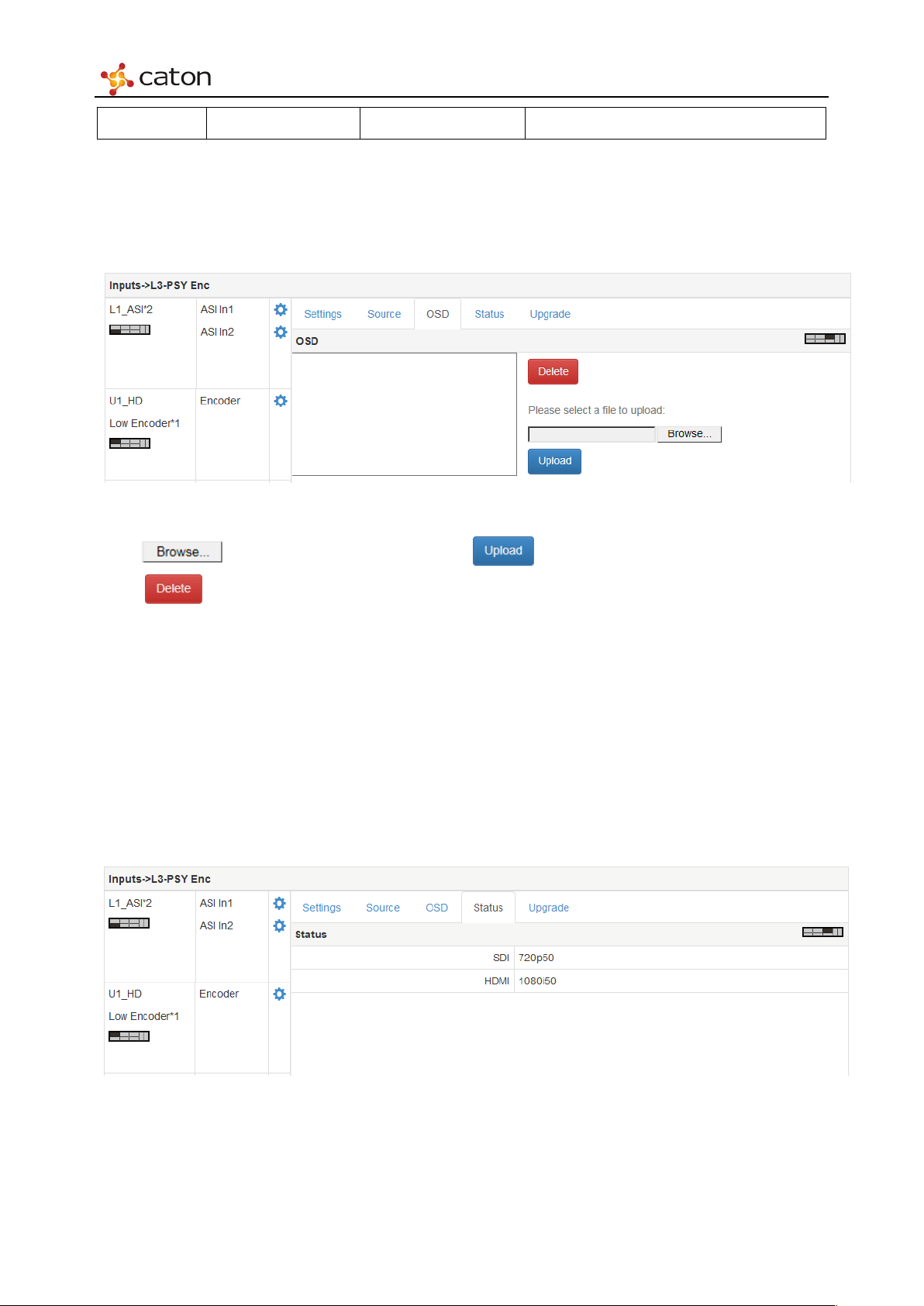
5.4.3.3 OSD
Select OSD column to upload picture files to IVP-3000 as OSD options.
Figure 5.37 OSD
Click to select picture file in PC, click to upload it to IVP-3000.
Click to remove the file from IVP-3000.
Picture Format: PNG. file
Quantity: Up to 3 pictures
Size: Width pixel should be multiple to 128\
5.4.3.4 Status
Select Status column to view the format of SDI/HDMI source.
Figure 5.38 Status
Page 58
Web Control
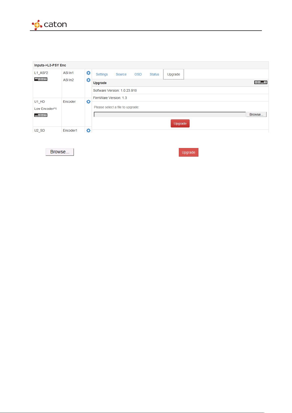
5.4.3.5 Upgrade
Select Upgrade column to upgrade MHDE-420 software on web UI.
Figure 5.39 Upgrade
Click to select upgrade package in PC and click to upgrade. The upgrade
will take about 5 minutes, please do not leave this page or power off.
Page 59
Web Control
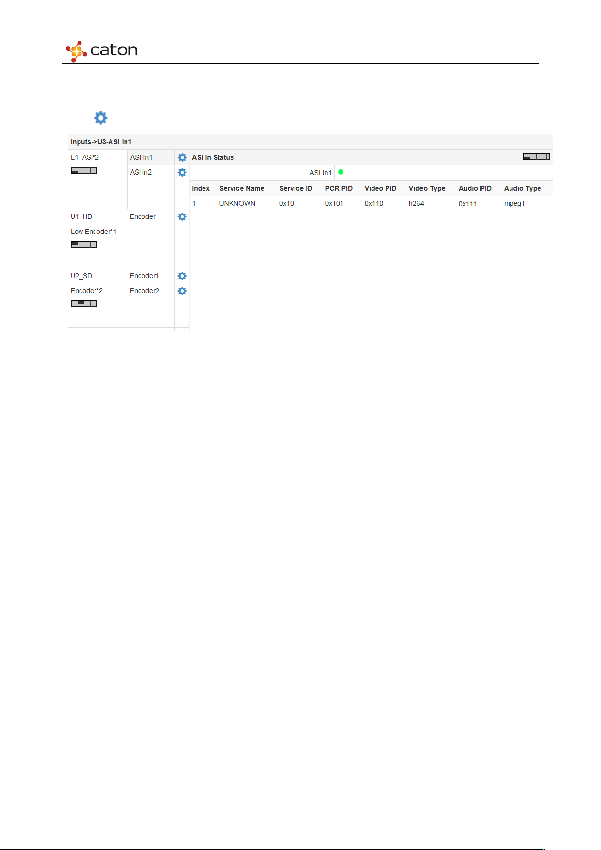
5.4.4 ASI I/O Module (IO-ASI)
Click in ASI In1/2/3/4 bar to view ASI input info.
Figure 5.40 ASI Input
ASI In Status Column will display the input status and source info of current ASI channel. If the
indicator shows red, it means there is no input in current ASI channel.
Page 60
Web Control
5.5 TS Processor Setting
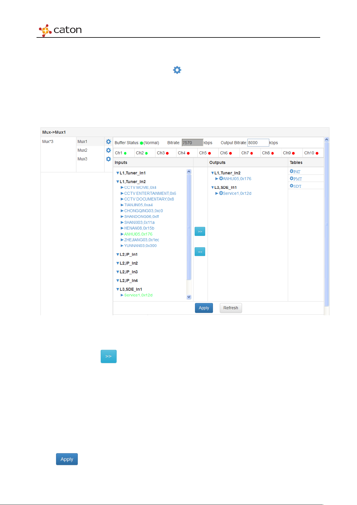
Click TS Processor in main menu, and click in Mux*3 bar to configure the Mux module.
Mux module consists of 3 multiplexer. Each multiplexer support 10 input port, and maximum10
input source can be selected. Each multiplexer support 256 PID filter and remap, and support 41
table insert.
Figure 5.41 TS Processor Settings
The service ID of all TS in IVP-3000 will displays in Inputs column. Select the service that need
to mux/de-mux, click to move the service to Outputs column.
Buffer Status: Each multiplexer support 10 input port. Each input port with a input buffer. If
the buffer overflow the indicator will turn red otherwise it is green.
Bitrate: Total calculatedbitrate input to the multiplexer.
Output Bitrate: The actual output bitrate that set by users. To avoid the suffer overflow,
Output Bitrate must be greater than Bitrate. More than 10% of the margin is the best.
Click to save the configuration.
Page 61
Web Control
0
EIT Present Flag 0
Click to refresh current page.
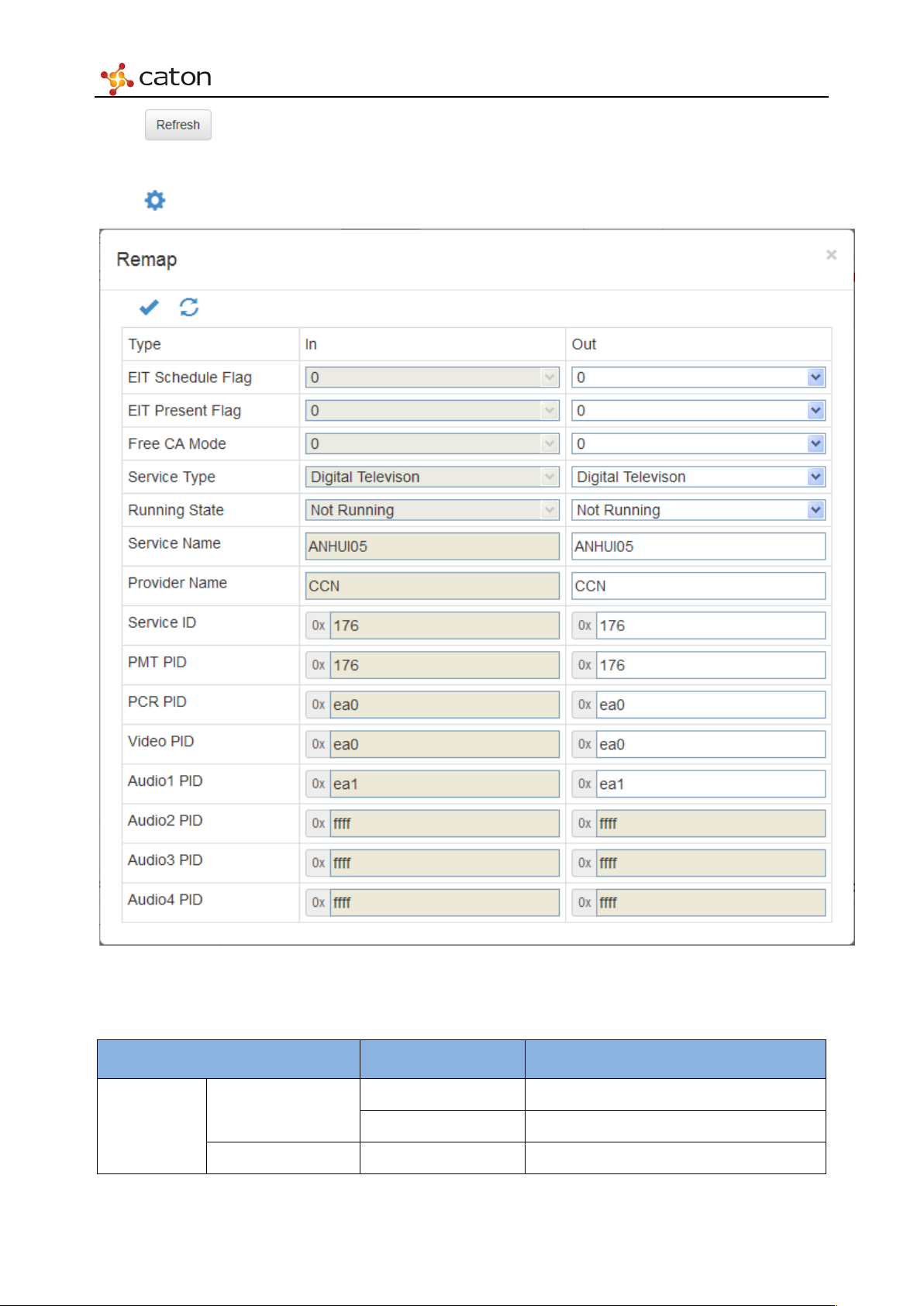
Click beside of service ID in Outputs column to configure the remap setting of mux/de-mux.
Remap
Figure 5.42 Remap
Ta bl e 5.12 Remap parameters
Item Option Comment
EIT Schedule Flag
1
Page 62
Web Control
0
Service Type
Digital Television etc.
Start in a few seconds
Running
Service Name
<Custom>
Service ID
0x1~0xFFFE
PCR PID
0x20~0xFFFE
Audio1~4 PID
0x20~0xFFFE
If you want to remove it, set it to 0xFFFF
1
Free CA Mode
1
Not Running
Running State
Provider Name <Custom>
PMT PID 0x20~0xFFFE
Video PID 0x20~0xFFFE If you want to remove it, set it to 0xFFFF
Click to save the configuration.
Click to reset the settings.
Pausing
Service off-air
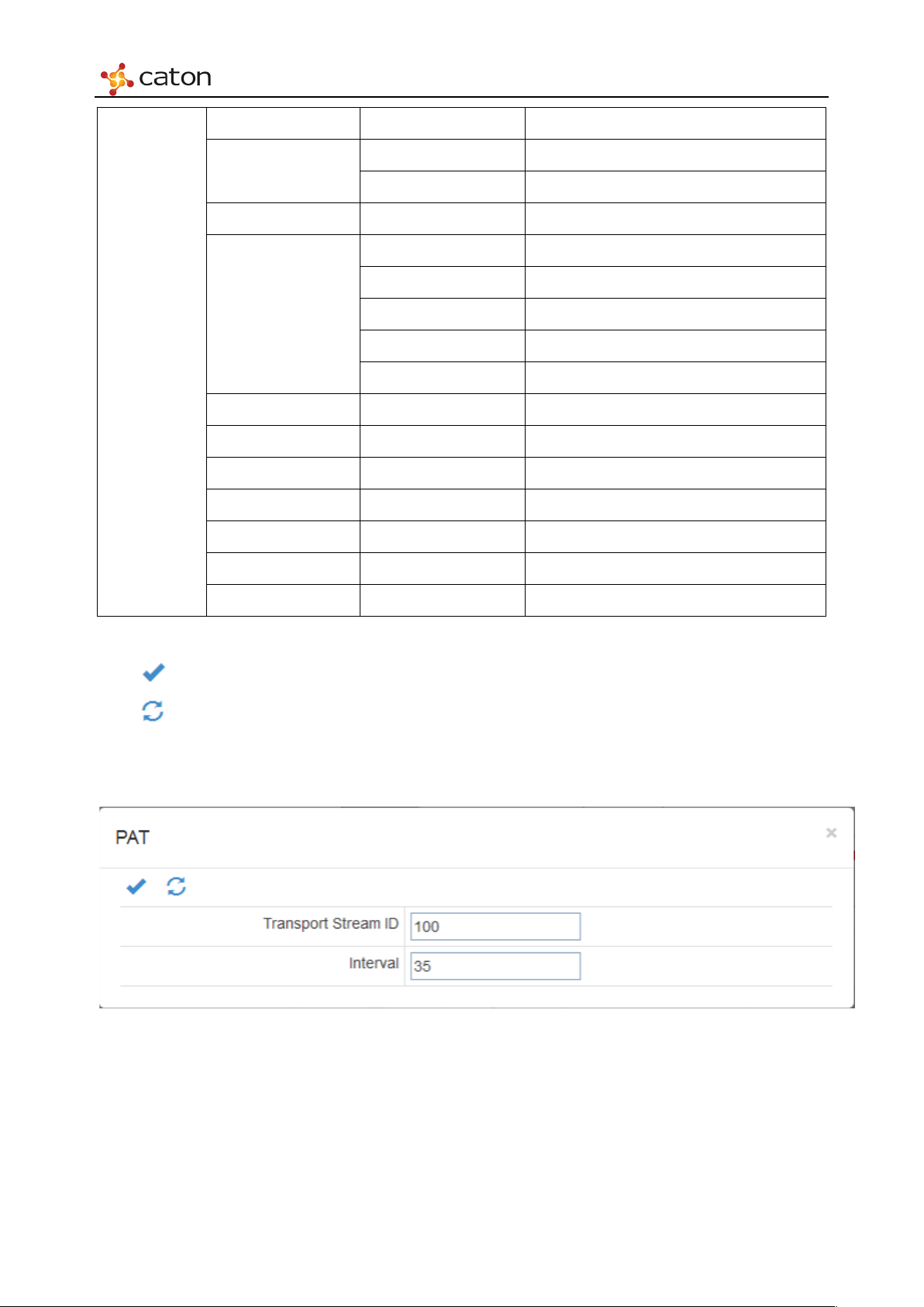
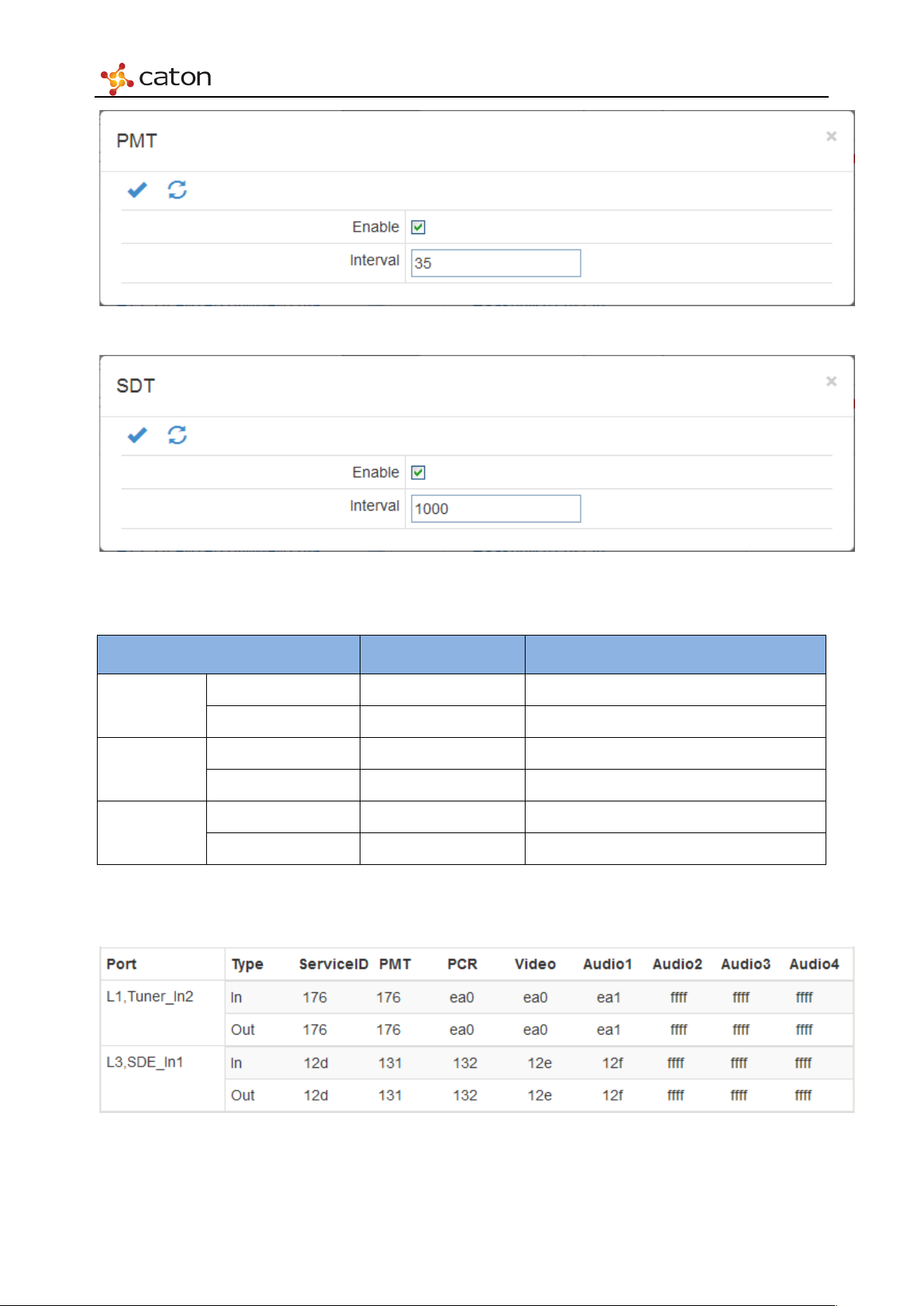
In Tables column, user can configure PAT, PAT and SDT tables.
Figure 5.43 PA T
Page 63
Web Control
Figure 5.44 PMT
Figure 5.45 SDT
Ta bl e 5.13 Tabl es
Item Option Comment
Transport ID <Custom>
PAT
Interval <Custom>
Enable On/Off
PMT
Interval <Custom>
Enable On/Off
SDT
Interval <Custom>
At the bottom of Mux setting page, user can view program parameter of programs in
mux/de-mux.
Figure 5.46 Program
Page 64
Web Control
5.6 R2TP Processor Setting
Click R2TP Processor in main menu to open the SMIP IO page.
5.6.1 Stream Port Setting
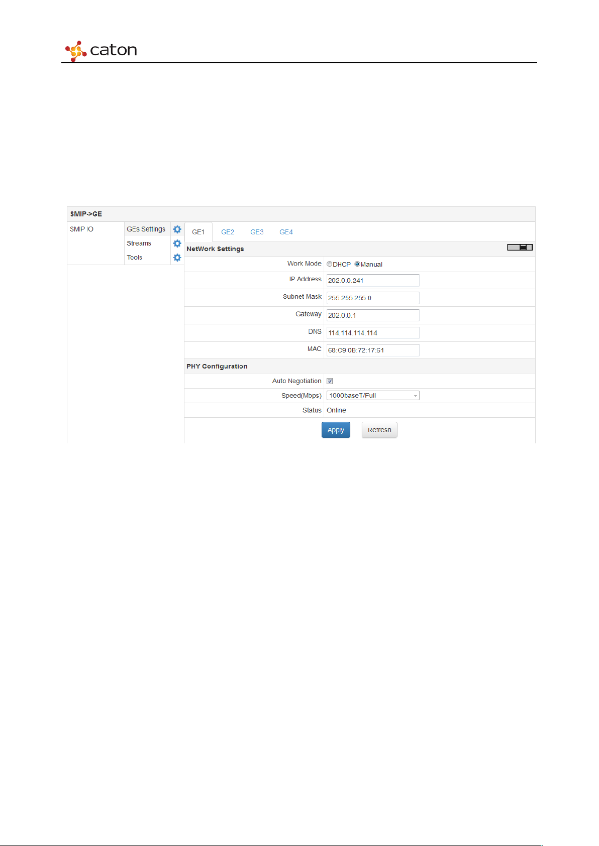
Click GEs Settings to open the stream port setting page, as follows:
Figure 5.47 Stream Port Setting
Network settings and PHY configuration of each stream port (GE1/GE2/GE3/GE4) can be
configured in this page.
5.6.1.1 Network Settings
Work Mode: Stream port IP address mode setting: DHCP or Manual.
In DHCP mode, IP address and other network settings will be configured automatically.
In Manual mode, IP address and other network settings will be configured by user.
IP Address: Stream port IP address setting.
Subnet Mask: Stream port netmask setting.
Gateway: Stream port gateway setting.
DNS: DNS server setting.
MAC: Stream Port MAC address setting. MAC address can only be modified on specific
condition.
Page 65
Web Control
Notice: GE1 and GE2 can’t work in the same network segment. The GE3 & GE4 can’t work on
the same network segment.
5.6.1.2 PHY Configuration
Auto Negotiation: Click to enable the Auto Negotiation function of the interface.
Speed: Select the type of physical layer protocol
Status: Display the status of stream port: Online or Offline.
5.6.2 Transport Streams Setting
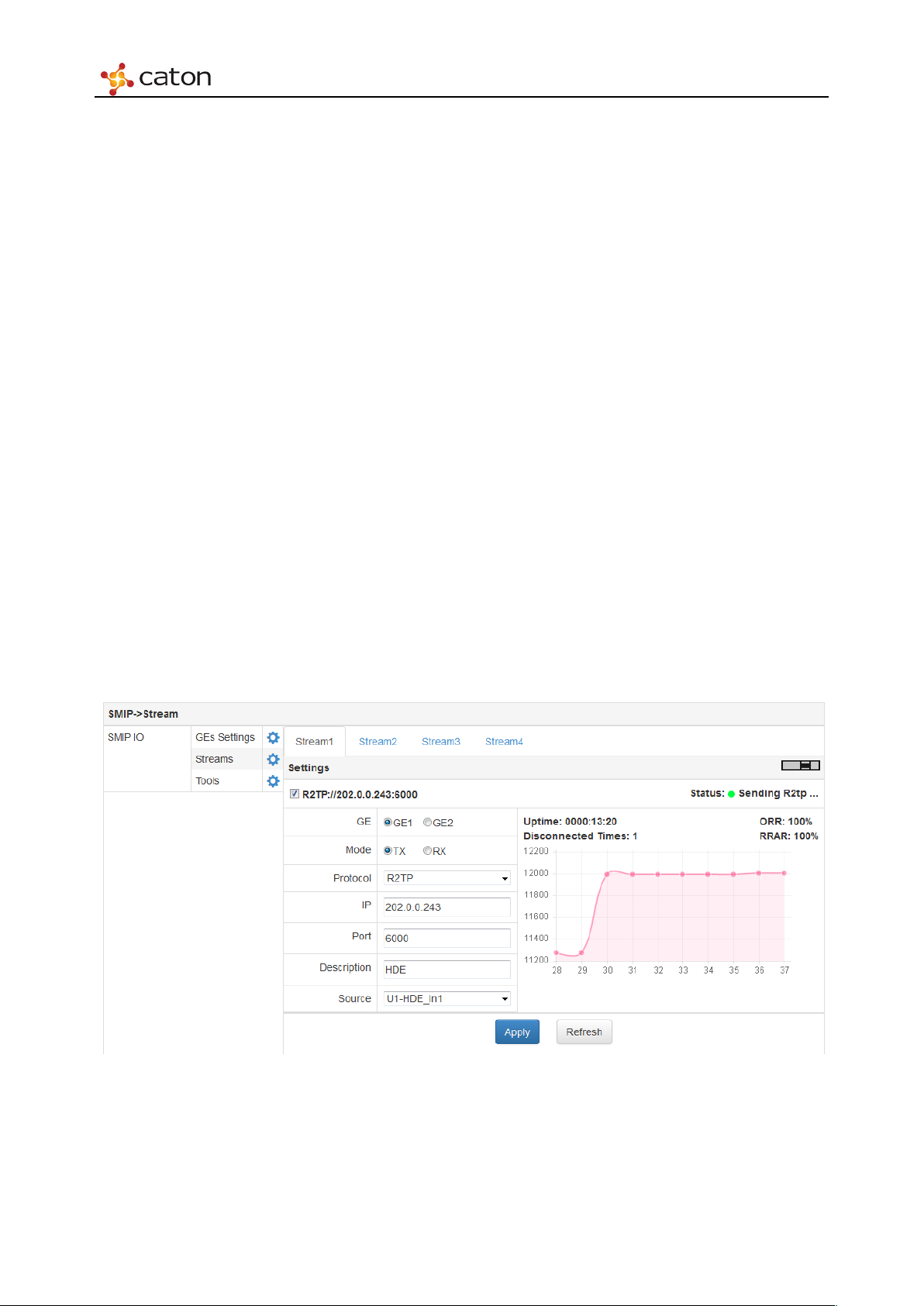
Click Streams to open the transport streams setting page. SMIP module support transferring 4
streams, each stream can be configured independently to select the stream port and work mode.
Stream 1 & Stream 2 can be transmitted/received from GE1/GE2, and Stream 3 & Stream 4 can
be transmitted/received from GE3/GE4.
5.6.2.1 Transmit R2TP/R2TP-S
Figure 5.48 Transmit R2TP/R2TP-S
Page 66
Web Control
Set the R2TP port of TX. Make sure the R2TP port of TX and target RX to be
S port of TX, RRS, and
Transmit R2TP
GE
Mode
Protocol
IP
Port
Description
Source
Transmit R2TP-S
GE
Mode
Select stream port for transmitting: GE1/GE2 or GE3/GE4
Set the work mode: TX (Transmitter)
Select transport protocol: R2TP
Input the IP address of RX of target IVP-3000 device
the same
Describe the stream by custom to identify it
Select the source of the stream to transmit
Select stream port for transmitting: GE1/GE2 or GE3/GE4
Set the work mode: TX (Transmitter)
Protocol
IP
Port
Select transport protocol: R2TP-S
Input the IP address of target R2TP Relay Server(RRS)
Set the R2TP-S port of TX. Make sure the R2TP-
target RX to be the same
Description
Source
Describe the stream by custom to identify it
Select the source of the stream to transmit
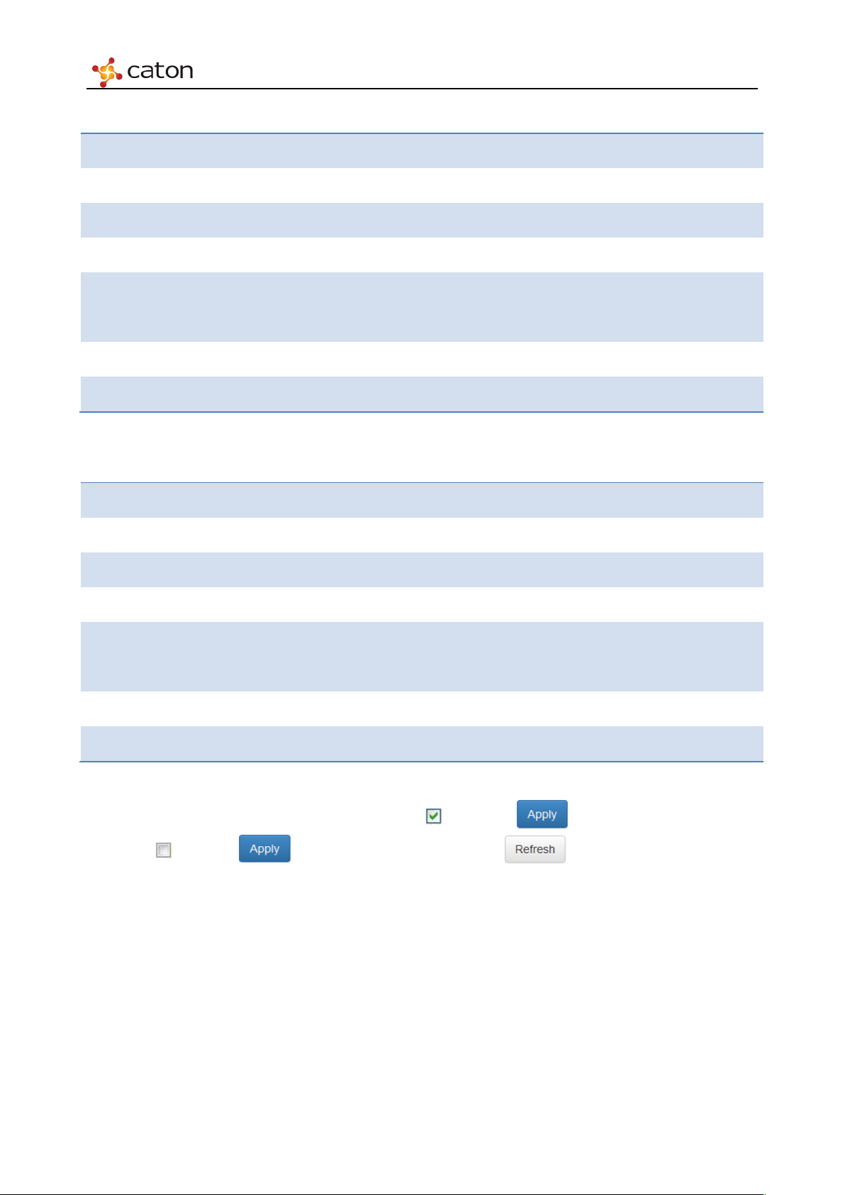
After the transport stream is configured, click on and click to enable the transmitting.
Click off and click to stop the transmitting. Click to refresh current page.
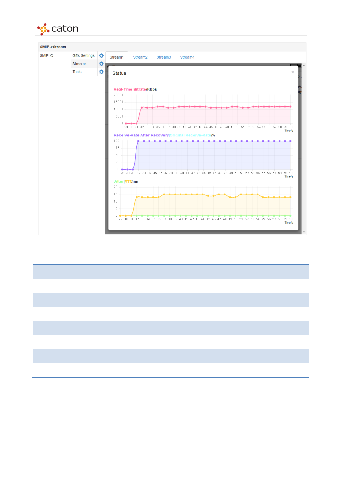
Diagram on the right displays the real-time transmitting bit rate of TX, click the diagram to view
the detailed status statistics, as follows:
Page 67
Web Control
Transmitting Status
Status
Uptime
Disconnected
Bitrate (Kbps)
ORR (%)
RRAR (%)
Jitter (ms)
RTT (ms)
Green icon: the link is connected; Red icon: the link is disconnected
The duration time of current connection
The disconnected time of current connection
Real-time transmitting bit rate of TX
Original receiving ratio of current connection
Receiving ratio after recovery of current connection
The difference value of transmission delay between adjacent packets
Round trip time between TX and target RX
Figure 5.49 Transmitting Status
Page 68
Web Control
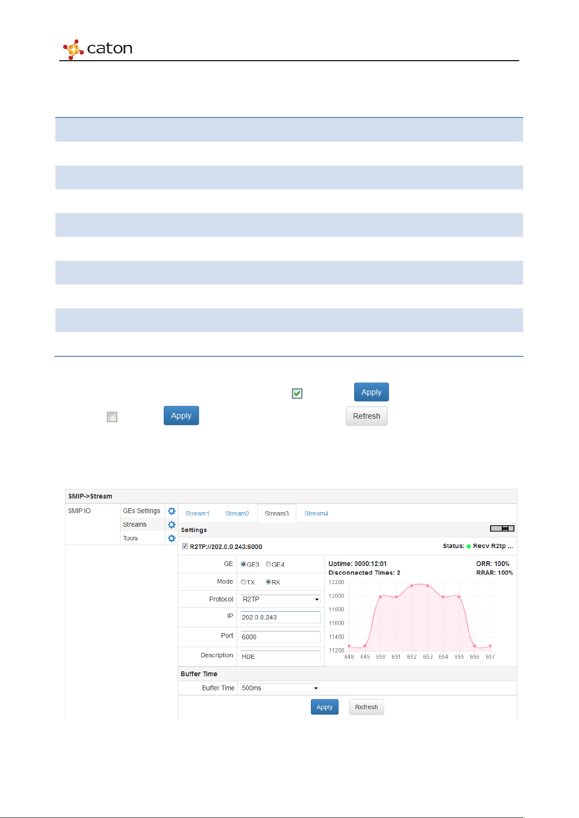
5.6.2.2 Transmit RTMP
Transmit RTMP
GE
Mode
Protocol
IP
Port
Application
Stream
Description
Source
Service List
Select stream port for transmitting: GE1/GE2 or GE3/GE4
Set the work mode: TX (Transmitter)
Select transport protocol: RTMP
Input the IP address of target RTMP server
Input RTMP port of target RTMP server. The default RTMP port is 1935
Input the application info of RTMP stream URL
Input the stream ID of RTMP stream URL
Describe the stream by custom to identify it
Select the source of the stream to transmit
Select the service ID of the stream to transmit
After the transport stream is configured, click on and click to enable the transmitting.
Click off and click to stop the transmitting. Click to refresh current page.
5.6.2.3 Receive R2TP/R2TP-S
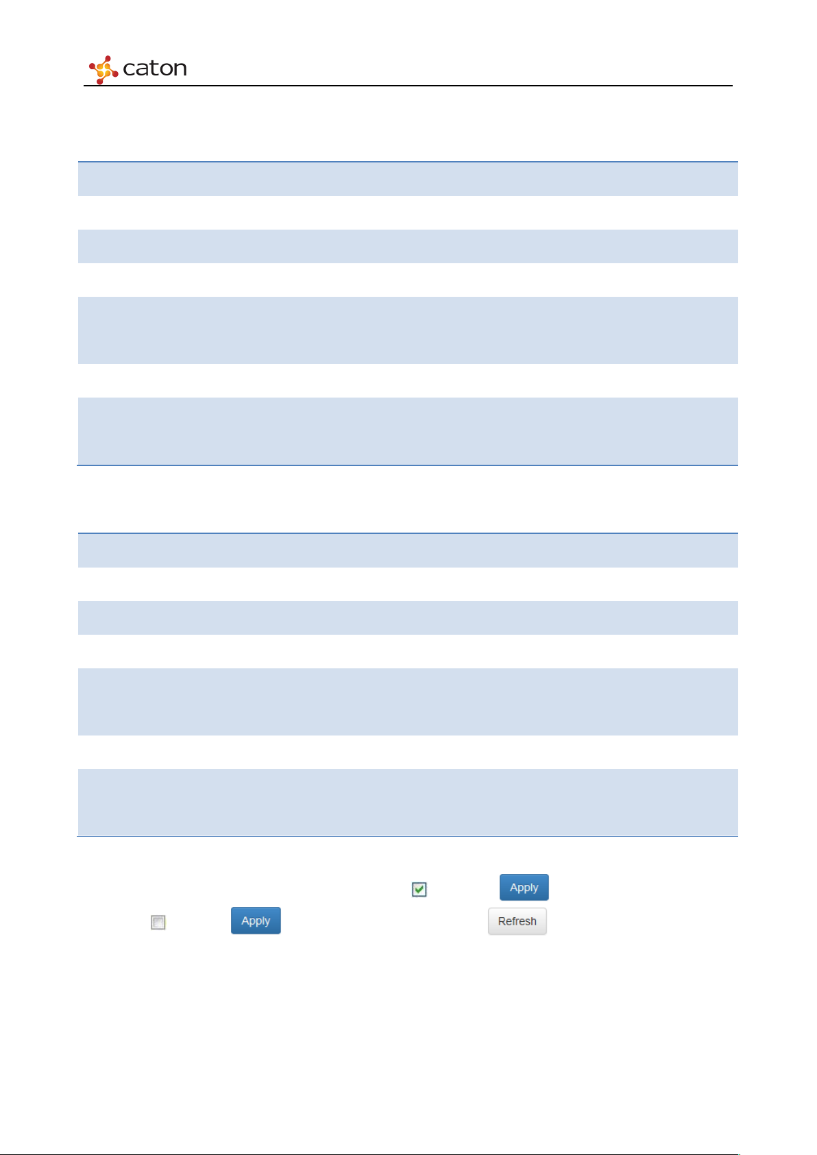
Figure 5.50 Receive R2TP/R2TP-S
Page 69
Web Control
Receive R2TP
GE
Mode
Protocol
IP
Port
Description
Buffer Time
Receive R2TP-S
GE
Select stream port for receiving: GE1/GE2 or GE3/GE4
Set the work mode: RX (Receiver)
Select transport protocol: R2TP
Input the IP address of Local RX
Input the R2TP port of RX. Make sure the R2TP port of TX and RX to be the
same
Describe the stream by custom to identify it
Set buffer time of RX, which refer to network health and user’s need.
Value range: 125ms, 250ms, 500ms, 750ms, 1000ms, 2000ms, 4000ms.
Select stream port for receiving: GE1/GE2/GE3/GE4
Mode
Protocol
IP
Port
Set the work mode: RX (Receiver)
Select transport protocol: R2TP-S
Input the IP address of target R2TP Relay Server(RRS)
Input the R2TP-S port of RX. Make sure the R2TP-S port of TX, RX, and
RRS to be the same
Description
Buffer Time
Describe the stream by custom to identify it
Set buffer time of RX, which refer to network health and user’s need.
Value range: 125ms, 250ms, 500ms, 750ms, 1000ms, 2000ms, 4000ms.
After the transport stream is configured, click on and click to enable the transmitting.
Click off and click to stop the transmitting. Click to refresh current page.
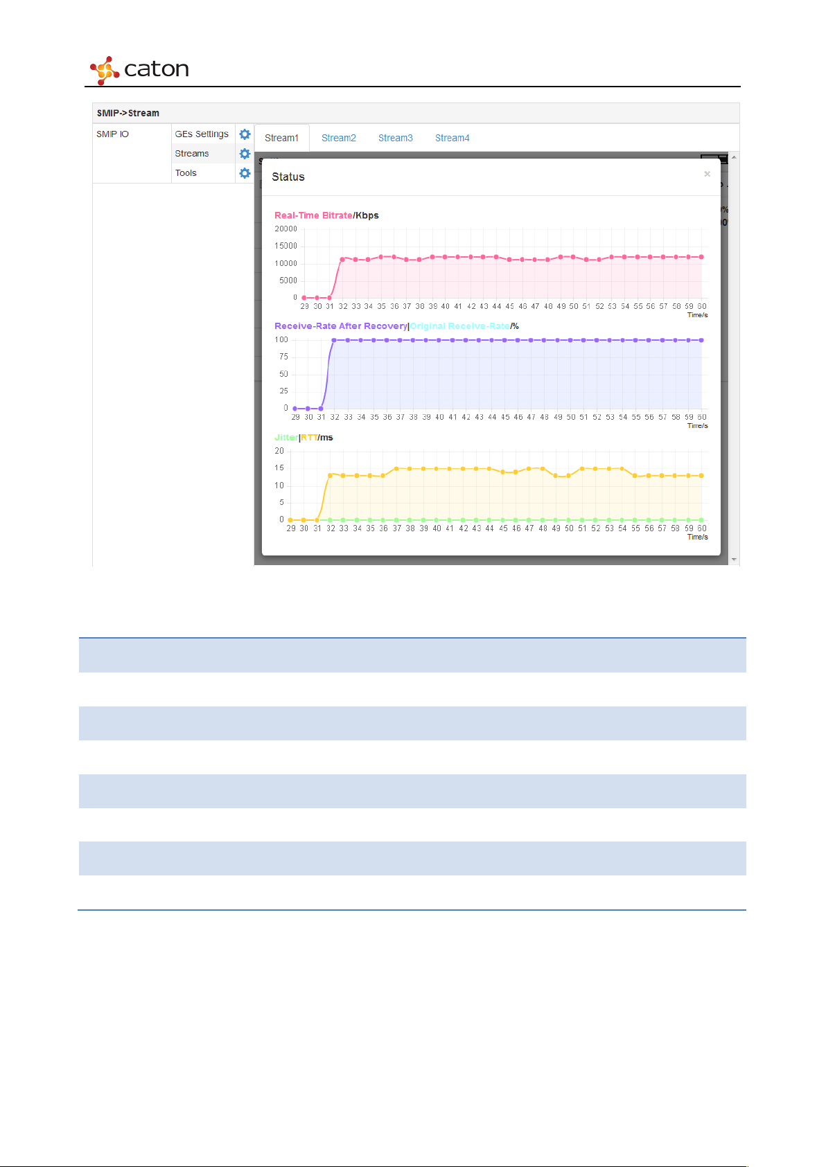
Diagram on the right displays the real-time receiving bit rate of RX, click the diagram to view the
detailed status statistics, as follows:
Page 70
Web Control
Receiving Status
Status
Uptime
Disconnected
Bitrate (Kbps)
ORR (%)
RRAR (%)
Jitter (ms)
RTT (ms)
Figure 5.51 Receiving Status
Green icon: the link is connected; Red icon: the link is disconnected
The duration time of current connection
The disconnected time of current connection
Real-time receiving bit rate of RX
Original receiving ratio of current connection
Receiving ratio after recovery of current connection
The difference value of transmission delay between adjacent packets
Round trip time between TX and target RX
5.6.3 Ping Tools
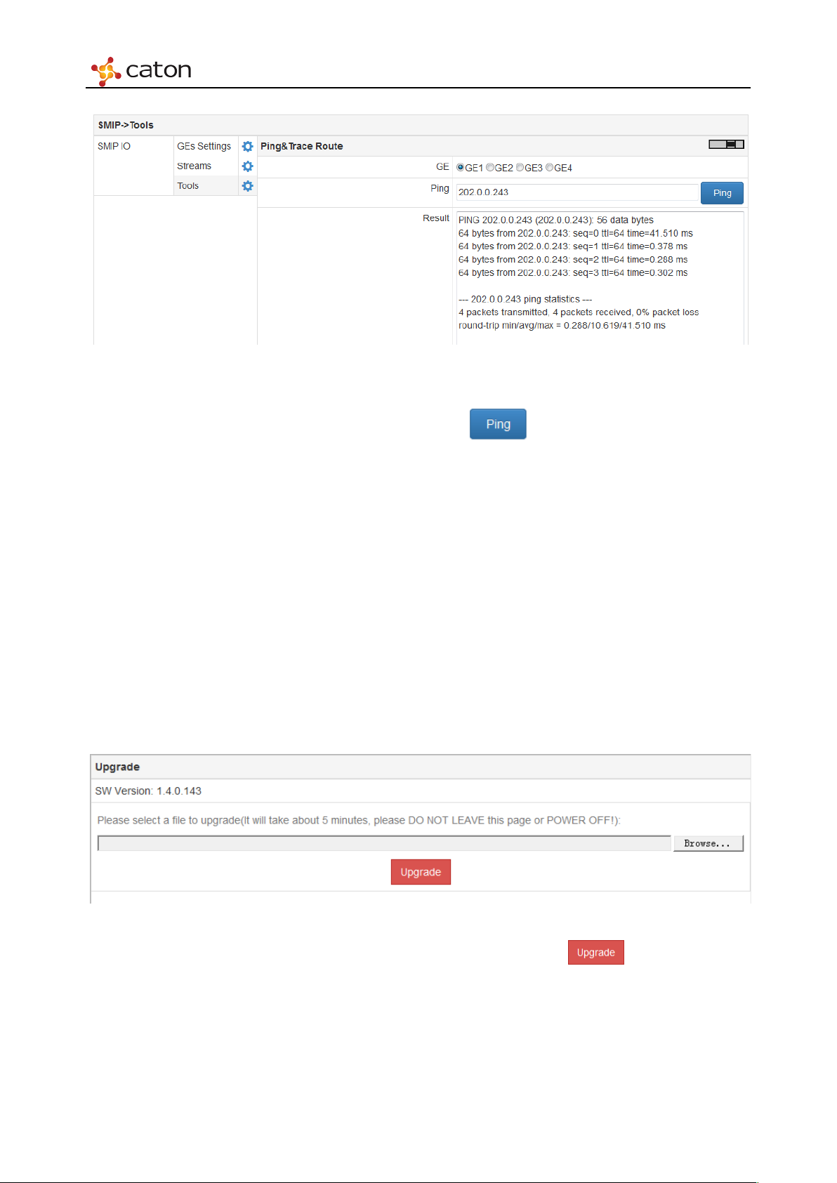
Click Tools to open the Ping & Trace Route page, as follows:
Page 71
Web Control
Figure 5.52 Ping Tools
Use the ping tools to check the connection status between stream port and target IP address.
Select the stream port and input target IP address, click to get the result.
If the result displays “ping fail”, it means the link between stream port and target IP address is
not connected, please make sure the status of stream port is “online”.
5.6.4 Software Upgrade
The steps to upgrade SMIP software are as follows:
Step 1. Connect one stream port (GE1/GE2) to PC by network cable. Make sure the network
link between stream port and PC is connected.
Step 2. Launch the web browser in PC and input IP address of the stream port to open the SMIP
upgrade page, as follows:
Figure 5.53 SMIP Upgrade
Click Browse to select upgrade package in PC and click to upgrade. The
upgrade will take about 5 minutes, please do not leave this page or power off.
Step 3. Connect the other stream port (GE3/GE4) to PC by network cable and upgrade it to the
same software version.
Page 72
Web Control
5.7 Output Setting
Click Outputs in main menu to open the Output Setting page.
5.7.1 IPASI Output I/O Module (IO-IPASI-O)
Click in IP Out*2 ASI Out*2 bar to configure output settings of IO-IPASO-O module.
IO-IPASO-O support IP output by 2 Ethernet ports, and ASI output by 2 channels.
Click in Stream1&2 bar to configure IP output.
Click in ASI Out1/2 bar to configure ASI output.
5.7.1.1 IP settings
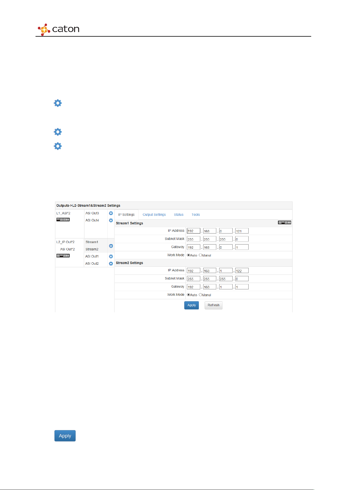
Select IP Settings column to configure network settings of each IP stream Ethernet ports.
Figure 5.54 IP settings
IP Address: Ethernet port IP address setting.
Subnet Mask: Ethernet port netmask setting.
Gateway: Ethernet port gateway setting.
Work Mode: Ethernet port IP address mode setting: Auto or Manual.
In Auto mode, Ethernet speed and duplex mode will be configured automatically.
In Manual mode, Ethernet speed and duplex mode will be configured by user.
Click to save the configuration.
Page 73
Web Control
OFF
Port
1025~65535
Destination IP port
RTP
Service
——
Service ID to output
Click to refresh current page.
5.7.1.2 Output Settings
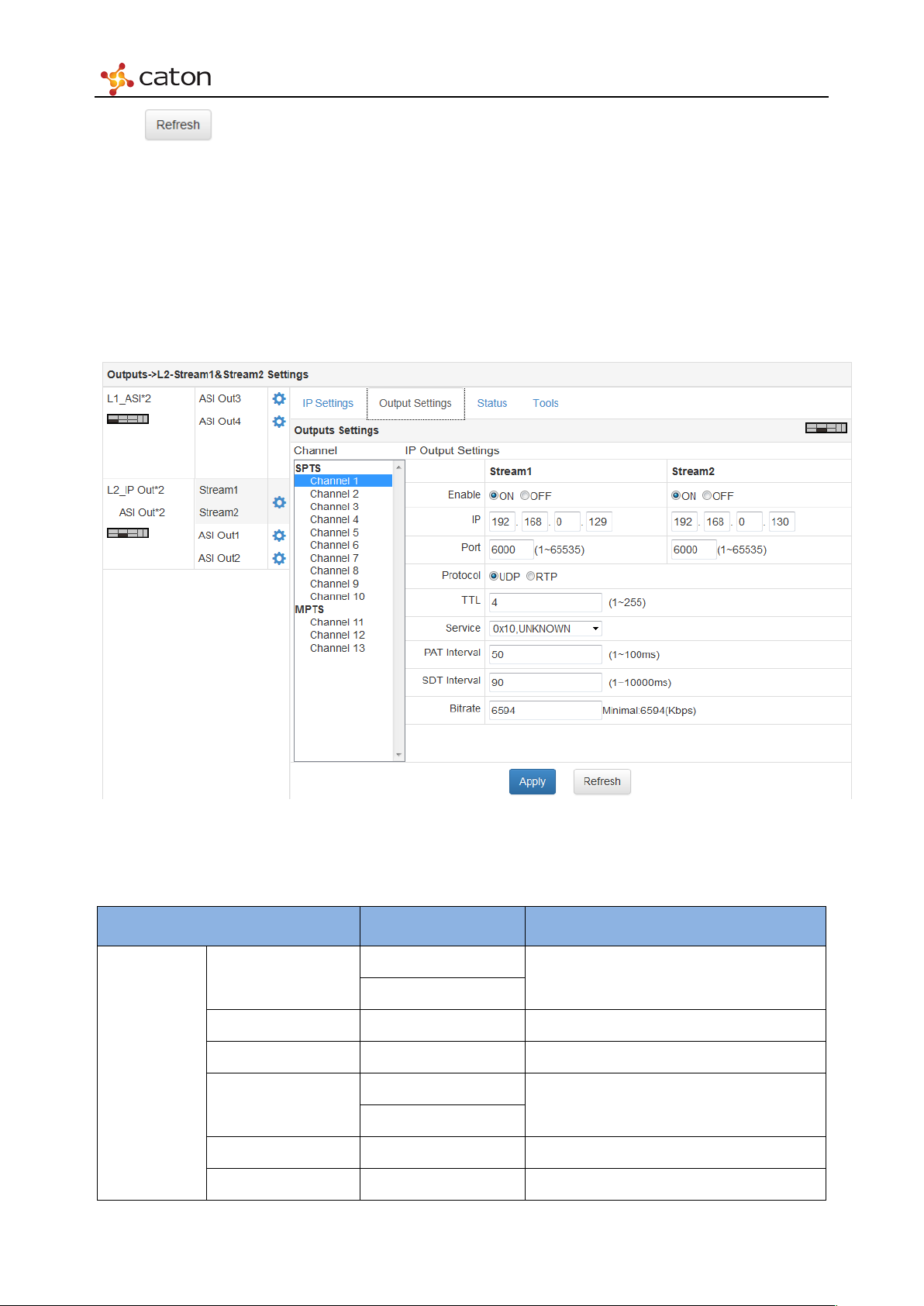
Select Output Settings column to configure IP output streams. 10 SPTS channels and 3 MPTS
channels can be configured independently, and each channel support 2 streams output to 2
different target address by different Ethernet port.
Output
Settings
Figure 5.55 Output Settings
Ta bl e 5.14 Output Settings Parameters
Item Option Comment
ON
Enable
IP <Custom> Destination IP address
UDP
Protocol
TTL 1~255 Time to Live
Enable using the current Ethernet port
Tra nsport P rotocol
Page 74
Web Control
SDT Interval
1~10000ms
PA T I n t e r v a l 1~100ms
Bitrate —— Greater than the bitrate of selected service
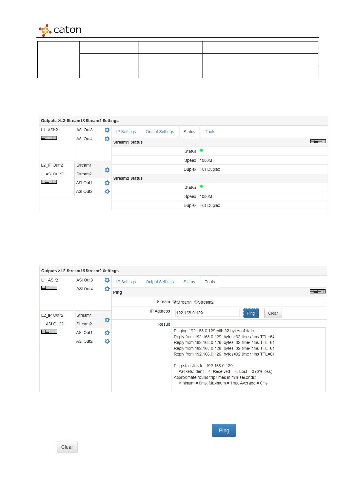
5.7.1.3 Status
Select Status column to view the status of each IP stream port.
Figure 5.56 Status of the stream page
5.7.1.4 Tools
Click Tools to use the network ping tools.
Use the ping tools to check the connection status between stream port and destination IP address.
Select the stream port and input destination IP address, click to get the result.
Click to reset the target IP address.
Figure 5.57 Too ls
Page 75
Web Control
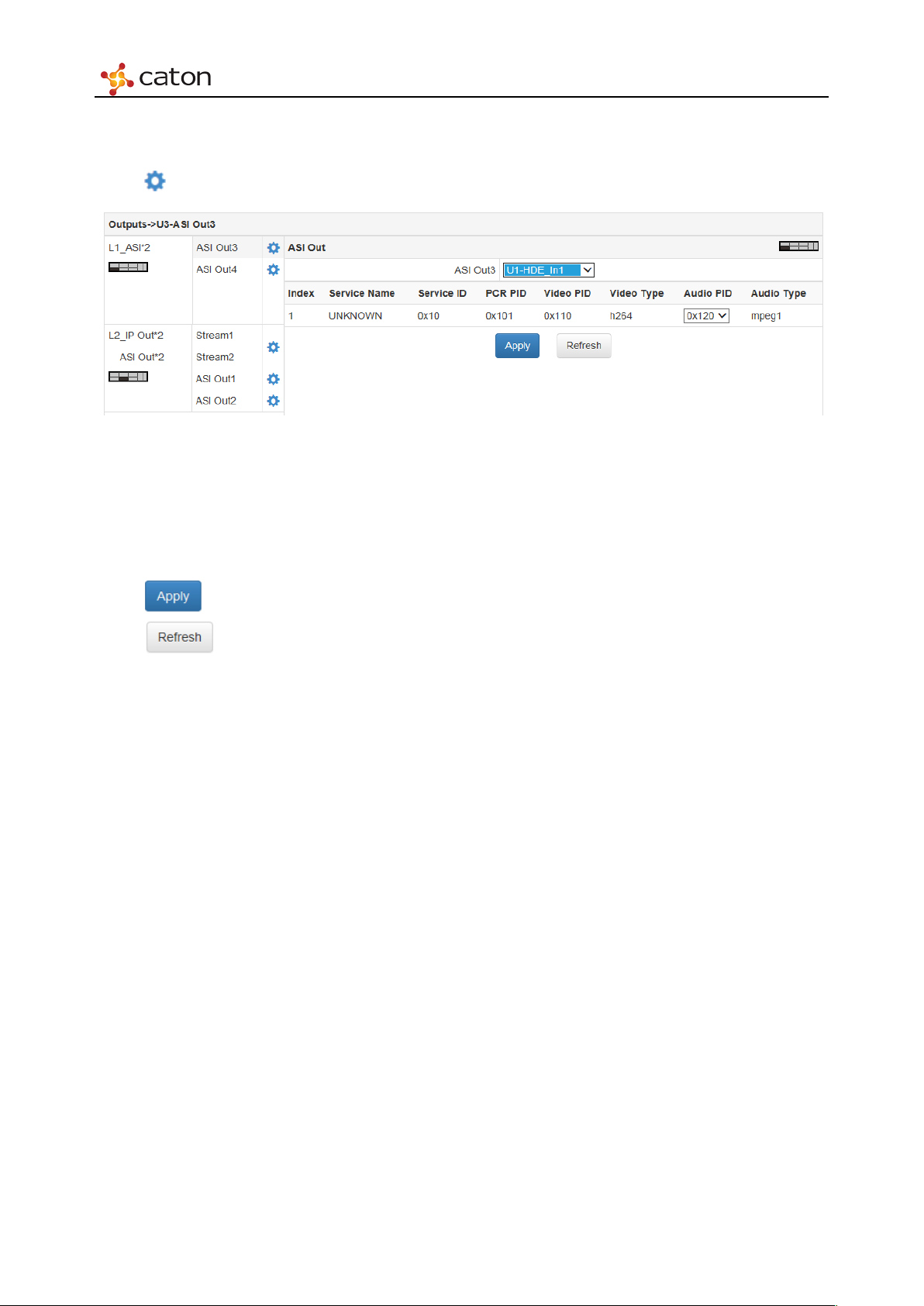
5.7.2 ASI I/O Module
Click in ASI Out1/2/3/4 bar to configure ASI output.
Figure 5.58 ASI Output
In ASI Out Column, user can select the source in IVP-3000 to output via current ASI channel.
After the source is selected, user can view the AV info of the source.
Click to save the configuration.
Click to refresh current page.
Page 76
Web Control
5.8 Alarm
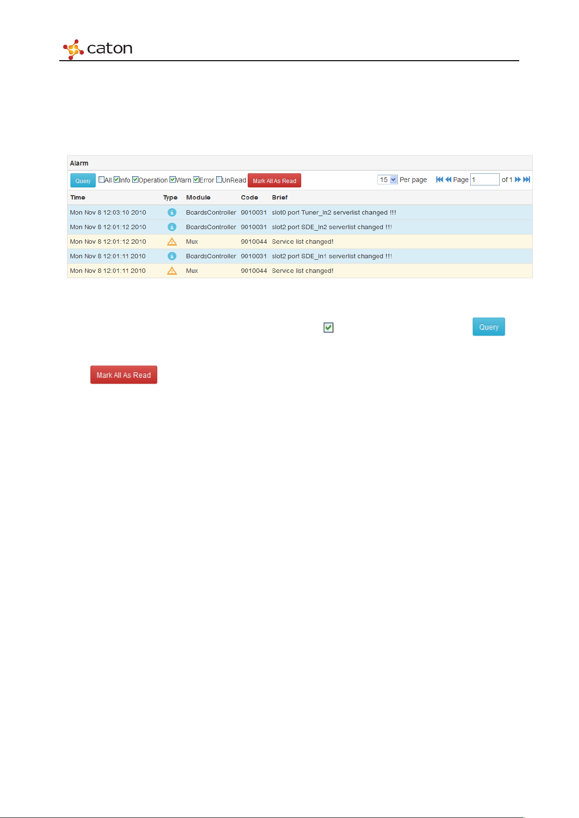
Click Alarm in main menu to review the detailed alarm info. Please be noted that alarm
information will not be saved, and the message will be lost if the device is power off.
Figure 5.59 Alarm
The alarm info will be listed on time sequence. Click to select the type and click to
view the alarm of these types.
Click to remove current alarm info.
Page 77

Annex
Annex A - Specifications
Module
422 HD Digital Encoder Module (HDE-422) 420 HD Digital Encoder Module (HDE-420)
Video Encoding
Video input: HD/SD-SDI, HDMI
Video coding: H.264
Resolution: 1080P@25/29.97/30
1080i@50/59.94
720P@50/59.94/60
576i@50, [email protected]
Chroma: 4:2:2, 4:2:0
Latency: regular: 800ms
low: 120ms
Video bit rate: HD: 2-60Mbps, SD: 0.5-60Mbps
Bit Rate Control: CBR
Entropy: CAVLC, CABAC
Video Loop-Out: HD-SD/SDI
Audio Encoding
Audio input: AES-EBU, SDI Embedded, HDMI Embedded
Audio coding: MPEG-1 layer II, MPEG-4 AAC-LC,
Audio Channel: 4 stereo
Audio mode: Stereo, Mono
Audio bit rate: MPEG-1 layer II: 64-384Kbps
AAC: 64-384Kbps
Support audio loudness automatic control: ITU-R BS.1770
Scrambling
Support BISS-1/E scrambling
Video Encoding
Video input: HD/SD-SDI, HDMI
Video coding: H.264
Resolution: 1080P@25/29.97/30
1080i@50/59.94
720P@50/59.94/60
576i@50, [email protected]
Chroma: 4:2:0
Latency: regular: 800ms
low: 120ms
Video bit rate: HD: 2-60Mbps, SD: 0.5-60Mbps
Bit Rate Control: CBR
Entropy: CAVLC, CABAC
Video Loop-Out: HD-SD/SDI
Audio Encoding
Audio input: AES-EBU, SDI Embedded, HDMI Embedded
Audio coding: MPEG-1 layer II, MPEG-4 AAC-LC,
Audio Channel: 4 stereo
Audio mode: Stereo, Mono
Audio bit rate: MPEG-1 layer II: 64-384Kbps
AAC: 64-384Kbps
Support audio loudness automatic control: ITU-R BS.1770
Scrambling
Support BISS-1/E scrambling
Page 78

Annex
SD Digital/Analog Encoder Module (SDE-420) Multi-Stream HD Digital Encoder Module (MHDE-420)
Video Encoding
Video input: SD-SDI, CVBS
Video coding: H.264, MPEG-2
Resolution: 576i@50, [email protected]/60
Chroma: 4:2:0
Video bit rate: 2 channels: H.264: 250K~6Mbps
MPEG-2: 500K~7Mbps
Bit Rate Control: CBR
Entropy: CAVLC, CABAC
Audio Encoding
Audio input: SDI Embedded, Analog, AES-EBU
Audio coding: MPEG-1 layer II, MPEG-4 AAC-LC,
MPEG-4 HE-AAC, Dolby AC-3 pass-through
Audio mode: Stereo, Mono
Audio bit rate: MPEG1 layer II: 64-384Kbps
AAC: 64-384Kbps
Scrambling
Support BISS-1/E scrambling
Video Encoding
Video input: HD/SD-SDI, HDMI
Video coding: H.264
Resolution: 1080P@50/59.94
1080P@25/29.97
1080i@50/59.94
720P@50/59.94/25
576i@50, [email protected]
Chroma: 4:2:0
Video bit rate: HD: 1-20Mbps, SD: 0.5-20Mbps
Bit Rate Control: CBR, VBR
Video Loop-Out: HD-SD/SDI
Audio Encoding
Audio input: SDI Embedded, HDMI Embedded, Analog
Audio coding: MPEG-1 layer II, MPEG-2 AAC-LC,
Audio Channel: 2 stereo
Audio mode: Stereo, Dual Mono, Mono
Multi-Stream
Support 3 encoding streams output with different bitrates
Scrambling
Support BISS-1/E scrambling
Multi-Channel H.264 Transcoder Module (MHDT-420) ASI I/O Module (IO-ASI)
Video Transcoding
Video input: H.264, MPEG-2
Video output: H.264
Resolution: 1080P@50/50.94
1080P@25/29.97
1080i@25/29.97
720P@50/59.94
576i@25, [email protected]
Chroma: 4:2:0
Audio Transcoding
Audio transcoding: MPEG-1 layer II
MPEG-4 AAC-LC,
MPEG-4 HE-AAC V1
Support various ASI I/O combination pattern:
4 input
3 input and 1 output
2 input and 2 output
1 input and 3 output
4 output
ASI gateway in one unit for channel backup
Support EN-50083-9 standard
Support 188bytes
ASI bit rate: 0~200Mbps for 1 channel
Support Genlock input and loop out
Page 79
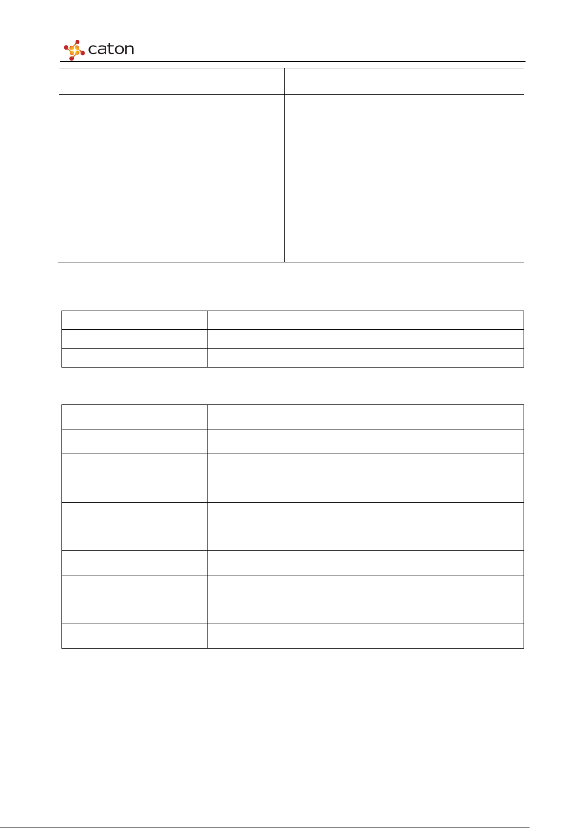
IPASI Output I/O Module (IO-IPASI-O) Multi-Protocol IP Transmitting Module (SMIP)
Annex
Support 2 TS over ASI output
Streaming Port: 2 x 10/100/1000Base-T Ethernet RJ45
Transport Protocol: UDP, RTP
Transport Mode: Unicast, Multicast
Support 10 SPTS over IP output, 3 MPTS over IP output
Each program support output to 2 target address by different
Ethernet ports
Bit rate: IP: 0~600Mbps (Each port)
ASI: 0~200Mbps (Each port)
Support Genlock
Slot in front panel
4x 10/100/1000Base-T Ethernet, RJ45
Each streaming port can be configured as TX or RX
Support Protocol:R2TP, R2TP-S, RTMP, UDP
Max Stream Channel: (Each streaming port)
R2TP/R2TP-S: 2, RTMP: 2
Max Bit Rate: (Each streaming port)
R2TP/R2TP-S: 60Mbps, RTMP: 20Mbps, UDP: 60Mbps
Support DHCP
Support DNS
Control
Front Panel Control OLED screen, touch button
Web Control RJ45
SNMP Control Optional
Physical parameters
Size (W×H×D) 460mm×440mm×44.5mm (1RU)
Weight (Full Loaded) 5.5kg
6 slots in rear panel
Slots
1 slot in front panel
Chassis-R-H: Hot-swap redundancy power supply
Power Mode
Chassis-R: Dual redundancy power supply
Input Voltage 100-240V, 50/60Hz
Consumption
60W
(Full Loaded)
Temperature
0-50℃
 Loading...