

Page 1
11
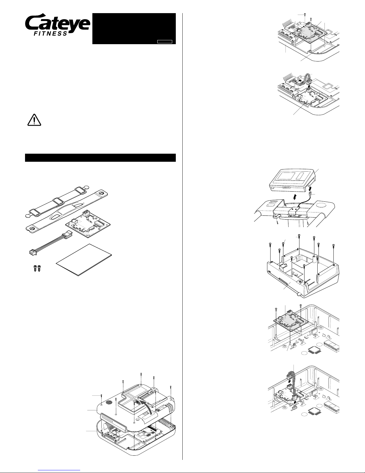
3. Place the circuit board in position to the
right lower corner of the upper body, in
such a way that the cover guide stubs
meet the mating holes provided on the
board, and set it securely with 2 screws
provided in the kit. (Fig.3)
IMPORTANT: Place the circuit board in
the correct way, as shown
in the figure.
4. Connect the newly mounted circuit board
with the adjoining circuit board, using the
connector cable provided in the kit as
shown in Fig.4. To assure positive
connection, insert the cable terminal until a
click sound is heard.
5. Carefully close the upper and lower bodies
and fasten the 8 screws securely.
6. Place the thermal paper in position, and
mount the control unit on your Ergociser
following the EC-1600/3700 operating
instructions.
In case of model EC-5000___________________________________________
1. If the control unit is already mounted
on the Ergocisor, remove it from the
body and pull cable connector, the tip
of 5P cord, out from the cable inlet on
bottom of the control unit, following the
instructions given in Model EC-5000
operating instruction. (Fig.5)
2. Remove 10 screws at the bottom of the
unit and remove the bottom cover.
(Fig.6)
WARNING !:
There is the danger of getting an
electric shock because condenser
etc. are located inside the control
unit. Please be very careful of
touching parts on the board.
3. Place the circuit board in position to
the right lower corner of the upper
body, in such a way that the cover
guide stubs meet the mating holes
provided on the board, and set it
securely with 2 screws provided in the
kit. (Fig.7)
IMPORTANT:
Be careful about the direction of the
circuit board.
4. Connect the newly mounted circuit
board with the adjoining circuit board,
using the connector cable provided in
the kit as shown in Fig.8. To assure
positive connection, insert the cable
terminal unit a click sound is heard.
5. Fix the bottom cover of the unit with 10
screws and assemble the unit.
6. Mount the control unit on your
Ergociser following the EC-5000
operating instructions.
Chest Belt Heart Rate
Sensor Kit
Model TM-1600
Operating Instructions
Introduction
We thank you very much for your purchasing "Chest Belt Heart Rate Sensor Kit" for
use with our Ergociser™.
Using this kit allows you to receive your heart rate via chest strap with EC-1600/EC3700/EC-5000. This kit contains a component to be mounted inside the control unit of
your Ergocisor, so please follow the instructions given below thoroughly before you
start enjoying your training with this kit.
• Pace maker users should never use this device.
• Keep the device away from children. If children use this device,
they should have adult supervision.
• Dispose of used batteries properly. Keep batteries out of the
reach of children. In case the battery is swallowed by accident,
consult a doctor immediately.
PREPARATION
Make sure all the components are included in the kit
• The following parts are included in the package. If anything is missing, please contact
the dealer where you purchesed the kit.
1 Transmitter/Electrode belt
2 Attachment belt
3 Circuit board (receiver)
4 Connector cable
5 Board set screws
6 Instruction manual
Mounting the circuit board in the control unit of Ergocisor
CAUTION !: Please handle the circuit board carefully. Before handling, take an
anti-static measure, such as touching a metallic object, to eliminate
static electricity. Hold only the side of the circuit board.
In the case of models EC-1600/EC-3700 _______________________________
1. If the control unit is already mounted on the Ergocisor, remove it from the handlebar
post, following the instructions given in Model EC-1600/3700 operating instruction.
2. Remove all the 8 screws at the bottom of the unit, and open it slowly. (Fig.2)
CAUTION !: Upper and lower bodies are connected with wirings. Open the
covers carefully not to damage them.
Warning
Copyright© Jan. 2001
CAT EYE Co., Ltd.
TMM16E-010528
066660040 2
screws
Lower body
Upper body
Fig.2
Upper body
Screws
Circuit board
Guide stubs
Fig.3
Connector cable
Circuit board (receiver)
Fig.4
1
2
3
4
5
6
control unit
cable connector
screws
bottom cover
circuit board
connector cable
guide stubs
Fig.5
Fig.6
Fig.7
Fig.8
Page 2
22
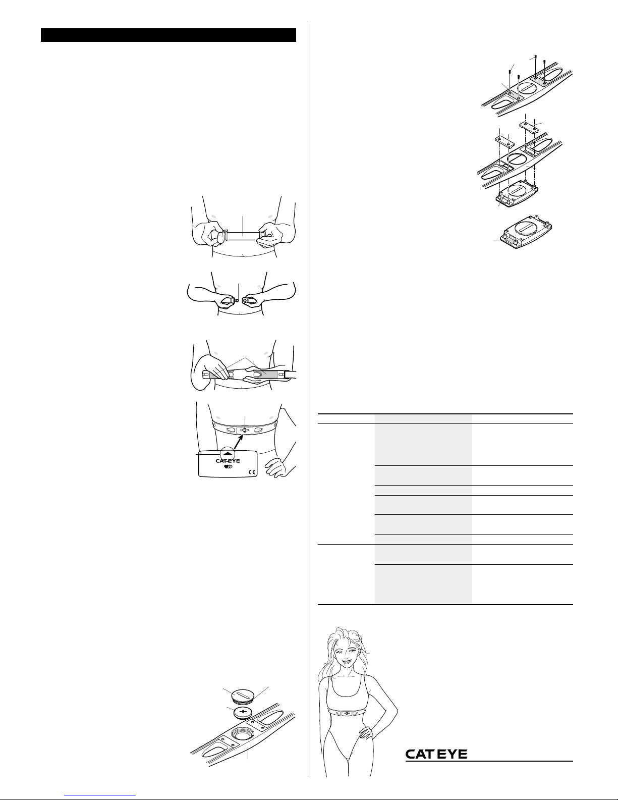
WEARING HEART RATE SENSOR
Before wearing chest belt heart rate sensor
• Wear the chest belt heart rate sensor at the center of your chest and in contact with
your skin.
• To increase measurement effectiveness, dampen the electrode area with water or
electrocardiograph electrolyte cream.
• People with sensitive skin can wear the chest belt over a thin shirt with the electrode
area damped with water.
• Hair on the chest may interfere with accurate measurements.
Wearing the chest belt heart rate sensor
IMPORTANT: When wearing the chest belt heart rate sensor, ensure that the top
mark on the transmitter comes to the top. If worn upside down,
signal’s transmittable distance might become shorter.
1. Adjust the length of the belt to fit your chest.
(Fig.9)
2. Hook the attachment belt to the electrode belt.
Place the electrode area at the center of your
chest. Be sure that the electrode area is held
firmly against your skin. (Fig.10)
REFERENCE:
When wearing the chest belt heart rate sensor
over a shirt it is necessary to moisten the
electrode area for the better results. In the
winter season when skin can be dried, errors
may occur even when the electrodes are in
direct contact with your skin. This can be
improved by moistening the electrodes. (Fig.11)
3. Adjust the belt so that the transmitter is at the
center (just above your diaphragm) of your
chest. (Fig.12)
Wear the chest belt heart rate sensor in the
legible way (the top mark on the transmitter
should come to the top).
Before starting exercise
Be sure to remove the earlobe pulse sensor plug out of the jack of control unit, otherwise the unit does not receive the pulse data.
IMPORTANT: When using the chestbelt sensor, the EC-1600/3700 control unit
will cancel the pitch sound at the pedal speed of 60 rpm, in order to
avoid interference to the pulse data. (When you plug-in the earlobe
sensor, function of pitch sound returns to the normal condition.)
Replacing the battery
When the battery has worn out, replace it with a new one in the following way.
Battery life: approx. 2 years (if worn for 1 hour a day)
CAUTION !: Battery cover seal is critical for maintaining its watertight capacity.
Check the battery cover for proper fit and positioning closing.
NOTE: The chest belt heart rate sensor continues to consume battery while
being attached to your body. When you are not measuring heart
rate, remove it from your chest to save the battery life.
1. Remove the battery cover on the back of the
transmitter with a coin.
2. Replace the old battery with a new lithium
battery (CR2032) with the (+) pole upward as
illustrated.
3. Close the battery cover securely.
Replacing electrode belt
The electrodes on the chest belt naturally wear out after extended use. When there are
cracks on the surface or measurement error occurs, replace the electrode belt with new
one according to the following instruction:
1. Loosen the screws at the back of the transmitter.
(Fig.14)
2. Remove the spacers. Remove the transmitter from
the electrode belt. (Fig.15)
3. Fix the transmitter to a new electrode belt. Clean the
two contacts before assembling. (Fig.16)
IMPORTANT: If the contacts are dirty, the elec-
trodes may fail to detect heart rate.
4. Put the spacers back and fasten the screws securely.
NOTE: When replacing the electrode belt, also check the transmitter's battery life.
Handling care
• Avoid dropping or severely jarring the chest strap.
• Avoid using this unit in dense electromagnetic field, such as near TV or radio set, etc.
• Try to avoid using the main unit within a 1.5m radius of other transmitters. Do not use
other wireless devices simultaneously. It may result in improper measurements.
• Do not use the chest belt if it causes a rash or other skin irritations.
• When the chest belt becomes soiled with sweat, clean it with mild soap and water.
• Do not bend, twist or pull forcibly the electrode area of the chest belt.
• The electrodes may deteriorate and present function error after a long term use.
Replace with a new belt when you notice a sign of deterioration.
Troubleshooting and remedies
The following cases may not represent malfunctions.
Please re-check as suggested below before asking for repair.
Problems Check point Remedy
Pulse rate display
on the control unit
remains 0.
Pulse rate display
turns out 0
intermittenly.
Is the earlobe sensor connected
to control unit?
Is chestbelt placed in correct
position?
Is the belt too loose?
Is the room air too dry? (especially in winter)
Is the chestbelt deteriorated?
Is the battery worn out?
Is the chestbelt placed in correct position?
Does the display turn 0 when
you move away from control
unit, but appear again when you
get closer to the control unit?
Control unit does not accept data
from the chestbelt sensor if earlobe
sensor is connected. Take out earlobe sensor plug from control unit.
Reposition the belt as instructed.
Give the belt an adequate tension.
Wet electrode area a little bit.
Replace the chestbelt with a new
one.
Replace the battery with a new one.
Reposition the belt as instructed.
Battery may be running out. Replace it with a new one.
If the above remedy doesn't help, also check if the circuit boards are positively connected.
Chest belt heart rate sensor
specifications
Maximum transmitting distance: about 70 cm
Operating temperature: 32°F-104°F (0°C - 40°C)
Battery life: abt. 2 years
(When attaching to body 1 hour/day)
Battery: Lithium battery CR2032
Dimensions: 13" x 1-7/16" x 19/32"
(330 x 36 x 15 mm)
Weight: 2.19 oz. (62 g.) including chestbelt
* The specifications and design are subject to change without notice.
2-8-25, Kuwazu, Higashi-Sumiyoshi-ku, Osaka 546-0041 Japan
PHONE: 81-6-6719-7781 FAX: 81-6-6719-2362
CO
.,LTD.
MSC Wireless Heart Rate Sensor
TOP
MSC Wireless Heart Rate Sensor
TOP
CR2032
MSC Wireless Heart Rate Sensor
TOP
Attachment belt
Fig.9
Fig.10
Hook
Fig.11
Electrodes
Fig.12
Transmitter
Top mark
Fig.13
Battery cover
Water proof packing
Heart rate sensor
Lithium battery
Fig.14
Screws
Spacer
Fig.15
Spacer
Electrode belt
Transmitter
Fig.16
Contact
 Loading...