

Page 1
®
STAIR CLIMBER TYPE
Cateye Ergociser
MODEL EC-5000
OPERATING INSTRUCTIONS
EC-5OOO
Page 2

Pulse Symbol
Pulse Rate Graph
GRAPH SCREEN
CONTROL UNIT
Graph Screen
Numeric Screen
Reset Button
Resets the program back to initial state.
Value Adjustment Button
Before exercise
increases or decreases the blinking
number
During exercise
increases or decreases exercise level
After exercise
scrolls back or forth the graph screen
ADV Button
Makes the program proceed to subsequent
stages.
Mode Button
Before exercise
Selects the program and changes the
item to input.
During exercise
Switches the display from total elevation to calorie consumption, and from
exercise level to work rate respectively,
and vice versa.
Card Inlet
Insert the Data Card
Sensor Clip
Keep pulse sensor attached here while not
in use.
NAME OF PARTS
MAIN FRAME
Control Unit
Tray
You can place data cards, drinks, headphone stereo etc.
Pulse Sensor Jack
Insert the pulse sensor plug.
Joint Pipe
Control Unit Cover
Exercise Pattern Number
Program Symbol
AUTO --------------------- Automatic training
INTVL--------------------- Interval training
HILL ----------------------- Hill profile training
MANUAL---------------- Manual training
ORG ----------------------- Original pattern training
Before exercise During exercise
Age-------------------------------------- Pulse rate (bpm)
Upper pulse limit (bpm) ----------- Pedal speed (ft/min)
Exercise level/Target pulse rate - Exercise level/Watts
Weight---------------------------------- Total elevation/Calorie consumption
Target time---------------------------- Elapsed time
EC-5OOO
Pedal Speed Scale
Pedal Speed Graph
Time Scale
NUMERIC SCREEN
Console post fastening bolt
Main Body
Pedals
AC Adapter Inlet
Power Switch
Casters
Handrail Grip
Console Post Cover
Handrail Pipe
Rear Leg
Level Adjuster
Adjustable for uneven floor
2
Page 3

HOW TO USE THIS MANUAL
After you read the Starting up section of this manual, assemble your Cateye
Ergociser™ and try it out. When you get used to the machine and develop a
greater interest in it, please read the Operation section in preparation to trying the machine's numerous functions. Turn to the Reference section whenever the need arises.
TABLE OF CONTENTS
1 ASSEMBLY ---------------------------------------------------------------------------- 6
2 POSTURE AND PEDALING --------------------------------------------------------- 8
3 INSTALLING THE PULSE SENSOR -------------------------------------------------- 9
4 YOUR FIRST STEP ----------------------------------------------------------------- 10
5 THE FIVE PROGRAMS YOU CAN ENJOY --------------------------------------- 12
6 USING YOUR CATEYE STAIR CLIMBER WITHOUT A DATA CARD -------- 14
Starting upOperation
1 TRAINING INDEX AND TERMINOLOGY ----------------------------------------- 18
2 FEATURES OF TRAINING PROGRAMS ------------------------------------------- 20
3 AUTOMATIC TRAINING ----------------------------------------------------------- 22
4 INTERVAL TRAINING -------------------------------------------------------------- 24
5 HILL PROFILE TRAINING--------------------------------------------------------- 26
6 MANUAL TRAINING --------------------------------------------------------------- 28
7 ORIGINAL PATTERN TRAINING ------------------------------------------------- 30
8 HOW TO MAKE A DATA CARD ------------------------------------------------ 32
1 WIRELESS CHESTBELT PULSE SENSOR ----------------------------------------- 36
2 TROUBLE SHOOTING AND HANDLING CARE --------------------------------- 37
3 WARRANTY SERVICE AND OPTIONAL PARTS -------------------------------- 38
4 SPECIFICATIONS -------------------------------------------------------------------- 39
Reference
1
Page 4
INTRODUCTION
Thank you very much for purchasing the Model EC-5000 Stair Climber type Cateye
Ergociser™. The model EC-5000 is a new high-tech stepping exerciser with a built-in
computerized training system designed specifically to promote cardiovascular fitness and
overall endurance, the keystone of good health. With its five training programs, the EC5000 will help you to maintain or improve your physical condition in a fun and pleasant
way. We hope you will make good use of your Cateye Ergociser™ for years to come.
Before using your new exerciser, please read this manual carefully. Then keep it in a safe
place along with the warranty card.
FOR SAFE OPERATION
For safe use, always observe the following rules.
1. Before using the EC-5000, it is important to consult a medical specialist if you are
suffering from any of the following : heart disease (angina pectoris, myocardial infarction), hypertension, diabetes, respiratory disease (asthma, chronic bronchitis, pulmonary emphysema, etc.), articular metamorphosis, rheumatism, gout, or other diseases
and physical complaints. Pregnant women should also consult their doctor before
commencing a training program.
2. If you are not used to regular physical activity, it may be dangerous to suddenly engage
in strenuous activity. Increase your exercise level gradually.
3. If you feel sick or sense something wrong with your body during exercise, stop immediately.
IMPORTANT SAFETY INSTRUCTIONS
Read all instructions before using this exerciser.
DANGER------------- To reduce the risk of electric shock:
1. Always unplug this AC adapter from the electrical outlet immediately after using and before cleaning.
Starting up
1 ASSEMBLY
2 POSTURE AND PEDALING
3 INSTALLING THE PULSE SENSOR
4 YOUR FIRST STEP
5 THE FIVE PROGRAMS YOU CAN ENJOY
6 USING YOUR CATEYE STAIR CLIMBER WITHOUT A DATA CARD
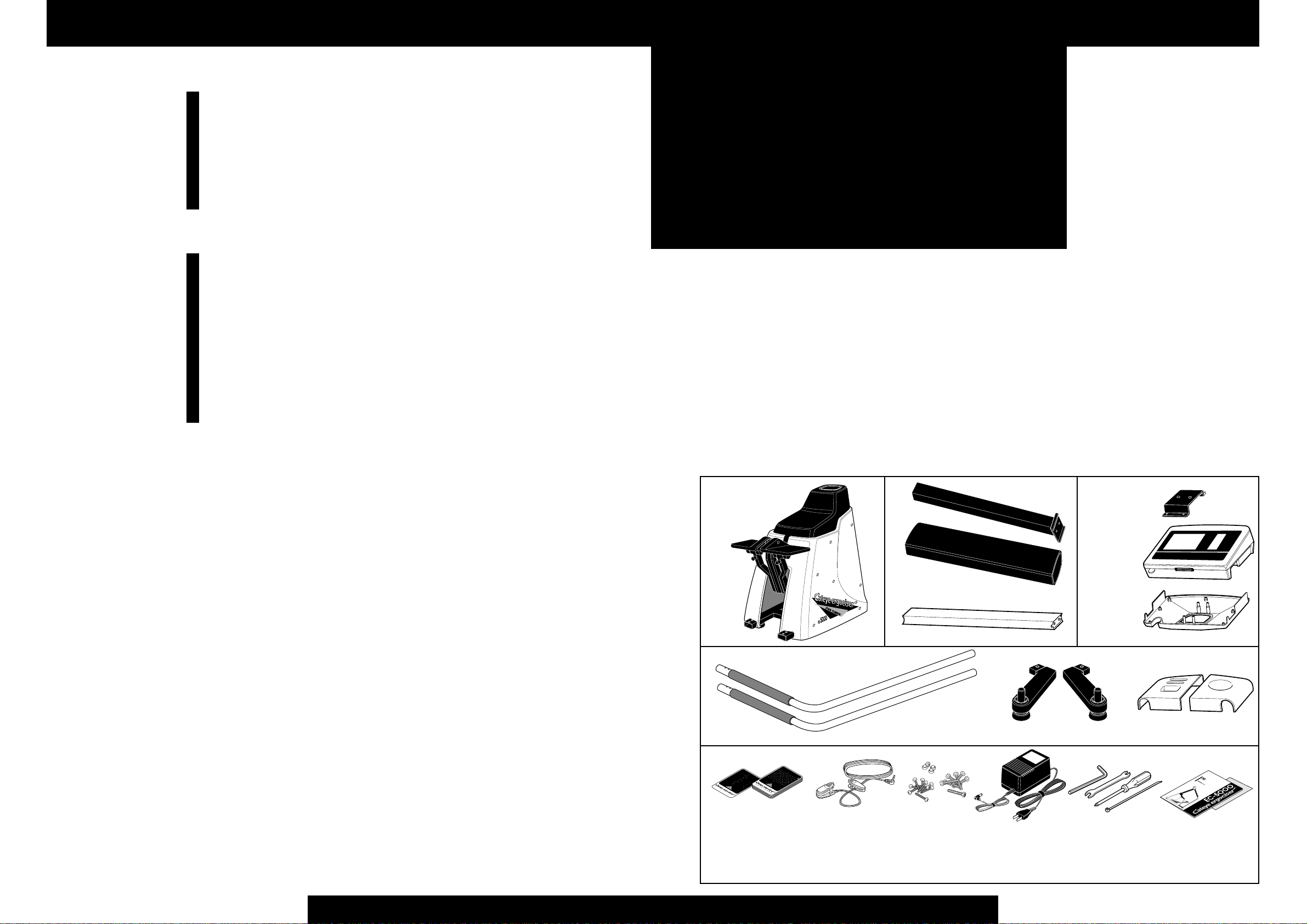
Make sure all components are included in a package.
Console post
Metal fitting
WARNING--------- To reduce the risk of burns, fire, electric shock, or injury to persons:
1. An AC adapter appliance should never be left unattended when plugged in. Unplug from outlet when not in use,
and before putting on or taking of parts.
2. Close supervision is necessary when this exerciser is used by, on, or near children, invalids, or disabled persons.
3. Use this exerciser only for its intended use as described in this manual. Do not use attachments not recommended
by the manufacturer.
4. Never operate this exerciser if it has a damaged cord or plug, if it is not working properly, if it has been dropped or
damaged, or dropped into water. Return the exerciser to a service center for examination and repair.
5. Do not carry this exerciser by supply cord or use cord as a handle.
6. Keep the cord away from heated surface.
7. Never operate the exerciser with the air openings blocked. Keep the air openings free of lint, hair, and the like.
8. Never drop or insert any object into an opening.
9. Do not use outdoors.
10. Do not operate where aerosol (spray) products are being used or where oxygen is being administered.
11. To disconnect, turn all controls to the off position, then remove plug from outlet.
This exerciser is intended for both household and commercial use.
This equipment has been certified to comply with the limits for a Class B computing device, pursuant to Subpart J of
Part 15 of FCC Rules. Only peripherals (computer input/output devices, terminals, printers, etc.) certified to comply
with the Class B limits may be attached to this computer. Operation with non-certified peripherals is likely to result in
interference to radio and TV reception.
SAVE THESE INSTRUCTIONS.
Console post cover
Main body unit
Handrail pipes (2) Rear legs L, R Trays L, R
Data card ------ 10 Pulse sensor Screw set AC Adapter Tool kit Operating Instruction
Start card --------1 •screw bolts ------ 14 •screw driver (this book)
Joint pipe
•tapping screws-- 13 •hexagon wrench Warranty Certificate
•nuts---------------- 4 •spanner wrench
•washer ------------ 2 •cable tie
Control unit
Control unit cover
4
5
Page 5

Starting up
1
1
2
ASSEMBLY
Attaching the rear legs
• Insert the rear legs L and R to the bottom pipe of the main body, and
fasten them securely using the screws and screw driver or spanner
wrench provided.
screw bolt
main body
rear leg
Mounting the console post
• Insert the console post into the main body as illustrated.
Note Watch the front and back of the console post.
• Fasten the cable at the top of the console post using the cable tie.
FRONT
console post
INSERT
cable
console post
5
-2
6
-1
3
-2
4
2
6
-2
6
-1
5
-2
Mounting the handrail pipes
• Place the bottom end of the handrail pipe on the projection of the
5
rear leg , and fasten it with the screw bolts and nuts.
• Connect the top end of the handrail pipe with the joint pipe, and fasten them with the screw bolts.
• Use the hexagon wrench to tighten the console post fastening bolt
securely.
Note When you want to loosen the console post fixing bolt for any
purpose, loosen it only to the necessary extent.
handrail pipe
nut
joint pipe
screw bolt
handrall grip
rear leg
handrail pipe
screw bolt
console post
fastening bolt
TIGHTEN
hexagon
wrench
cable tie
Attaching the console post cover and control unit cover
• Mount the console post cover over the console post.
3
• Place the control unit cover on the console post cover, and fix it into
the console post cover. The cable should come up through the opening of the control unit cover.
console post cover
control unit cover
cable
console post
cover
Attaching the joint pipe
• Mount the joint pipe on the top of the console post cover, attach the
4
metal fitting and fasten it with screws.
• Fasten the control unit cover on the metal fitting, tightening the
screws under the cover.
screw bolt
tapping screw
5
-1
1
5
-3
3
-1
Attaching the control unit
• Place the trays L and R on the joint pipe, and fasten with tapping screw
6
and washer from the bottom.
• Insert the cable connector coming out of the console post cover into the
cable inlet at the back of the control unit.
Note Watch the direction of the cable connector, and be sure to completely insert. If not fully connected, the control unit will not work.
• Place the control unit on the control unit cover, and fasten the 7 screws
from below.
Remark The select switch at the back of the control unit serves to
shift the scale units. At our factory, the unit is set for feet and pound.
No.1: ON ---------meter/kg No.2: ON--------- Japanese
No.1: OFF--------feet/lb No.2: OFF ------- English
cable inlet
select switch
Control unit back view
control unit
cable
connector
joint pipe
metal fitting
1
washer
5
-1
6
tapping screw
7
tray L
tapping screw
tray R
control unit cover
Page 6

Starting up
Starting up
2
POSTURE AND PEDALING
1. The pedal will slowly go down when you step on it. Before the
pedal goes all the way down to the bottom, start pushing the
other pedal rhythmically.
2. Hold the handrail until you get used to the stepping motion.
3. The data display will not be accurate if you lean too much on
the handrail. Either release the handrail or lightly hold it only
occasionally when you get used to the exercise.
4. The faster the climbing speed is, afaster stepping action is required.
Remark You may sometimes fail to catch up to the stepping speed, while you are a beginner. Also the stepping
speed can be decreased by the – button, except in Automatic training, use this button to adjust the stepping speed
to the level that can keep you stepping without dropping
either pedal to the bottom.
3
Your pulse rate is detected from your earlobe by the
pulse sensor provided. Since the pulse sensor is a
delicate electronic part, handle it with sufficient
attention.
INSTALLING THE PULSE SENSOR
Connecting the pulse sensor
• Insert the pulse sensor plug into the sensor jack on the back
of control unit. Always keep the pulse sensor on the sensor
clip of the control unit, when it is not being used.
pulse sensor jack
pulse sensor plug
sensor clip
Adjustment and transportation
• If the floor surface is uneven, turn
the appropriate level adjuster(s) located under the main body and rear
legs until the unit becomes stable.
• To move the unit, lift the rear leg
part and roll the unit on the front
casters.
Using pulse sensor during exercise
When the pulse sensor is correctly attached, the heart symbols
appears blinking on the graph screen as soon as the program
starts, and the pulse rate figure is displayed on the numeric
screen. Note the following:
• Clip the pulse sensor at the center of your right or left earlobe
as illustrated.
• When it is cold, massage your earlobe before use to improve
blood circulation.
• Attach the cable clip to your clothes to prevent excessive
swinging of the sensor cable.
• Ear rings or other ornaments must be removed when attaching the sensor.
• If the pulse rate reading frequently turns to 0, the pulse sensor may be not correctly attached to your earlobe. Remove it
once and reattach it.
• Try not to change the position of the pulse sensor during the
exercise.
• When removing the pulse sensor after exercise, be sure to remove also the cable clip.
Caution The sensor cable can be damaged when pulled or
jerked. Treat it with care, for indefinite use.
pulse (earlobe)
sensor
pulse (earlobe) sensor
pulse (earlobe)
sensor
higher
level adjuster
lower
caster
When the pulse rate display is abnormal
• If the pulse rate display is still irregular even after trying several different attaching positions, the sensor is considered to
be damaged. In such a case, replace the pulse sensor with a
new one (available as spare parts).
level adjuster
8
9
cable clip
Page 7

Starting up
4
123
1
2
3
YOUR FIRST STEP
Connect AC adapter
Turn on power
Attach pulse sensor
Turn on power and attach pulse sensor
• Insert the DC connector of the AC adaptor into the AC adapter inlet at
the rear of the exerciser.
• Insert the AC plug of the AC adaptor into any household AC outlet
(120V).
• Turn on power switch. The control unit should display “WELCOME”
message and prompt you to attach the pulse sensor and to either insert
the data card or to press ADV button.
• Attach the pulse sensor to your either earlobe. When it is cold and the blood
circulation at the earlobe is not active, massage the earlobe for a while.
Caution Do not use any AC adaptor other than the one supplied with
the Model EC-5000.
Insert the start card (yellow card provided)
• Find the yellow card (start card) in the packaging of the exerciser. Insert
this card into the slot of the control unit (card inlet). If the card is reversed, the unit will not work. Be sure to insert as shown in the drawing.
Caution Use only the yellow card at this stage. It is a sample card
with the exercise data already registered in it. The unit will not work
with the black cards since they do not contain any data yet. Refer to
page 32 regarding how to make your own data card.
Checking the screen display
• The graph screen prompts you to press ADV button,
and the numeric screen should be as in the drawing. If
these displays do not appear, pull the card out and
slowly insert it again. The numbers in the display represent training conditions.
1 "HILL" which is short for "hill profile training"
shows the type of training to be engaged in. The
pedal speed will automatically change according to
the hill shape.
2 "1" indicates the shape of the hill to be climbed.
"1" is the gentlest slope.
3 The figure "50" shows the Age.
4 "150" is the upper pulse rate limit, automatically set by the machine (200 –
age). If this pulse rate is exceeded while training, an alarm will sound and
the pedal speed will become the minimum.
5 “-5-” (level) means the exercise intensity. 5 is standard, and it’s adjustable from
1 (easiest) to 9 (hardest). The difference from one level to the next is about 6%.
6 160 is for body weight in pounds. This value is used in the calculation of
calorie consumption.
7 Exercise time is shown by "15:00", which means 15 minutes.
8 The lower part of the graph screen shows the changes of pedal speed in this
program.
9 The upper part of the graph screen shows the message for next procedure.
Remark The data on the screen can be revised at this stage. For instance,
the + – buttons will raise or lower any of the above numbers. The MODE
button will shift the items to adjust. However, the purpose of this section is
to get you acquainted with EC-5000, so if you change any of the numerical
values, please return them to their original setting.
Insert start card
Review displays on the
screens
power switch
start card
Adjusting numerical values
Shifting items to adjust
AC adapter inlet
DC connector
card inlet
Press ADV button
(Start of the exercise)
456
Start stepping
Press ADV button to start
• Press ADV button.
4
• A short buzzer beeps, and the message as “HILL
START” blinks several seconds on the graph screen,
to announce the start of a Hill Profile training.
• Start stepping slowly. As time goes on, the descending
speed of the pedal will gradually become faster. Begin
stepping the other pedal before one pedal goes all the
way down.
• The numeric and graph screens will show such data as
in the drawing. The numbers on this screen represent
your current condition, which will keep changing with
the lapse of time.
1 Heartbeats per minute.
2 Pedal speed represented by feet per minute.
3 Exercise level at present. Adjustable by +-buttons during the session, if you
wish.
4 Accumulated height (feet) you have climbed since the start of exercise.
5 Elapsed time after starting the current session.
6 The graph screen shows the changes of your pulse rate in the upper part,
and the pedal speed in the lower part. The dot column of the current time
frame is blinking. As time goes on, the blinking row in the graphic part will
shift one by one toward the right hand. According to the position of the
blinking row you can find how far you have progressed in the current session. The graphic display can be recalled after the exercise, though a part of
it is once rolled out of the screen.
Calorie/Watts display
• Pushing MODE button gives you the option of viewing the work rate in watts
5
(how much power you are generating) and calorie consumption (kcal), instead
of exercise level and total elevation respectively.
• Just keep on pedaling for a while. As you continue, pedal speed will change,
energy expenditure will change, and your pulse rate will also change. The
Model EC-5000 lets you keep track of all such information while you exercise.
Finish of exercise
• When 15 minutes have elapsed, a buzzer will sound and the session will auto-
6
matically finish.
• You can also stop exercise before completing 15 minutes, by pressing ADV
button.
• The display on the screen will remain even after finishing the exercise. At this
stage, you can review the changes of pedal speed and your pulse rate throughout the whole session.
• Press RESET button and the program completely ends, and the screen turns to
the initial state of “WELCOME” message.
The description up to this point is only the beginning of the Model EC-5000 Cateye
Stair Climber functions. Let us move on to an explanation of other functions.
10
Press MODE button
(Switching displays)
11
Press ADV button
(Finishing the exercise)
Press RESET button
(End of entire program)
Start Training
Switching display items
Finishing the exercise half way
Complete end of the program
Page 8
Starting up
5
THE FIVE PROGRAMS YOU CAN ENJOY
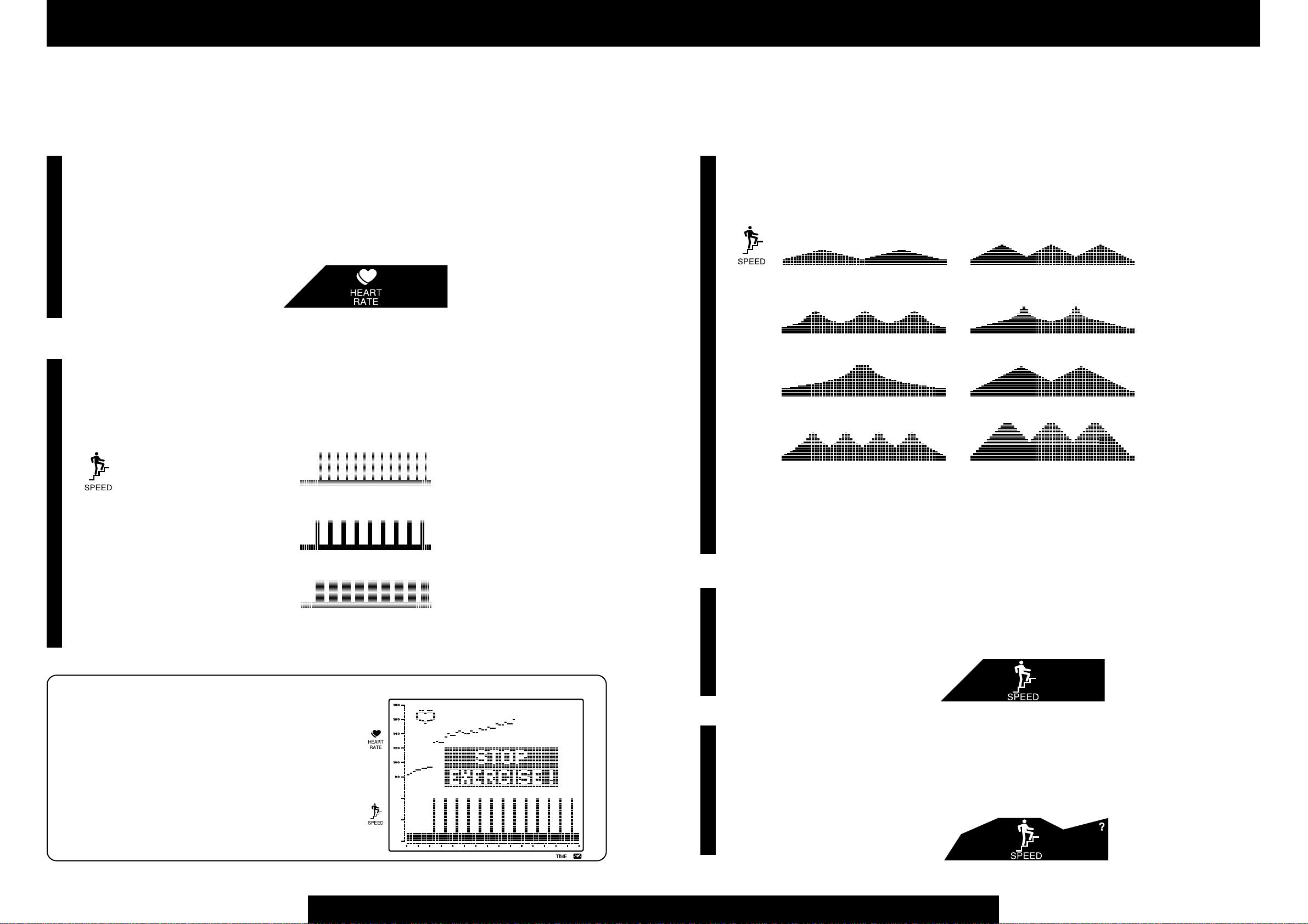
Automatic training (= Target Heart Rate training)
• You set a target pulse rate at which you want to exercise and the Model EC5000 automatically adjusts pedal speed to maintain your pulse rate close to the
desired level. This is ideal for effective aerobic training.
• As you repeat the exercise at a certain pulse rate and make progress in your
fitness level, you will be able to create a greater work amount under the same
pulse rate. Consequently, you will be able to exercise at a higher target pulse
rate.
Interval training
• By switching back and forth between exercise and relief periods of varying
length, interval training gives you the kind of program that serious athletes
often use to build up their total power.
• On the model EC-5000, 3 patterns of interval training programs are available
for developing sprint power, speed, and endurance respectively.
PRF-1: dash strength training
(sprint power)
15 seconds exercise followed by a 45 second relief.
PRF-2: speed training
(anaerobic power)
30 seconds of exercise followed by a 60 second relief.
PRF-3: endurance training
(aerobic power)
60 seconds of exercise followed by a 30 second relief.
• Choose one of the above patterns, and adjust the intensity by specifying one of
the 9 levels.
AUTO
(A training at a constant pulse rate)
INTVL
(repetition of exercise/relief pattern,
tailored for professionals)
Hill profile training
• Pedal speed changes to simulate the effect of climbing up and down on the
mountains. The changing patterns of pedal speed are shown on the screen.
• The following eight types of mountain profiles are programmed.
PRF-1: the Apennines PRF-2: the Appalachian
PRF-3: the Cascades PRF-4: the Pyrenees
PRF-5: Mount Fuji PRF-6: the Rockies
PRF-7: the Alps PRF-8: the Himalayas
• The mountain profiles from 1 to 8 are arranged in order of difficulty. Try to
start with a profile that looks easy enough for you.
• The preset training time is 15 minutes. If you set a longer training time, the
number of peaks will not change but the overall hill shape will be extended out
in proportion with the time.
Manual training
• You designate the pedal speed (ft/min.) among the 20 exercise levels preset in
the computer, and it stays constant regardless of your pulse rate or pedal pitch.
This is the basic, traditional way the stair climbers have been utilized.
Setting range: Level 1 to 20
HILL
(casual exercise of hill climb feeling)
MANUAL
(training at desired pedal speed)
Upper Pulse Limit Alarm
• For your safety, the upper pulse limit alarm is provided in all
the programs of the EC-5000. If your pulse rate exceeds this
limit, the screen will display a message as “STOP EXERCISE!” for 10 seconds, the alarm buzzer beeps and the pedal
speed automatically drops to the minimum.
• If this alarm is activated, the program is suspended at that
point, and you cannot continue the program any more.
12
Original Pattern training
• You can create an original hill profile pattern. You can enjoy a unique exercise
unlike the conventional routines.
• The operation of this program is similar to that of Hill Profile training.
13
ORG
(exercise designed by yourself)
Page 9

Starting up
6
The yellow card you used on your first ride
serves to input the type and condition of
training. But it is also possible to complete
the same procedure without the card, but
using the buttons on the control unit.
1
2
USING YOUR CATEYE STAIR CLIMBER WITHOUT A DATA CARD
Connect AC adapter
Turn on power
12
Attach pulse sensor
Press ADV button
Turn on power supply
• Plug in the AC adaptor and turn on the switch at the front of the main body.
• The screen shows "WELCOME" with the picture of pulse sensor, urging
you to attach the pulse sensor to your earlobe and to either insert a data
card or press ADV button.
• Attach the pulse sensor to your earlobe and press ADV button.
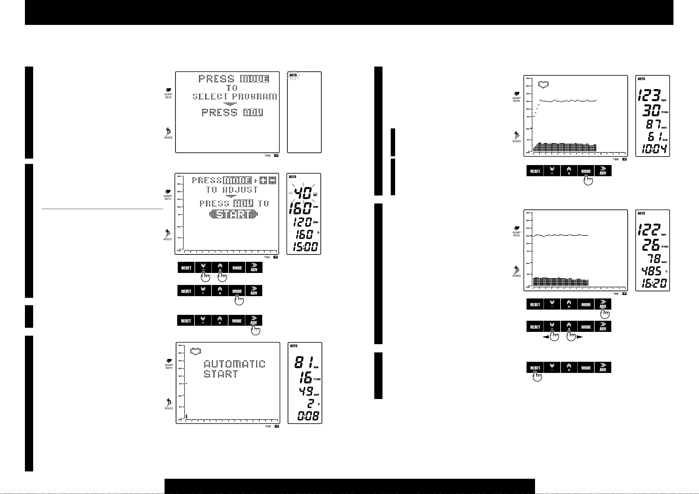
Select a training program
• The graph screen prompts you to select a training program.
• With each press of the MODE button, the program symbol shifts from
one to another in the following order, in the numeric screen.
AUTO Automatic training
INTVL Interval training
HILL Hill profile training
MANUAL Manual training
Press MODE button
(Select program)
Press ADV button
(Enter program)
Adjust age by + – buttons
Press MODE button
(Shift items to adjust. Set target pulse
345
rate, weight and exercise time through
the same procedure)
• Press ADV button to start the program. The
graph screen displays blinking letters as “AUTO
4
START” to announce that the Automatic training program has now started.
• Start stepping the pedals slowly. As time goes
on, the descending speed of the pedals will increase gradually. Step down the other pedal before one fully drops to the bottom.
• The pedal speed is automatically adjusted to
keep your pulse rate close to the target.
• By pressing the MODE button during the exercise, the display is switched from total elevation
(feet) to calorie consumption (Kcal), and viceversa.
Starting the exercise
Press ADV button
(Start program)
Start stepping
Use MODE button to
switch display data
Press ADV button
(Finish exercise)
Press RESET button
(End of program)
Elevation
ORG Original training
• You already tried the hill profile training. This time let’s choose
"AUTO" (Automatic training) as example.
• Press the MODE button until "AUTO" blinks, then press ADV to lock
in your choice.
Input training conditions
• The graph screen prompts you to set the training
3
conditions.
• The screen changes as shown here, with the number "40" blinking.
• You can raise or lower the blinking number by pressing + or – button. The value changes rapidly if either
button is held down. For example, press + button to
change the number for age from 40 to 52. As you revise the age, the setting of upper pulse limit and target
pulse rate will be automatically revised.
• With each press of the button, the blinking items
shift from one to another in the following order.
Note Do not revise the upper pulse limit, because
it is automatically set when you input your age.
Remark Conditions to input vary depending on programs.
• Let's try changing the displayed target pulse rate from 108 to 115.
• Press MODE button until "108" blinks. You want to reduce the number by
seven, so press the + button seven times.
• You can revise the value for weight, according to your body weight.
• The exercise time is also changeable.
Remark The card is a tool to instantly set a program and training
conditions. Usually you have to set such conditions by press buttons
before each session, but the data card saves you such a trouble.
Start training
14
Entering program choice
Upper limit pulse
Target pulse rate
Adjusting numerical values
Shifting items
to adjust
AGE
rate
Weight
Target time
AGE
Upper limit pulse rate
Target pulse rate
Weight
Target time
Switching the display
Finish of exercise
• A buzzer will sound when the exercise time you set
5
has elapsed. If you wish, you can continue training
even after this buzzer sounds.
• Whenever you want to finish the exercise, before or
after the buzzer sounds, press the ADV button.
• The pedal speed drops to the minimum and the program comes to the end. If you’d like to cool down,
keep pedaling slowly. Under such state, the numeric screen still keeps monitoring your pulse rate,
and such data as pedal speed, total elevation, or
calorie consumption is updated from time to time.
• After the exercise you can review your workout
data on the graph screen. If you have worked more than 15
minutes, you can use +– buttons to recall the data of the
past time frames. The – button will scroll the screen to the
left and the + button to the right hand.
• Press RESET button and the program completely ends,
and the display turns to the initial state with the “WELCOME” message.
For further details of this product, proceed to the “OPERA-
TION” section when you get accustomed to using this unit.
Calorie Consumption
Finishing the exercise
Scrolling the graph display
Complete end of program
15
Page 10

Operation
1 TRAINING INDEX AND TERMINOLOGY
2 SUMMARY OF EACH PROGRAM
3 AUTOMATIC TRAINING
4 INTERVAL TRAINING
5 HILL PROFILE TRAINING
6 MANUAL TRAINING
7 ORIGINAL PATTERN TRAINING
8 HOW TO MAKE A DATA CARD
Page 11

Operation
1
TRAINING INDEX AND TERMINOLOGY
Purpose of Exercise
• Don't you feel out of breath after climbing a flight of stairs or after a brisk walk?
While walking, running and even sleeping, our body is taking in oxygen and generating energy . Oxygen taken in by the lungs is sent to the entire body via the circulatory
system. If the function of the circulatory system , i.e. aerobic power , is insufficient, we
may experience being "out of breath" or experience yet other physical problems.
• We therefore perform "health for the heart" (aerobic exercise), which causes the
heart to work a little more a few times a week, thus increasing the oxygen supply to
the body via the circulatory system. The purpose of exercise with the Ergociser is to
improve both your physical condition and the functioning of the circulatory system:
to improve our aerobic power .
Exercise Plan
• To effectively perform "health for the heart" it is necessary to find out the appropriate target pulse rate for your age and fitness level, and to continue the exercise at the
pulse rate close to such a target. If the exercise intensity is beyond your current fitness level, you may damage your health, and below your target rate you may not
receive any improvement.
• The Ergociser EC-5000 has the Automatic (= target heart rate) training mode, in
which the pedal speed is adjusted by the computer to keep your pulse rate close to
your target, plus 4 different types of exercise modes.
How to decide your target pulse rate
When you input your age, the EC-5000 automatically sets your target pulse rate at
[160–age]. This target pulse rate corresponds to 50-60 % of the exercise level for the
twenties, 40-50 % for the sixties. (Refer to "Exercise Level" on page 19.) The older
you are, at the less intense level your target pulse rate is set because of such programming of the EC-5000. The exercise level automatically set by this unit could be
too hard even for a young person, if he is a beginner . If you feel it too hard, you may
decrease the target pulse rate by 10 bpm from the original level. If you feel too easy ,
you may increase it by 10 bpm so that you can continue exercise in the appropriate
target zone as illustrated. If you can continue your exercise at the target pulse rate
of [180–age], your exercise can be considered as effective enough. Upgrade your
exercise gradually so that you can reach the suggested final target of [190–age].
Exercise Time for Each Session
A minimum of 30 minutes exercise is necessary for each session of exercise. A 5 minute warm up period, and
20 minutes of exercise time, with a 5 minute cool down period, is suggested as a standard exercise. For weight
reducing exercise, over 30 minutes exercise time at the low level of the target pulse rate is recommended with
a 5 minute cool down.
How many days a week for exercise
Minimum two exercise days a week is required just to maintain your present fitness level. With 3-4 exercise
days you can expect improvement. Always consult with your doctor before proceeding with any exercise
program.
Caution Concentrated and repeated exercise in a day may produce an adverse result.
For a person who has built up enough physical strength
The setting limit of the target pulse rate is (Upper pulse limit–10), but if you wish to exercise at a higher
target, you can first modify the Upper pulse limit and then input the target pulse rate. The maximum settable
Upper pulse limit is 199, so you can set the target pulse rate to 189 bpm at maximum. In case you raise the
upper pulse limit beyond the automatic setting, be careful with your physical conditions while you exercise.
Terminology
Maximum Heart Rate
The heart rate increases according to the intensity of exercise, there is however
a limit. The maximum heart rate that a person can sustain is called the "maximum heart rate". Generally the heart rate declines as we get older , this differs
however between individuals, and is largely due to how much one exercises.
Difference Between the Heart Rate and Pulse Rate
The heart rate is the rate of the heart beat per minute measured by an electrocardiograph. On the other hand, the pulse rate is measured as follows.
1) By palpating an artery near the skin surface, such as the carotid artery, measure the pulse count of a blood vessel.
2) Transmit a sensor light to an earlobe or finger tip, and measure the pulse
count via the subtle changes of the sensor light transmission caused by the
heart beat.
Although the measurement principle and method are different, both the heart
and pulse rates have the same value per minute, and are therefore regarded as
synonymous.
Since earlobes move very little during exercise and are not influenced very
much by physical movement, it is appropriate to use an earlobe to measure the
pulse rate during exercise. The Ergociser EC-5000 therefore measures the
pulse rate by detecting changes in the circulation of the earlobe.
Pulse Limit
As a standard maximum heart rate, "220–Age", "204–0.69 x Age", etc. are
used. In this EC-5000, however, "200-Age" is adopted taking into account a
certain safety margin, and incorporated in the computer setting. This setting
can be revised upward when desired, though it should be done prudently.
Target Pulse Rate
The pulse rate you should maintain during the workout is called the "target
pulse rate". The "Automatic training" allows you to stay close to this target,
but you are recommended to always be conscious of your pulse rate even when
performing different types of training programs, referring to the "T arget Pulse
Rate Chart" shown on the left. The maximum settable value is "Upper pulse
limit - 10".
Exercise Level Based on the Pulse Rate
The pulse rate increases according to the intensity of the exercise. In other
words, the pulse rate during exercise is a barometer for the exercise level. The
exercise level can be determined in percentages by the following formula.
Exercise Level (%) = x 100
Therefore, if you want to discern the target of the exercise level from the pulse
rate (target pulse rate), you can calculate as follows.
Target pulse rate = (maximum heart rate – pulse rate at rest)
Note The "Exercise level" mentioned above represents a different
concept from the exercise level that you select when inputting the exercise conditions in the EC-5000.
Pulse rate during exercise – Pulse rate at rest
Maximum heart rate – Pulse rate at rest
Exercise Level (%)
x + pulse rate at rest
100
16
17
Page 12

Operation
2
FEATURES OF TRAINING PROGRAMS
Automatic Training
• In this program, the exercise intensity is set by your target
pulse rate (beats per minute: bpm). Select your target pulse
AUTO
rate at a lower level as shown in the target zone according to
your age.
• If the target you select is difficult to achieve, reduce the target
pulse rate by 10 bpm, and continue.
• You can increase your target in 10 bpm units, referring to the
target zone in the illustration on pages 18 and 19.
• The exercise duration is initially set at 15 minutes, but you can
change it in the range from 1 to 99 minutes. One calibration
on the time axis on the graphic screen will remain at 15 seconds, and the screen will scroll when exceeding 15 minutes.
• Exercise per training should be for at least 15 minute. If possible, a 20 to 30 minute
exercise is even better .
• If weight control (calorie expenditure) is the purpose of the exercise, set the target
pulse rate lower so that you can easily exercise even while watching TV, but extend
your exercise time longer , in this case exceeding 30 minutes.
Interval Training
• In this program, select one of the 3 patterns that suits your
needs.
INTVL
• This program is for the trained people with a long career of
exercise.
• You can adjust the training intensity in 9 exercise levels. The
standard level is 5, and you can change the level in the range
from 1 (easy) to 9 (hard). One level is equivalent to 6% increment or decrease, and max. 25% increment or decrease is
possible against the standard level.
• The pedal speed should be such that you have to step quickly
while you are exercising, and step slowly while you are at a
rest.
• Exercise per training should be for at least 15 minute. If possible, a 20 to 30 minute
exercise is even better .
• The exercise duration is initially set at 15 minutes, but you can change it in the range
from 1 to 99 minutes. One calibration on the time axis on the graphic screen will
remain at 15 seconds, and the screen will scroll when exceeding 15 minutes.
• Depending on the physical fitness level and purpose, some people may exercise at a
higher pulse limit than the value calculated by age. In such instances, set the pulse
limit slightly higher , being conscious of your own physical condition.
• With this program, you can change the exercise level during your training, by operating the + and – buttons, at any time.
• If you select the stamina aerobic power development pattern (PRF-3), maintain your
pulse rate in the 60 to 80% range of the illustration. (See pages 18 and 19.)
• After finishing the training, you can monitor the details of training you have performed, by scrolling the graphic screen with the + or – button.
Monitoring the Training Details
With this model, after finishing the training, you can
monitor details (changes in pedal speeds and pulse
rates) of the training you have performed, on the
graphic screen. When the exercise time exceeded 15
minutes, you can scroll the graphic screen, by pressing
either + or – button, to monitor the details that are not
shown on the screen. The memory can be made for
approx. 9 hours' exercise.
• + button - Details that are concealed at the right side will appear.
• – button-- Details that are concealed at the left side will appear.
A press on the RESET button to end the program will erase the
memory of your training.
Note No scrolling is possible for Hill Profile Training
and Original Training programs, since these programs
display the entire exercise time on a single screen.
Setting Conditions for
Automatic Training
Age
Limit Pulse Rate
Target Pulse Rate
Weight
Exercise Time
Setting Conditions for
Interval Training
Exercise Pattern
Age
Limit Pulse Rate
Exercise Level
Weight
Exercise Time
Hill Profile Training
• This program gives you a variety of training, just by selecting
HILL
one of eight exercise patterns. Initially, try different hill profiles so you won't fatigue for the duration of your exercise program. The exercise intensity can also be adjusted by stepping
slower or faster depending on the changes of resistance.
• You can adjust the training intensity in 9 exercise levels. The
standard level is 5, and you can change the level in the range
from 1 (easy) to 9 (hard). One level is equivalent to 6% increment or decrease, and max. 25% increment or decrease is possible against the standard level.
• The exercise duration is initially set at 15 minutes, but you can
set it in the range from 1 to 99 minutes. In this case, the shape
of mountain will be extended or shrunk in accordance with
the preset time, resulting in the change of one calibration of
the time axis and no scrolling of the screen.
• With this program, you can change the exercise level during
your training, by operating the + and - buttons. You can do
this when you can not follow the pedal speed.
Manual Training
• In this program, the exercise intensity is set by the descending
speed of the pedal, and is designated in 20 exercise levels from
the lowest speed to the highest speed of the pedal.
• Exercise per training should be for at least 15 minute. If possible, a 20 to 30 minute exercise is even better .
• You can adjust the training intensity in 20 exercise levels. The
initial setting is at level 5, and you can change the level in the
range from 1 (easy) to 20 (hard).
• The exercise duration is initially set at 15 minutes, but you can
change it in the range from 1 to 99 minutes. One blinking field
on the graphic screen will remain at 15 seconds, and the screen
will scroll when exceeding 15 minutes.
• With this program, you can change the exercise level during
your training, by operating the + and – buttons.
• After finishing the training, you can monitor the details of
training you have performed, by scrolling the graphic screen
with the + or – button.
Original Training
• This program allows you to custom design your own training
ORG MANUAL
patterns and challenge them. Develop a hill profile as an experiment, simulating a hill or mountain that you are familiar
with.
• Two kinds of original patterns can be memorized. Power off of
the system will not erase the patterns.
• You can adjust the training intensity in 9 exercise levels. The
standard level is 5, and you can change the level in the range
from 1 (easy) to 9 (hard). One level is equivalent to 6% increment or decrease, and max. 25% increment or decrease is possible against the standard level.
• The exercise duration is initially set at 15 minutes, but you can
set it in the range from 1 to 99 minutes. In this case, the shape
of mountain will be extended or shrunk in accordance with
the preset time, resulting in the change of one calibration of
the time axis and no scrolling of the screen.
• With this program, you can change the exercise level during
your training, by operating the + and – buttons, at any time.
Setting Conditions for Hill Profile
Training
Exercise Pattern
Age
Limit Pulse Rate
Exercise Level
Weight
Exercise Time
Setting Conditions for Manual Training
Age
Limit Pulse Rate
Exercise Level
Weight
Exercise Time
Setting Conditions for Original
Training
Exercise Pattern
Age
Limit Pulse Rate
Exercise Level
Weight
Exercise Time
18
19
Page 13
Operation
3
1
2
AUTOMATIC TRAINING
Selecting the Automatic Training Program
• Install the pulse rate (earlobe) sensor, and select the
automatic training program. For the program selection, see the section "Starting up" on page 14.
Inputting Conditions
• Input age, pulse limit, exercise time, the target pulse
rate and weight on the numeric screen. The initial
display before input will be as in the illustration, with
the numeric for age blinking.
Conditions Initial Value Setting Range
Age 40 years 10 to 99 year
Pulse Limit 160 bpm 80 to 199 bpm
Target Pulse Rate 120 bpm 60 to 189 bpm
Weight 160 lbs 66 to 286 lbs
Exercise Time 15 min 0 to 99 min.
• The pedal speed pattern will not be displayed on the
graphic section.
• Press the MODE button to change the blinking numerics.
• You can increase or decrease the blinking numeric
by pressing the + or – button.
Increment/Decrease of
Numbers
Shift of Preset Items
Exercise Maintaining the Target Pulse Rate
• Once the target pulse rate has been reached, and if
5
the pulse rate during your exercise deviates more
than ± 3 bpm from the target, the pedal speed
changes to keep your pulse rate closer to the target.
• A press of the MODE button will change the mode
from "elevation (feet)" to "consumed calorie
(kcal)."
Note When the pulse rate is "0" (when the earlobe sensor is removed) or when the pedal cadence is "0" (when not exercising), the pedal resistance will not change.
Remarks The graphic screen will display the
data for maximum 15 minutes. At the end of 15
minutes period, the graphic screen will scroll to
move the present position to the center of the
screen.
Finishing the Exercise and Cooling Down
• The buzzer will sound at the specified time, but you
6
can continue the training, if you wish.
• A press of the ADV button will end your training.
• If you wish cooling down, continue to pedal. However, the data on he numeric section for the pulse
rate, elevation, consumed calorie and exercise intensity will be updated.
• The transition graph for the pedal speed and pulse
rate on the graphic screen can be scrolled by operating the + or – button.
Switching of Display
Starting the Program
• After setting your conditions, press ADV button to
3
start the program.
Start Stepping
• As you start stepping, a buzzer sound will be initi-
4
ated, and the indication "AUTOMATIC START"
will be displayed on the graphic section. Now, you
can start stepping in accordance with the descending
pedal.
• The pedal speed will be displayed at the lower part of
the graphic section. One dot along the horizontal
axis indicates 15 seconds, and one along the vertical
axis indicates 3 feet/min.
• At the same time, the present pulse rate will be displayed and blinks at the upper part of the graphic
screen. One dot along the vertical axis indicates 2
bpm.
• At every 15 seconds, a new row of dots will appear
and blink.
• The pedal speed will be automatically increased so
that the pulse rate goes up toward the target pulse
rate you set.
Start of Training
Ending the Program
• A press of the RESET button will get you the initial
7
screen.
• If you are completely finishing the exercise, be sure
to turn off the switch on the front part of the main
body.
Ending the Training
Scrolling the Screen
Ending the Program
20
21
Page 14

Operation
4
1
2
3
INTERVAL TRAINING
Selecting the Interval Training Program
• Install the pulse rate (earlobe) sensor, and select the
interval training program. For the program selection, see the section "Starting Up" on page 14.
Inputting Conditions
• Input age, pulse limit, exercise time, exercise level,
exercise pattern and weight on the numeric screen.
The initial display before input will be as in the illustration, with the numeric for age blinking.
Conditions Initial Value Setting Range
Exercise Pattern PRF 1 PRF 1 to 3
Age 40 years 10 to 99 years
Pulse Limit 160 bpm 80 to 199 bpm
Exercise Level Level -5- Level -1- to -9Weight 160 lbs 66 to 286 lbs
Exercise Time 15 min 0 to 99 min.
• The pedal speed pattern will be displayed at the
lower part of the graphic screen in accordance with
the exercise pattern.
• Press the MODE button to shift the blinking numerics.
• You can increase or decrease the blinking numeric
by pressing the + or – button.
Starting the Program
• After setting your conditions, press ADV button to
start the program.
Increment/Decrease of
Numbers
Shift of Preset Items
Start of Training
Continuing the Training by Repeating "Exercise" and "Break"
5
• The pedal speed will change periodically in accordance with your exercise pattern.
• The pedal will quickly descend while you are in "exercise", and it will slowly descend while you are in
"break."
• A press of the MODE button will change the mode
of exercise level to "exercise intensity (watt), and elevation (feet) to "consumed calorie (kcal)."
Remarks 1 With this program, you can increase
or decrease the exercise level by pressing the +
or – button. While you are in "exercise", if you
cannot follow the descending pedal, press the –
button to continue your training by lowering the
exercise level.
Remarks 2 The graphic screen will display the
data for maximum 15 minutes. At the end of 15
minutes period, the graphic screen will scroll to
move the present position to the center of the
screen.
Finishing the Exercise and Cooling Down
6
• The buzzer will sound at the specified time, but you
can continue the training, if you wish.
• A press of the ADV button will end your training.
• If you wish cooling down, continue to pedal. However, the data on the numeric section for the pulse
rate, elevation, consumed calorie and exercise intensity will be updated.
• The transition graph for the pedal speed and pulse
rate on the graphic screen can be scrolled by operating the + or – button.
Switching of Display
Ending the Training
Start Stepping
• As you start stepping, a buzzer sound will be initi-
4
ated, and the indication "INTERVAL START" will
be displayed and blink on the graphic screen. Now,
you can start stepping in accordance with the descending pedal.
• The present position in the climbing pattern will be
identified by the blinking. One dot along the horizontal axis indicates 15 seconds.
• At the same time, the present pulse rate will be displayed at the upper part of the graphic screen. One
dot along the vertical axis indicates 2 bpm.
• At every 15 seconds, the blinking row of dots will
move to the right, and tell the progress of your training.
• The pedal speed will be automatically increased so
that the pulse rate goes up toward the target pulse
rate you set.
22
Ending the Program
• A press of the RESET button will get you the initial
7
screen.
• If you are completely finishing the exercise, be sure
to turn off the switch on the front part of the main
body.
Scrolling the Screen
Ending the Program
Exercise Patterns
PRF 1 Dash Strength Training
15 seconds exercise with
45 seconds break
PRF 2 Speed Training
30 seconds exercise with
60 seconds break
PRF 3 Stamina Training
60 seconds exercise with
30 seconds break
23
Page 15

Operation
5
1
2
3
4
HILL PROFILE TRAINING
Selecting the Hill Profile T raining Program
• Install the pulse rate (earlobe) sensor, and select the
hill profile training program. For the program selection, see the section "Starting Up" on page 14.
Inputting Conditions
• Input age, pulse limit, exercise time, exercise level,
exercise pattern and weight on the numeric screen.
The initial display before input will be as in the illustration, with the numeric for age blinking.
Conditions Initial Value Setting Range
Exercise Pattern PRF 1 PRF 1 to 8
Age 40 years 10 to 99 years
Pulse Limit 160 bpm 80 to 199 bpm
Exercise Level Level -5- Level -1- to -9Weight 160 lbs 66 to 286 lbs
Exercise Time 15 min 0 to 99 min.
• Press the MODE button to shift the blinking numerics.
• You can increase or decrease the blinking numeric
by pressing the + or – button.
• The pedal speed pattern will be displayed at the
lower part of the graphic screen in accordance with
the exercise pattern.
Starting the Program
• After setting your conditions, press ADV button to
start the program.
Start Stepping
• As you start stepping, a buzzer sound will be initiated, and the indication "HILL ST ART" will be displayed and blink on the graphic section. Now, you
can start stepping in accordance with the descending
pedal.
• The present position in the climbing pattern will be
identified by the blinking. Being different from
other programs, the one dot along the horizontal
axis will change in accordance with the exercise time.
Example In the case that the exercise time is 15
min., one dot will be 15 seconds, and 30 seconds
for 30 min. of exercise time.
• At the same time, the present pulse rate will be displayed at the upper part of the graphic screen. One
dot along the vertical axis indicates 2 bpm.
• As the time elapses, the blinking row of dots will
move to the right, and tell the progress of your training.
Increment/Decrease of
Numbers
Shift of Preset Items
Start of Training
Continuing the Training
• Gradually, the descending speed of pedal will be in-
5
creased, and the pedal speed will change in accordance with your exercise pattern.
• A press of the MODE button will change the mode
of exercise level to "exercise intensity (watt), and
elevation (feet) to "consumed calorie (kcal)."
Remarks 1 With this program, you can increase
or decrease the exercise level by pressing the +
or – button. If you cannot follow the descending
pedal, press the – button to continue your training by lowering the exercise level.
Remarks 2 The graphic screen will display the
entire exercise time at a time. The pedal speed
pattern will be extended or shrunk in accordance with the exercise time.
Finishing the Exercise
• The buzzer will sound at the specified time, and the
6
training will end.
• Check the transition graph for the pedal speed and
pulse rate on the graphic screen.
Ending the Program
• A press of the RESET button will get you the initial
7
screen.
• If you are completely finishing the exercise, be sure
to turn off the switch on the front part of the main
body.
Switching of Display
Ending the Program
Exercise Patterns
PRF 1 The Apennines PRF 2 The Appalachian
PRF 3 The Cascades PRF 4 The Pyrenees
PRF 5 The Mount Fuji PRF 6 The Rockies
PRF 7 The Alps PRF 8 The Himalayas
24
25
Page 16

Operation
6
1
2
3
MANUAL TRAINING
Selecting the Manual Training Program
• Install the pulse rate (earlobe) sensor, and select the
interval training program. For the program selection, see the section "Starting Up" on page 14.
Inputting Conditions
• Input age, pulse limit, exercise time, exercise level,
climbing speed and weight on the numeric screen.
The initial display before input will be as in the illustration, with the numeric for age blinking.
Conditions Initial Value Setting Range
Age 40 years 10 to 99 years
Pulse Limit 160 bpm 80 to 199 bpm
Exercise Level Level -5- Level -1- to -20Weight 160 lbs 66 to 286 lbs
Exercise Time 15 min 0 to 99 min.
• The pedal speed pattern will not be displayed on the
graphic section.
• Press the MODE button to shift the blinking numerics.
• You can increase or decrease the blinking numeric
by pressing the + or – button.
Starting the Program
• After setting your conditions, press ADV button to
start the program.
Increment/Decrease of
Numbers
Shift of Preset Items
Start of Training
Continuing the Training
• You can perform the training at the preset exercise
5
level.
• A press of the MODE button will change the mode
of exercise level to "exercise intensity (watt)", and
elevation (feet) to "consumed calorie (kcal)."
Remarks 1 With this program, you can increase
or decrease the exercise level by pressing the +
or – button.
Remarks 2 The graphic screen will display the
data for maximum 15 minutes. At the end of 15
minutes period, the graphic screen will scroll to
move the present position to the center of the
screen.
Finishing the Exercise and Cooling Down
• The buzzer will sound at the specified time, but you
6
can continue the training, if you wish.
• A press of the ADV button will end your training.
• If you wish cooling down, continue to pedal. However, the data on the numeric section for the pulse
rate, climbing distance, consumed calorie and exercise intensity will be updated.
• The transition graph for the pedal speed and pulse
rate on the graphic screen can be scrolled by operating the + or – button.
Switching of Display
Ending the Training
Scrolling the Screen
Start Stepping
• As you start stepping, a buzzer sound will be initi-
4
ated, and the indication "MANUAL START" will
be displayed and blink on the graphic screen. Now,
you can start stepping in accordance with the descending pedal.
• The pedal speed will be displayed at the lower part
of the graphic section. One dot along the horizontal
axis indicates 15 seconds, and one dot along the vertical axis indicates 1m/min.
• At the same time, the present pulse rate will be displayed at the upper part of the graphic screen. One
dot along the vertical axis indicates 2 bpm.
• At every 15 seconds, the blinking row of dots will
appear and blinks.
• The pedal speed will be gradually increased until the
preset exercise level is reached.
26
Ending the Program
• A press of the RESET button will get you the initial
7
screen.
• If you are completely finishing the exercise, be sure
to turn off the switch on the front part of the main
body.
Ending the Program
27
Page 17

Operation
7
ORIGINAL PATTERN TRAINING
This program allows you to custom design your own
training exercise patterns without being affected by
the existing pre-programmed patterns. Before you
proceed to the training, however, you have to make
the exercise patterns, which will be an easy job for
you.
Making the Exercise Patterns
Selecting the Original Training Program
• For selecting the programs, refer to the section
1
"Starting Up" on page 14.
• You can write the two original patterns with this
model.
• The patterns, once written, will not be erased even
if the power of the unit is turned off.
• If you wish to make new patterns, you have to rewrite the existing patterns.
Inputting the Exercise Patterns
• The first row of the pedal speed pattern at the lower
4
part of the graphic screen will blink.
• The time of one row for the horizontal dots will
change in accordance with the exercise time.
• A press of the + or – button will increase or decrease
the pedal speed of the pattern row , which is blinking,
in the unit of 1 feet/min.
• The row No. of the blinking dot row and the pedal
speed (feet/min) will also be displayed in numbers
on the numeric screen. Set the pedal speed in the
range from 4 feet/min (minimum) to 40 feet/min
(maximum).
• A press of the MODE button will shift the blinking
pattern row to the second row. By repeating this
procedure, set the pedal speed up to the last 60th
row.
Remarks A press of the MODE button at the
60th row will bring the blinking back to the 1st
row. If you wish to change the setting, operate
the MODE button to blink the desired row , and
change it by pressing the + or – button.
Increase/Decrease of
Numbers
Proceeding to Next Column
Selecting the Pattern No.
• Select the Pattern 1 or 2, by pressing the + or – but-
2
ton.
Selection of Pattern Nos.
Switching the Display to Exercise
3
Pattern Writing Mode
• Press the MODE button for at least two seconds.
• The graphic screen will display "PROGRAMING", and the screen will be in the pattern making
mode.
Switching to Write Display Mode
Press for a while
Finishing the Writing Operation
• After finishing setting of all pattern rows, press the
5
ADV button. The numeric display will change to the
training condition input screen. This completes the
writing operation.
• A selection of the original training mode will display
the exercise pattern of your original.
Ending the Writing
Implementation of Training
• Procedures to implement your original training is
basically the same as the hill profile training. The
pedal speed will shift in accordance with your pattern.
• Input exercise pattern, age, pulse limit, exercise
level, exercise time, and weight on the numeric
screen. The initial display before input will be as in
the illustration, with the numeric for age blinking.
Conditions Initial Value Setting Range
Exercise Pattern 1 1 to 2
Age 40 10 to 99
Pulse Limit 160 bpm 80 to 199 bpm
Exercise Level Level -5- Level -1- to -9Weight 160 lbs 66 to 286 lbs
Exercise Time 15 min 0 to 99 min.
• The present position in the climbing pattern will be identified by the blinking. Being
different from other programs, the one dot along the horizontal axis will change in
accordance with the exercise time.
Example In the case that the exercise time is 15 min., one dot will be 15 seconds,
and 30 seconds for 30 min. of exercise time.
28
29
Page 18

Operation
8
If you record your training conditions to this
"Data Card", you can set the conditions merely
by inserting the card into the card inlet of the
control unit. You can start a program just by
inserting the card and pressing the ADV
button, saving all the button operation process.
To record your conditions to the data card,
scratch off the appropriate silver part on the
back of the card with a coin etc. This removal
allows the photo scanner in the control unit to
detect the position of the exposed part. Now
let's make your "Data Card."
HOW TO MAKE A DATA CARD
Note
•One Data Card is necessary for each of the desired
conditions. You cannot specify two or more conditions on one card.
• Each data card is covered with a protection film.
After you have registered all the conditions on a
card, remove this film.
Memo Space
Example of Data Card programming
Automatic Training program
Age -------------------------------- 28 years
Target time-------------------35 minutes
Target pulse rate --------------130 bpm
Weight------------------------------155 lbs
Specify Training Target
Specify the training target in “F”, “G” and “H”.
4
1)Automatic Training
• Specify the target pulse rate. "F" is for the first digit of
the value, "G" for the second and "H" for the third
digit.
2)Interval Training
• Specify the Interval pattern (PRF 1 - 3) in "F".
• Specify the exercise level (1 - 9) in "G". If nothing is
specified in "G", the computer will set the level at
5(standard).
• The column "H" is not used in this program. Whatever
you may input here is invalid.
3)Hill Profile Training
• Specify the Hill pattern (PRF 1 - 8) in "F".
• Specify the exercise level (1 - 9) in "G". If nothing is
specified in "G", the computer will set the level at
5(standard).
• The column "H" is not used in this program. Whatever
you may input here is invalid.
Target pulse rate --- XXX bpm
Exercise level ----- Level 1 - 9
Interval pattern----- PRF 1 - 3
Exercise level ----- Level 1 - 9
Hill pattern ---------- PRF 1 - 8
Specify Program
1
• Specify the program in "A".
Specify Age
• Specify your age in "B" and "C".
2
• "B" is for the first digit of your age, and "C" for the
second.
Example: Age 35 years
Enter "3" in column "B"
Enter "5" in column "C"
Specify Exercise Time
• Specify target exercise time in "D" and "E".
3
• "D" is for the first digit of the exercise time, "E" for
the second.
Program
Age-------------------XX years
Target Time---- XX minutes
4)Manual Training
• Use "F" and "G" to input the exercise level (1 - 20).
"F" is for the first digit value if any, and "G" for the
second digit.
• The column "H" is not used in this program.
Exercise level ----Level 1 - 20
Specify Weight
• Use "I","J" and "K" to input your weight (lbs). "I" is
5
for the first digit value, if any, of your weight, "J" for
the second and "K" for the third. If your weight is 2
digits only, leave "I" unused.
Weight------------------- XX X lb s
Cautions on Handling the Data Card
• Treat the card with care. Do not bend or damp the card.
• Scratch only the necessary part of the silver ink. Otherwise the sensor will not read out the data.
• Wipe the residue of the scratched silver ink off the card before inserting the card into the control unit.
• The blank space on the card can be utilized as memo space to enter the programmed data, user's name etc.
• If you have scratched incorrect data, use "white out" to cover the hole. If the light doesn't go through the hole that you have
covered up, the card can be used normally.
Note If "CARD ERROR" appears on the graph screen when you insert the card, check whether any incorrect or
unnecessary point has been scratched out.
Page 19

Reference
Reference
Reference
1 Wireless Chestbelt Pulse Sensor
2 Trouble Shooting and Handling Care
3 Warranty Service and Optional Pars
4 Specifications
1
WIRELESS CHESTBELT PULSE SENSOR
Your pulse rate can also be measured by a chestbelt type
wireless pulse sensor.
• In place of the earlobe pulse sensor, the EC-5000 can also receive your pulse
signal transmitted from a particular type of wireless chestbelt sensor. The
"Wireless Pulse Sensor Kit" (an optional item) is recommended for the customers who may feel inconvenience in picking up the pulse rate from the
earlobe.
• When your pulse rate is monitored through the wireless chestbelt sensor, the
pulse symbol on the graph screen is converted to the one shown in the drawing.
Function of wireless chestbelt sensor
• The wireless chestbelt sensor is a simplified and compact electrocardiograph
as widely used in hospitals on the same principle. At hospitals, electrodes are
attached to several parts of the body, and a cardiogram is determined on the
basis of potential differences among those electrodes. The chestbelt sensor
picks up the heart rate more simply through potential difference between two
electrodes built-in there and in contact with the body.
• The pulse data are transmitted to the control unit by radio wave, thus eliminating inconveniences of handling the sensor cable and offering concentrated
intense training.
• The "Wireless Heart Rate Sensor Kit" consists of a chestbelt sensor
unit (transmitter) and a receiving circuitry to be mounted inside of
the control unit.
pulse symbol
Attaching the chestbelt sensor
• The chestbelt sensor should be put around your chest with two electrodes in contact with your body at the center .
• For further information, please refer to the Manual enclosed in the
"Wireless Heart Rate Sensor Kit" (an optional item).
Chestbelt heart rate sensor
adapted in position
Direct contact to lower chest skin is
ideal in use.
32
33
Page 20

Reference
Reference
2
Troubleshooting
Problems noted in the following chart are not disorders. Prior to seeking repair, read the contents of the entire chart first.
Problem Item to check Countermeasure
Display does not appear.
“CARD ERROR” or irregular display
appears when you insert the data card.
The pulse rate is not displayed, remaining "0".
The pulse rate increases abnormally.
TROUBLESHOOTING AND HANDLING CARE
Is the power supply connected? Connect the AC adaptor correctly. (see
page 10)
Is the power switch on?
Isn't the cable of the AC Adapter dam-
aged?
Isn't the data card reversed? Hold the card perple arrow side up, and
Didn't you insert the card too quickly?
Didn't you specify two or more programs, or open unnecessary holes?
Is the pulse sensor attached correctly to
your earlobe?
T urn the power on.
Replace the AC Adapter if its interior
circuit or the cable is damaged.
insert to the direction of arrow .
Insert the card slowly.
Refer to P.32~33 and specify the program and conditions correctly.
Attach the pulse(earlobe) sensor at the
correct position, and keep the sensor
and the cable from swinging excessively.
3
WARRANTY SERVICE AND OPTIONAL PARTS
Warranty service
• Cat Eye Co., Ltd. guarantees that the Cateye Ergociser™ Model EC-5000 is
free from material defects and malfunctions under correct and normal use for
three (3) years from the date of purchase. In case there should be defects or
malfunctions, Cat Eye will repair or replace the unit or parts, according to the
terms and conditions mentioned in the separate W arranty Card.
• If repair service is required, contact your dealer where the unit was purchased.
• The warranty covers only the main unit and the control unit. Accessories such
as the pulse sensor or the AC adaptor are not covered.
Parts for Replacement
Data Card (10 pcs)
(Part #7816120)
Pulse Sensor
(Part #7801300)
Is the sensor plug completely inserted
into the sensor jack?
Isn't the sensor cable damaged?
The scale unit for pedal speed, elevation
or weight is not correct.
The program is suspended halfway.
Handling
For longer use of the Ergociser™ EC-5000, observe the following precautions.
• Do not disassemble the main and control units. In case of problems contact your dealer where the unit was purchased.
• Avoid using the Ergociser™ EC-5000 in a high temperatures or in high humidity. Also, do not splash the unit with water.
• Handle the pulse sensor carefully . If strongly pulled out the cable may become disconnected.
• When the EC-5000 is not in use, shut the power switch OFF and disconnect the power cord from the outlet.
• Do not wipe the main unit with organic solvents such as thinner, kerosine, gasoline and alcohol. When dirty, wipe the unit
with a cloth soaked in a neutral detergent, then wipe well with a dry cloth.
• Do not place the EC-5000 in direct sun light.
Is the select switch set correctly?
Hasn't the the upper pulse limit alarm
been activated due to the excess of your
pulse rate?
Is your age correctly registered, for an
appropriate upper pulse limit?
Insert the sensor plug securely into the
sensor jack, and check the pulse sensor
function according to page 11. If the sensor cable proves to be broken, replace
the pulse sensor (part #7801300).
Refer to page 7 to confirm the setting of
the select switch at the back of the control unit.
Input your age correctly to prevent the
alarm from being unduly activated.
Optional Parts
Wireless Chestbelt Pulse Sensor Kit
(Part#7016701)
Wireless Pulse Rate Receiver Kit
(Part#7016801)
Page 21

Reference
CO
.,LTD.
4
Copyright© 1994
Cat Eye Co., Ltd.
Printed in Japan
ECME50-990809-4
SPECIFICATIONS
Power source Home AC Power (Use specified AC adapter only.)
Power consumption Max. approx. 15 W
Loading system Eddy current magnetic braking system
Speed increasing mechanism
Control system 8-bit microcomputer control system
Display system Graph screen: Backlit LCD in dots
Display functions Graph screen Display range
Data input system Data card (Use specified cards only) and buttons
Pulse sensor Earlobe pulse sensor (with special noise reducing system)
Exercise programs Program Specifications
Upper pulse limit alarm
Buzzer sound Upper pulse limit alarm, confirmation of button function, signal for start-
User's weight limit Approx. 286 lbs. (130 kgs)
Measurement Depth 45-11/16 inches [1160 mm]
Optional item "Chestbelt wireless pulse sensor kit" for wireless pulse signal transmission
U.S. Pat. Nos. 4775145/5230673 and Design Pat. Pending
* The specifications and design are subject to alteration without notice for improvement pur-
pose.
** "CATEYE™" and "ERGOCISER™" are registered trademarks of CAT EYE CO., LTD.
3-step speed increase by chain and belts
Numeric screen: Backlit LCD in segments
Pulse rate 80 ~ 180 bpm
Speed 0(13) ~ 133 feet/min [0(4) ~ 40 meter/min]
Displayed in bar graph (the bar of the latest time
section blinking)
Operation prompting Displays instruction messages after each button
operation
Screen memory Graph screen can be scrolled back and forth af-
ter exercise (depending on programs)
Numeric screen Display range
Pulse rate 50 ~ 199 bpm
Speed 0(13) ~ 133 feet/min [0(4) ~ 40 meter/min]
W ork rate (wattage) 0 ~ 999 watts
Calorie consumption 0 ~ 1999 kcal (Estimated value)
Exercise level Variable by programs
T otal elevation 0 ~ 1999 feet [0 ~ 1999 meter]
Exercise time 00min. 00sec. ~ 99min. 59sec.
Automatic training Exercise under a constant pulse rate
Setting range: 60 ~ 180 bpm
Interval training 3 types of work and relief patterns are available
in 9 exercise levels respectively
Hill profile training 8 types of hill profiles are available in 9 exercise
levels respectively
Manual training Exercise at a desired pedal speed (changeable
during the exercise)
Setting range: Levels1 ~ 20
Original pattern training
Buzzer beeps, graph screen displays warning message and pedal speed is
reduced to the minimum
ing and finishing the exercise
Height 60-1/4 inches [1530 mm]
Width 27-9/16 inches [700 mm]
Pedal stroke 16 inches [400 mm]
W eight Approx. 132 lbs [60 kgs]
2 different hill profile patterns (modifiable) in 9
exercise levels respectively
®
2-8-25, Kuwazu, Higashi Sumiyoshi-ku, OSAKA, 546-0041 JAPAN
PHONE: 81-6-6719-7781 FAX: 81-6-6719-2362
0689231 (E)
 Loading...