

Page 1

R
RECUMBENT TYPE
Cateye ergociser
MODEL EC-35OO
OPERATING INSTRUCTIONS
RECUMBENT TYPE
EC-35OO
EC-35OO
Page 2
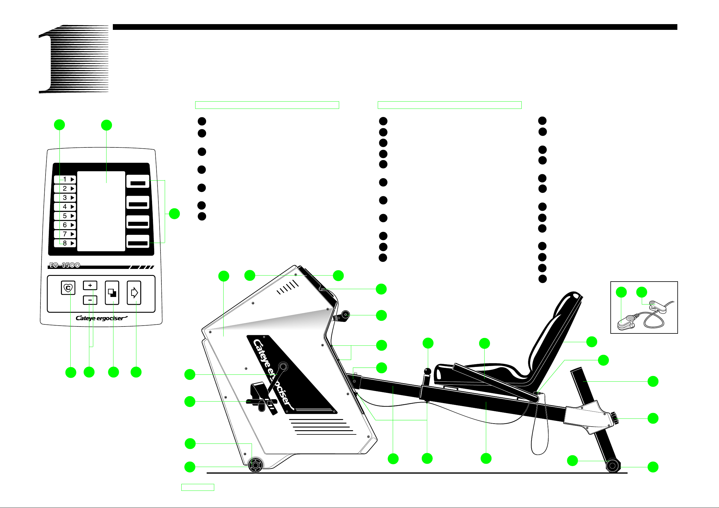
ANATOMY OF THE EC-3500
G
LOADING
LEVEL
A
MODE
PULSE
PULSE
CADENCE
SPEED
TIME
DISTANCE
WORK RATE
CALORIE
B
Control Panel
A Display screen
B Mode
(Indicates what each figure stands for.)
C Advance Button
(Makes the program proceed to the subsequent stage.)
D Mode Button
(Selects data to input or display.)
E Set Button
(Modifies figures to input.)
F Target Pulse On/Off Button
G Loading Level
(Indicates grade of work load.)
1
2
Main Body
1 Main Unit
2 Control Panel Cover
3 Control Panel
4 Pulse Sensor Jack
5 Workload Shift Lever
(Changes workload level.)
6 Cable Hooks
(Holds pulse sensor cable.)
7 Joint
(Connects main body with rear frame.)
8 Seat Lock Pin
(Pull when adjusting seat position.)
9 Handlebar
10 Seat
11 Sensor Clip
(Holds sensor when not in use.)
3
12 Rear Support Pipe
13 Seat Height Lock Knob
(Loosen when adjusting seat height.)
14 Rear Leg
15 Level Adjuster
(For better stability of the unit.)
16 Seat Pipe
17 Cable Holder
(Holds pulse sensor cable.)
18 Inner Pipe
19 Front Leg
20 Caster
(For easy transportation of the unit.)
21 Pedal
22 Crank
23 Pulse Sensor
24 Cable Clip
TARGET
PULSE
ON/OFF
F
E
ADVANCEMODESET
D C
22
21
20
19
EC-35OO
4
23 24
5
6
8
9
10
11
7
12
13
18
17 16
15
14
2
Page 3

CONTENTS
INTRODUCTION
FOR SAFE OPERATION
Introduction
Anatomy of the EC-3500
Let's assemble
Control unit adjustment
Let's have a ride
Let's learn operation of buttons & workload shift lever
Let's input your data
Let's start to exercise
3
2
4
6
8
10
12
14
Introduction
Thank you very much for your purchase of Cateye Ergociser Model EC-3500. The model EC-3500 is a recumbent type exerciser with a built-in computer designed to
allow aerobic exercise conveniently for the purpose of advancing your cardiovascular system, and maintaining and
improving physical endurance.
You can do aerobic exercise effectively when your pulse
rate meets constantly a target pulse rate that is decided under your age, physical strength and purpose.
Reclining posture can be changed by adjusting the height
of seat. Have a ride in an appropriate posture according to
your purpose that may vary from rehabilitation to intense
training.
Read this manual carefully to achieve maximum fitness
from your EC-3500 and keep it handy.
For Safe Operation
For your safety, always observe the following.
1. Before using the EC-3500, it is important to consult a
medical specialist if you are suffering from any of the
following: heart disease (angina pectoris, myocardial infraction), hypertension, diabetes, respiratory disease
(asthma, chronic bronchitis, pulmonary emphysema,
etc.), articular metamorphosis, rheumatism, gout, or any
other diseases and physical complaints.
2. If you are not used to regular physical activities, it may
be dangerous to suddenly start strenuous exercise. Try to
increase your exercise level gradually and always avoid
careless exercise.
3. If you feel sick or sense something is wrong with your
body during exercise, immediately stop exercising.
4. If you are pregnant or physically weak due to any dis-
ease, you should always consult a medical specialist
prior to doing exercise with the EC-3500.
Make sure all components are included in the package.
If anything is missing, please contact your dealer.
Package 1
1. Main Unit
2. Seat Pipe, Inner Pipe
3. Rear Support Pipe
4. Front and Rear Legs
5. Pedals (L,R)
6. Handlebar
7. Pulse Sensor
8. Sensor Clip
9. Cable holders
10. Mounting screws (4 large, 4 small)
11. Batteries (AAx4)
12. Spanner Wrench, Hexagon Wrenches (2)
13. Operating Instructions/Warranty Registration Card
Package 2
14. Seat
14
4
1
EC-35OO
2
3
5
6
Purpose of exercise/Exercise program/Fitness terms
Maintenance/Trouble shooting/Specifications
Limited warranty
2
16
18
20
Warning:
This equipment has been certified to comply with the
limits for a Class B computing device, pursuant to Subpart J of Part 15 of FCC Rules. Only peripherals (computer input/output devices, terminals, printers, etc.)
certified to comply with the Class B limits may be attached to this computer. Operation with non-certified
peripherals is likely to result in interference to radio
and TV reception.
7
11
8
9
12
R
R
E
C
U
M
B
E
N
Cateye ergociser
T
T
Y
P
E
M
O
D
O
E
P
L
E
E
R
C
A
-
T
3
I
5
N
O
G
O
IN
S
T
R
U
C
T
IO
N
S
10
RECUMBENT TYPE
EC-35OO
13
3
Page 4

LET'S ASSEMBLE
Assemble the main unit under the following process.
1. Mounting Front Leg
• Remove the leg plate from the main unit.
• Place the front leg (with casters) under the main unit as
shown in Fig. 1 and fasten screws securely with the hexagon wrench making sure nuts locate at the bottom of the
leg.
hexagon
wrench
Fig. 1
front leg
(with casters)
nuts
2. Mounting Rear Leg
Place the rear leg (with level adjuster) under the rear support pipe as shown in Fig. 2 and fasten screws securely
with the hexagon wrench making sure nuts locate at the
bottom of the leg.
Fig. 2
5. Connecting Inner Pipe
• Remove the 3 screws from the end of the inner pipe.
• Insert the inner pipe into the joint metal of the main unit
and fasten it securely with the 3 screws.
joint metal
screws
inner pipe
Fig. 5
7
8
6. Mounting Pedals
• Attach the pedals to cranks using the spanner wrench
#15.
• Be sure to install the pedal (R) on the right crank and (L)
on the left crank to avoid cross threading.
Fig. 6
(L)
spanner
wrench
#15
(R)
FRONT
7. Setting Distance Scale
• Remove the control panel cover by loosening the screws
as shown in Fig. 7.
• Remove the control unit and pull out the battery case as
4
shown in Fig. 8.
• Turn over the control unit and switch to "KM" or "MILE"
to set your desired distance scale.
Fig. 7
KM
5
MILE
KM
MILE
7
8
5
6
3
4
1
2
rear leg
(with level adjuster)
nuts
3. Mounting Seat and Handlebar
Mount the seat to the seat pipe using the large screws and
the handlebar using the small ones.
large screws
Fig. 3
spring washer
flat washer
small screws
spring washer
flat washer
handlebar
3
2
4. Assembling Rear Frame
• Loosen and remove the seat height lock knob.
• Insert the rear support pipe into the socket of seat pipe.
Select any height and tighten the knob.
seat height
lock knob
rear support pipe
Fig. 4
EC-35OO
control
panel cover
PUSH-OPEN
battery case
Fig. 8
8. Loading (Replacing) Battery
• Load batteries (AA sizex4) in the battery case, making
sure the polarity + or – is right as shown in Fig. 9. Insert
the case into the control unit.
• Replace the control unit in position. Fit the panel cover
6
1
and tighten the screw. (Fig. 7)
•
Press the set buttons and the mode button ( )
simultaneously, and keeping these buttons held down
press the advance button to clear all readings. (Fig. 10)
• All LCD segments appear for about 2 seconds and then
disappear. (refer to "Special functions of buttons" in page
10.)
TARGET
PULSE
Fig. 9
ON/OFF
R6 : AA
R6 : AA
Fig. 10
ADVANCEMODESET
4
5
Page 5

ADJUSTMENT
Make each adjustment under the following process.
5
2
EC-35OO
Ideal exercise posture
• Adjust the seat position as illustrated. Find the position
where your knee is slightly bent when the pedal is at the
farthest position.
3
cable holders
4
1. Level Adjustment
• Turn the level adjuster on the rear leg so that the unit is
placed stably.
• When the indication line on the level adjuster is at the
top, the rear leg is at the same level as the caster of the
front leg.
7
8
5
Fig. 1
6
3
4
1
2
level adjuster
indication line
1
2. Adjusting Seat Position
The seat position can be adjusted while pulling up the seat
lock pin. When desired seat position is obtained, release
the lock pin free and move the seat slightly and the lock pin
will click into the nearest hole by spring pressure. Holes
are provided at an interval of 3 cm(1-3/16").
Note: When sliding the seat, take care not to break the
pulse sensor cable.
PULL
lock pin
3 cm(1-3/16")
Fig. 2
seat height
lock knob
3. Adjusting Seat Height
• The seat height can be adjusted at your choice.
• The higher the seat, the less intense the exercise or vice
versa.
• Loosen and remove the seat height lock knob, supporting
the seat pipe with the other hand.
• Move up or down the seat pipe to the desired height and
screw-in the seat height lock knob. While tightening the
knob lift the seat pipe slightly for easier screwing. Holes
are provided at an interval of 3 cm(1-3/16").
seat height
lock knob
Fig. 3
EC-35OO
• When moving the
main unit, lift the rear
frame holding by the
seat height lock knob,
and roll the casters.
casters
5. Mounting Pulse Sensor
• Insert the pulse sensor plug into the pulse sensor jack at
the side of the control panel.
• Attach the cable holders at the main frame and the seat
pipe. (Upper figure on page 6)
• Insert the sensor cable through the cable hooks and cable
holders. Hold the cable in position by attaching the sensor clip at the bend of the handlebar. (Fig. 4)
• Allow enough slack in cable under the seat pipe for seat
adjustment.
• Attach the cable clip to your clothes during exercise to
avoid excessive swinging of the sensor cable.
• Attach the pulse sensor on the sensor clip when not in
use.
pulse sensor jack
pulse sensor plug
pulse sensor
Fig. 4
4. Adjusting Pedal Belts
It is possible to adjust the pedal belt length according to
your shoes size.
6
cable holders
7
cable hooks
sensor clip
cable clip
Page 6

E
E
C
A
D
E
C
Attach Pulse Sensor
LET'S HAVE A RIDE
Try a ride so that you can familiarize yourself with the unit.
Press Adv Button
Make sure Initial Display
appears
Press Adv Button
Begin Exercise
Press Md Button
Make sure In-Exercise
Display(A) and (B) appear
Operate Workload Shift
Lever/ Make sure Pedal
Resistance changes
Finish Exercise when Buzzer
beeps to signal the end.
Press Adv Button
LOADING
LEVEL
TARGET
PULSE
ON/OFF
MODE
PULSE
PULSE
CADENCE
SPEED
TIME
DISTANCE
WORK RATE
CALORIE
ADVANCEMODESET
LOADING
LEVEL
TARGET
PULSE
ON/OFF
No-Display Screen Initial Display Screen
When power is off, no display appears on the screen. In this state, the
battery consumes minimal power.
When the unit is not in use, turn off
to "No-Display" state.
• If input signal is not entered into
the control unit in 10 minutes, the
unit is automatically turned off to
"No-Display" state.
In the "No-Display" state, this "Initial Display" appears with a press of
the Advance button .
• Preset Initial Display (from top)
• Upper-Limit Pulse Rate
160 bpm (beats per minute)
• Target Pulse Rate
120 bpm (beats per minute)
• Target Exercise Time
15 minutes
• Age
40 years old
Before starting exercise, input your
age, target exercise time and target
pulse rate, in accordance with your
purpose.
PLL
AGE
TPL
min
sec
MODE
PULSE
PULSE
CADENCE
SPEED
TIME
DISTANCE
WORK RATE
CALORIE
ADVANCEMODESET
LOADING
LEVEL
TARGET
PULSE
ON/OFF
rpm
min
sec
watt
MODE
PULSE
PULSE
CADENCE
SPEED
TIME
DISTANCE
WORK RATE
CALORIE
ADVANCEMODESET
In-Exercise Display (A)
Screen
After the "Initial Display" state, this
"In-Exercise Display (A)" appears
with a press of the advance button .
• Exercise Display (A) Screen
(from top)
• Current Pulse Rate
(bpm)
• Pedal Cadence
(rpm-revolutions per minute)
• Countdown Timer
(minute:second)
• Work Rate
(watt)
If you press the advance button av
when the screen is in this state, it turns
to the "No-Display" state.
LOADING
LEVEL
TARGET
PULSE
ON/OFF
mile/h
mile
kcal
MODE
PULSE
PULSE
CADENCE
SPEED
TIME
DISTANCE
WORK RATE
CALORIE
ADVANCEMODESET
In-Exercise Display (B)
Screen
The In-Exercise Display (A) and (B)
are alternative. With a press of the
mode button , they alternate.
• In-Exercise Display (B) Screen
(from top)
• Current pulse Rate
(bpm)
• Simulated Current Speed
(mile/h or km/h)
• Simulated Trip Distance
(mile or km)
• Calorie Consumption
(kcal)
If you press the Advance button av
when the screen is in this state, it turns
to the "No-Display" state.
LOADING
LEVEL
TARGET
PULSE
ON/OFF
No-Display Screen
MOD
PULS
PULS
CADEN
SPEE
DISTAN
WORK R
CALORI
ADVANCEMODESET
TIME
8
9
Page 7

LET'S LEARN OPERATION OF BUTTONS &
WORKLOAD SHIFT LEVER
To make the most of the functions of the unit.
1. Functions of the buttons
• Advance Button ( AV )
It makes the program proceed. Each time you press this button, the display
advances in the order as Fig. 1.
• Mode Button ( MD )
It is used in two ways.
a) In the "Initial Display", each press of this button advances the mode
and the figure to be modified blinks in the order as Fig. 2.
b) In the "In-Exercise Display", each press of this button converts the
screen alternately as Fig. 3.
• Set Buttons (SET)
In the "Initial Display", each button serves to change the blinking numerical value in each selected mode.
+ Button.... Each press increases the numerical value by 1, and when
held down, it increases rapidly.
– Button.... Each press decreases the numerical value by 1, and when
held down it decreases rapidly.
• Target Pulse On/Off Button ( TP )
Each time you press this button, the () mark is switched on or off. When
the mark is lit up on the screen, the buzzer warns you if your pulse rate is
out of the target pulse rate by more than ±5 bpm . When the mark is not lit
up on the screen, the buzzer doesn't function and you can exercise freely
unconcerned with the target pulse rate zone.
[Beeping Sound Pattern] 0 1 2 (sec)
Over (the target pulse rate +5) 2kHz
Under (the target pulse rate –5) 1kHz
(The buzzer doesn't function unless your pulse rate once reaches the target
pulse rate.)
Special functions of buttons
• "All Clear" Function
When new batteries are loaded, or when abnormal signal is received due to
electrostatic trouble, etc., the screen may show abnormal displays. In such
a case, first hold down the set buttons +- and the mode button M
simultaneously, then press the advance button A . The screen first turns to
"No-Display" state, then it displays all the readings for 2 seconds. Finally
it returns to the "No-Display" state.
• Recovery Function
If you press the advance button A by mistake during exercise, making the
screen turn to "No-Display" state, press any of the other buttons, except the
advance button A , within 10 seconds. The screen recalls the previous
"In-Exercise Display" state.
• Memory Function
In the "No-Display", if you hold down the mode button M and press the
advance button A , the data that was set for your last exercise can be
recalled. This function is useful when you can use the unit exclusively and
want to repeat the same exercise program.
*This function becomes effective 10 seconds after the unit is turned off.
•Advance Button ( AD )
NO-DISPLAY
INITIAL DISPLAY
IN-EXERCISE DISPLAY A/B
Fig. 1
•Mode Button ( MD )
AGE
TARGET EXERCISE TIME
TARGET PULSE RATE
UPPER-LIMIT PULSE RATE
Fig. 2
IN-EXERCISE DISPLAY (A)
IN-EXERCISE DISPLAY (B)
Fig. 3
Screen Display
mile/h
km/h
watt
kcal
PLL
TPL
rpm
min
sec
mile
km
AGE
1
2
3
4
5
6
Fig. 4
• Before starting exercise, set the workload shift
lever to the following standard level in accordance with your age and sex.
Age Male Female
20~30's 3 2
40~50's 2 1
Over 60 1 1
7
8
Work rate (watt) is determined by the position of the workload shift
lever, and your pedal cadence. (Fig. 4). To get the desired work rate
during exercise, first adjust it roughly by the workload shift lever,
then precisely by changing your pedal cadence. The workload can be
shifted to 8 positions, 1 is the easiest and 8 is the heaviest. Each position of the workload shift lever is identified by the mark displayed
on the screen. The following table shows work rate (watt) corresponding to each workload shift lever position, and the pedal cadence.
Work Rate (watt)
Pedal Cadence 50 60 70 80 100 120
Shifting Position
1 253341506585
2 50 65 85 105 140 195
3 75 100 130 155 215 265
4 100 135 170 210 285 355
5 125 165 215 260 350 440
6 150 200 255 310 420 520
7 175 235 295 355 480 595
8 200 265 335 405 545 680
3. Pulse Sensor Handling
• Attach the pulse sensor to either earlobe, right or left. Clip it firmly
to the center of the earlobe. Be sure to remove any earring or the like
from your earlobe. (Fig. 5)
2. Workload Shift Lever and Work Rate
Fig. 5
1 Workload Shift Position Mark
1
2
3
4
5
6
4
7
4
7
8
Indicates the position of the workload shift lever
2 Pulse Sensor "OK" Mark
Indicates that the pulse sensor functions properly.
3 "Error" Mark
Appears when the pulse rate jumps up or down
abnormally, or when the pulse sensor is not attached to
your earlobe properly.
4 Mode Mark
Indicates the mode in display.
PLL--- Upper-Limit Pulse Rate
TPL--- Target Pulse Rate
AGE -- Age of the user
5 Pulse Mark
Flickers synchronized with the pulse
6 Target Pulse Rate On/Off Mark
When this mark is on, the buzzer functions to signal
when your pulse rate is out of the target pulse rate zone.
7 Unit Mark
Indicates the unit of the display figure.
8 Battery Alarm Mark
Indicates that the battery power has exhausted.
• When it is cold, rub your earlobe before attaching the pulse sensor,
to facilitate the blood circulation.
• Try not to change the position of the earlobe sensor during exercise.
• If the error mark lights up frequently, remove the pulse sensor
and attach it again correctly.
• If the pulse sensor is pulled excessively, the cable can be damaged or
short-circuited. Treat the pulse sensor with care.
• When the pulse sensor is not in use, always clip it to the sensor clip.
Hold the pulse sensor cable with the cable clip, adjusting the slack of
the pulse sensor cable.
Checking the pulse sensor
1) In the "In-Exercise" state, close the pulse sensor; putting nothing in
between.
The mark lights up on the screen, and the pulse rate readings
show "0" bpm ----- Normal
When the pulse sensor cable is pulled, the mark blinks ----- The
sensor cable is about to be broken.
The mark doesn't light up ----- The pulse sensor cable is
broken.
2) The mark blinks even when the pulse sensor is attached to your
earlobe. ----- The pulse sensor cable is short-circuited.
10
11
Page 8

LET'S INPUT YOUR DATA
The target pulse rate calculated from your age is the key of
effective exercise.
Adjusting Seat Position
Adjusting Seat Height
Attaching Pulse Sensor
Press Advance button
Input your data
Adjust the seat position to get correct exercise posture.
Choose the seat height to your preference.
Attach the pulse sensor to your earlobe firmly.
Press the advance button to turn on the Initial Display.
Input your age and target exercise time, and if necessary modify the target pulse rate.
LOADING
LEVEL
LOADING
LEVEL
PLL
TPL
AGE
PLL
TPL
AGE
min
sec
min
sec
MODE
PULSE
PULSE
CADENCE
SPEED
TIME
DISTANCE
WORK RATE
CALORIE
MODE
PULSE
PULSE
CADENCE
SPEED
TIME
DISTANCE
WORK RATE
CALORIE
1. Press Advance Button A
1) Set the seat at the position where you can take the correct exercise posture,
then adjust the seat height at your choice (Page 7).
1) Press the Advance button A and make sure that the "Initial Display" is
shown on the screen. If you want to modify the "Age" and/or the "Exercise
Time", proceed to 2 and 3 in order. If no modification is needed, proceed to 5.
2) If you want to modify the "Target Pulse Rate" from the automatically preset
value, proceed to 3, then to 4.
2. Input Your Age
1) Press the mode button M , and the numerical value "40" at the bottom flickers, which is the preset standard age.
2) Input your age, using the set button + or – .
* Each time the age is modified, the upper-limit pulse rate (PLL) and the target
pulse rate are automatically set, based on "200 - age" and "160 - age" respectively.
For a person who has built up enough physical strength:
The target pulse rate more than [your upper-limit pulse rate 10] cannot be input. If you wish to have a higher target pulse
rate, modify the upper-limit pulse rate upward, then input the
desired target pulse rate. The target pulse rate can be input up
to 189 bpm.
• How to modify the upper-limit pulse rate
1) Press the mode button until the upper-limit pulse rate
(value in the top line) flickers.
2) Input the desired upper-limit pulse rate using the set button
+ or – .
• In general, modification of the upper-limit pulse rate is not
always recommended because the target pulse rate that is
based on [180 - age] would be adequate for effective exercise.
LOADING
LEVEL
LOADING
LEVEL
PLL
AGE
PLL
AGE
TPL
min
sec
TPL
min
sec
MODE
PULSE
PULSE
CADENCE
SPEED
TIME
DISTANCE
WORK RATE
CALORIE
MODE
PULSE
PULSE
CADENCE
SPEED
TIME
DISTANCE
WORK RATE
CALORIE
3. Input Target Exercise Time
1) Press the mode button M , to make the numerical value "15:00" in the third
line flicker, which is the preset standard exercise time.
2) Input the desired exercise time, using the set button + or – .
4. Input Target Pulse Rate
1) Press the mode button M to make the numerical value "120" in the second
line flicker, which is the preset standard target pulse rate.
2) Input the desired target pulse rate, using the set button + or - .
12
13
Page 9

LET'S START THE EXERCISE
Continuing exercise with the EC-3500 will make you fit.
Adjust Workload Level
Press Advance Button
(Start of Exercise)
Press Mode Button, and make
sure In-Exercise Display (A)
and (B) appear alternately.
Finish Exercise when Buzzer
beeps to signal the end.
Check your data
Set the workload shift lever at an appropriate position, in accordance with your age and sex.
Upon pressing the advance button , start pedaling.
You can read various data by pressing the mode button .
When you have reached the target exercise time, the buzzer signals the end. (After the timer has reached the target exercise
time, it starts to count-up.)
Press the mode button to check the data, and record them.
Press the advance button to turn off the screen to No-Display
state.
LOADING
LEVEL
LOADING
LEVEL
LOADING
LEVEL
PLL
TPL
min
sec
AGE
rpm
min
sec
watt
mile/h
MODE
PULSE
PULSE
CADENCE
SPEED
TIME
DISTANCE
WORK RATE
CALORIE
MODE
PULSE
PULSE
CADENCE
SPEED
TIME
DISTANCE
WORK RATE
CALORIE
MODE
PULSE
PULSE
CADENCE
SPEED
5. Adjust Workload Level
Set the workload shift lever at the following suggested position, in accordance
with your age and sex.
Age Male Female
20~30's 3 2
40~50's 2 1
Over 60 1 1
6. Start Exercising
1) After setting the data, press the advance button A and start pedaling. The
timer starts to countdown, so the remaining time is shown.
2) Keep pedaling in the range of 50~70 rpm, increasing the workload level by
one point per minute, so that your pulse rate comes close to the target pulse
rate smoothly.
3) After your pulse rate once reaches the target pulse rate, the buzzer will beep if
your pulse rate is out of the target pulse rate zone (the target pulse rate ±5). In
such a case, adjust your pedal cadence upward or downward by 5 rpm so that
your pulse rate can stay within the target pulse rate zone.
* In case you cannot get back to the target pulse rate zone by only changing the
pedal cadence, adjust the workload shift lever to change the workload level
upward or downward by one point.
7. Alternate Display
With a press of the mode button M , the In-Exercise Display (A) and the InExercise Display (B) can alternate each other during exercise. You can watch
different data while you exercise.
WARNING
If the buzzer beeps to signal that your pulse rate has exceeded the upper-limit
pulse rate, stop exercising immediately.
Beeping sound pattern 0 1 2(sec.)
When the upper-limit pulse rate
has been overpassed
Target pulse rate
When the target exercise time has elapsed
Over (+) 5 bpm
Under (-) 5 bpm
14
LOADING
LEVEL
mile
kcal
mile/h
mile
kcal
TIME
DISTANCE
WORK RATE
CALORIE
MODE
PULSE
PULSE
CADENCE
SPEED
TIME
DISTANCE
WORK RATE
CALORIE
8. Finish Exercise
1) When the buzzer beeps to signal the end of the target exercise time, finish
exercise. Recall the In-Exercise Display (B) screen, by pressing the mode
button M .
2) Check the consumed calories (kcal) and the simulated trip distance (mile or
km). Press the advance button A to turn off the screen to the "No-Display"
state.
* You may continue exercise even after the buzzer beeps to signal the end, if
you have not reached to your target of consumed calories. After counting
down to the preset target exercise time, the timer starts counting up.
15
Page 10

PURPOSE OF EXERCISE/EXERCISE PROGRAM/FITNESS TERMS
To maximize the benefit of your exercise.
1. Purpose of Exercise
Do you often get out of your breath when you go up stairs
or walk fast? This is because your ability to take oxygen
into your body is getting weak. Such ability is evaluated
by a value called MOU (Maximum Oxygen Uptake),
which represents the maximum amount of oxygen taken
into your body per 1 kg of body-weight in a minute (ml/
kg.min.). The MOU value can be used as a scale of your
physical endurance.
The average MOU value is 40-50 ml/kg.min. for men in
their twenties, and 30-40 ml/kg.min. for women of the
same age. In general, the MOU value becomes less as you
get older, and the more you lack proper exercise, the faster
it decreases. It is said the MOU value less than 22 ml/
kg.min. may result in illness of cardiovascular system,
and in restriction of your daily life.
Continued aerobic exercise several times per week maintains and improves your MOU value, activating oxygen
supply to your cardiovascular system. With the EC-3500,
you can perform aerobic exercise effectively and efficiently.
2. Exercise Program
Aerobic exercise will be more effective when it is continued at a certain pulse rate, which is determined based on
your age and physical strength. This is called "Target
Pulse Rate".
•How to decide your target pulse rate
When you input your age, the EC-3500 automatically sets
your target pulse rate at [160 - age]. This target pulse rate
corresponds to 50-60 % of the exercise level for the twenties, 40-50 % for the sixties. (Refer to "Exercise Level" on
page 17.) The older you are, at the less intense level your
target pulse rate is set because of such programming of the
EC-3500. The exercise level automatically set by this unit
could be too hard even for a young person, if he is a beginner. If you feel it too hard, you may decrease the target
pulse rate by 10 bpm from the original level. If you feel
too easy, you may increase it by 10 bpm so that you can
continue exercise in the appropriate target zone as illustrated. If you can continue your exercise at the target pulse
rate of [180 - age], your exercise can be considered as effective enough. Upgrade your exercise gradually so that
you can reach the suggested final target of [190 - age].
PULSE RATE (bpm)
200
MAXIMUM PULSE RATE (220-AGE)
180
MAXIMUM PULSE RATE x 85%
160
MAXIMUM PULSE RATE x 70%
140
TARGET PULSE RATE CHART
UPPER-LIMIT PULSE RATE (200-AGE)
TARGET ZONE
190-AGE
MAXIMUM PULSE RATE x 60%
120
100
20 30 40 50 60 70
TARGET PULSE RATE AUTOMATICALLY SET (160-AGE)
180-AGE
(AGE)
•Exercise Time for Each Session
A minimum of 30 minutes exercise is necessary for each
session of exercise. A 5 minute warm up period, and 20
minutes of exercise time, with a 5 minute cool down period, is suggested as a standard exercise. For weight reducing exercise, over 30 minutes exercise time at the low
level of the target pulse rate is recommended with a 5
minute cool down.
•How many days a week for exercise
Minimum two exercise days a week is required just to
maintain your present fitness level. With 3-4 exercise
days you can expect improvement. Always consult with
your doctor before proceeding with any exercise program.
*Caution:
Concentrated and repeated exercise in a day may produce
an adverse result.
3. Fitness Terms
• Maximum Heart Rate
When you exercise, your heart rate continues to increase
as the exercise level becomes more intense, but there is a
certain limit. This limit is called the maximum heart rate.
The maximum heart rate decreases as you become older.
The decrement ratio in the maximum heart rate differs individually, depending on whether one is physically well
trained or not. In general, the maximum heart rate decreases yearly by 0.6-1.0 beats per minute.
The heart rate is the number of heart beats per minute measured by a cardiometer. However, we can measure the
pulse by touching the arteries near the skin, such as carotid
arteries; which is called the pulse rate.
At the earlobe, blood flow fluctuates with each beat of the
heart, and the optical permeability through the earlobe
changes every time the heart beats. The EC-3500 measures the pulse rate with the sensor, amplifying the changes
of optical permeability. An earlobe is a suitable part for
sensing the pulse rate during the physical exercise since its
muscular movement during exercise is very little and
doesn't affect the pulse rate detection.
The heart rate and the pulse rate differ from each other in
principle and method, but their value per minute is equal,
and therefore both can be interpreted as synonymous.
• Upper-Limit Pulse Rate (PLL)
The maximum pulse rate is related with the age, and is
calculated by standard formulas such as [220 - age] or
[204 - 0.69 x age]. In the EC-3500, it is calculated as [200
- age] and called the upper-limit pulse rate (PLL), which is
lower than the standard formula of the maximum pulse
rate and gives you a safer upper-limit pulse rate. When
your pulse rate exceeds the preset upper-limit pulse rate, a
buzzer beeps to warn you. You can adjust the upper-limit
pulse rate according to your physical condition.
• Target Pulse Rate (TPL)
A pulse rate to be maintained during the exercise is called
the target pulse rate (TPL). When your pulse rate is more
than 5 bpm over or under the target pulse rate which you
set before the exercise, a buzzer beeps to signal you.
• Exercise Level
Since the pulse rate gets higher according to the intensity
of exercise, the exercise level can be indicated by how
high your pulse rate is compared with your pulse rate at
rest. It is shown by percentage as follows:
Exercise Level (%) =
Therefore, the target pulse rate for a certain exercise level
can be obtained through the following formula:
Target Pulse rate = (Maximum Heart Rate - Pulse Rate at rest)
Pulse Rate in exercise - Pulse Rate at rest
Maximum Heart Rate - Pulse Rate at rest
x 100
Exercise Level (%)
x +
100
Pulse Rate at rest
16
17
Page 11

MAINTENANCE/TROUBLE
SHOOTING/SPECIFICATIONS
1. Caution on Handling
For longer use, observe the following precautions.
• Don't disassemble the main unit or the control unit. Consult the dealer you
purchased the unit from, in case of trouble.
• Avoid using this unit where it may be splashed with water or there is a high
temperature or humidity.
• When the unit is not in use, be sure to turn the power off.
• Don't wipe the unit with organic solvents such as thinner, kerosene, gasoline
or alcohol. Wipe it clean with a cloth with neutral cleanser, and wipe with a
dry cloth.
• Wipe off the sweat drops on the main unit and control unit, after use.
• Don't leave the unit in the direct sun light.
2. T r ouble Shooting
Trouble Check Item Suggested Remedy
No display appears or
abnormal display
appears on the control
panel.
A buzzer beeps
continuously.
"Distance Scale Unit"
display is wrong.
The pulse rate reading
is not displayed.
The target pulse rate
alarm does not beep.
Press the advance button A
and check if the display appears
or not. Proceed "All-clear
Process", and press the advance
button A and check if the
display appears or not. [Page 5-8
(Fig. 10)]
Check if your upper-limit pulse
rate (PLL) has been set correctly.
[Page 13-2]
Check if the distance scale unit
was set correctly according to
instructions. [Page 5-7]
Check if the sensor plug is
inserted properly. [Page 7-5]
Check if the pulse sensor is
correctly attached to your
earlobe. [Page 11]
Check if the plug or the cable of
the pulse sensor is damaged.
[Page 11]
Has your pulse rate once reached
the target pulse rate? [Page 10]
Is the Target Pulse On/Off mark
. lit on the screen? [Page 10]
If still no display
appears, the batteries
are dead. Replace all
four batteries. [Page 58 ]
Input your age
correctly. The upperlimit pulse rate is set
based on [200 - age].
Follow instructions on
page 5-7,8 to set the
desired distance unit.
Insert the sensor plug
properly, and attach the
pulse sensor correctly.
In case of damage on
the pulse sensor,
replace it with a new
one.
The target pulse rate
alarm is activated only
after your pulse rate
reaches the target.
Press the Target Pulse
On/Off button to
turn on the C mark.
ITEM SPECIFICATIONS
Load Eddy current system utilizing permanent magnet
Load Range Manual Adjustment 1~8 level
Cadence 50~120 rpm
Load Range 25~680 watts
Acceleration 2-step chain drive incorporating timing belt
Control System 4-bit micro-computer
Display Function Function Range Accuracy
Pulse Rate 50 ~ 220 bpm ± 1 bpm (stable state)
Cadence 20 ~ 240 rpm ± 1 rpm
Exercise Time 00 min. 00 sec. ~ 99 min. 59 sec. ± 0.003 %
Work Rate 0 ~ 999 watts ± 5 watts (at 50 watts)
Speed 0 ~ 99 miles/h (km/h) Simulated value
Distance 0.00 ~ 99.99 miles (km) Simulated value
Calorie 0 ~ 999 kcal Estimated value
Alarm Function Target Pulse Rate Alarm
Signals if the pulse rate deviates by ±5 bpm from target pulse rate
Upper-limit Pulse Rate Alarm
Signals when pulse rate exceeds preset upper-limit pulse rate
Exercise Time Alarm
Signals when preset target exercise time is reached
Power Supply AA (R6) x 4 (Battery life: Approx. 200 hours by alkaline battery)
User's Weight Limit 286 lbs (130 kg)
Measurement Overall Length: 75-3/16 inches max. (1910 mm)
Unit Hight: 14-31/32 inches max. (847 mm)
Width: 22-1/16 inches (560 mm)
Seat to Crank Axle Distance: 14-31/32 ~ 26-25/32 inches (380 mm ~ 680 mm)
Seat Hight: 11-11/32 ~ 19-3/32 inches (288 mm ~ 485 mm)
Crank Axle: 17-1/8 inches max. (435 mm) from floor
Weight Net Weight: 73 lbs. approx. (33 kgs)
*Specifications and design are subject to change without notice.
Pat. & Design Pat. Pending
Copyright© 1991
Cateye Co., Ltd.
Printed in Japan
ECME35-910925
18
19
Page 12

LIMITED WARRANTY
CAT EYE & IMPORTER LIMITED WARRANTY
Cat Eye Co., Ltd. and Importer warrant that the CATEYE ERGOCISER™
model EC-3500 is free from manufacturing defects in workmanship and materials and will repair or replace defective parts or equipment in the product for the
period of one (1) year from the date of purchase, excluding the batteries and the
pulse sensor, in accordance with conditions set forth below:
1. This warranty applies to the product only while the product (1) remains in the
possession of the original purchaser and (2) has not been subject to accident,
misuse, abuse, improper service, or non-Cat Eye modification.
2. This warranty does not cover damage or equipment failure caused by wiring
not in compliance with electrical codes, failure to provide reasonable and necessary maintenance, damage caused by an improper battery, or incorrect battery installation.
3. THIS LIMITED WARRANTY IS IN LIEU OF ALL OTHER WARRANTIES, EXPRESS OR IMPLIED (INCLUDING MERCHANTABILITY AND
FITNESS), AND OF ALL OTHER OBLIGATIONS OR LIABILITIES ON
THE PART OF CAT EYE & IMPORTER. We neither assume nor authorize
any person to assume for us any other obligation or liability in connection with
the sale of this product. Under no circumstances shall Cat Eye or Importer be
liable by virtue of this warranty or otherwise for damage to any person or
property whatsoever for any special, indirect, secondary, or consequential
damage of any nature however arising out of the use of, or inability to use, this
product.
[TO: U. S. CUSTOMER]
This warranty gives you specific legal rights, and you may also have other rights
which vary from state to state.
1) Some states do not allow the exclusion or limitation of incidental or conse-
quential damages, so the above limitation or exclusion may not apply to you.
2) Some states do not allow limitations on how long an implied warranty lasts, so
the above limitation may not apply to you.
4. Service under this warranty may be obtained by (1) obtaining a RETURN AUTHORIZATION FORM from your local dealer, (2) completing a RETURN
AUTHORIZATION FORM, and (3) shipping the defective part(s) or equipment, accompanied by the RETURN AUTHORIZATION FORM and the
original copy of purchase receipt, prepaid to Importer.
5. For your protection, please complete the CATEYE ERGOCISER Warranty
Registration and mail it to Importer at the time of purchase.
PROCEDURES FOR RETURN
Contact your local dealer for a RETURN AUTHORIZATION FORM. Part(s) or
equipment will not be accepted by Importer without the completed RETURN
AUTHORIZATION FORM and prepayment of any shipping charge.
20
Page 13

0689970
R
CO
.,LTD.
2-8-25 Kuwazu, Higashi Sumiyoshi-ku, Osaka 546 JAPAN
PHONE: (06)719-7781
FAX: (06)719-2362
 Loading...