

Page 1

OPERATOR’S MANUAL
Knuckleboom Loader
2410 - 2410 PH
Part No. 30015166
March 2012
Rev. A
Page 2

Page 3

TO THE OPERATOR
2410 i 1111
Page 4

TO THE OPERATOR
2410 ii 1111
Page 5
TO THE OPERATOR
TO THE OPERATOR
INTRODUCTION
DO NOT USE THIS MACHINE UNLESS YOU HAVE READ AND UNDERSTOOD THIS
MANUAL AND HAVE THE NECESSARY TRAINING AND AUTHORIZATION TO OPERATE
AND MAINTAIN YOUR MACHINE PROPERLY.
REMEMBER THAT YOU ARE THE KEY TO SAFETY. GOOD SAFETY PRACTICES PROTECT
YOU AND THE PEOPLE AROUND YOU. MAKE THIS MANUAL A WORKING PART OF YOUR
SAFETY PROGRAM.
2410 Loader
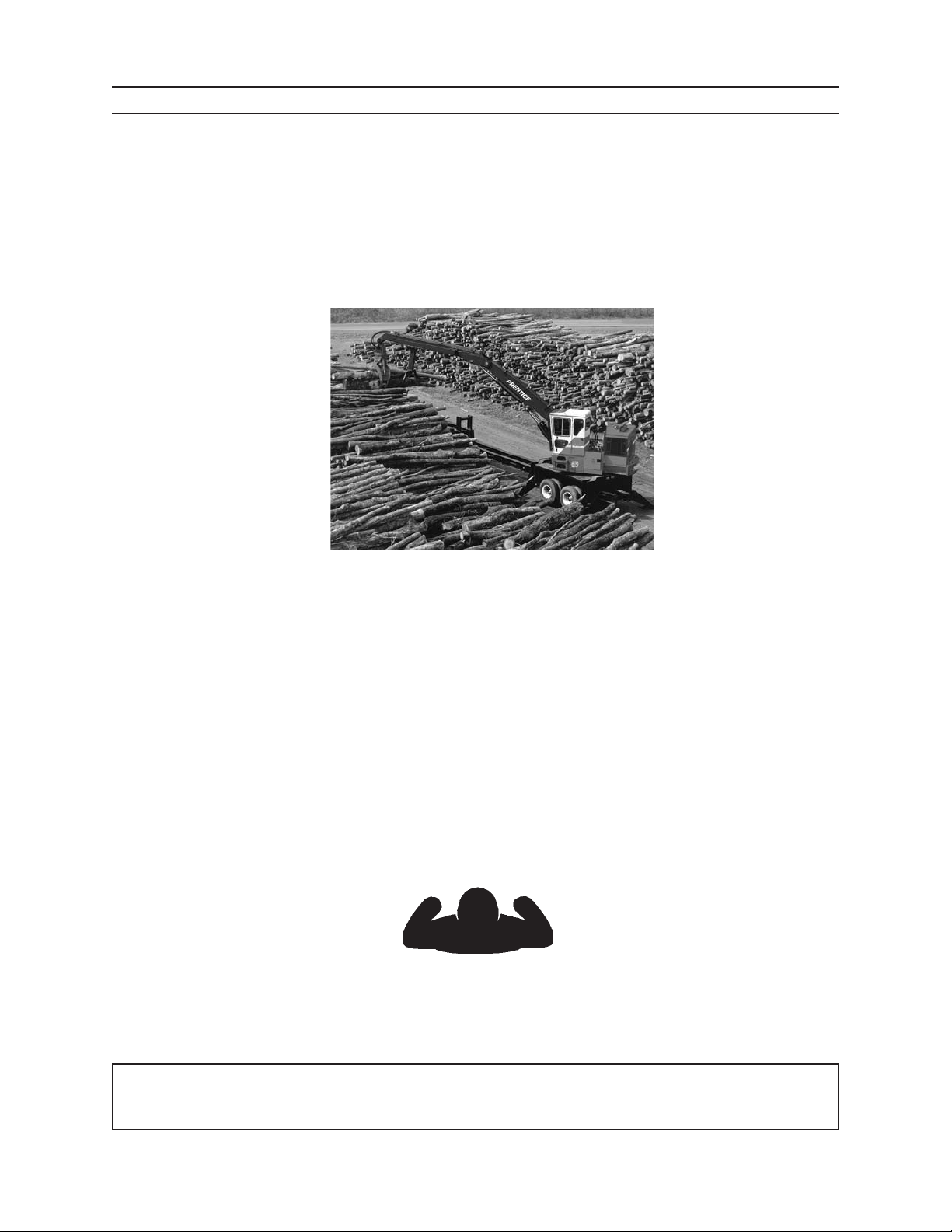
This operator's manual describes how to safely operate the Prentice Loaders. The Prentice loader is a truck
trailer–mounted loader used for handling random–length logs and tree–length stems.
Minimum trailer is a 40-foot (12.2 m) tandem-axle trailer (45-foot (13.7 m) for delimbers) with 40,000 pounds
(18,144 kg) GVW (gross vehicle weight) rating, and a mounting surface height of about 39 inches (99 cm).
Minimum truck is a 6 x 4 live tandem truck of not less than 50,000 pounds (22,680 kg) GVW rating. Truck must
have a double channel frame and minimum CA of 132 inches (334 cm). A CA of 144 to 168 inches (366 - 427 cm)
is recommended. A maximum CA for live heel of 144 inches (366 cm) is required.
CAPACITY AT MAXIMUM REACH: PER SAE J2417
2410 Knuckle Boom:
Follow the instructions in this operator's manual to safely operate the Prentice log loaders. Directions in this
manual are referenced from the operator's seat facing forward.
You can help improve this manual. If you nd any mistakes or if you know of a way to improve the procedures,
please let us know. Mail your letter to: ATTN: TECHNICAL PUBLICATIONS, Caterpillar Forest Products Inc.,
3249 S. COUNTY ROAD 45, P.O. BOX 568, OWATONNA MN 55060–0568.
32 foot (9.75 m) radius, 5 foot (1.5 m) elevation, 4,458 pounds (2,340 kg).
FORWARD
LEFT
BACK
RIGHT
This operator's manual includes information available and current at the time of approval for printing. Cater-
pillar Forest Products, Inc. reserves the right to improve its product without giving prior notice or incurring
obligation.
This operator’s manual should be regarded as part of the machine. Suppliers of both new and second
hand machines are advised to retain documentary evidence that this manual was provided with the machine.
2410 iii 1111
0209
Page 6
TO THE OPERATOR
DANGER
WARNING
NOTICE
CAUTION
SAFETY SYMBOLS
SAFETY ALERT SYMBOL
Means: ATTENTION. BE ALERT. YOUR SAFETY IS
INVOLVED.
This safety symbol is used for important safety messages.
When you see this symbol, follow the safety message to
avoid personal injury and/or property damage.
Understand signal words: DANGER, WARNING, and CAUTION are used with the SAFETY ALERT SYMBOL.
DANGER IDENTIFIES THE HAZARD OR
UNSAFE PRACTICE THAT WILL RESULT IN SEVERE
PERSONAL INJURY OR DEATH.
WARNING identies the hazard or unsafe practice
that could result in severe personal injury or death.
CAUTION identies the hazard or unsafe practice
that could result in personal injury or property damage.
NOTICE identies important installation, operation, or
maintenance information.
2410 iv 1111
0209
Page 7

TO THE OPERATOR
CONTENTS
PRODUCT PROTECTION PLAN
Machine i
Attachment .........................................................................ii
To the Operator ................................................................iii
Safety Symbols .................................................................iv
Contents ...............................................................................v
01 GENERAL SAFETY ........................................................11
Safety Alert Symbol .....................................................1-1
Operator Preparation ..................................................1-1
Avoid Contact with Stabilizers .................................1-1
Battery Safety .................................................................1-2
Control Shut O Lever ................................................1-2
Electric Lines ...................................................................1-3
Electric Storm .................................................................1-3
Falling or Swinging Logs ............................................1-4
Fire Prevention/First Aid .............................................1-4
Fluids Under Pressure..................................................1-5
Hand Holds & Steps .....................................................1-5
Hand Signals ...................................................................1-6
Hoses & Fittings .............................................................1-6
No Riders on Machine .................................................1-7
Operator Safety .............................................................1-7
Pinch Points ....................................................................1-7
Practice Safe Maintenance ........................................1-8
Pressure Settings ..........................................................1-8
Protective Clothing ......................................................1-9
Protective Devices/Equipment ................................1-9
Radiator Cap ...................................................................1-9
Refueling ....................................................................... 1-10
Starter Circuitry ..........................................................1-10
Unauthorized Welding ............................................. 1-10
Unstable Platform ...................................................... 1-11
02 SAFETY DECALS ...........................................................21
Loader ...........................................................................2-1
Carrier ...........................................................................2-2
Truck Mount Cab Interior ...........................................2-3
Bar Slasher/Delimber Cab Int. ..................................2-4
03 COMPONENT TERMINOLOGY .................................31
04 CONTROLS AND INSTRUMENTS ............................41
Operator’s Cab ..............................................................4-1
Instrument Console ...................................................4-2
Engine Coolant Temp. Wrng. Ind. ............................4-3
Low Coolant Warning Indicator ...............................4-3
Voltage Warning Indicator.........................................4-4
Hydraulic Oil Filter Warning Indicator ...................4-4
Fuel Gauge ......................................................................4-5
Engine Oil Pressure Warning Indicator .................4-5
Air Cleaner Warning Indicator ..................................4-6
Hydraulic Oil Temp Wrng. Indicator .......................4-6
Low Hydraulic Oil Wrng. Indicator ..........................4-6
Switch Panel ...................................................................4-7
Ignition Switch ...............................................................4-8
Dome Light .....................................................................4-8
Error Code Indicator Lights .......................................4-8
Circuit Breakers ..............................................................4-9
Heat Control Lever .......................................................4-9
Pilot Pressure Shut O ............................................. 4-10
Battery Disconnect Master Switch ...................... 4-10
Throttle ........................................................................ 4-11
Swing Pedal ................................................................. 4-11
Left Joystick .................................................................4-12
Right Joystick ..............................................................4-13
Right Joystick Rocker Switch ................................. 4-14
Stabilizer Controls .....................................................4-14
Hourmeter .................................................................... 4-14
Operator’s Seat ........................................................... 4-15
AM/FM Stereo Cassette ...........................................4-17
05 PRESTART INSPECTION ............................................51
Pre-Start Checks on the Ground .............................5-1
Pre-Start Checks on the Platform ............................5-2
Pre-Start Checks in the Cab ......................................5-3
Fire Prevention ...............................................................5-4
06 OPERATION.....................................................................61
General Guidelines .......................................................6-1
Electrocution Danger ..................................................6-2
Overhead Loads Warning ..........................................6-2
Getting on Machine .....................................................6-3
Machine Start Up ..........................................................6-3
Starting the Engine ......................................................6-4
Starting Machine with Booster Battery ................6-5
Indicator Lamp Checks ...............................................6-6
Cold Weather Starting
Engine Pump Disconnect ........................................6-8
Warm-up Period ............................................................6-9
Feathering the Controls .......................................... 6-10
Using Stabilizers ......................................................... 6-11
Landing Layout ........................................................... 6-12
Heeling - Picking up Logs .......................................6-12
Grapple Control .......................................................... 6-13
Stopping the Machine ............................................. 6-13
Getting o Machine .................................................. 6-14
2410 v 1111
Page 8

TO THE OPERATOR
CONTENTS
07 BREAKIN PERIOD ........................................................71
After First 10 Hours ......................................................7-1
After First 100 Hours ....................................................7-2
08 TRANSPORTING ............................................................81
09 FUELS AND LUBRICANTS ..........................................91
Fuel 9-1
Engine Oil .......................................................................9-2
Hydraulic Oil ...................................................................9-3
Grease ...........................................................................9-3
Grease for Swing Drive Bearing
and Swing Drive Motor ............................................9-4
Lubricant for Pinion and
Swing Gear Teeth .......................................................9-4
Lubricant for Swing Drive Gear Box .......................9-4
Cylinder Rod Corrosion Preventive ........................9-4
Engine Coolant Specications .................................9-4
Storing Lubricants ........................................................9-5
10 MAINTENANCE SAFETY .......................................... 101
Before Maintenance.................................................. 10-1
Practice Safe Maintenance .....................................10-1
Hydraulic Safety .........................................................10-2
Protective Clothing ...................................................10-2
Servicing Cotrol Valves, Cylinders, Pump s & ...........
Motors ................................................................... 10-3
Unauthorized Welding ............................................. 10-3
During Maintenance ................................................. 10-4
Battery Safety ..............................................................10-4
Cooling Fan .................................................................. 10-4
Diesel Exhaust ............................................................. 10-5
Fluids Under Pressure...............................................10-5
Fuels & Lubricants......................................................10-6
Pinch Points .................................................................10-6
Servicing Machine with Engine Running .......... 10-6
After Maintenance ..................................................... 10-7
Disposing of Waste .................................................... 10-7
Stroing of Flamable Materials ............................... 10-7
11 SCHEDULED/PERIODIC MAINTENANCE ..................
SERVICES ...............................................................................111
Lubrication and Maintenance Intervals ............. 11-1
Lubrication Notice ..................................................... 11-1
Position Machine for Maintenance ..................... 11-1
Maintenance Charts
As Required ............................................................. 11-2
Daily or Every 10 Hours .......................................11-3
Weekly or Every 50 Hours................................... 11-5
Monthly or Every 250 Hours .............................. 11-6
Every 500 Hours ..................................................... 11-7
Every 1000 Hours .................................................. 11-8
Maintenance Details
As Required ............................................................. 11-9
Check Electrical System ......................................11-9
Clean AC Condenser ..........................................11-10
Clean/Replace Recirculation Air Filter .........11-10
Fill Windsheild Washer Fluid Reservoir ........11-11
Clean Windsheild & Windows .........................11-11
Check/Replace Polycarbonate Window ................
Skylight ...............................................................11-12
Adjust Slasher/Delimber Saw Bar Chain ................
......................................................................11-12
Drain Replace Hydraulic Oil .............................11-13
Hazard Decals .......................................................11-13
Daily or Every 10 Hours .....................................11-14
Daily Visual Inspection ......................................11-14
Lube Adapter Knuckle .......................................11-14
Lube Stabilizer Pad & Pivot Points .................11-14
Lube Stabilizer Cylinder Road Ends ..............11-15
Lube Stablizer Arm Pivot Points .....................11-15
LubeStablizer Cylinder Base Ends .................11-15
LubeMain Boom Pivot Pins ..............................11-15
Lube Main Boom Cylinder Base Ends...........11-16
LubeMain Boom Cylinder Rod Ends .............11-16
Lube Main/Stick Pivot Pins ...............................11-16
Lube Stick Boom Cylinder Base Ends ...........11-16
Lube Stick Boom Cylinder Rod Ends ............11-17
Lube Swing Bearing ...........................................11-17
Lube Pinion Gear .................................................11-17
Check Hydraulic Oil Reservoir Level .............11-18
Fill Hydraulic Reservoir ......................................11-18
Prime the Pump ...................................................11-20
Air Cleaner Maintenance ..................................11-20
Unloader Valve .....................................................11-20
Inlet Hood ..............................................................11-20
Restriction Indicator ...........................................11-21
Cleaning Primary Element ...............................11-22
Check Fire Extinguisher ....................................11-23
Fill Fuel Tank ..........................................................11-23
Inspect Cooling Fan ............................................11-23
Inspect Belts ..........................................................11-23
Drain Fuel Water Separator ..............................11-24
Check Engine Crankcase Oil Levle ................11-24
Check Radiator Coolant Level .........................11-25
Inspect Eletrical Components ........................11-26
Inspect Loader Mounting Bolts ......................11-26
Weekly or Every 50 Hours.................................11-27
Weekly Inspection...............................................11-27
Check Boom & Cylinder Attaching Pins ......11-28
Check Stablizer Attaching Pins .......................11-28
Check Hydraulic Oil Res. Hardware ...............11-28
Check Hydraulic Connections ........................11-29
2410 vi 1111
Page 9

TO THE OPERATOR
CONTENTS
Clean Radiator & Oil Cooler .............................11-29
Check Hydraulic Oil for Contaminants ........11-30
Cehck Swing Drive Gear Box Lube Level
......................................................................11-30
Monthly or Every 250 Hours ............................11-31
Change Engine Oil & Filters .............................11-31
Inspect Air Intake & Exhaust Connections
......................................................................11-32
Battery Service .....................................................11-32
Seat Maintanance ...............................................11-33
Check Swing Drive Fasteners ..........................11-34
Every 500 Hours ...................................................11-35
Replace Hydraulic Return Line Filter ............11-35
Check Cooling System .......................................11-36
Replace Fuel Lift Pump Pre-Filter ..................11-36
Replace Primary Fuel Filter/Watter Separator .....
Element ...................................................................11-37
Prime the Fuel System .......................................11-37
Replace Pilot Filter ..............................................11-38
Replace Pilot Return/Case Drain Filter .........11-39
Check Outer Swing Bearing Fastener Torque
......................................................................11-39
Check Inner Swing Bearing Fastener Torque
......................................................................11-40
Scheck Swivel Arm Fastener Torque .............11-40
Cehc Swivel Fastener Torque ..........................11-40
Check Pinion Gear Fastener Torque ..............11-40
Check Stationary Heel Fastneer Torque ......11-41
Replace Slasher/Delimber Return Line Filter
......................................................................11-41
Every 1000 Hours ................................................11-42
Change Hydraulic Reservoir Oil .....................11-42
Fill Hydraulic Reservoir ......................................11-42
Prime the Pump ...................................................11-44
Replace Hydraulic Reservoir Breather Filter .........
......................................................................11-44
Replace Pressure Vacume Relief Valve .........11-45
Flush & Fill Cooling System ..............................11-45
Drain & Replace Swing Drive Gear Box Lube
......................................................................11-47
Check Swing Drive Grease Level ....................11-47
Drain & Fill Swing Drive .....................................11-48
Check/Clean Collector Ring .............................11-48
Seat ........................................................................13-6
Electrical System ........................................................ 13-6
Cleanliness of Hydraulic Components ............... 13-7
14 SPECIFICATIONS ........................................................141
Machine Specs ............................................................ 14-1
Hydarulic Connection Torque Specs
SAE 37 Deg Flare ............................................... 14-3
Hydarulic Connection Torque Specs
O-Ring Face Seal ................................................ 14-4
Torque Chart for Fasteners ..................................... 14-5
Cylinder Torque Specs .............................................. 14-6
Pressure Settings .......................................................14-7
15 SERIAL NUMBERS ......................................................151
16 MATERIAL SAFETY DATA SHEETS .......................161
12 STORAGE ...................................................................... 121
Preparing Machine for Storage .............................12-1
Taking Machine Out of Storage ............................ 12-2
13 TROUBLESHOOTING ................................................ 131
Hydraulic System .......................................................13-1
Engine ........................................................................ 13-2
Flash Codes .................................................................. 13-4
Event Codes ................................................................. 13-5
2410 vii 1111
Page 10

TO THE OPERATOR
NOTES
2410 viii 1111
Page 11
GENERAL SAFETY
WARNING
WARNING
GENERAL SAFETY
manual.
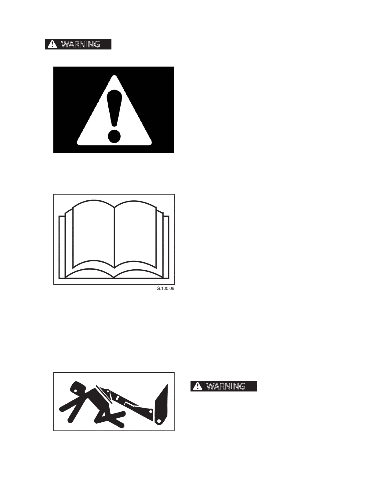
Do not operate this machine without reading and understanding this operator’s
SAFETY ALERT SYMBOL
Read all safety messages.
To avoid personal injury and/or property damage, follow safety messages.
OPERATOR PREPARATION
Operator must be fully trained, qualied, and authorized to operate this machine. Before operating
this machine, operator must know the location and
purpose of
• controls
• indicator lights
• instruments
• safety and instruction decals
(See Section 2, Safety Decals.)
AVOID CONTACT WITH STABILIZERS
Coming into contact with
stabilizers can cause serious personal injury or
death.
Clear all personnel from work area before raising or
lowering stabilizers.
2410
G.043.03
11
1111
Page 12

GENERAL SAFETY
WARNING
WARNING
BATTERY SAFETY
sive gases that can cause severe personal injury or
death.
Battery acid is poisonous and can cause severe
burns. If acid is taken internally, call a physician
immediately. If acid contacts skin or clothing, ush
with water immediately. Keep batteries away from
children.
Battery posts, terminals, and related accessories
contain lead and lead components, chemicals
known to the State of California to cause cancer
and reproductive harm. Wash hands after handling.
Keep sparks, ames, and cigarettes away from batteries. Ventilate properly when charging or using
batteries in enclosed space. Always shield eyes
with goggles and wear a face shield when working
near batteries. Do not lean over batteries during
this operation. Always connect positive (+) to positive (+) and negative (-) to negative (-). For further
instructions, see Jump Starting Battery in Section
6, Operation. If battery acid contacts eyes, ush
them with water for 15 minutes and seek immediate medical attention.
Batteries produce explo-
Never charge a battery or jump start engine if battery is frozen. Warm battery to 60°F (16°C) or it may
explode. Be sure vent caps are tight. When jump
starting from another machine, be sure machines
do not touch. This machine has a 12-volt starting
system. Use equal voltage for jump starting.
CONTROL SHUT OFF LEVER
Accidental movement
of turntable or booms can cause serious personal
injury or death.
Before leaving cab, lift control shut o lever to disengage hydraulic pilot circuit and to free door entry/exit
path.
2410
12
1111
Page 13
GENERAL SAFETY
DANGER
WARNING
ELECTRIC LINES
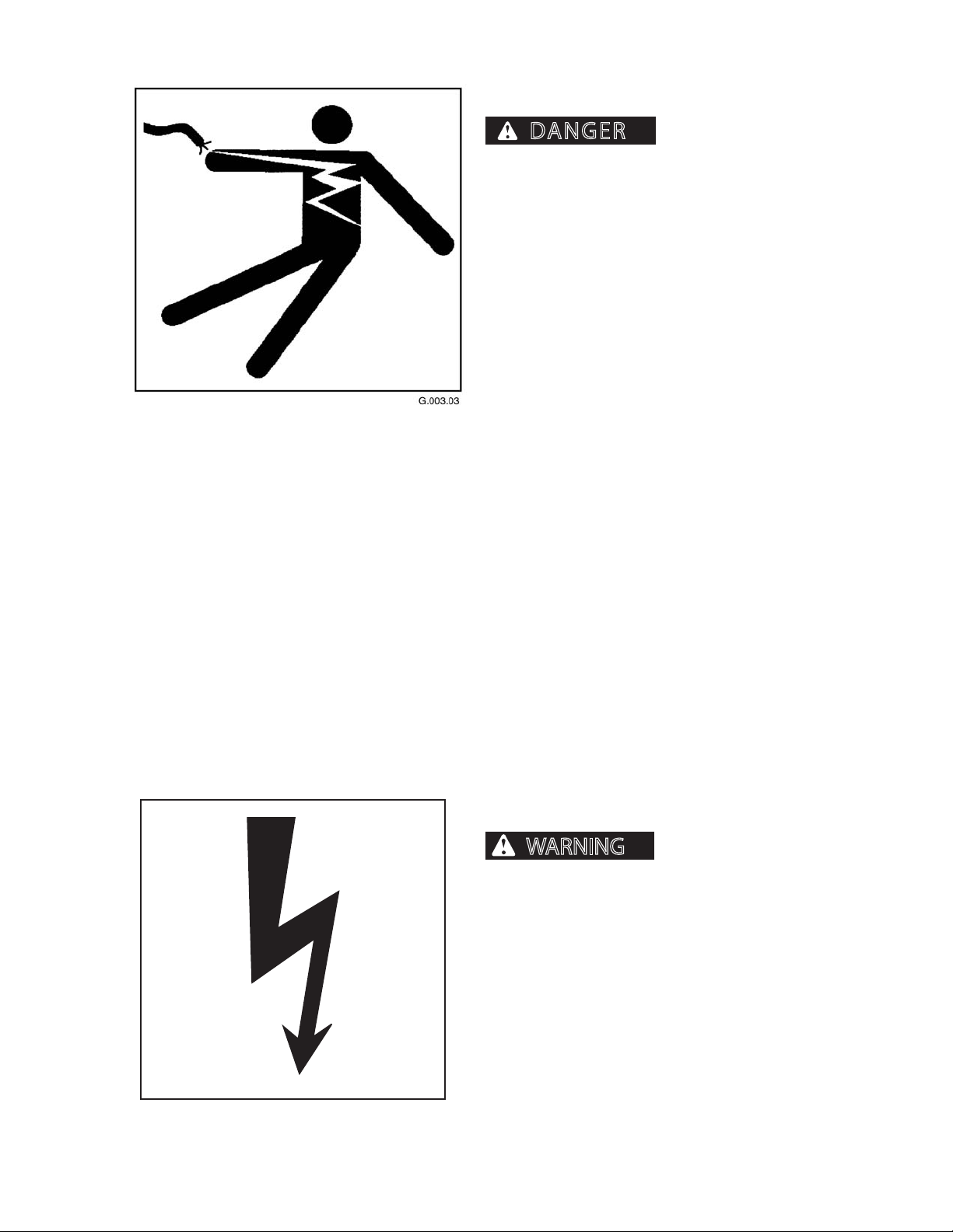
DEATH WILL RESULT FROM CONTACT WITH ELEC
TRIC LINES.
Never move any part of machine or load closer
than 10 feet plus twice the line insulator length to
electric lines. A line insulator is what connects an
electric line to an electric pole.
For example, if a line insulator is 6 inches long,
operator must stay at least 10 feet plus twice the
line insulator length (2x6 =12 inches or 1 foot) from
electric line, which means machine must stay at
least 11 feet from the electric line.
If machine touches an electric line, stay inside the
cab. Carefully move machine or load away from
electric line, without pulling the line down.
DO NOT allow anyone else to touch machine while
it is touching an electric line. If machine cannot be
moved away from the electric line without pulling
line down, have someone contact the utility company to disconnect power from line. If this is not
possible, or if machine begins to burn, jump away
from machine to the ground with both feet together, in one smooth jump. Do not run or walk away
from machine. Jump with feet together (“bunny
hop”) away from machine. DO NOT touch machine
and ground at the same time or else electricity in
the line will go through your body. Get away from
machine after jumping.
SERIOUS INJURY OR
Notify the utility company immediately. DO NOT
let anyone near the machine while it is touching an
electric line.
ELECTRICAL STORM
Electrical storms (lightning) can cause severe personal injury or death.
When lightning is striking in the vicinity of the
machine, the operator should NEVER attempt the
following procedures:
Mount the machine
Dismount the machine
If you are in the operator’s station during an electrical
storm, stay in the operator’s station. If you are on the
ground during an electrical storm, stay away from the
vicinity of the machine.
2410
13
1111
Page 14
GENERAL SAFETY
CAUTION
WARNING
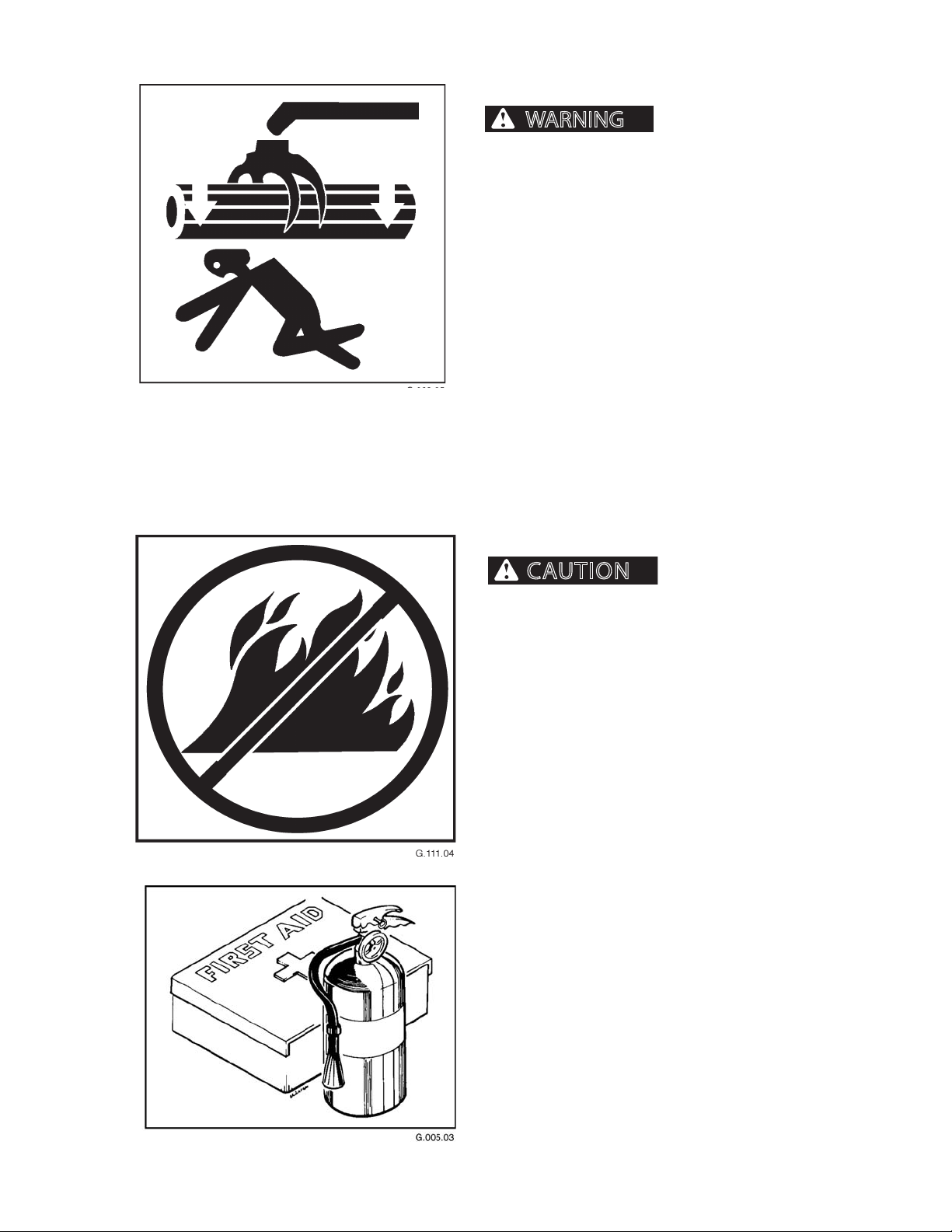
FALLING OR SWINGING LOGS
booms, or attachments can cause severe personal
injury or death.
Never operate the boom, attachment or load over or
near personnel.
Falling or swinging logs,
G.111.04
FIRE PREVENTION/FIRST AID
injury and/or machine damage.
Keep machine clean. Forest debris, rags, and trash will
cause res. Remove all debris, rags, and trash from
machine, especially around engine and hydraulic
components.
Repair all hydraulic and fuel leaks immediately. Do not
operate machine with hydraulic or fuel leaks.
Fire prevention beats re ghting. Remove debris from
all compartments after every 8 hours of operation, or
more often, if warranted by working conditions.
Install a rst-aid kit in the cab.
Properly maintain rst-aid kit and re extinguisher. Follow instructions provided with them.
Fires can cause personal
2410
14
1111
Page 15
GENERAL SAFETY
WARNING
WARNING
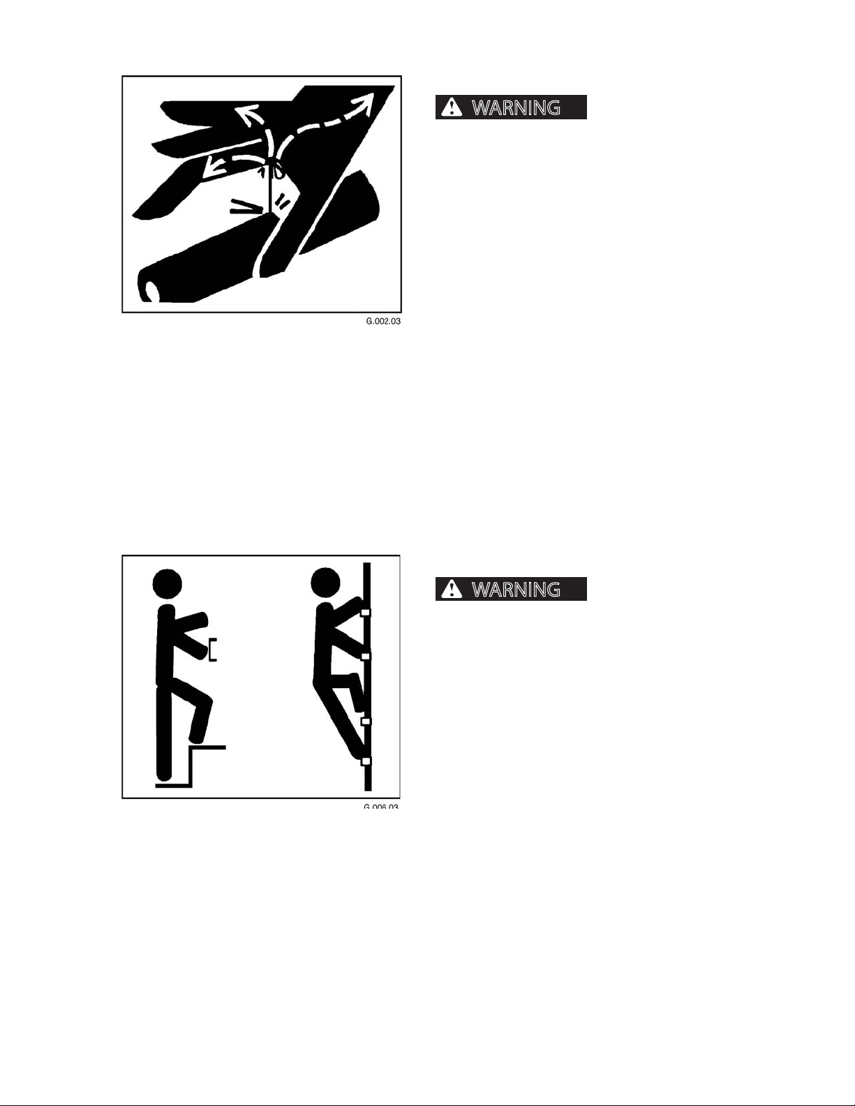
FLUIDS UNDER PRESSURE
pressure can penetrate skin and cause severe
personal injury or death. Wear eye and personal
protection equipment (PPE)!
Always use a board or cardboard when checking oil
hoses, lines, and ttings for leaks, cracks, or defects.
Be sure all clamps are in their proper position and
torqued as required and specied. Be sure hoses are
not twisted or touching parts.
DO NOT use hands to search for leaks. Escaping uids
can penetrate skin and enter the bloodstream. Before
disconnecting lines, relieve all pressure.
DO NOT apply pressure to a damaged line, hose, or
tting.
If ANY uid is injected into the skin, seek medical attention immediately. A serious infection or reaction
can result without proper medical treatment.
Fluids escaping under
HAND HOLDS AND STEPS
Slips and falls can cause
severe personal injury or death.
Use provided hand holds and steps while maintaining at least 3 points of support (1 foot and 2 hands
or 2 feet and 1 hand) when getting on and o machine. Face machine when getting on and o of it.
Never use controls as hand holds. Never use steering wheel as a hand hold. Moving the steering
wheel from its center position will COMPLETELY
turn machine right or left.
DO NOT mount machine if hand rails or steps are
broken or missing. Get them repaired rst.
DO NOT jump on or o machine unless it has
touched a live electrical wire and it must be exited.
Ensure rm foot position when getting on and o
machine. Be careful of slippery conditions on platform, steps, and hand holds when getting on and
o machine.
Remove oil, grease, mud, ice, etc. before mounting
or dismounting machine.
2410
To prevent slips and falls, replace skid-resistant material if it is worn, damaged or missing.
15
1111
Page 16
GENERAL SAFETY
WARNING
WARNING
HAND SIGNALS
vere personal injury or death.
Know and use the hand signals required for particular
jobs.
Know who has the responsibility for signaling.
Accidents can cause se-
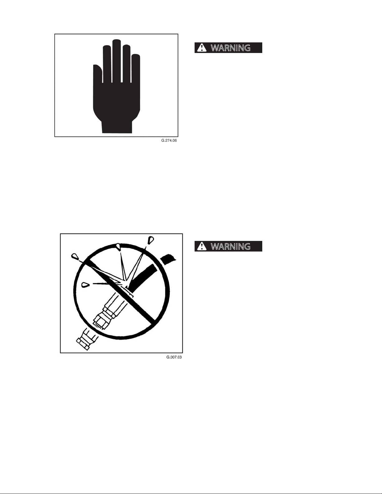
HOSES AND FITTINGS
Mismatched brands or
types of hoses and ttings can blow apart and
cause severe personal injury or death.
DO NOT interchange brands or types of hoses
and ttings.
DO NOT install a tting from one manufacturer on a
hose from a dierent manufacturer.
DO NOT install crimp ttings on hoses meant for reusable ttings.
Wear eye and personal protection equipment (PPE)!
Always use a board or cardboard when checking oil
hoses, lines, and ttings periodically for leaks, cracks or
defects. Be sure all clamps are in their proper position
and torqued as required and specied. Be sure hoses
are not twisted or touching parts.
2410
16
1111
Page 17
GENERAL SAFETY
WARNING
WARNING
NO RIDERS ON MACHNE
from machine or be injured by movement of machinery, causing severe personal injury or death.
Do not allow riders on any machine that is operating
or moving.
Machine riders can fall
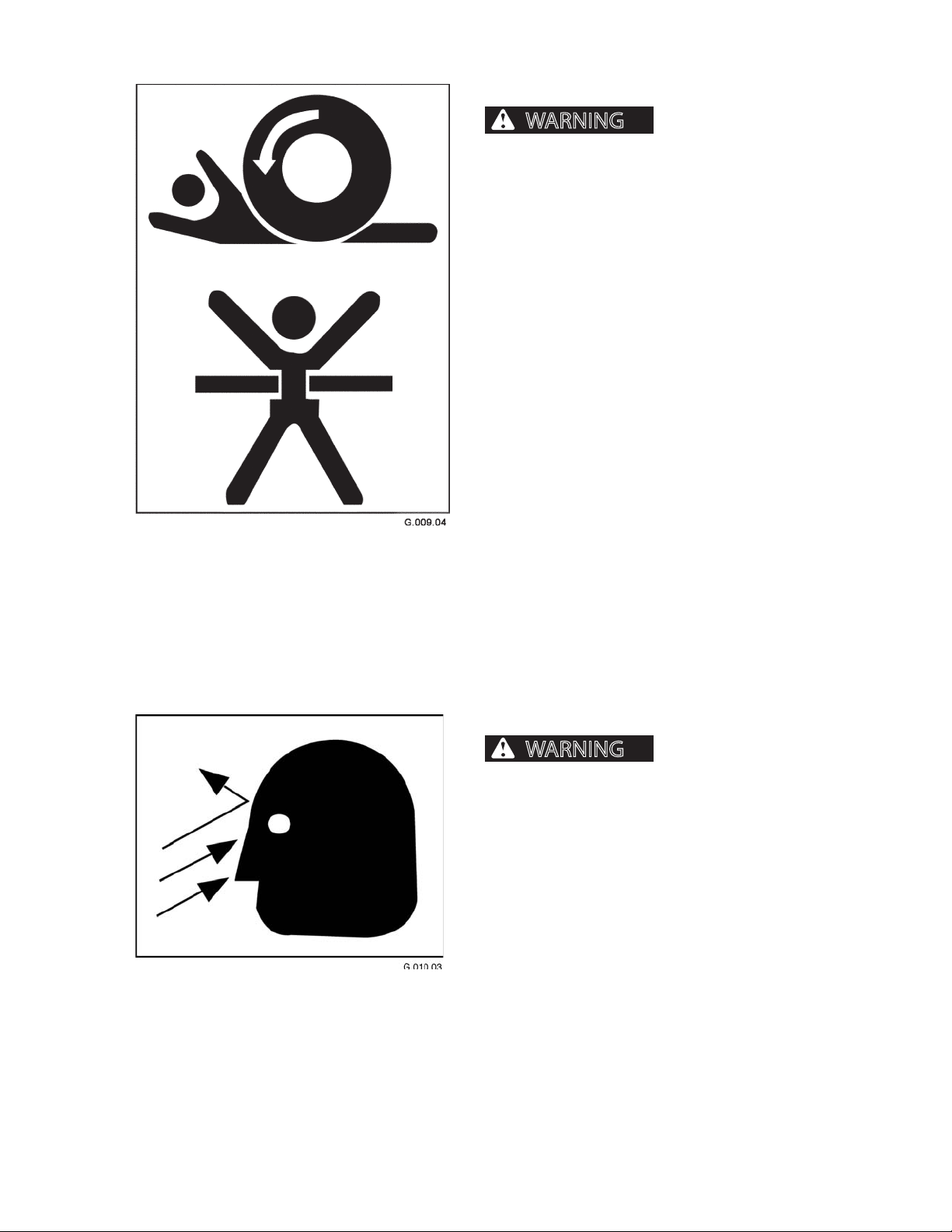
OPERATOR SAFETY
Flying debris, tree limbs,
and/or other material can cause severe personal
injury or death.
When operating machine:
1. Cab door must stay closed.
2. Window material and/or cab guarding MUST be in
place.
3. All cab openings (front, side, and rear) MUST be
covered with window material (no glass) and/or
protective screen.
4. Window guarding MUST be locked
in place.
2410
17
1111
Page 18
GENERAL SAFETY
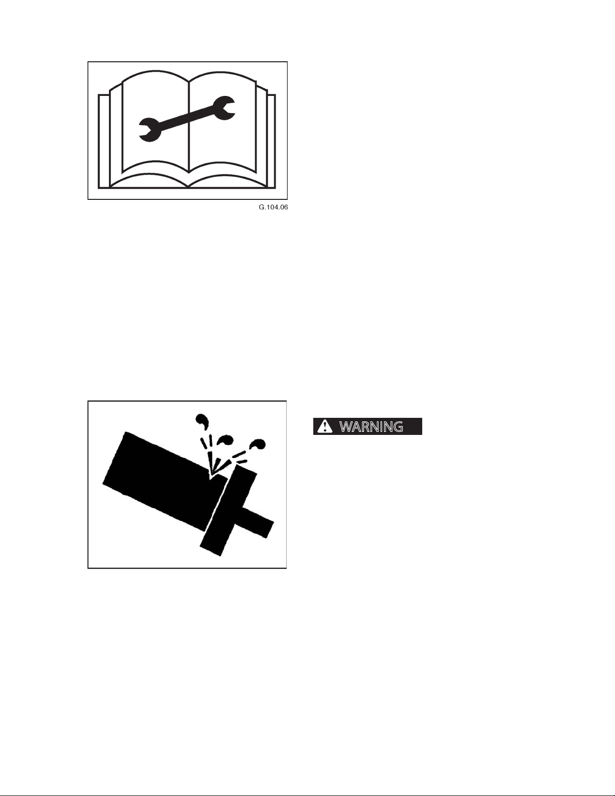
WARNING
PRACTICE SAFE MAINTENANCE
Understand service procedures before performing
maintenance. When performing maintenance, keep
area around machine clean and dry.
DO NOT service machine while it is moving. Keep away
from power-driven parts. Lower attachment to the
ground. Disengage power. Shut engine down. Move
controls in all directions to relieve hydraulic pressure.
Remove key from ignition. Allow machine to cool
down.
Support all raised equipment.
Keep all machine parts in good condition, and be sure
parts are properly installed. Repair damage immediately. Repair all hydraulic and fuel leaks immediately.
Replace worn or broken parts. Remove any buildup of
grease, oil, or debris.
Disconnect battery ground cable (-) before adjusting
the electrical system.
PRESSURE SETTINGS
Excessive hydraulic pressure can cause component or structural failure,
which may result in severe personal injury or
death.
Wear eye and personal protection equipment (PPE)!
DO NOT exceed factory-adjusted pressure settings.
2410
18
1111
Page 19
GENERAL SAFETY
CAUTION
WARNING
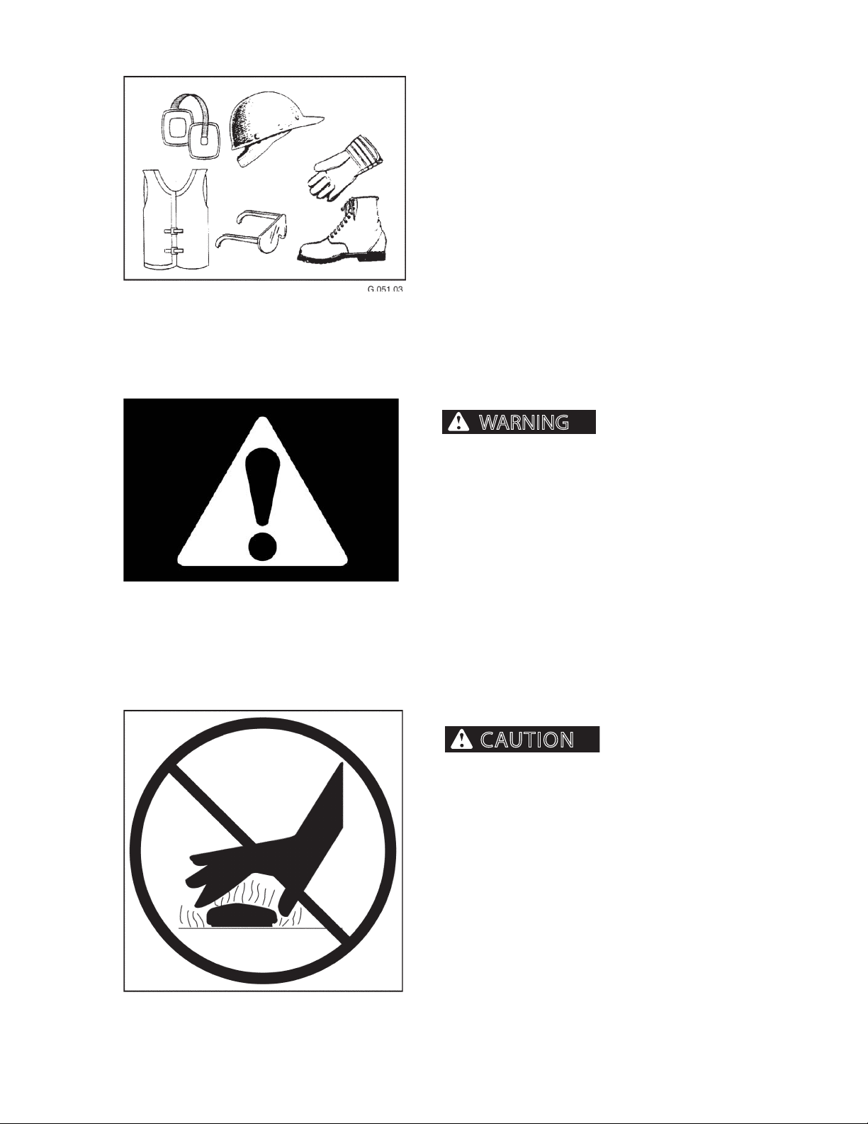
PROTECTIVE CLOTHING
Wear OSHA or local governing body-approved protective clothing when working on or near this machine,
such as
• ear protection • hard hat
• gloves • orange vest
• goggles • steel-toed shoes
Wear snug, protective clothing that is belted where
required.
Remove jewelry before working on or near this machine.
PROTECTIVE DEVICES/EQUIPMENT
ignorance of protective equipment or devices can
cause severe personal injury or death.
Misuse, interference and
Alarms, re prevention equipment, ROPS/FOPS/OPS,
and other safety equipment is installed on machine for
your protection.
Never ignore, disconnect, disable or modify protection
equipment in any manner.
RADIATOR CAP
tem can cause scalding burns.
Wear eye and personal protection equipment (PPE)!
Do not remove radiator cap unless engine is cool.
Allow system to cool. Remove cap slowly to relieve
pressure before removing completely.
Pressurized cooling sys-
2410
19
1111
Page 20
GENERAL SAFETY
WARNING
WARNING
NOTICE
DANGER
G.020.05
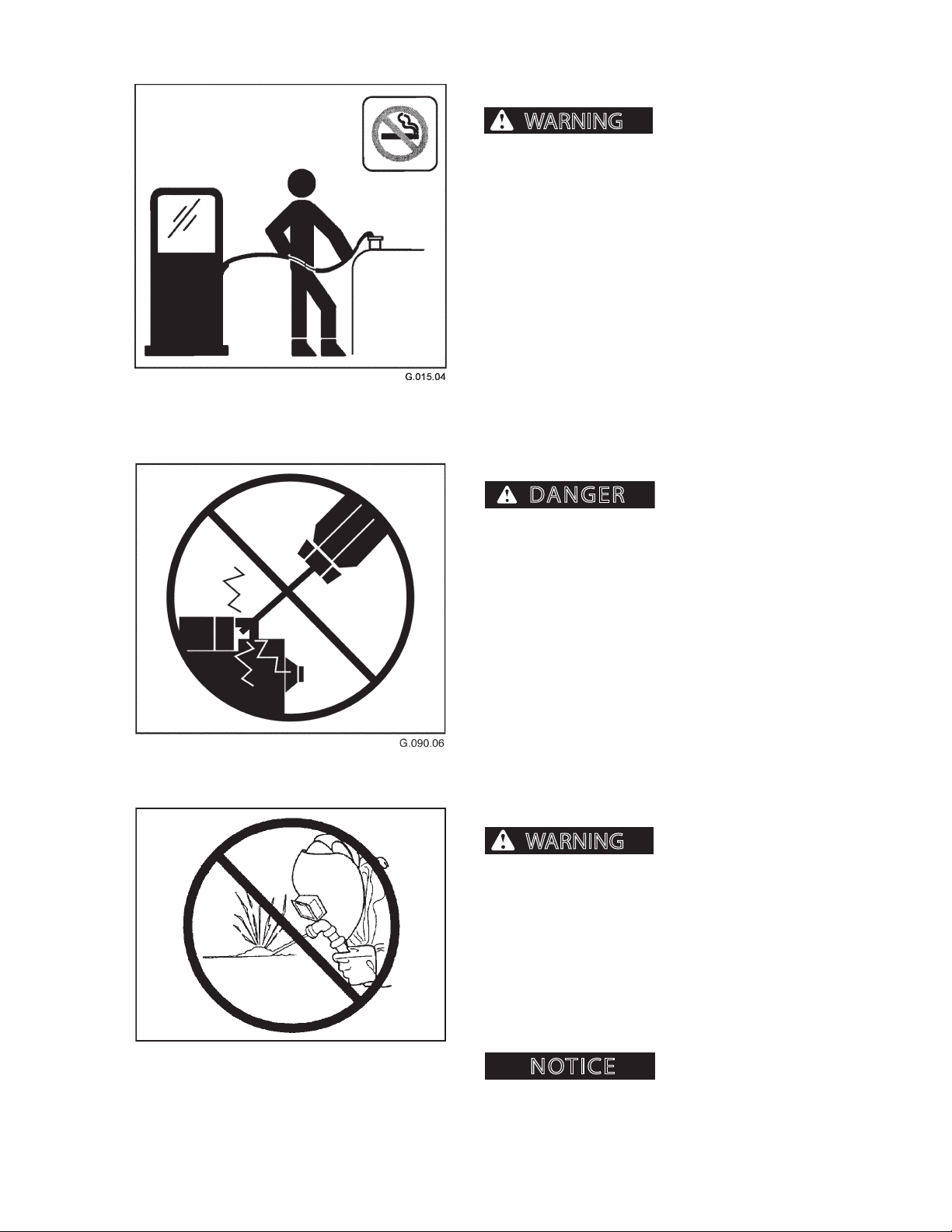
REFUELING
cause severe personal injury or death.
Handle fuel with care. It is highly ammable.
DO NOT refuel machine while smoking or when near
open ame or sparks.
Always stop engine before refueling. Fill fuel tank outdoors. Prevent res by keeping machine clean of trash,
grease, and debris. Always clean up spilled fuel.
STARTER CIRCUITRY
Fires and explosions can
MACHINE WILL START IN
GEAR IF START CIRCUITRY IS BYPASSED.
Do not attempt to start machine engine by shorting
starter circuit across starter terminals. Doing so may
cause unintended machine movement which could
result in severe personal injury or death and serious
machine and/or property damage.
UNAUTHORIZED WELDING
Unauthorized welding
can cause structural failure and/or severe personal
injury or death.
DO NOT weld on any structural member.
Any unauthorized welding or repair will void
the warranty.
2410
Once authorized, be sure to turn battery disconnect
master switch OFF and place welding ground (stinger)
as close to weld site as possible. Do not allow weld current to pass through bearings or pivot points.
Unauthorized welding can
cause damage to the electrical system.
110
1111
Page 21

GENERAL SAFETY
WARNING
UNSTABLE PLATFORM
cause severe personal injury or death.
Lower all stabilizers before operating machine.
Unstable platform can
2410
111
1111
Page 22

GENERAL SAFETY
2410
112
1111
Page 23

SAFETY DECALS
NOTICE
SAFETY DECALS
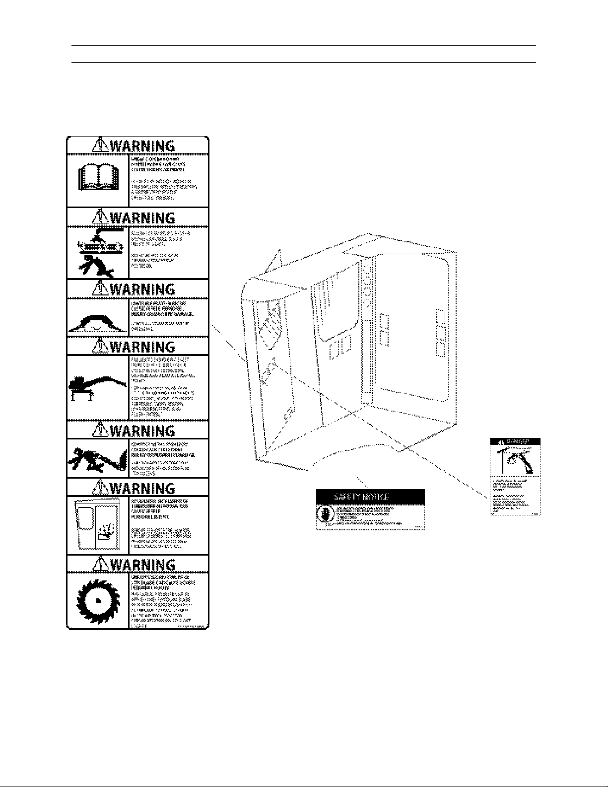
The following safety decals are located in positions on the machine as continual reminders of HAZARDS. Serious
injury or property damage can occur if safety instructions are not followed.
Keep all safety decals clean and readable. Use soft cloth, water, and soap to clean decals if they are too dirty to
read. DO NOT clean safety decals with solvent. Solvent can damage them.
Replace safety decals immediately if they are damaged, missing, or hard to read. Contact an authorized dealer
for replacement safety decals. Authorized dealers will provide free replacement safety decals if you give them a
valid serial number for your machine.
If you replace a part that has a safety decal on it, apply a new safety decal to the replace-
ment part. Before putting a new decal on the machine or part, be sure the surface where the decal will be mounted is
clean and dry.
2410 2-1 1111
Page 24

SAFETY DECALS
LOADER DECALS
2410 2-2 1111
Page 25
SAFETY DECALS
CAB DECALS
2410 2-3 1111
Page 26
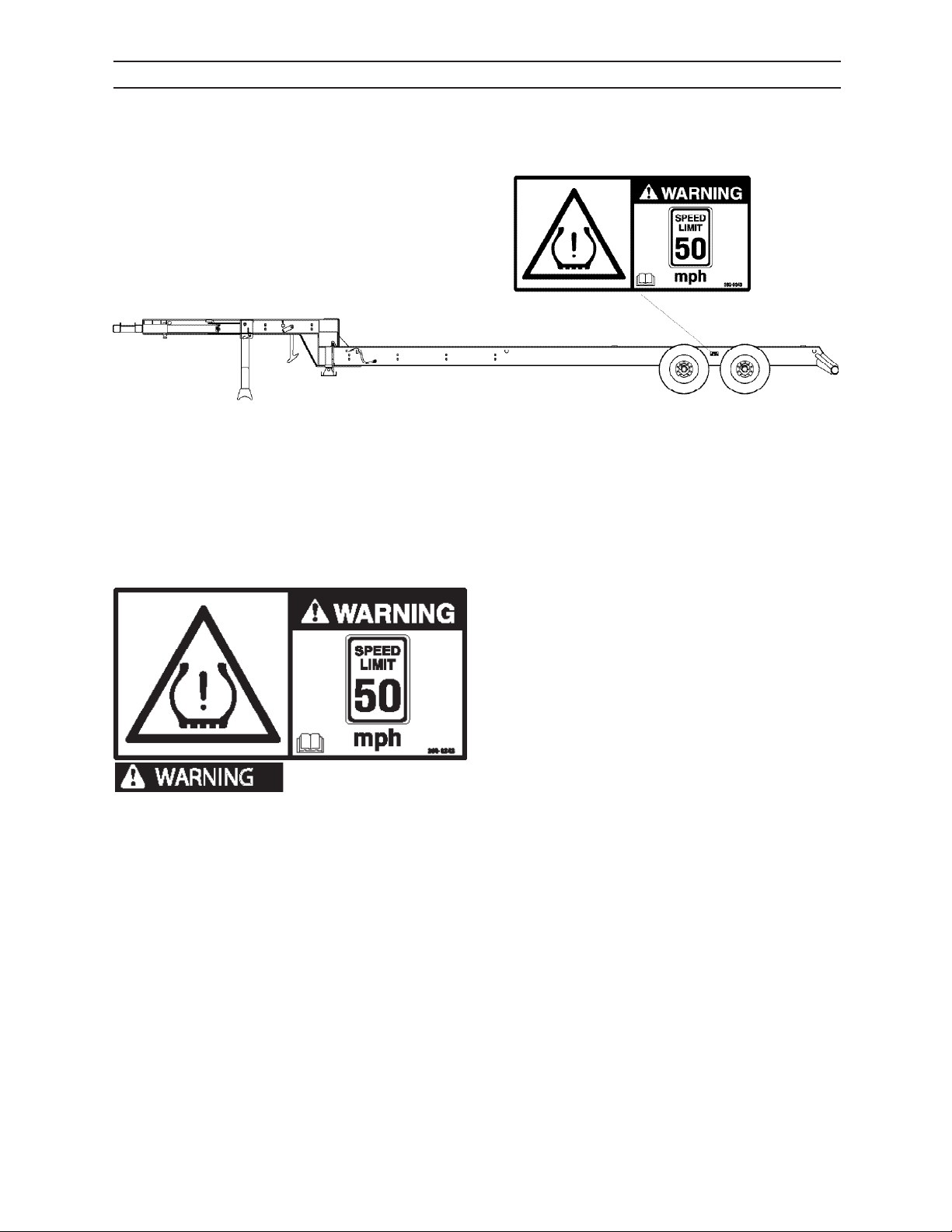
SAFETY DECALS
TMS TRAILER DECALS
Tire Malfunction
This warning is located on each side of the machine
trailer.
Do not exceed speeds of
50 mph when transporting machine. Tire malfunction can occur resulting in serious personal injury
or death.
2410 2-4 1111
0511
Page 27
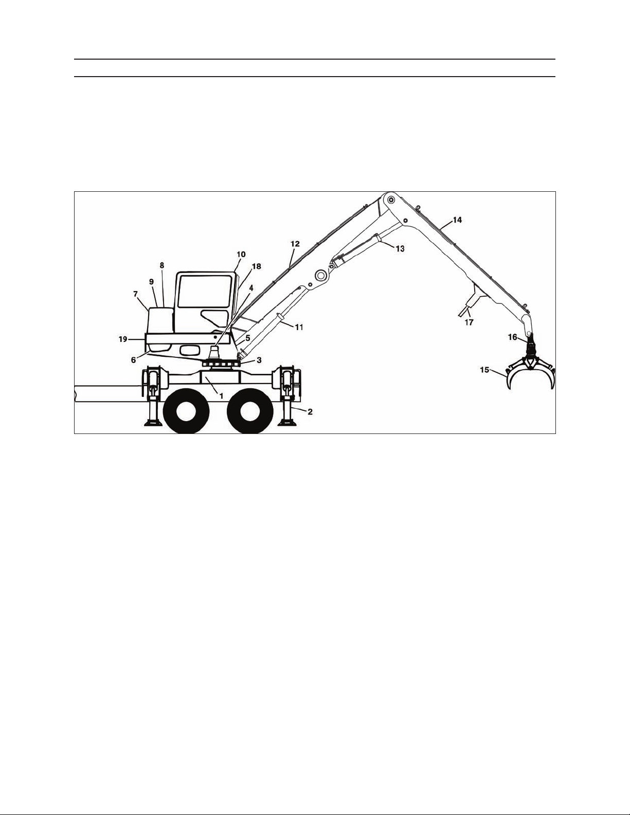
COMPONENT TERMINOLOGY
COMPONENT TERMINOLOGY
LOADER
1. Subframe assembly
2. Stabilizer
3. Swing bearing
4. Swing motor
5. Upper frame assembly
6. Hydraulic pump assembly
7. Hydraulic oil reservoir
8. Hydraulic oil lter
9. Oil cooler
2410 3-1 1111
10. Cab
11. Main boom cylinder
12. Main boom
13. Stick boom cylinder
14. Stick boom
15. Grapple
16. Grapple knuckle
17. Stationary heel (option)
18. Operator protection guard
19. Turntable assembly
Page 28
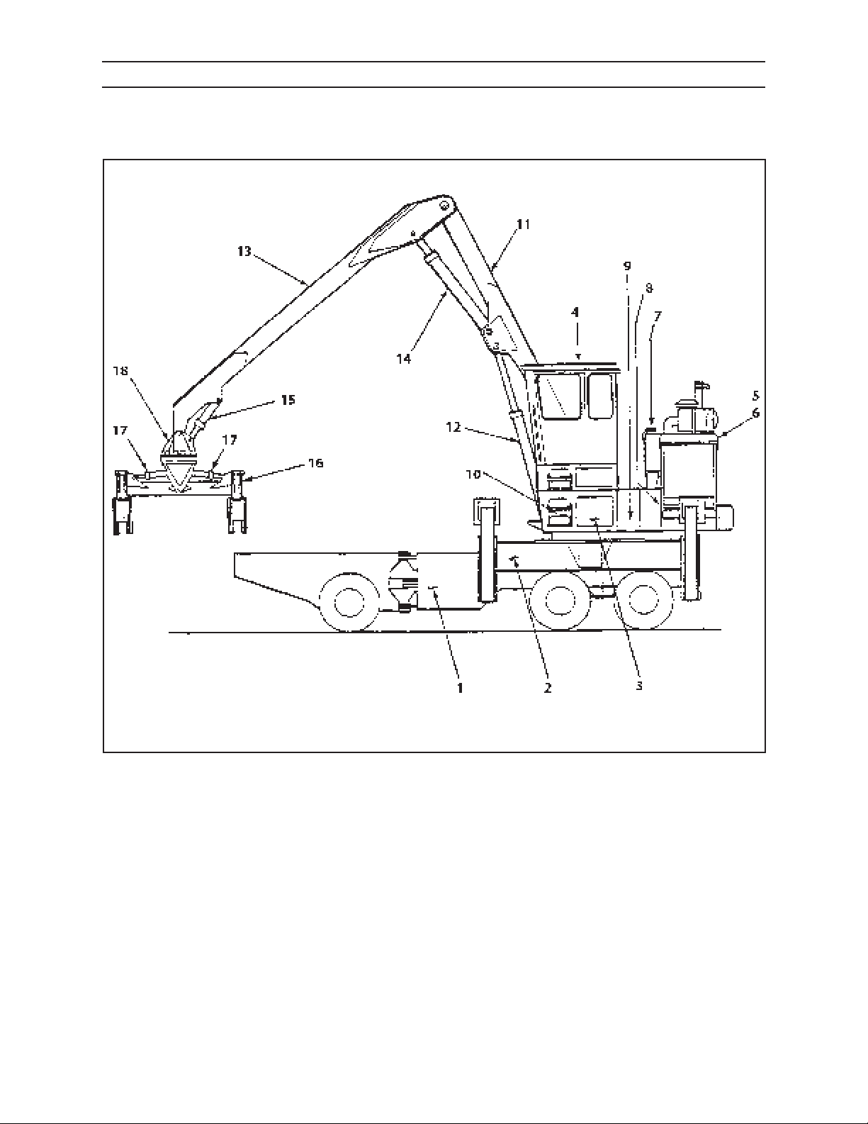
COMPONENT TERMINOLOGY
LOADER
1. SAP Chassis
2. Subframe
3. Turntable
4. Operator’s Cab
5. Engine Compartment
6. Hydraulic Pump & Drive
7. Hydraulic Oil Reservoir
8. Fuel Tank
9. Control Valves
10. Swing Motor (other side)
11. Main Boom
12. Main Boom Cylinder
13. Stick Boom
14. Stick Boom Cylinder
15. Tilt Cylinder
16. Grapple
17. Grapple Tilt Cylinder
18. Grapple Head
2410 3-2 1111
Page 29
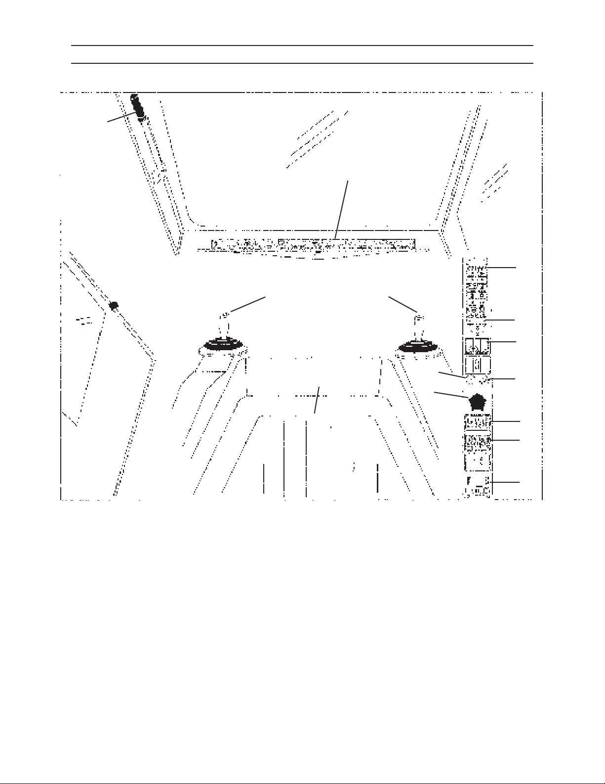
CONTROLS AND INSTRUMENTS
CONTROLS AND INSTRUMENTS
OPERATOR’S CAB
5
6
7
1. Operator’s Seat
2. Engine Throttle Control
3. Right Hand Joystick Control
4
3
8
9
14
1
10
2
11
12
13
G.023.03
8. Error Code Indicator Lights
9. Stabilizer Switches
10. Power Supply
4. Left Hand Joystick Control
5. Pilot Pressure Shuto Lever
6. Foot Control - Swing Pedal
7. Instrument Console
2410 1111
11. Washer/Wiper and Light Switches
12. A/C Heat/Defrost Switches
13. Heat Control Lever
14. Ignition
41
Page 30
CONTROLS AND INSTRUMENTS
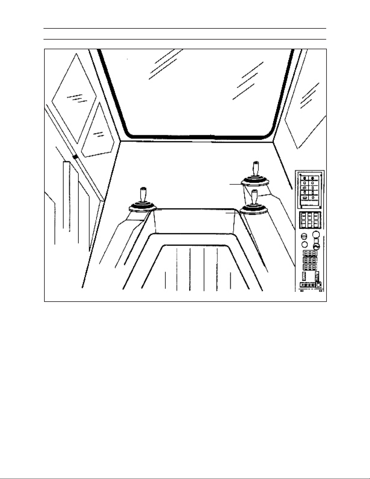
JOYSTICKS WITH PIPE HANDLE ATTACHMENT
3
1
1. Left hand Control - Stick, Swing & Jib
2. Rear Right Hand Control - Grapple
3. Front Right Hand Control - Steer &
Drive, Switch for Brake Control
2
2410
42
1111
Page 31
CONTROLS AND INSTRUMENTS
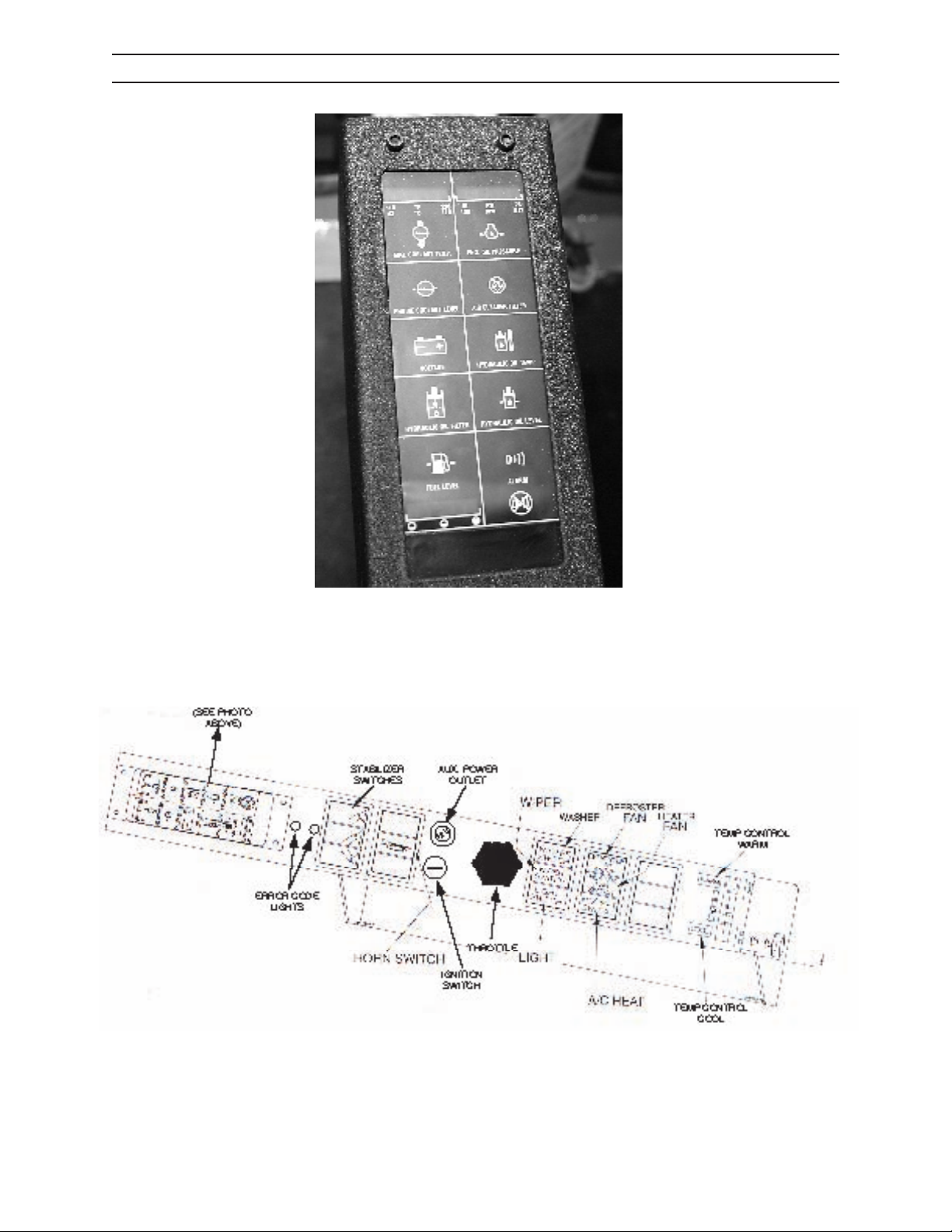
INSTRUMENT CONSOLE
Engine Coolant Temp
Engine Coolant Level
Voltage
Hydraulic Oil Filter
Fuel Level
Engine Oil Pressure
Air Cleaner Filter
Hydraulic Oil Temperature
Hydraulic Oil Level
Alarm
IMG.2414.
G.024.03
2410 1111
43
Page 32
CONTROLS AND INSTRUMENTS
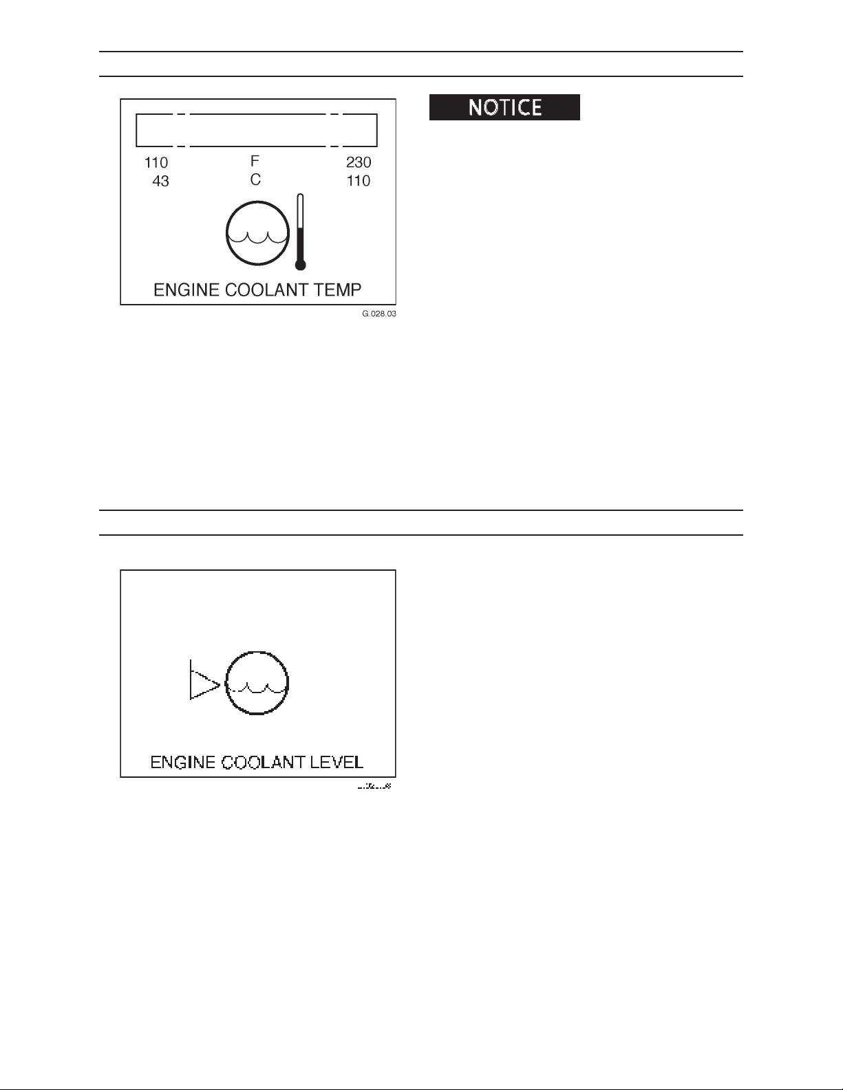
ENGINE COOLANT TEMPERATURE WARNING INDICATOR
Failure to reduce load with
engine coolant temperature warning indicator lit could
cause premature engine failure or damage.
If the engine coolant temperature reaches 210°F
(99°C), a warning indicator will light and an alarm will
sound. When this happens, shut engine down and
check for loose belts, coolant leakage, or a plugged
radiator.
LOW COOLANT WARNING INDICATOR
The low coolant warning indicator will light and an
alarm will sound when the coolant in the radiator is
low by approximately 1.25 gallons (4.72 L) from the
FULL level.
When the indicator lights, immediately shut engine
down, ll radiator with coolant (50 percent mixture or
clean, distilled water and ethylene glycol antifreeze),
and check for leaks and/or damage.
2410
44
1111
Page 33
CONTROLS AND INSTRUMENTS
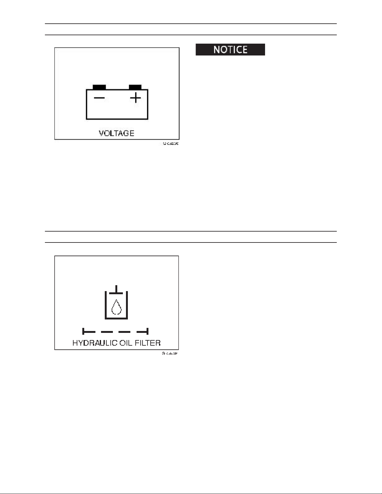
VOLTAGE WARNING IDICATOR
DO NOT operate engine if
voltage warning indicator is lit. Operating with voltage
too high or too low can cause electrical system damage.
If voltage is too high or too low, the voltage warning
indicator will light. Immediately shut engine down,
turn key to OFF position, and check electrical system
for improper charging.
HYDRAULIC OIL FILTER WARNING INDICATOR
The hydraulic oil lter warning indicator will light if
any of the hydraulic system lters become restricted or
plugged. Once lters are serviced, indicator light will
go o.
The indicator will light at initial start up until hydraulic
oil reaches normal operating temperature.
If indicator remains lit, oil is bypassing the return line
lter and going directly into the tank without being
ltered.
The lters should be changed immediately to prevent
damage to hydraulic components. See Scheduled/Periodic Maintenance Services Section, for lter replacement instructions.
2410 1111
45
Page 34
CONTROLS AND INSTRUMENTS
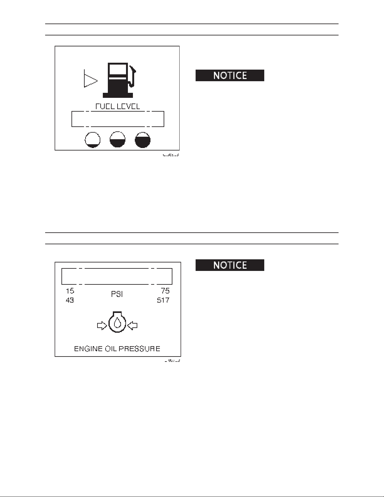
FUEL GAUGE
The fuel gauge indicates the amount of fuel in the fuel
tank. A warning indicator will light if fuel level drops
below .17 percent capacity.
engine to run out of fuel. Doing so will cause engine damage.
. DO NOT allow a diesel
ENGINE OIL PRESSURE WARNING INDICATOR
. If no oil pressure is indicated
within 10 to 15 seconds at start up, stop engine and
check the lubricating oil system. Oil pressure does not
guarantee a sucient amount of oil in the engine oil pan.
Check engine oil level by observing level on the engine oil
dipstick.
The engine oil pressure warning indicator will light
if engine oil pressure drops below 15 psi (103 kPa).
When this happens, shut engine down and check for
leaks. Refer to the engine operator’s manual for more
information.
2410
46
1111
Page 35
CONTROLS AND INSTRUMENTS
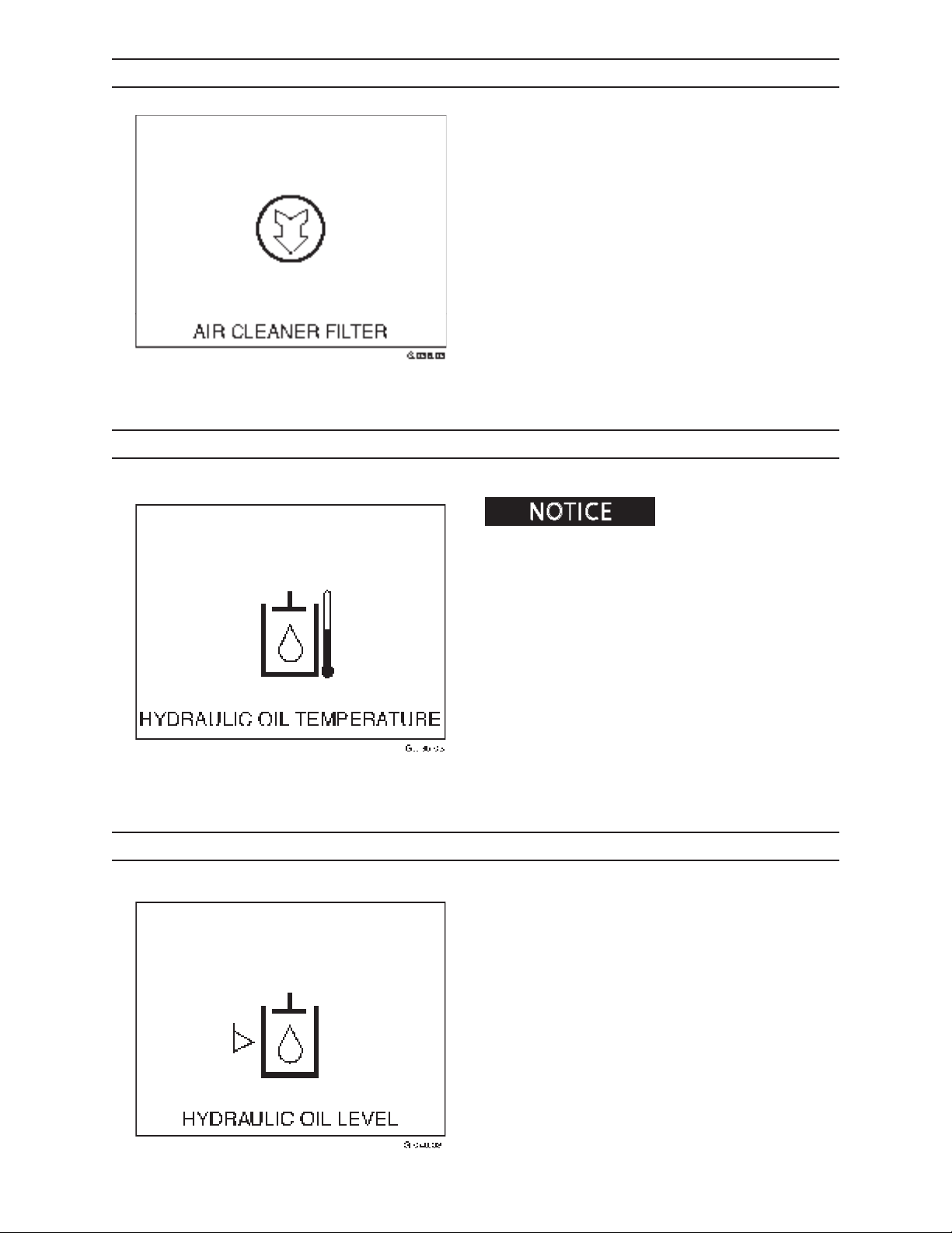
AIR CLEANER WARNING INDICATOR
The air lter warning indicator will light when the
engine air lter is plugged and requires cleaning or
replacement. Once air lter is serviced, indicator light
will go o.
In high humidity conditions, indicator may register a
false reading.
See Scheduled/Periodic Maintenance Services Section
or proper air lter maintenance.
HYDRAULIC OIL TEMPERATURE WARNING INDICATOR
. Possible pump or hydraulic
system damage can occur if operating for an extended
period of time when hydraulic oil temperature warning
indicator is lit.
A warning indicator will light and an alarm will sound
if the hydraulic oil temperature reaches 200°F (93°C).
If this happens, shut engine down immediately and
check for a plugged oil cooler or leaks.
LOW HYDRAULIC OIL WARNING INDICATOR
The low hydraulic oil warning indicator will light when
the hydraulic oil level becomes too low.
Fill reservoir immediately to prevent damage to hydraulic components.
To ll hydraulic reservoir, refer to Scheduled/Periodic
Maintenance Services Section.
2410 1111
47
Page 36
CONTROLS AND INSTRUMENTS
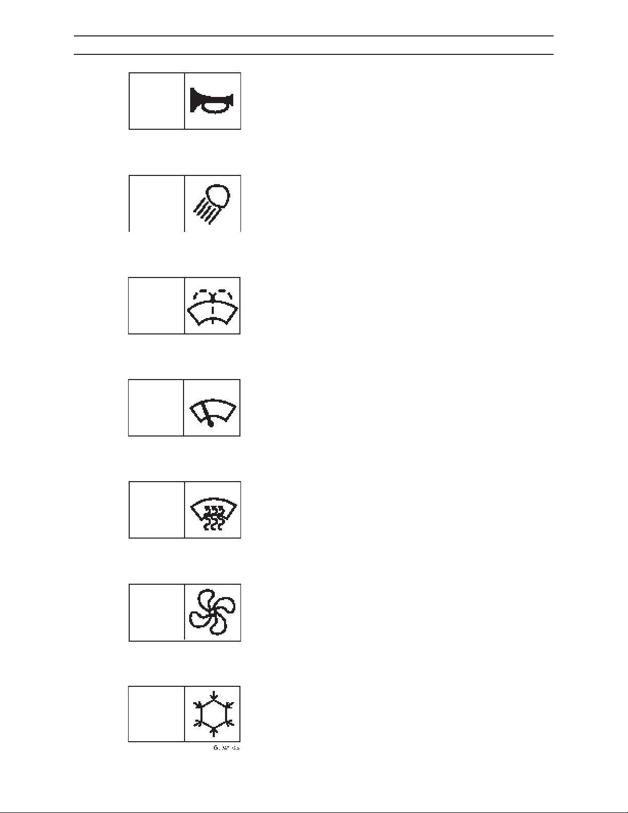
SWITCH PANEL
HORN SWITCH
Press switch to sound horn.
WORK LIGHT SWITCH
Press switch to turn on work lights.
WINDSHIELD WASHER SWITCH
Press switch to dispense windshield wiper uid. Wipers
will operate as long as switch is depressed.
WINDSHIELD WIPER SWITCH
Two-position switch controls speed of wiper motor.
Top position is OFF; middle position is low speed; bottom position is high speed.
DEFROSTER FAN SWITCH
Press switch to start defroster fan.
HEATER/AC FAN SPEED SWITCH
Two-position switch controls speed of fan motor. Top
position is OFF, middle position is low speed; bottom
position is high speed.
2410
HEAT/AC MODE SWITCH
Two-position switch controls heat/AC mode. Top position is heat mode; middle position is OFF, and bottom
position is AC.
48
1111
Page 37
CONTROLS AND INSTRUMENTS
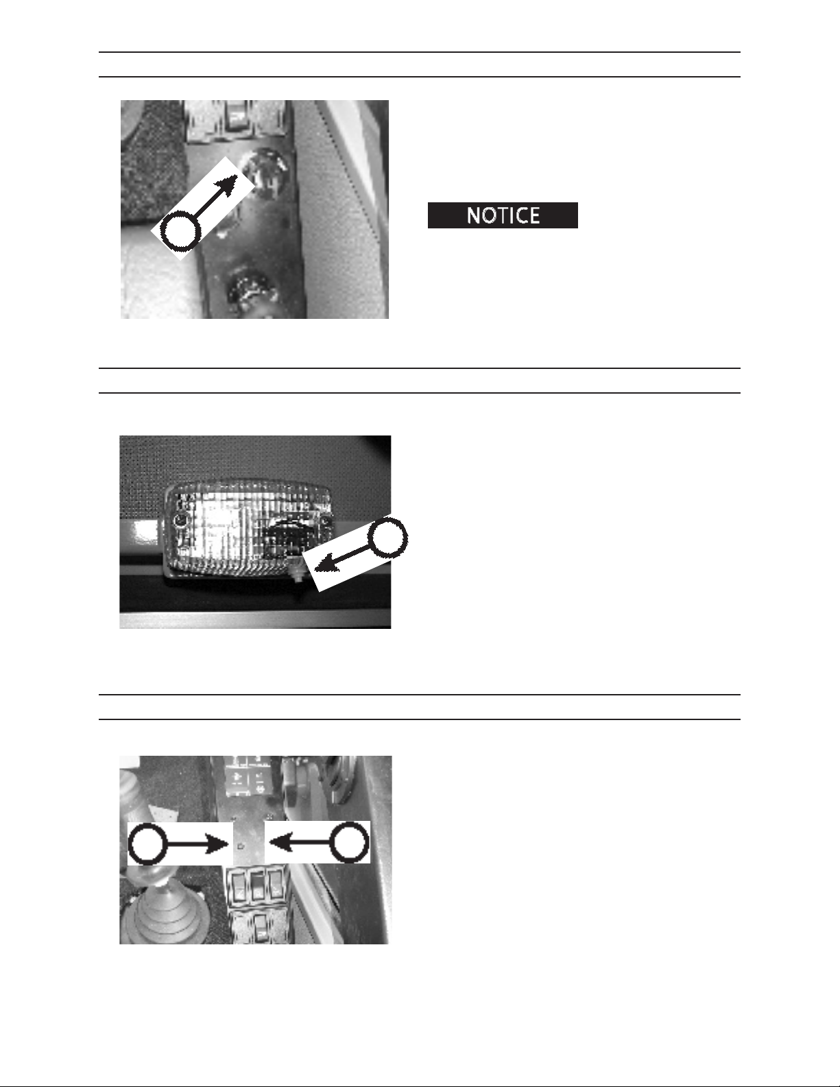
IGNITION SWITCH
Turn key in ignition switch (A) to ACC for power to the
electrical components.
Turn key to ON position for power to the starter and
electrical components.
Turn key OFF to shut engine down.
A
Before leaving machine, be
sure key is in OFF position to prevent battery drain.
Remove key so machine cannot be accidentally
started, or started by unauthorized personnel.
DOME LIGHT
Press the button (B) to turn the dome light ON or OFF.
B
D
IMG.2432
ERROR CODE INDICATOR LIGHTS
The error code indicator lights (C and D) will ash
when engine problems exists. For specic information
on errors, refer to Operation Section.
C
2410 1111
49
Page 38
CONTROLS AND INSTRUMENTS
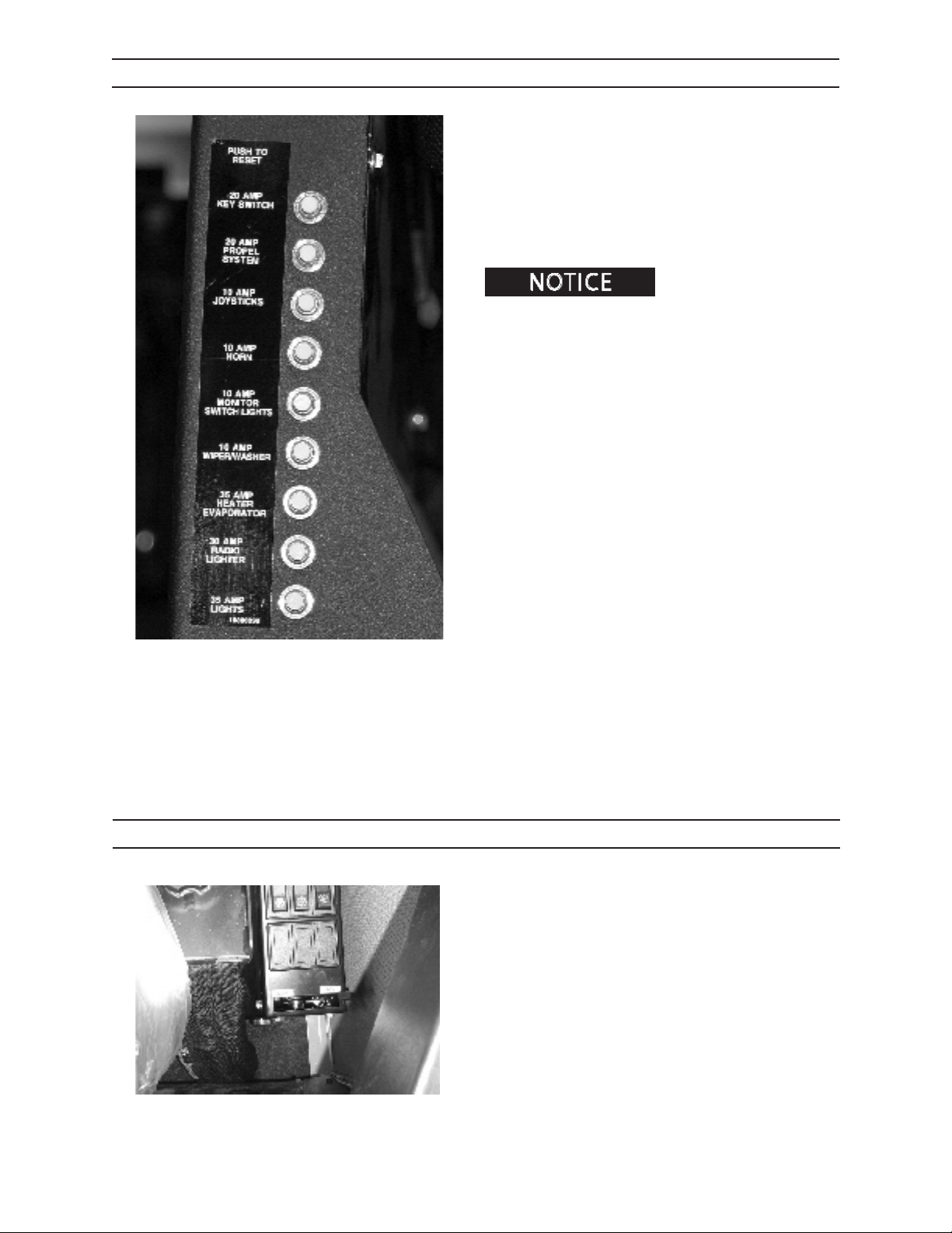
CIRCUIT BREAKERS
Circuit breakers protect an electrical circuit from current overload.
If an overload should occur, the circuit breaker will trip,
thus breaking the ow of current and prventing damage to the circuit.
To reset the circuit breaker, press the tripped breaker
to its original position.
quently, consult an authorized dealer for assistance.
If circuit breakers trip fre-
IMG.2490
HEAT CONTROL LEVER
Temperature in the cab is regulated by adjusting the
position of the heat control lever. For more heat, move
the lever toward the side labeled WARM.
For less heat, move the lever toward the side labeled
COOL.
2410
410
1111
Page 39
CONTROLS AND INSTRUMENTS
PILOT PRESSURE SHUT OFF
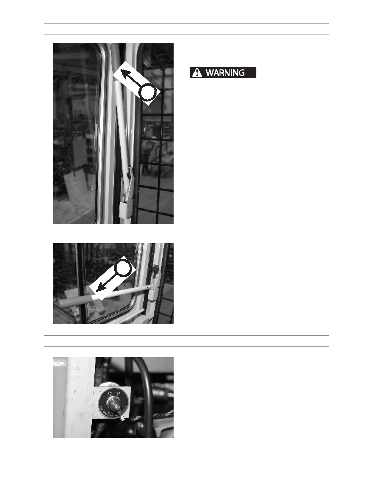
The cab is equipped with a lever to shut o pilot pressure to the joystick and foot pedal controls when the
operator exits the cab.
of turntable or booms can cause serious personal
A
injury. Before leaving cab, always push hydraulic
power shut o lever up and forward to disengage
hydraulic pilot circuit, and to free the door entry/
exit path.
PILOT PRESSURE DISENGAGED A
When the pilot shut o lever is in the UP position (A),
the pilot controls (joystick and foot pedal functions)
are disabled. Before exiting cab, always push the pilot
shut o lever up and forward to disable the pilot controls and to free the entry/exit path.
Accidental movement
IMG.2576
PILOT PRESSURE ENGAGED B
When the pilot shut o lever is in the DOWN position
B
IMG.2577
(B), pilot controls are operational. When down, the
lever blocks the cab door. The lever must be down to
operate the machine.
BATTERY DISCONNECT MASTER SWITCH
The battery disconnect master switch, located behind
the cab near the diesel fuel ll cap, is designed to prevent accidental starting of the engine during servicing,
to prevent accidental battery drain, and to help as a
vandal deterrent.
Turn switch OFF to shut o electrical system.
Turn switch ON to connect electrical system.
All systems will shut down if battery disconnect master
switch is turned OFF.
IMG.2385
2410 1111
411
Page 40
CONTROLS AND INSTRUMENTS
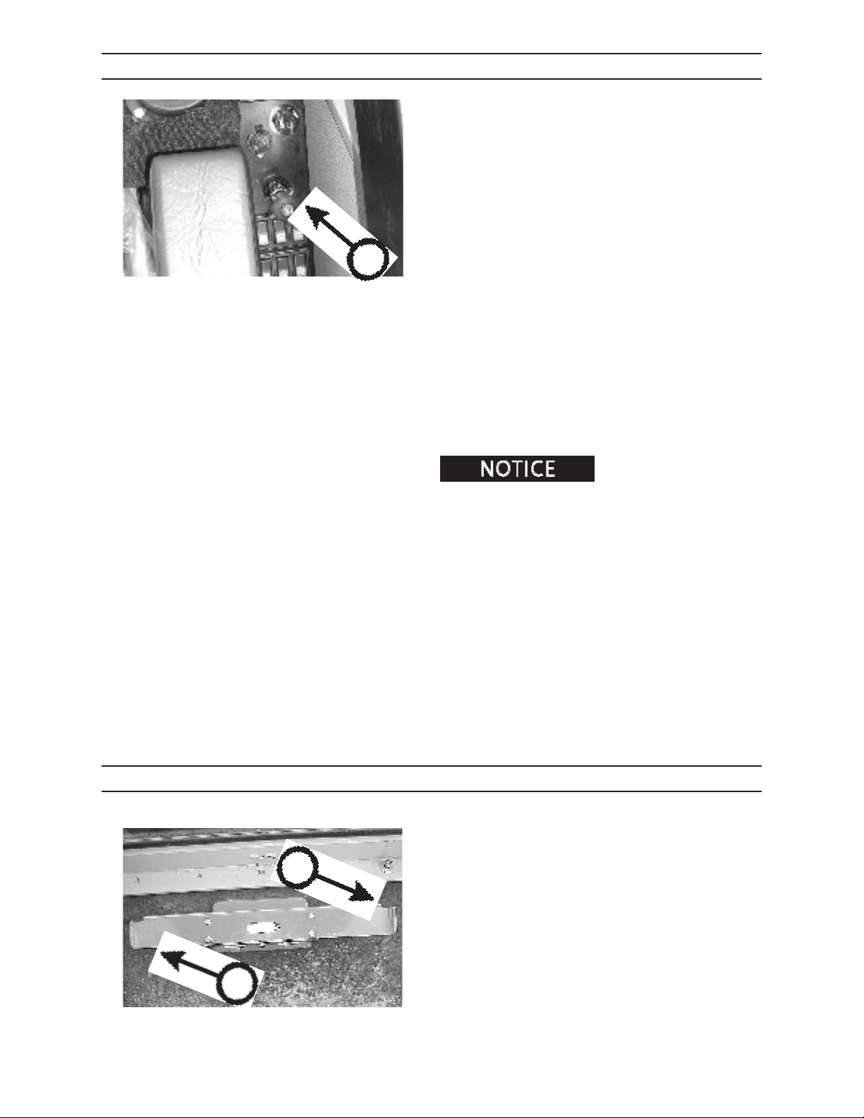
THROTTLE
Operate engine at FULL throttle.
Engine must run at full throttle because doing so
ensures
• proper cooling of engine and hydraulic system,
• proper volume and pressure of oil to hydrostatic
components; and,
• full oil ow to hydraulic circuits.
A
The throttle (A) controls governed engine speed from
low idle to full governed speed as follows:
Low idle rpm 900
Full load governed rpm 2400
INCREASING ENGINE SPEED
Turn knob clockwise to increase engine speed.
DECREASING ENGINE SPEED
Turn knob counterclockwise to decrease engine speed.
C
To return to IDLE, push
throttle knob in.
SWING PEDAL
Control the upper frame swing as follows:
Press LEFT side of pedal (B) to swing upper frame to
the left.
2410
B
001.03
Press RIGHT side of pedal (C) to swing upper frame to
the right.
412
1111
Page 41

A
CONTROLS AND INSTRUMENTS
LEFT JOYSTICK
LEFT HAND JOYSTICK
The left hand joystick (A) operates the main boom,
stick boom, and grapple as follows:
Push joystick lever forward (B) to lower main boom.
Push joystick lever back (C) to raise main boom.
Push joystick lever left (D) to open grapple jaws.
Push joystick lever right (E) to close grapple jaws.
G.077.03
D
B
E
C
G.086.03
2410 1111
413
Page 42
CONTROLS AND INSTRUMENTS
RIGHT JOYSTICK
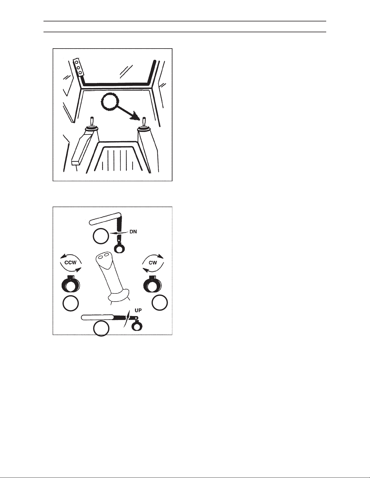
RIGHT HAND JOYSTICK
The right hand joystick (A) operates the stick boom
and grapple rotation as follows:
Push joystick lever forward (B) to lower stick boom.
Pull joystick lever back (C) to raise stick boom.
B
A
Push joystick lever left (D) to rotate grapple counterclockwise.
Push joystick lever right (E) to rotate grapple clockwise.
G.077.03
2410
D
C
E
G.087.03
414
1111
Page 43
CONTROLS AND INSTRUMENTS
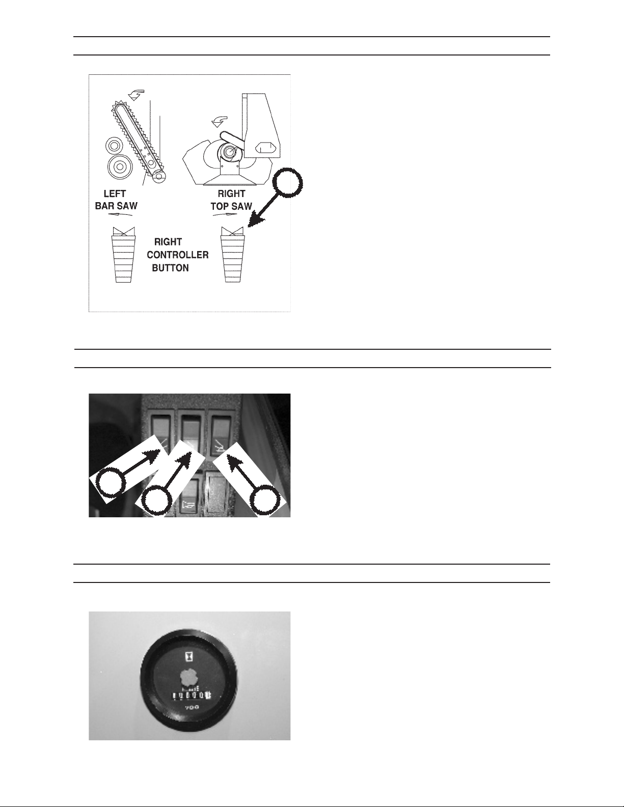
RIGHT JOYSTICK ROCKER SWITCH
The rocker switch on top of the right joystick (A)
activates the saw bar in and out of its storage housing,
and activates saw function.
Press the rocker switch LEFT to start the saw chain and
to activate saw bar function.
Press the rocker switch RIGHT to stop the saw chain
and to return the saw bar to storage housing.
A
G.089.03
B
C
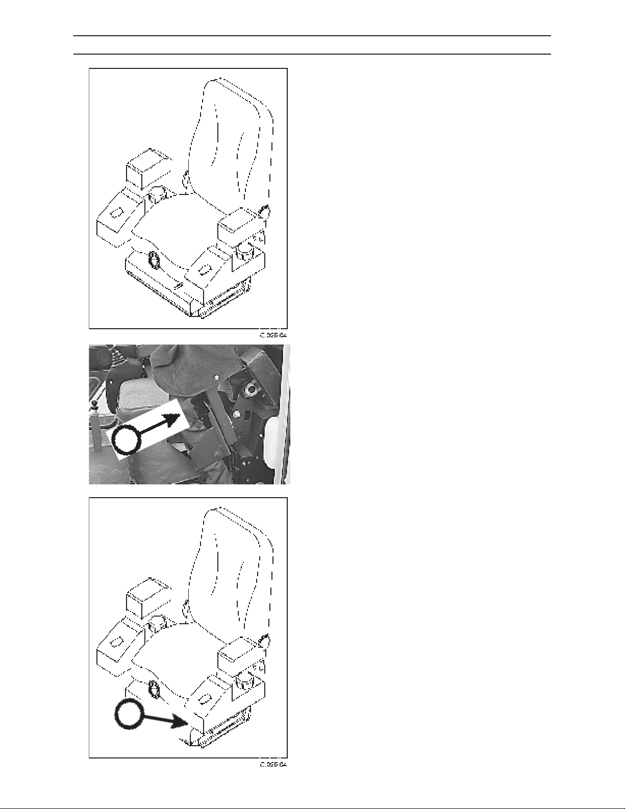
STABILIZER CONTROLS
Press top of switch to raise stabilizer. Press bottom of
switch to lower stabilizer.
B. Left stabilizer
C. Front/Rear stabilizer
D. Right Stabilizer
D
IMG.2423A
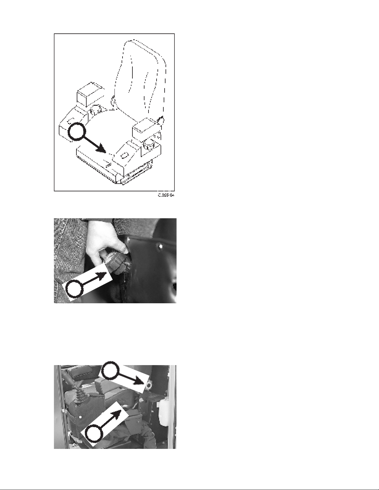
HOURMETER
The hourmeter shows hours of machine operation
in full hours and tenths hours. Use the hourmeter as
a guide for maintenance intervals throughout this
manual.
The hourmeter is located on the engine housing, behind the operator’s cab.
IMG.2364
2410 1111
415
Page 44
CONTROLS AND INSTRUMENTS
OPERATOR’S SEAT
Adjust operator’s seat using the following guidelines.
A
CONTROL CARRIER
The armrest and joystick (A) can be swung up and back
to allow easier access to the operator’s seat.
011.03
SEAT FRONT AND REAR POSITION
Lift lever (B) UP and hold.
Slide seat to desired position.
Release lever.
2410
B
416
1111
Page 45
A
CONTROLS AND INSTRUMENTS
OPERATOR’S SEAT, CONTINUED
SEAT HEIGHT
Firmly lift up and hold adjustment lever (A) until lever
releases.
While holding lever in the UP position, adjust seat to
desired height by adding or removing body weight to
the front or rear of seat cushion.
Firmly push DOWN on lever until seat locks (a click will
be heard).
B
C
SEAT SUSPENSION
While seated, rotate handwheel (B) until seat cushion
is level.
021.03
BACKREST
Rotate control knob (C) to select desired backrest position.
ARMREST
Rotate control knob (D) to select desired armrest
angle.
D
010.03
2410 1111
Pivot armrest up and parallel with backrest when not
in use.
417
Page 46
CONTROLS AND INSTRUMENTS
AM/FM STEREO CASSETTE RADIO
G.050.03
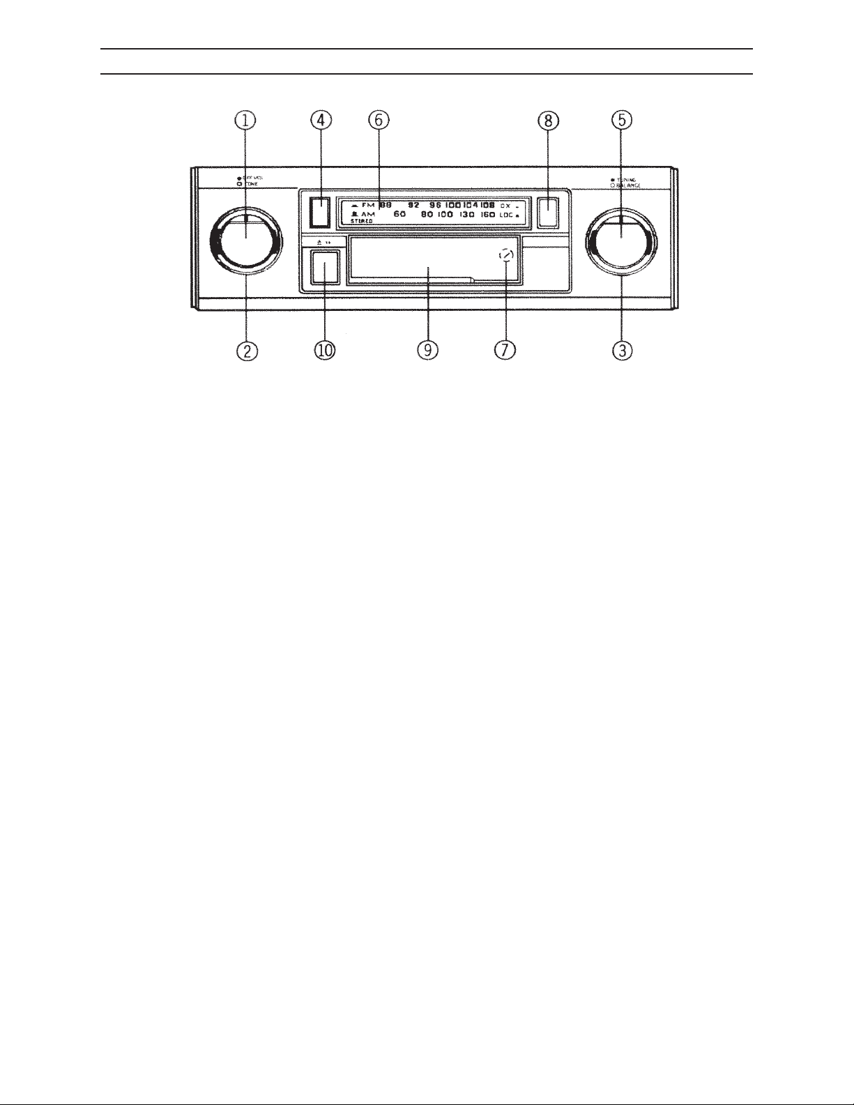
1. ONOFF SWITCH/VOLUME CONTROL
Rotate knob to the right to turn unit ON. Continue rotation until
desired volume level is obtained.
2. TONE CONTROL
Turn knob to right or left to adjust bass and treble levels.
3. BALANCE
Rotate knob left or right to obtain desired balance between left and
right speakers.
4. SELECTING A BAND
Press button to change radio band from AM to FM. FM broadcasts
will be received with the switch in the IN position, and AM broadcasts will be received with the switch in the OUT position.
5. MANUAL TUNING
Rotate knob left or right to select desired radio station. When tuning
in a station, always adjust the control so full signal is received. If
radio is o frequency, noise and reception problems will occur. The
dial pointer will move along the dial to indicate the frequency.
6. FM STEREO INDICATOR
Indicator will illuminate during reception of FM stereo broadcasts. If
indicator ickers or goes on and o as machine moves, stereo signal
may be too weak to reproduce clearly.
7. ANTENNA TRIMMER
It is important to adjust the antenna trimmer for optimum AM
reception. The antenna trimmer is located at the back of the tap slot.
Adjust following these instructions:
• Tune in a weak station around 1400 KHz on the AM band.
• Using a small screwdriver, slowly adjust trimmer for maximum
radio output.
8. FM LOCAL/DISTANT SELECTOR
This selector switch is incorporated to allow maximum reception in
both weak and strong FM signal areas. For normal reception conditions, and when receiving a wide range of signals including weak or
distant stations, switch should be set to the IN position, which will
allow maximum signal to the receiver. When in an extremely strong
(local) signal area, set switch to local setting (OUT position). This will
eliminate weak signals and suppress overly strong signals to avoid
overloading receiver input. When moving out of strong signal area,
return switch to the distant (IN) setting.
NOTE: The Local/Distant selector aects only FM signals.
9. CASSETTE DOOR
Hold cassette with exposed tap edge to the right and insert it into
the cassette door. Depress fully until cassette is engaged and begins
playing.
NOTE: Observe cassette operation cautions in the Care and Mainte-
nance section of the radio operation manual.
10. FAST FORWARD/EJECT BUTTON
This button performs two functions.
To eject a cassette, depress button fully, then release. Cassette will
eject and radio operation will resume.
To fast forward a tape, depress button halfway into the locked position. To stop fast forwarding, resume normal tape playback, depress
button slightly then release. Do not press fully in or the cassette will
be ejected.
NOTE: Never leave a cassette engaged in player when not in use. Doing so can cause damage to the cassette and/or mechanism of the
unit. Always press eject button and remove cassette when leaving a
vehicle.
2410
418
1111
Page 47
PRESTART INSPECTION
WARNING
NOTICE
WARNING
PRE-START INSPECTION
Do not use this machine until you read, study, and understand this manual to
learn how to properly operate this machine. Operating this machine without reading, studying, and understanding this manual could result in severe personal injury or death.
Failure to perform a daily inspection of the loader could result in machine damage
and severe personal injury.
PRESTART CHECKS: ON THE GROUND
Check for protective clothing (wear it) and safety equipment (know where it is).
Check entire machine by performing a thorough walk-around inspection.
Check for loose or missing parts. Tighten loose parts. Replace any missing parts.
Check for leaks in hydraulic hoses and/or lines (replace defective hoses and/or lines).
Check hydraulic hoses and lines for wear and/or damage. Replace any defective
hoses and/or lines.
Check that machine has been properly lubricated as spelled out in the Scheduled/
Periodic Maintenance Services section of this manual.
Check shields and guards. They must be in place and undamaged.
Check that safety decals are on machine and that they are readable.
Check that shut-o valves are open (if so equipped).
Check for dirt and grime on all hydraulic components. Clean away dirt and grime to
help prevent overheating.
Check for ice, snow, mud, oil, and grease on ladders and walkways. Clear away ice, snow, mud
oil, and grease to prevent slips and falls.
Check for any loose skid-resistant mats. Replace mats if they are loose.
Add hydraulic oil to reservoir if necessary.
Check for combustible or ammable materials. Remove them from machine if you nd them.
Check mounting hardware for tightness.
Check that machine will not be near electrical wires. See Operation section later in
this manual.
Check swing bearing for loose or missing fasteners. Tighten loose fasteners. Replace
missing fasteners per maintenance instructions.
Check booms for damage, cracks, debris, mounting pin retention, and other problems.
Immediately report any structural problems (cracks) to an authorized dealer for diagnosis and
repair or replacement.
machine, and le the copy as a record of inspection as required per OSHA or local governing body.
2410 5-1 1111
Check that truck/trailer is on rm level, ground and that the parking brake is set.
Check that upper frame and engine area are free of leaves, twigs, branches and other debris.
Check electrical system for worn insulation or frayed wires and loose connections.
You can copy the pages in this section. Check o each inspection item before operating the
Page 48
PRESTART INSPECTION
WARNING
NOTICE
PRESTART CHECKS: ON PLATFORM
HAND HOLDS AND STEPS
severe personal injury or death.
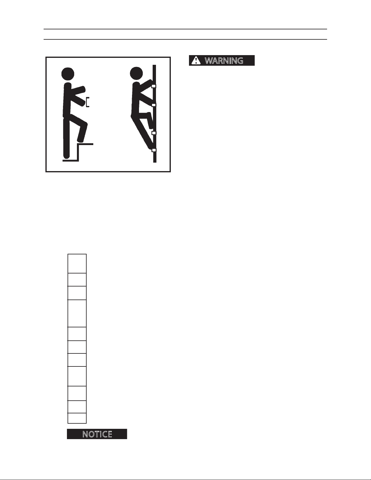
Use provided hand holds and steps while maintaining at least 3 points of support (1 foot and 2 hands
or 2 feet and 1 hand) when getting on and o machine. Face machine when getting on and o of it.
Never use controls as hand holds. Never use steering wheel as a hand hold. Moving the steering
wheel from its center position will COMPLETELY
turn machine right or left.
DO NOT mount machine if hand rails or steps are
broken or missing. Get them repaired rst.
DO NOT jump on or o machine unless it has
touched a live electrical wire and it must be exited.
Ensure rm foot position when getting on and o
machine. Be careful of slippery conditions on platform, steps, and hand holds when getting on and
o machine.
Slips and falls can cause
Remove oil, grease, mud, ice, etc. before mounting
or dismounting machine.
To prevent slips and falls, replace skid-resistant material if it is worn, damaged or missing.
Check hydraulic hoses in platform/boom end area for
defective hoses and/or lines.
Check safety decals. They must be present and readable.
Check control levers/pedals for free movement.
Check booms for damage, cracks, debris, mounting pin retention, and other problems.
Immediately report any structural problems (cracks) to an authorized dealer for diagnosis
and repair or replacement.
Check fuel tank (ll tank at end of shift to reduce water condensation).
Check hydraulic reservoir uid level.
Check engine oil level. Add engine oil if necessary.
Check radiator coolant level and make sure radiator ns are clean. Add proper coolant
mixture if necessary. Clean radiator of all debris.
Add hydraulic oil to reservoir if necessary.
wear and/or damage. Replace any
2410 5-2 1111
Check that all cab windows are clean and clear. Replace any damaged polycarbonate
window material.
Check for mud and debris on cab oor (clean away mud and debris).
Check air cleaner. Clean or replace air lter if necessary.
You can copy the pages in this section. Check o each inspection item before operating
the machine, and le the copy as a record of inspection as required per OSHA or local governing body.
Page 49
PRESTART INSPECTION
NOTICE
WARNING
PRESTART CHECKS: IN THE CAB
HAND HOLDS AND STEPS
severe personal injury or death.
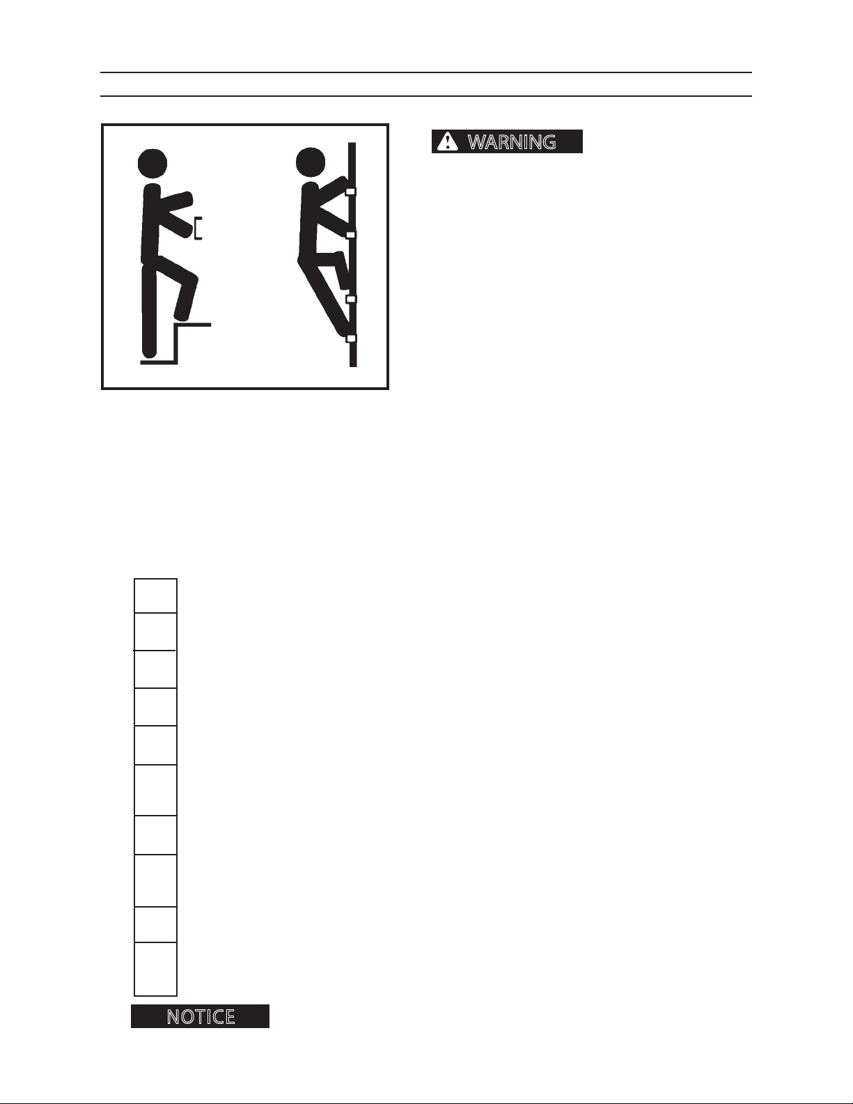
Use provided hand holds and steps while maintaining at least 3 points of support (1 foot and 2 hands
or 2 feet and 1 hand) when getting on and o machine. Face machine when getting on and o of it.
Never use controls as hand holds. Never use steering wheel as a hand hold. Moving the steering
wheel from its center position will COMPLETELY
turn machine right or left.
DO NOT mount machine if hand rails or steps are
broken or missing. Get them repaired rst.
DO NOT jump on or o machine unless it has
touched a live electrical wire and it must be exited.
Ensure rm foot position when getting on and o
machine. Be careful of slippery conditions on platform, steps, and hand holds when getting on and
o machine.
Slips and falls can cause
Remove oil, grease, mud, ice, etc. before mounting
or dismounting machine.
To prevent slips and falls, replace skid-resistant
material if it is worn, damaged or missing.
Check that there is no mud or debris on cab oor (clean away mud and debris).
Check for free movement of controls.
Check and review safety decals, that all are present and can be clearly read.
Check that all cab window material is clean and clear. Replace any damaged polycarbonate
window material.
Check that re extinguisher is adequately charged.
Check instrument panel for broken gauges and/or broken indicator lights. Have
gauges and/or indicator lights repaired if necessary.
Check fuel gauge to be sure machine has enough fuel. Refuel machine if necessary.
Check window emergency exits.
2410 5-3 1111
Check cab operator protection structure for damage. Have structure repaired if necessary.
Check that all items in cab that are not part of the machine, such as lunch boxes or
tools, are secured.
You can copy the pages in this section. Check o each inspection item before operating the
machine, and le the copy as a record of inspection as required per OSHA or local governing body.
Page 50
PRESTART INSPECTION
NOTICE
FIRE PREVENTION
Fires can cause personal
injury or machine damage.
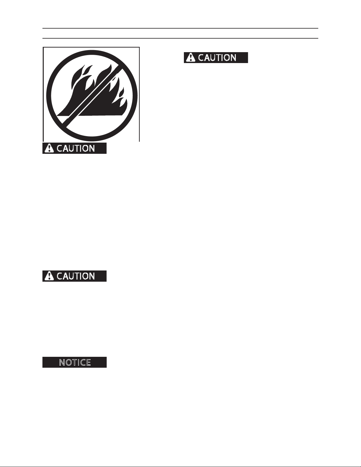
Keep machine clean. Remove debris, especially from
heat sources. Fire prevention beats re ghting. Hourly
or daily inspections can reduce the possibility of res.
Forest debris can collect on the machine and cause a re. When forest debris mixes
with ammable uids in a hot, conned space, the risk of a re starting greatly increases. KEEP THE MACHINE
CLEAN.
Check machine daily for re hazards. Remove debris from areas of the machine that create heat and that are
potential re start points. Depending on machine model, check for ammable debris in the following locations:
• Engine block • Turbocharger • Electrical connections
• Exhaust manifold • Battery • Control valves
Fire needs fuel. Remove combustible material (fuel for re) from heat sources. Keep the machine clean. Remove
the following materials, and other combustible materials from areas of the machine that create heat:
• Pine needles • Twigs • Debris
• Shop rags • Oil spills • Coolant mixture
• Leaves • Sticks • Sawdust
• Grease • Bark • Diesel fuel
Keep the machine clean. Risk of re increases if combustible materials and ammable materials build up on machine. This machine is not designed to house or store combustible materials.
Regularly remove ammable materials (such as diesel fuel, engine oil, hydraulic oil, and grease) from all areas of
the machine. Clean up after working. Keep the fuel and hydraulic systems in good repair.
Check hydraulic hoses, fuel lines, and ttings for leaks. Tighten loose ttings. If hoses or lines are bent, kinked, or
show signs of wear, install new parts. Check electrical connections to be sure they are clean and secure.
Frayed, damaged or worn insulation on battery cables or other wires may lead to electrical res. Check cables
and wires and replace if insulation is frayed, worn, or damaged.
At the end of each shift ALWAYS stay with the machine for 30 minutes after shutting down
the engine to ensure there is no forest debris/trash re start up. Keep a re extinguisher ready during this 30 minute
cool down.
2410 5-4 1111
Page 51
OPERATION
OPERATION
GENERAL GUIDELINES
Only a trained, qualied, and authorized operator shall be allowed to operate
this machine. Only use this machine after carefully reading this manual and learning how to safely operate and maintain this machine. Unsafe operation can cause severe personal injury or death.
OPERATOR PREPARATION
Operator must be fully trained, qualied, and
authorized to operate this machine.
Before running this machine, operator must know the
location and purpose of
• controls
• indicator lights
• instruments
• local operating safety rules and procedures
• safety and instruction decals (see Safety Decals
Section)
Operators must be at least 18 years old to operate this machine (Code of Federal Regulations: Labor).
Never operate this machine while under the inuence of drugs or alcohol. Use of prescription or over-thecounter drugs or medications requires advice from a medical practitioner on whether or not machine can be
safely operated.
Operators may not run this machine if subject to dizziness, seizures, or motion disturbance.
Do not operate this machine unless it is properly mounted to a truck or trailer for stability.
Never operate this machine with stabilizers in raised position.
No riders are allowed on this machine. Machine riders can fall from machine or be injured by movement of
machinery, causing severe personal injury or death. Do not allow riders on a machine that is operating or
moving.
FOLLOW ALL SAFETY OPERATING INSTRUCTIONS AND PRACTICES. SEE GENERAL SAFETY SECTION.
Keep machine away from power lines.
If this manual is lost, contact an authorized dealer for a new manual. Keep manual in the manual storage pouch
in the cab.
Report any noticeable machine problems to people who can repair the problems before machine is used.
Be sure cab windows are clean before operating machine. Cab windows must be clear of ice and frost. Replace
windows that are cracked, yellow, and/or hazy.
Remember, operators are key to the safe operation of this machine.
2410
61
1111
Page 52
OPERATION
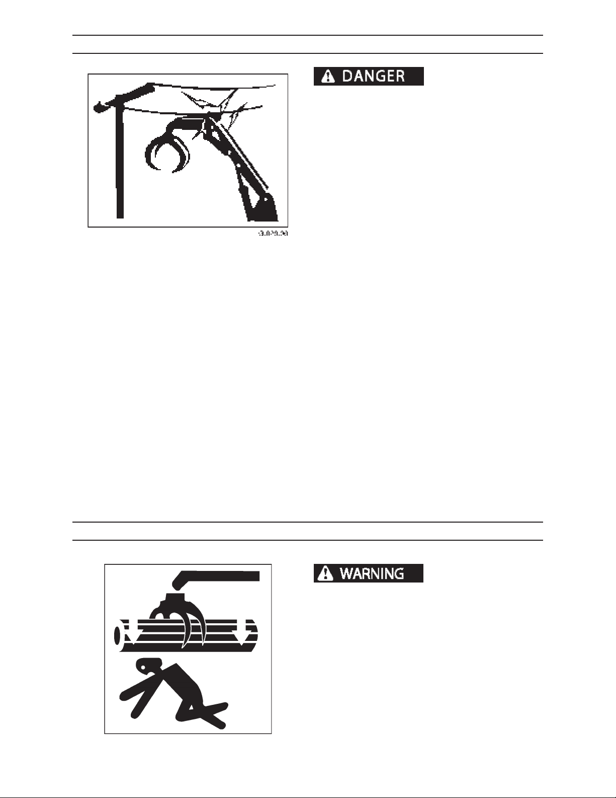
ELECTROCUTION DANGER
LINES WITH BOOM, LINE, OR LOAD WILL CAUSE
SEVERE INJURY OR DEATH. WATCH FOR OVER
HEAD POWER LINES. TREAT ANY LINE AS LIVE
AND DANGEROUS. IF AT ALL POSSIBLE, HAVE THE
POWER LINE DISCONNECTED BEFORE STARTING
WORK.
Never move any part of machine or load closer than
10 feet plus twice the line insulator length to electric
lines. A line insulator is what connects an electric line
to an electric pole.
For example, if a line insulator is 6 inches long, stay at
least 10 feet plus twice the line insulator length (2x6
=12 inches or 1 foot) from electric line, which means
machine must stay at least 11 feet from this electric
line.
If machine touches an electric line, stay inside the cab.
Carefully move machine or load away from electric
line, without pulling the line down.
CONTACTING ELECTRIC
DO NOT allow anyone else to touch machine while
it is touching an electric line. If machine cannot be
moved away from the electric line without pulling line
down, have someone contact the utility company to
disconnect power from line. If this is not possible, or
if machine begins to burn, jump away from machine
to the ground with both feet together, in one smooth
jump. DO NOT touch machine and ground at the same
time or else electricity in the line will go through the
body. Get away from machine after jumping.
Notify utility company immediately. DO NOT let anyone near machine while it is touching an electric line.
OVERHEAD LOADS
booms can cause severe injury or death.
The loader operator is responsible for ensuring that
booms or loads are never suspended over or near
personnel.
Falling or swinging logs or
2410
G.027.03
• Always know where other people are working at
the job site in relation to the loader.
• Maintain good communication with everyone on
the job.
• Stop operations if someone on the ground approaches the machine.
62
1111
Page 53
OPERATION
GETTING ON MACHINE
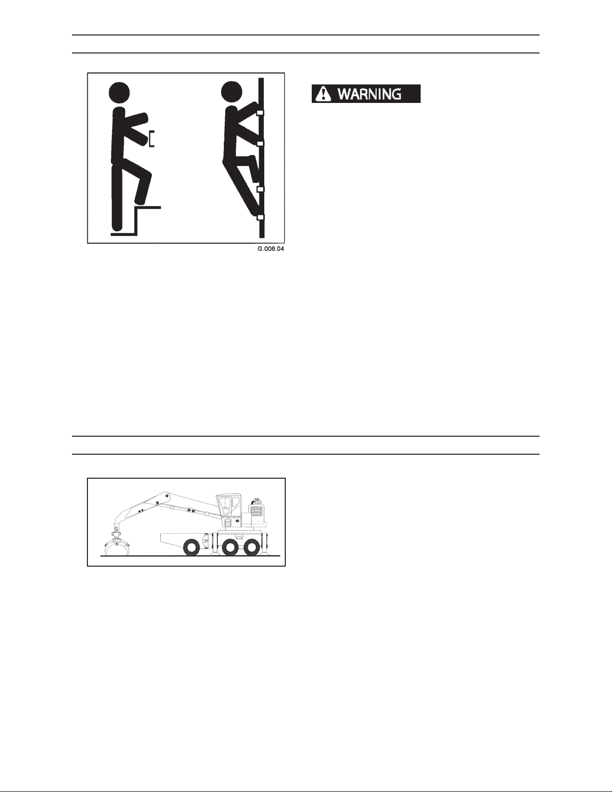
HAND HOLDS AND STEPS
severe personal injury or death.
Use provided hand holds and steps while maintaining at least 3 points of support (1 foot and 2 hands
or 2 feet and 1 hand) when getting on and o machine. Face machine when getting on and o of it.
Never use controls as hand holds. Never use steering wheel as a hand hold. Moving the steering
wheel from its center position will COMPLETELY
turn machine right or left.
DO NOT mount machine if hand rails or steps are
broken or missing. Get them repaired rst.
DO NOT jump on or o machine unless it has
touched a live electrical wire and it must be exited.
Ensure rm foot position when getting on and o
machine. Be careful of slippery conditions on platform, steps, and hand holds when getting on and
o machine.
Slips and falls can cause
Remove oil, grease, mud, ice, etc. before mounting
or dismounting machine.
To prevent slips and falls, replace skid-resistant material if it is worn, damaged or missing
MACHINE START UP
1. Perform a pre-start inspection (refer to
Pre-Start Inspection Section.)
2. Before start up, walk completely around machine
and make sure no obstacles or personnel are in
the area.
3. Sound horn before operation.
G.048.03
4. Check all controls for proper function and response before starting work (refer to
Controls and Instruments Section).
5. Maintain adequate distance between machine
and other equipment and personnel.
2410
63
1111
Page 54
OPERATION
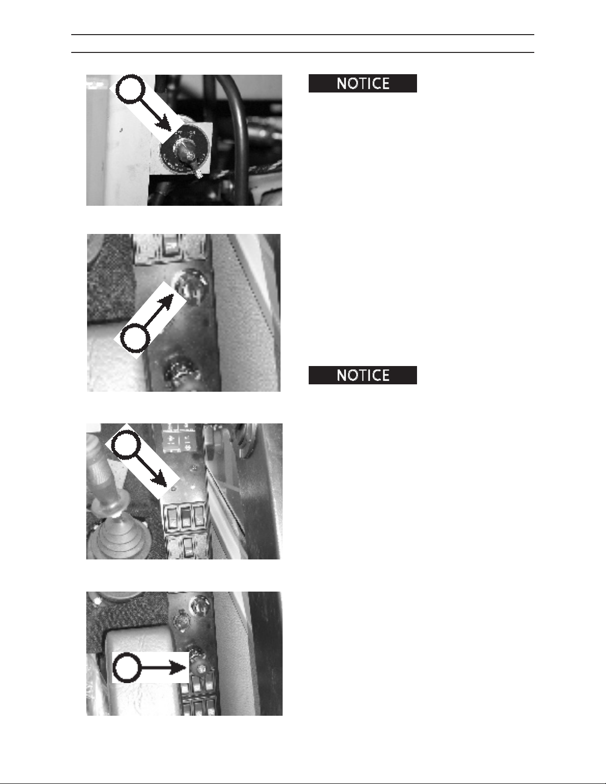
STARTING THE ENGINE
A
B
IMG.2385
Pressing starter button while
engine is running can damage starter.
1. Make sure battery disconnect master switch (A) is
ON.
1. Insert key in ignition switch (B).
2. Turn key to the right (ON position). Verify that
the error code indicator light (C) is not lit. If the
error code indicator light is lit, see Cold Weather
Starting Procedure later in this section. If the waitto-start indicator is not lit, turn key all the way to
the right and hold until engine starts. Release key
when engine starts. If engine fails to start after 30
seconds, allow starter to cool a few minutes. Try
starting engine again. If engine still will not start,
see engine operator’s manual and Starting with a
Booster Battery later in this section.
4. Turn throttle knob (D) clockwise about 1/3 turn to
increase engine speed.
5. Run engine at partial-throttle and no load for
approximately ve minutes to allow machine to
warm up.
C
If ambient (outside) air temperature is below 32°F (0°C), and starter aid is necessary,
refer to the engine operator’s manual.
2410
D
64
1111
Page 55
OPERATION
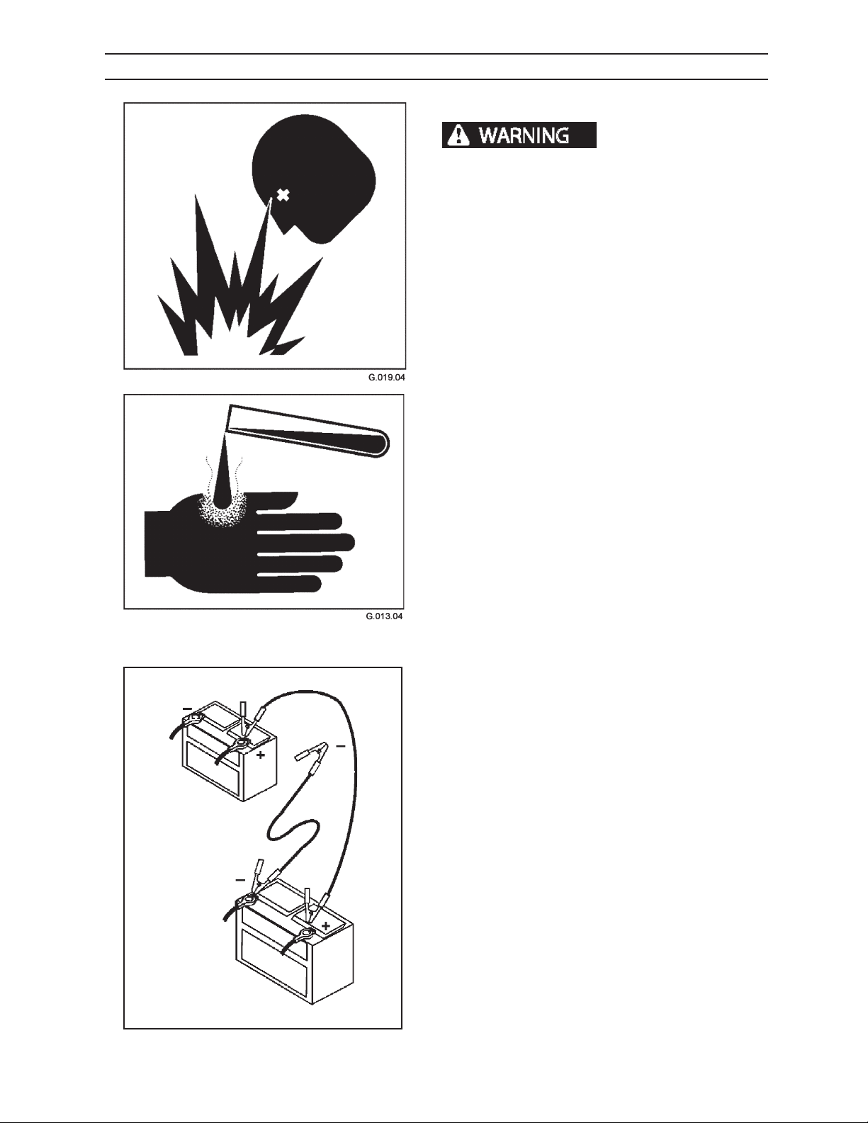
STARTING MACHINE WITH A BOOSTER BATTERY
BATTERY SAFETY
Batteries produce explo-
sive gases.
Keep sparks, ames, and cigarettes away from batteries. Ventilate properly when charging or using batteries
in enclosed space. Always shield eyes with goggles and
wear a face shield when working near batteries. Do not
lean over batteries during this operation. Always connect
positive (+) to positive (+) and negative (-) to negative
(-). For further instructions, see Jump Starting Battery in
Operation Section. If battery acid contacts eyes, ush
them with water for 15 minutes and seek immediate
medical attention.
Battery acid is poisonous and can cause severe burns. If
acid is taken internally, call a physician immediately. If
acid contacts skin or clothing, ush with water immediately. Keep batteries away from children.
Battery posts, terminals, and related accessories contain
lead and lead components, chemicals known to the State
of California to cause cancer and reproductive harm.
Wash hands after handling.
Never charge a battery or jump start engine if battery is
frozen. Warm battery to 60°F (16°C) or it may explode.
Be sure vent caps are tight. When jump starting from
another machine, be sure machines do not touch. This
machine has a 12-volt starting system. Use equal voltage
for jump starting.
2410
Machine
Battery
A
C
Booster
Battery
D
B
G.060.02
JUMP STARTING PROCEDURE
1. Turn battery disconnect master switch OFF. Re-
move key from ignition switch.
2. Clamp one end of rst booster cable to positive
terminal of discharged battery (A) (terminal connected to starter or solenoid).
3. Clamp other end of rst booster cable to positive
terminal of booster battery (B).
4. Clamp one end of second booster cable to nega-
tive terminal of booster battery (C).
5. Clamp other end of second booster cable to en-
gine block or frame of machine (D) (to keep sparks
away from either battery).
6. Insert key in ignition switch. Turn battery discon-
nect master switch ON.
7. After starting engine, remove booster cables
in reverse order from how they were put on. To
prevent sparks, keep booster cable clamps from
touching.
65
1111
Page 56
A
OPERATION
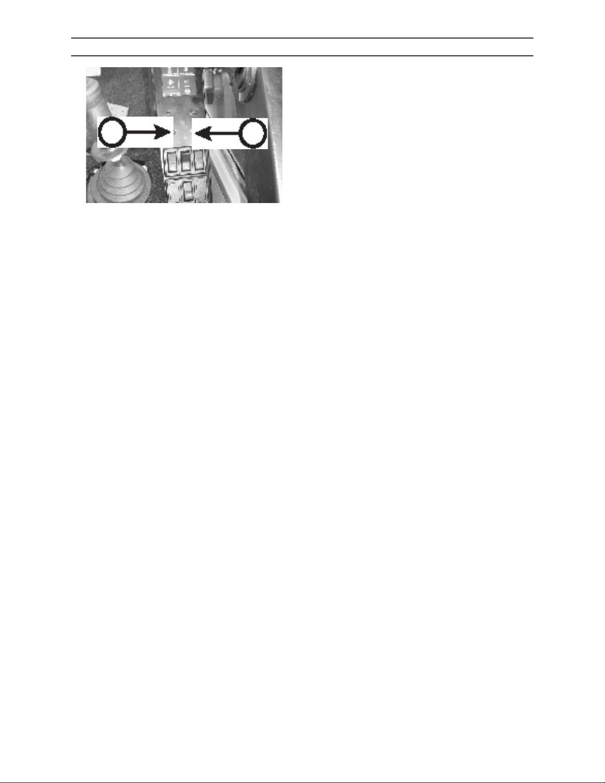
INDICATOR LAMP CHECKS
Following are the sequences of indicator lamp error
codes:
WHEN STARTING ENGINE
Red error code indicator (A) and yellow error code
B
indicator (B) will both illuminate for 2 seconds at start
up.
STARTING ENGINE WITH COLD START AID OPERA
TION
Red error code indicator (A) and yellow error code
indicator (B) will both illuminate until operation is
complete at start up.
ERROR DETECTED AT START UP E.G. LACK OF
LUBRICATION OIL PRESSURE AFTER START DELAY
EXCEEDED
Red error code indicator (A) will remain illuminated
after the 2 second delay.
2410
66
1111
Page 57
OPERATION
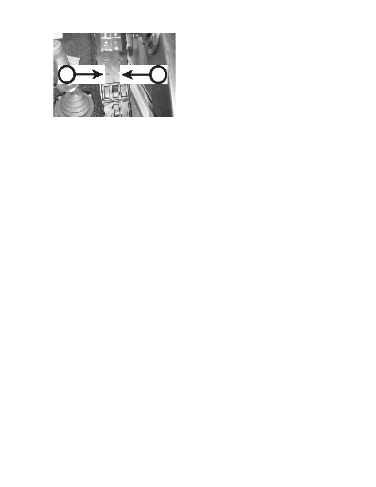
INDICATOR LAMP CHECKS, CONTINUED
WHEN STARTING ENGINE
Following are the sequences of error code indicator
error codes:
IF ENGINE FAILS TO START
A
B
NO DETECTED FAULTS
Red error code indicator (A) and yellow error code
indicator (B) will both not be illuminated.
ELECTRICAL FAULT WARNING
The yellow error code indicator (B) will be illuminated.
STOP ENGINE
Red error code indicator (A) will ash. Fault has been
detected that prevented start of engine.
AFTER STARTING ENGINE
NO DETECTED FAULTS
Red error code indicator (A) and yellow error code
indicator (B) will both not be illuminated.
OIL PRESSURE LOW
The red error code indicator will be illuminated.
COOLANT/AIR INTAKE TEMPERATURE HIGH
Yellow error code indicator (B) will ash.
STOP ENGINE FAULT/DERATE CONDITIONS
The red error code indicator (A) will be ashing.
ELECTRICAL FAULT WARNING
Yellow error code indicator (B) will be illuminated.
OIL PRESSURE LOW AND ELECTRICAL FAULT
Red error code indicator (A) and yellow error code
indicator (B) will both be illuminated after start up.
STOP ENGINE FAULT/DERATE CONDITIONS AND
ELECTRICAL FAULT
The red error code indicator (A) will be ashing and
yellow error code indicator (B) will be illuminated.
OIL PRESSURE LOW AND COOLANT/AIR INTAKE
TEMPERATURE HIGH
The red error code indicator (A) will be illuminated and
yellow error code indicator (B) will be ashing.
2410
67
1111
Page 58
OPERATION
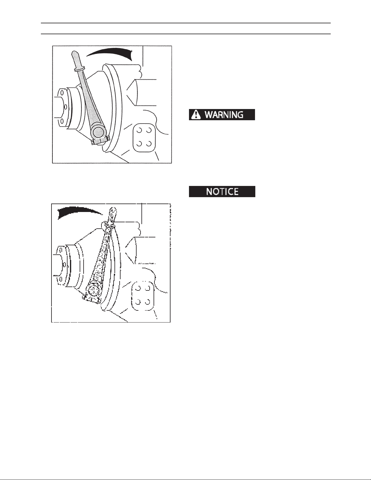
COLD WEATHER STARTING ENGINE/PUMP DISCONNECT OPTIONAL
1. Locate clutch disconnect lever (outside rear of cab
between rear of cab and hydraulic oil reservoir).
2. Push lever away (A) from engine to disconnect
hydraulic pumps.
3. Start engine (see procedures on Page 6-4).
4. Allow engine to warm up for approximately ten
minutes.
DO NOT engage pumps
with engine running. Engaging pumps with engine
running may cause machine to move unexpectedly,
which may lead to serious personal injury or death.
5. Shut engine down.
-A-
G.052.03
Side panel and top panel removed
from illustration for clarity.
-B-
G.053.03
6. Engage pumps by slowly pulling the dicsonnect
lever toward (B) the engine.
7. Start engine.
These instructions apply
to optional controls and instruments available from an
authorized dealer.
2410
68
1111
Page 59
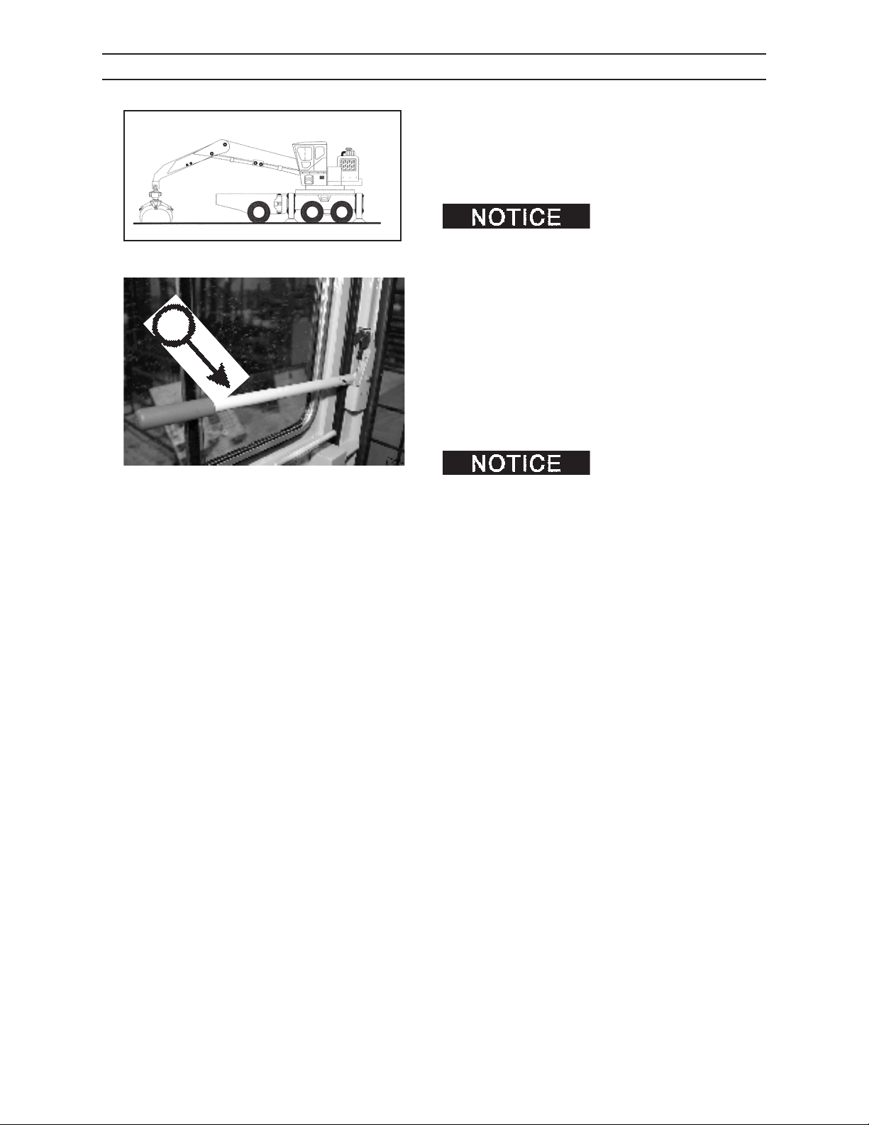
A
OPERATION
WARM UP PERIOD
1. Be sure area is clear of personnel.
2. Close cab door.
3. Pull down control shut o lever (A) to engage
control system.
G.048.03
hydraulic system to reach operating temperature
before beginning operation. Cold and thick oil cannot ow fast enough to the pump to meet output
demand. Cavitation and extreme damage may be
caused by operating the machine when the hydraulic
oil is too cold to ow easily.
4. Warm up the hydraulic system by
• engaging and disengaging controls to help speed
warm up of hydraulic components, and;
• cycling all controls to allow warm oil to circulate
through all cylinders and lines.
It is important to allow the
IMG.2577
Do not idle engine for excessively long periods. Long periods of idling (more
than 10 minutes) can damage an engine because
combustion chamber temperatures drop so low the
fuel will not burn completely.
2410
69
1111
Page 60
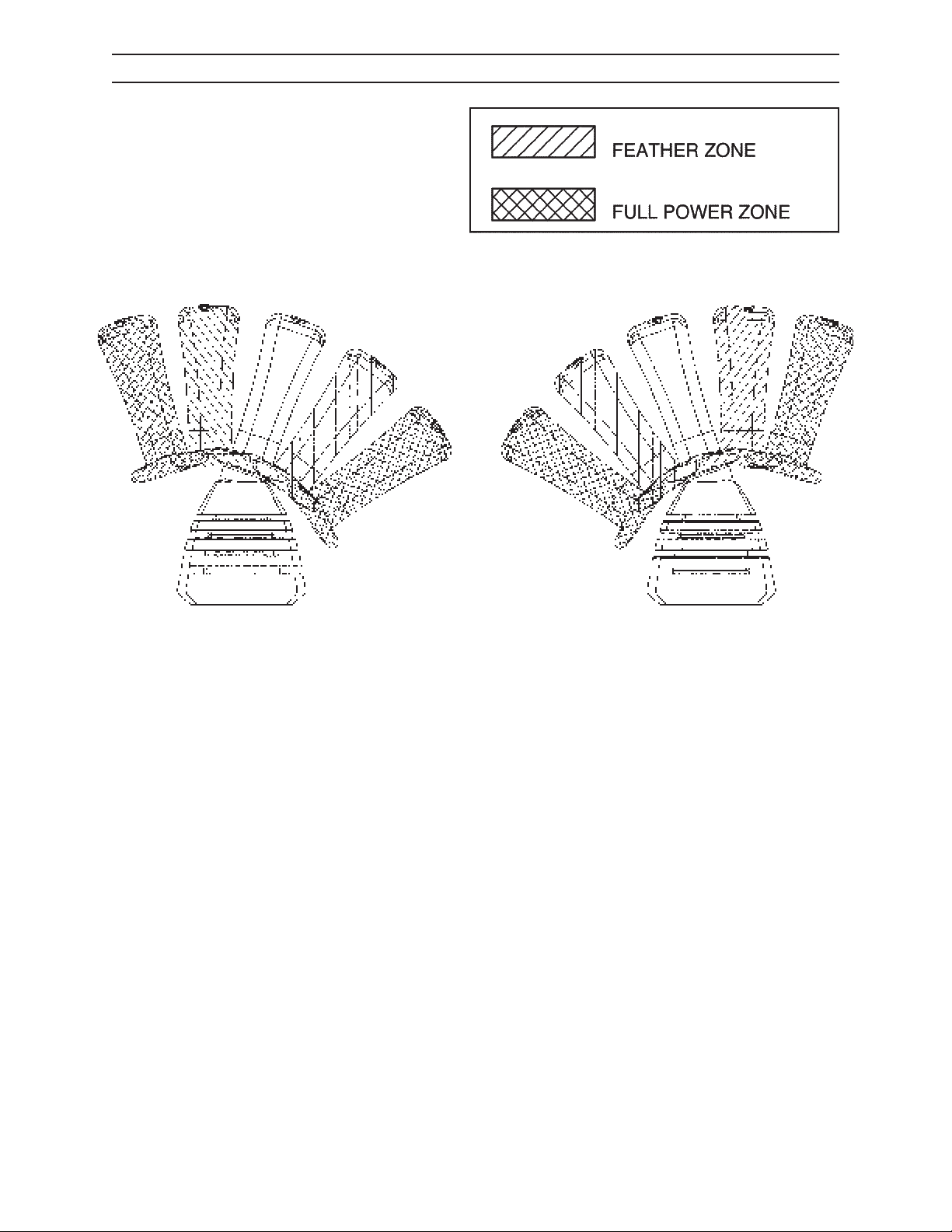
OPERATION
FEATHERING THE CONTROLS
G.031.03
G.030.03
Rough operation can be dangerous, hard on the machine, and hard on the operator.
DO NOT jerk control levers to full speed, or from one direction to another.
Feather controls this way:
1. Move joystick control gently from neutral to start motion.
2. After a slow, smooth start, move joystick control to desired speed position.
3. Just before stopping movement, move joystick control gently back to neutral.
This method of carefully manipulating the controls is called feathering. Work can done more eciently by feathering controls than by jerking controls.
There is a rhythm to operating this machine. Feathering the controls will help the operator nd and take advantage of this rhythm.
2410
610
1111
Page 61
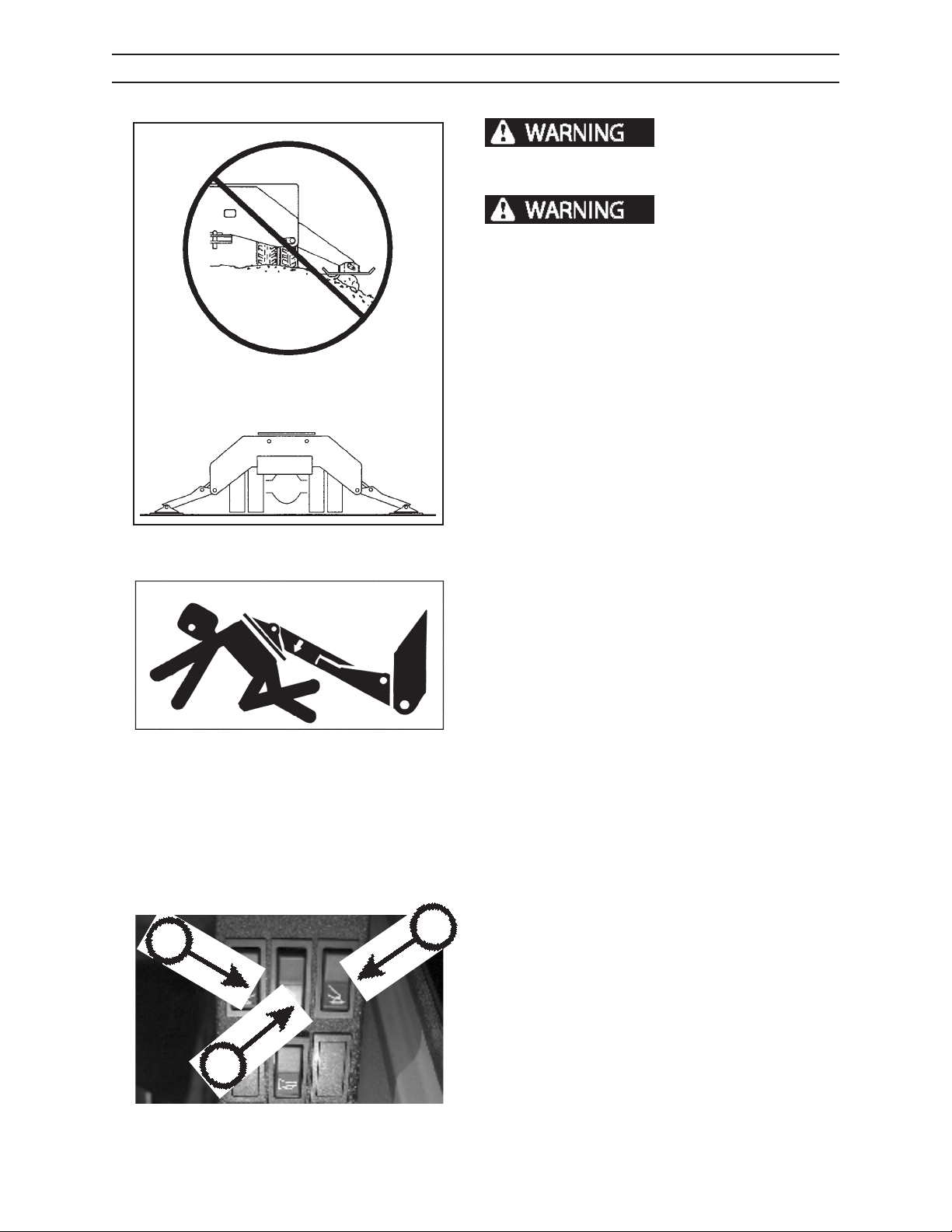
OPERATION
USING STABILIZERS
cause severe personal injury or machine damage.
Lower all stabilizers before operating machine.
stabilizers can cause serious personal injury or
death. Clear all personnel from work area before
lowering stabilizers.
It is the responsibility of the operator to make sure all
personnel are clear of the stabilizers before lowering
them. When setting the stabilizers, make sure they are
sitting on rm, solid ground.
DO NOT set stabilizers on rocks, stumps, curbs, edge of
paving, etc. or on soft or unstable ground.
1. Position loader on rm, level ground with stabilizers down to ensure stability while operating.
2. Double check to ensure no persons are close to
truck and/or loader.
Unstable platform can
Coming into contact with
A
G.132.03
G.043.03
C
3. Clear ice and snow from the area where the
stabilizer pads will be lowered. Do not operate or
position loader on slippery surfaces.
4. Lower stabilizer legs to raise truck or trailer tires
about 1-1/2 to 2 inches o the ground. The entire
loader should rest rmly on the stabilizer pads.
5. Follow these stabilizer operating guidelines:
• Never allow another person to be on the
loader or in and around the truck when lowering or raising stabilizers.
• Lift boom from transport position and make
a test lift to check ground conditions under
stabilizers.
• Never operate machine with stabilizers in
raised position.
STABILIZER CONTROL SWITCHES
Left Stabilizer (A)
Top Position: Raise stabilizer
Bottom Position: Lower stabilizer
2410
B
IMG.2423A
Front/Rear Stabilizer (B)
Top Position: Rear stabilizer
Bottom Position: Front stabilizer
Right Stabilizer (C)
Top Position: Raise stabilizer
Bottom Position: Lower stabilizer
611
1111
Page 62
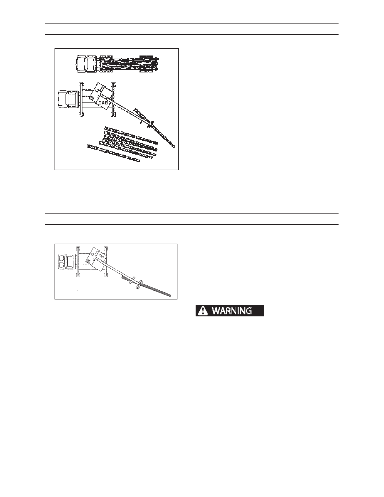
OPERATION
LANDING LAYOUT
• The loader operator is in one of the best positions
on the work site to notice a problem and warn
others by sounding the horn. The loader operator is responsible for the safety of people on the
ground.
• All landings (decks) should provide an area clear
of suspended loads for landing personnel (deck
hands) to work. Remember, logs can roll or be
thrown a considerable distance.
• If clearance of suspended loads cannot be provided, STOP loading operations and lower grapple
while deck hands are working on the landing.
• All obstructing trees should be removed to ensure
clearance for loading.
G.034.03
• Never locate landing near overhead electrical
lines. See Electrocution Dangers in this section for
instructions.
HEELING PICKING UP LOGS OR POLES
• Never operate this machine with tires touching
the ground. Lower stabilizers to the ground, and
raise tires slightly o the ground.
• Always lift and heel long logs from butt end of log
(larger end). Place grapple on log as illustrated so
the log will not hit the stick boom cylinder.
• Never pinch a log. Always make sure the grapple
G.046.03
wraps around the log.
Always place logs in heel
on opposite side of boom, away from cab. This can
reduce the risk of a log ying toward the cab if a
log slips in the grapple.
• Never heel logs from the center — this puts the
ends of the logs too close to the boom cylinders
and the cab when drag loading.
2410
• Never swing load or grapple over truck cab being
loaded.
• Make sure truck driver and other personnel are
away from truck and loader when operating
loader.
• On booms without heels, pick up logs toward the
butt end. When lifting logs at their balance point,
take care when rotating logs to make sure they
clear the loader and other obstructions.
612
1111
Page 63
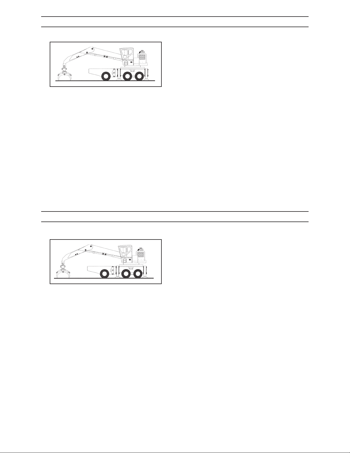
OPERATION
GRAPPLE CONTROL
Study and learn the grapple control functions (see
Controls and Instruments Section). Improper rotation
of grapple or accidental opening of grapple will cause
loss of control of the load.
• Do not change function arrangement.
• Use proper grapple to match application.
G.048.03
• For log handling always use a log bypass, or com-
bination bypass/pulp grapple.
• For short wood handling, use a log bypass, combi-
nation bypass or butt-style pulpwood grapple.
• Never swing and load a single log or branch by
pinching the sides of the log or stem with the
grapple jaw tips. Always clamp the log or branch
within the grapple jaws.
STOPPING THE MACHINE
1. Bring machine to a complete stop.
2. Lower attachment to ground with the main and
stick booms fully extended. The grapple should
be open with the jaw tips on the ground. For
extra stability on unfrozen ground, jaw tips can be
closed slightly so that they dig into the ground.
G.048.03
3. Slow engine to LOW IDLE. Run engine at low idle
for at least 2 minutes to cool engine.
4. Turn key switch to OFF to stop the engine.
5. Remove key from ignition switch.
2410
613
1111
Page 64
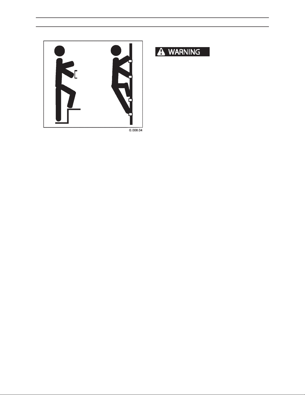
OPERATION
GETTING OFF MACHINE
HAND HOLDS AND STEPS
severe personal injury or death.
Use provided hand holds and steps while maintaining at least 3 points of support (1 foot and 2 hands
or 2 feet and 1 hand) when getting on and o machine. Face machine when getting on and o of it.
Never use controls as hand holds. Never use steering wheel as a hand hold. Moving the steering
wheel from its center position will COMPLETELY
turn machine right or left.
DO NOT mount machine if hand rails or steps are
broken or missing. Get them repaired rst.
DO NOT jump on or o machine unless it has
touched a live electrical wire and it must be exited.
Ensure rm foot position when getting on and o
machine. Be careful of slippery conditions on platform, steps, and hand holds when getting on and
o machine.
Slips and falls can cause
Remove oil, grease, mud, ice, etc. before mounting
or dismounting machine.
To prevent slips and falls, replace skid-resistant material if it is worn, damaged or missing
2410
614
1111
Page 65
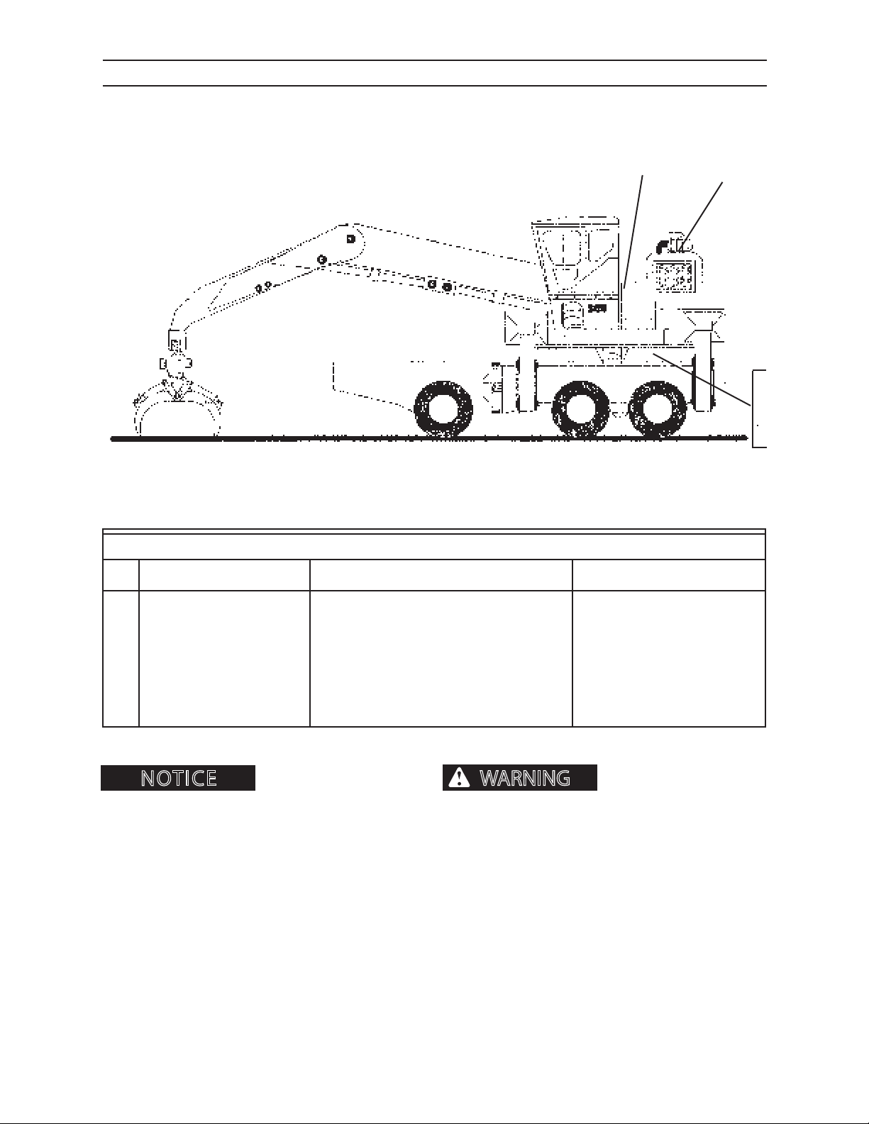
BREAKIN PERIOD
WARNING
NOTICE
BREAKIN PERIOD
LOADER
AFTER FIRST 10 HOURS OF OPERATION
2
1
3
4
5
G.055.03
KEY COMPONENT SERVICE SPECIFICATION
1. Hydraulic Reservoir Check uid level - 65 gallons (246 L) Full mark. Use
Premium A.S. Hydraulic Fluid
2. Fuel Tank Check fuel level - 89 gallons (337 L) Full mark
3. Loader (not shown) Visually check for any loose hardware
or uid leaks.
4. Outer Swing Bearing Fasteners Check Tighten to 600 ft-lbs (814 N•m)
5. Inner Swing Bearing Fasteners Check Tighten to 600 ft-lbs (814 N•m)
The above uid capacities are
approximate values. Be sure to check levels after lling.
DO NOT OVERFILL.
DURING THE FIRST 100 HOURS OF OPERATION
1. Use seasonal viscosity grade oil as specied in Fuels and Lubricants Section.
2. Avoid excessive engine idling.
3. Check all accessible hardware for tightness.
ner capscrews on the swing bearing can cause the
upper and lower frame to separate, causing severe
injury or death. Read and follow all torque instructions in this manual.
Loose outer bolts or in-
4. Check engine oil level regularly.
5. Check hydraulic uid regularly.
2410
71
1111
Page 66
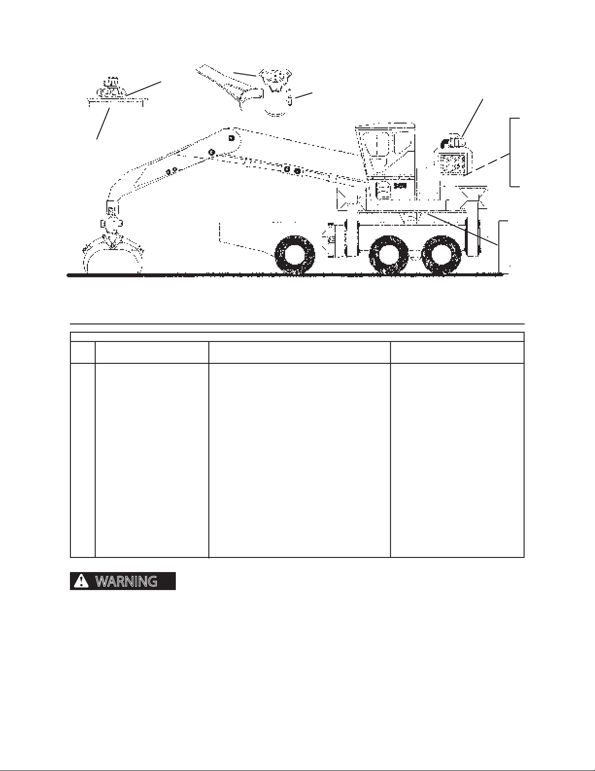
BREAKIN PERIOD
WARNING
6
10
11
3
1
5
2
4
12
7
8
9
G.055.03
AFTER FIRST 100 HOURS OF OPERATION
KEY COMPONENT SERVICE SPECIFICATION
1. Engine Oil and Filter Drain and Replace See Fuels and
Lubricants section
2. Case Drain Filter Replace Use Genuine parts
3. Hydraulic Reservoir Replace Use Genuine parts
Return Line Filter
4. Fuel Filters Replace Use Cat parts
5. Pinion Gear Fastener Check tightness, torque if necessary 420 ft-lbs (569 N•m)
6. Swing Drive Fasteners Check tightness, torque if necessary 437-483 ft-lbs (593-655 N•m)
7. Outer Swing Bearing Check tightness, torque if necessary 600 ft-lbs (814 N•m)
Fasteners
8. Inner Swing Bearing Check tightness, torque if necessary 600 ft-lbs (814 N•m)
Fasteners
9. Heel Fasteners (opt) Check tightness, torque if necessary 162-178 ft-lbs (220-241 N•m)
10. Swivel Torque Arm Fast. Check tightness, torque if necessary 76 - 84 ft-lbs. (103-114 N•m)
11. Swivel Fasteners Check tightness, torque if necessary 266-294 ft-lbs. (360-399 N•m)
12. Engine Refer to engine operator’s manual
TO TIGHTEN A LOOSE BOLT OR CAPSCREW
Loose outer bolts or in-
ner capscrews on the swing bearing can cause the
upper and lower frame to separate, causing severe
injury or death. Read and follow all torque instructions in this manual.
1. Torque the bolt or capscrew to recommended ftlbs. Recheck every 10 hours until torque stabilizes.
2. Check the two adjacent bolts (on either side of
loose bolt) for proper torque and recheck every 10
hours until torque stabilizes.
2410
3. If any of these bolts or capscrews do not take
the torque, or come loose again, they must be
replaced, including adjacent bolts/capscrews.
Replace with factory-approved parts.
72
0209
1111
Page 67
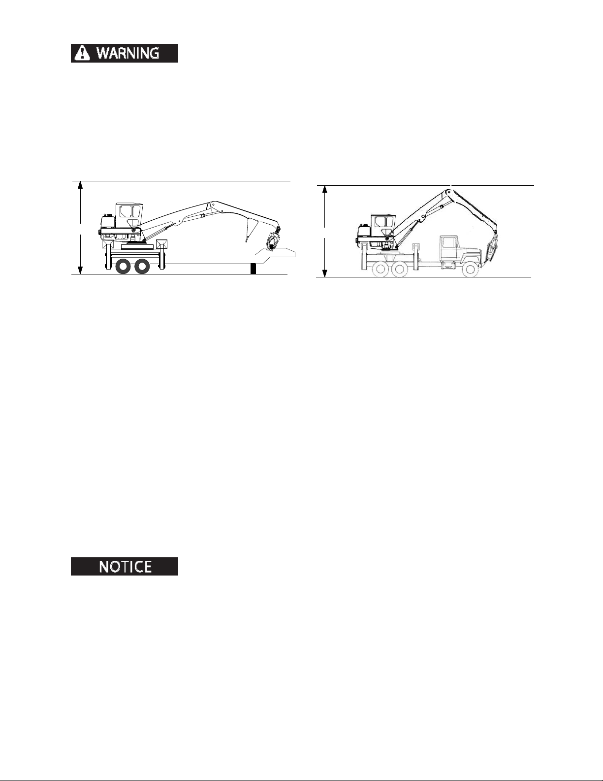
TRANSPORTING
0
13' 6" MAX.
TRAILER MOUNT
13' 6" MAX.
TRUCK MOUNT
TRANSPORTING
Failure to follow these important safety rules could result in seri-
ous personal injury or death.
• Remove any obstacles from trailer oor.
• Load and unload machine on level ground.
• Always use a ramp of proper height, loading angle, and strength.
• Engage trailer and truck brakes, and place wooden blocks around wheels.
LOADING PROCEDURE
1. Before transporting, investigate road width, bridges, road and trac conditions of
planned route, as well as governing laws and regulations. Obtain required permits and/or
authorization from appropriate agencies.
2. Mount loader as if for operation (see Operation section).
3. Swing upper frame clear of obstacles until it centers with grapple carrier.
4. Lower booms. Lower grapple until it rests in grapple carrier.
5. Raise stabilizers.
6. Shut engine down. Remove key from ignition.
7. Turn master battery disconnect switch to OFF.
8. Close and lock cab door.
9. Cover intake and exhaust openings to prevent damage to turbocharger and prevent water
and dust from entering engine.
10. Secure grapple to grapple carrier with chain.
11. Secure any attachment(s) with chain.
12. Before transporting, make sure no part of the machine exceeds 13’6” from the ground, or
special height permits may be required.
DO NOT wrap chains around machined surfaces. Travel vibration can cause
chain hammering.
2410 8-1 1111
Page 68

TRANSPORTING
NOTES
2410 8-2 1111
Page 69
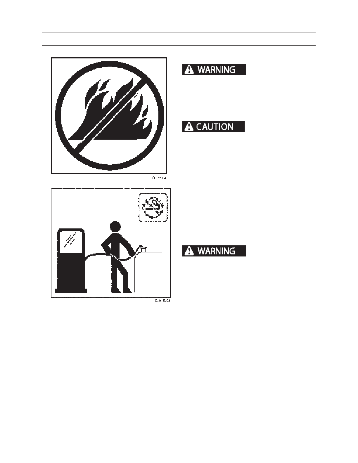
FUELS AND LUBRICANTS
FUELS AND LUBRICANTS
FUEL
FUEL TANK REFUELING
Fuel leaked or spilled
onto hot surfaces or electrical components can
cause a re, which can result in severe personal
injury or death. To help prevent possible injury,
turn the ignition switch OFF when changing fuel
lters or water separator elements. Clean up fuel
spills immediately.
Prevent re! Handle fuel
carefully!
• DO NOT ll fuel tank while engine is running.
• DO NOT smoke while lling or working on the fuel
system.
• DO check fuel tank vent. Clean if dirty or plugged.
• DO ll fuel tank at the end of each day.
• DO drain fuel tank of water once a week.
• DO clean up all spills immediately.
FUEL SPECIFICATIONS
DO NOT mix gasoline or
alcohol with diesel fuel. This mixture can cause an
explosion.
Refer to engine operator’s manual for recommended
diesel fuel grades.
STORING FUELS
• Keep fuel containers in a protected area.
• Remove water and sediment before transporting.
• DO NOT use deicers to remove water from fuel.
• DO NOT depend on lters to remove water.
• DO install water separators at storage tank outlets.
2410
• KEEP FUEL CLEAN.
91
1111
Page 70
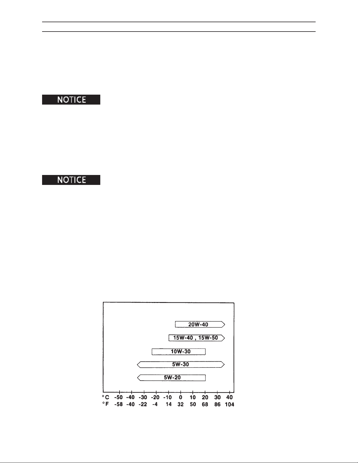
FUELS AND LUBRICANTS
ENGINE OIL
LUBRICATION, OIL PERFORMANCE, AND VISCOSITY RECOMMENDATIONS
Use of a quality engine lubricating oil combined with appropriate oil and lter change intervals are critical
factors in maintaining engine performance and durability. When changing or adding engine oil, use Premium
Engine Oil. For more information, refer to Cummins's engine operator’s manual.
When adding lubricants, do not mix dierent brands or grade weights. Manufacturers’
additives are not always compatible.
Cummins Engine Company Inc., recommends the use of a multi-graded lubricating oil since it has been found
to improve oil consumption control and improve engine cranking in cold temperatures while maintaining
lubrication at high operating temperatures.
A multi-graded oil is recommended with viscosity grades as shown in the Cummins chart below. The use of
single-grade lubricating oil is not recommended except for synthetic oils used in arctic conditions.
Cummins does not recommend the use of aftermarket additives in oil. See engine operator’s manual for more
information.
Limited use of low viscosity oils, may be used for easier starting and for providing
sucient oil ow at ambient temperatures below 23°F (-5°C). However, continuous use of low-viscosity oils can
decrease engine life due to wear.
ENGINE BREAKIN OILS
Do not use special “break-in” lubricating oils for new or rebuilt Cummins engines. Use the same type of oil during
the break in period as will be used during normal operations.
ARCTIC OPERATION
If an engine is operated in ambient temperatures consistently below -10°F (-23°C), and there are no plans to keep
the engine warm when it is NOT in operation, use a synthetic CD/SF engine oil with adequate low temperature
properties such as 5W-20 or 5W-30.
2410
Anticipated Ambient Temperature
Cummins Engine Oil Chart
92
1111
Page 71
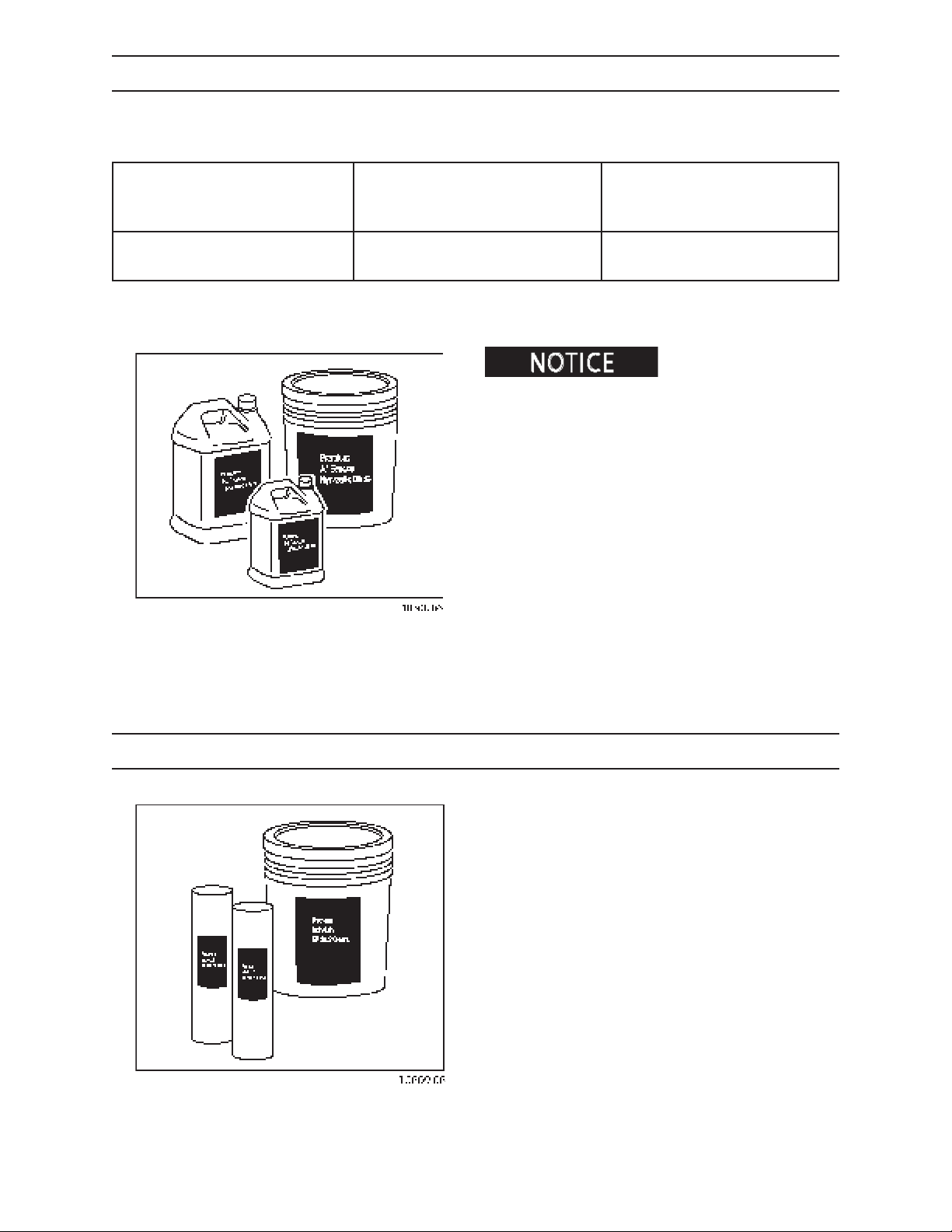
FUELS AND LUBRICANTS
HYDRAULIC OIL
Hydraulic systems have been lled from the factory with Premium All-Season Hydraulic Oil 46.
Use the following hydraulic oils in this machine.
AMBIENT TEMP AMBIENT TEMP AMBIENT TEMP
25°F TO 80°F 10°F TO 95°F 0°F TO 105°F
32°C TO 27°C 23°C TO 35°C 18°C TO 41°C
Premium All-Season Premium All-Season Premium All-Season
Hydraulic Oil 32 Hydraulic Oil 46 Hydraulic Oil 68
Check with an authorized
dealer for hydraulic uid recommendations and
compatibilities.
BE SURE hydraulic uid selection is compatible with
the hydraulic system.
BE SURE hydraulic uid selection assistance is from a
reputable supplier.
BE SURE hydraulic specications meet or exceed the
Premium All Season Hydraulic Oil specications. See
an authorized machine dealer.
BE SURE to use a mineral-base hydraulic oil.
GREASE
Most lubricated ttings require Premium Moly-Lith EP
#2 Grease. However, there are special requirements for
the swing bearing and swing drive motor (see Grease
for Swing Bearing and Swing Drive Motor in this
section).
2410
93
1111
Page 72
FUELS AND LUBRICANTS
LUBRICANT FOR PINION AND SWING GEAR TEETH
When lubricating the pinion gear and swing gear teeth, use moly-lith open gear lubricant.
When the gear path becomes contaminated, clean with solvent to remove contamination. Relubricate gear with
moly-lith open gear lubricant, available from an authorized dealer.
CYLINDER ROD CORROSION PREVENTIVE
If machine will be stored for an extended period, or stored in a corrosive environment
(such as salt air or industrial pollution), apply Chrome Kote Corrosion Preventive on all portions exposed to air.
See Storage section for more information.
ENGINE COOLANT SPECIFICATIONS
Engine coolant must meet or exceed the following specications:
• SAE J1941
• ASTM 4985
• GM 6038M
• TMC RP 302B
The engine coolant must contain low silicate (less than .1% anhydrous metasilicate) ethylene glycol base. The
supplemental coolant additive (SCA) should be Fleetgard DCA4 or equivalent.
When preparing engine coolant, follow these steps:
1. Thoroughly mix ethylene glycol base coolant with SCA in this ratio: 93% coolant to 7% additive.
2. Mix coolant/additive compound with distilled water in this ratio: 50% coolant/additive compound to 50%
distilled water.
2410
94
1111
Page 73
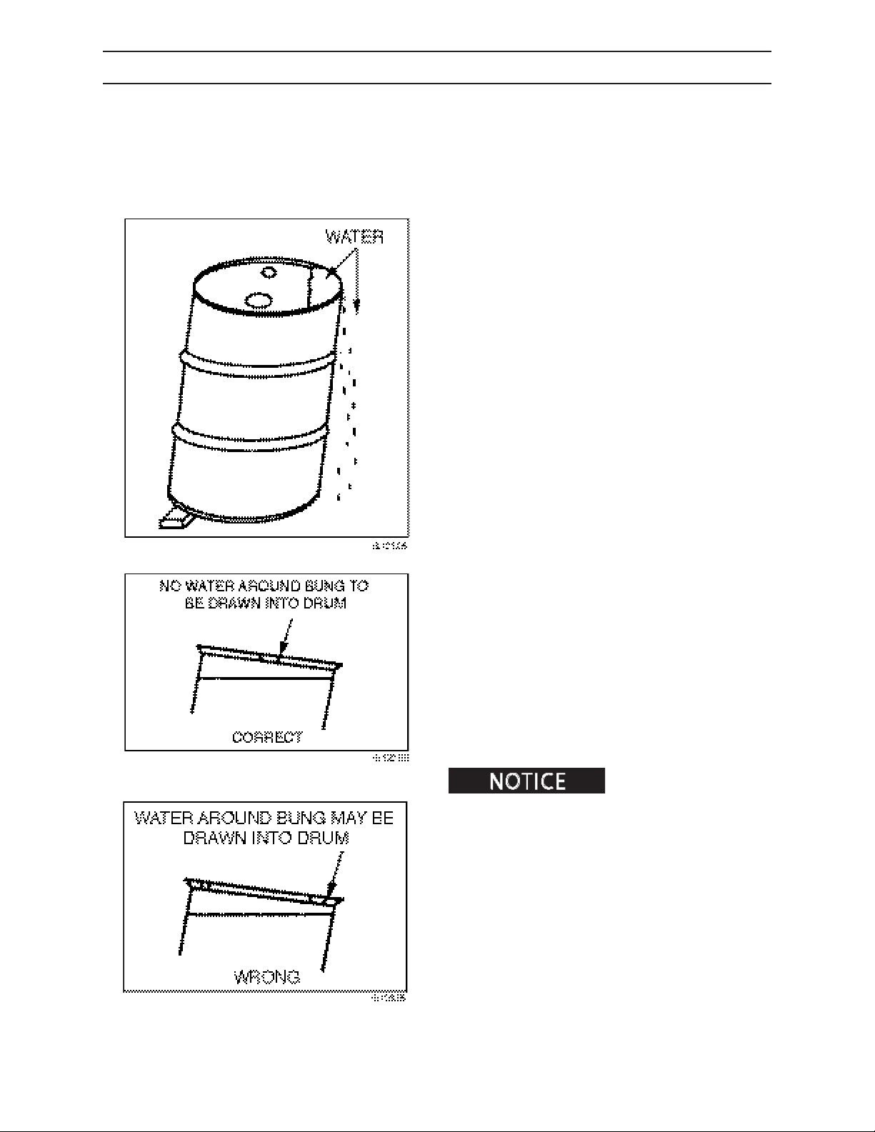
FUELS AND LUBRICANTS
STORING LUBRICANTS
Store lubricants in a clean area that will keep them protected from water, dirt, or other contamination.
Always use clean containers when handling lubricants.
Storing lubricant drums or other containers outdoors is poor practice. To minimize the harmful eect of
unavoidable outdoor storage, a few simple precautions and procedures can be very helpful.
1. Generally, lubricants in containers smaller than
drums (55-, 30-, and 16-gallon oil drums, and
400- and 120-pound grease drums) should never
be stored outdoors. When drums must be stored
outdoors, a temporary shelter or lean-to, or a
waterproof tarp will protect them from rain or
snow.
2. Drums should be placed on their sides with the
bungs approximately horizontal. In this position,
bungs are below the level of the contents so that
breathing of water or moisture is greatly reduced
and water cannot collect inside chine (ridge of
drum). For maximum protection, drums should
be stood on end with bung end down on a welldrained and contained surface. Where all of these
approaches are not practical, drum covers may
be used. Drum covers are available in metal and
plastic.
3. When drums must be stored outdoors with bung
end up, they should be blocked up with bungs
parallel to the block to keep water away from the
bung openings.
4. Drums that have a bung on the side should be
stored either on end or on their side with the
bung down. Regardless of their position, drums
should always be placed on blocks or racks several
inches o the ground to avoid moisture damage.
DISPOSE OF USED FLUIDS PROPERLY.
If machine will be stored
for an extended period, or stored in a corrosive
environment (such as salt air or industrial pollution),
using a sponge, apply Chrome Kote Corrosion
Preventive to portions exposed to air. See
section
for more information.
Storage
2410
95
1111
Page 74

FUELS AND LUBRICANTS
NOTES
2410
96
1111
Page 75
MAINTENANCE SAFETY
MAINTENANCE SAFETY
BEFORE MAINTENANCE
Maintaining this machine improperly could result in severe personal injury or
death. Read this manual before doing maintenance. Follow all safety instructions.
1. Read all safety and maintenance instructions in
this operator’s manual.
2. Position equipment on rm, level ground.
3. Lower attachment to the ground.
4. Shut engine down.
5. Move controls in all directions to relieve hydraulic
pressure.
6. Remove key from ignition.
PRACTICE SAFE MAINTENANCE
Read maintenance manuals and understand service
procedures before performing service/maintenance.
Understand service procedures before performing
maintenance. When performing maintenance, keep
area around machine clean and dry.
DO NOT service machine while it is moving. Keep away
from power-driven parts. Lower attachment to the
ground. Disengage power. Shut engine down. Move
controls in all directions to relieve hydraulic pressure.
Remove key from ignition. Allow machine to cool
down.
Support all raised equipment.
Keep all machine parts in good condition, and be
sure parts are properly installed. Repair damage
immediately. Repair all hydraulic and fuel leaks
immediately. Replace worn or broken parts. Remove
any buildup of grease, oil or debris.
Disconnect battery ground cable (-) before working on
the electrical system.
Lower stabilizers to the ground. Do not support
machine weight on stabilizers.
2410
101
1111
Page 76
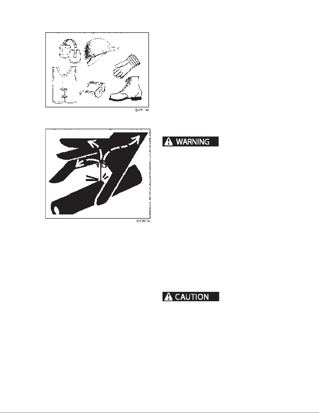
MAINTENANCE SAFETY
BEFORE MAINTENANCE
PROTECTIVE CLOTHING
Wear OHSA-approved protective clothing when
working on or near this machine, such as
• ear protection • gloves
• goggles • hard hat
• orange vest • steel-toed boots
Wear snug, protective clothing that is belted where
required.
Remove jewelry before working on or near this
machine.
HYDRAULIC SAFETY
pressure can penetrate skin and cause severe
personal injury or death. Wear eye and personal
protection equipment (PPE).
Fluids escaping under
If ANY uid is injected into the skin, seek
medical attention immediately. A serious
infection or reaction can result without proper medical
treatment.
Before working on the hydraulic system,
1. Lower boom and grapple to the ground.
2. Raise stabilizers so loader rests on carrier tires.
Then lower stabilizers to they touch the ground
without raising the loader.
3. Shut engine down.
4. Move joysticks in all directions to relieve hydraulic
pressure on boom.
5. Disengage pilot controls by moving pilot shut o
lever UP.
6. Remove key from ignition switch.
7. Purge air from hydraulic reservoir by depressing
relief valve button.
Hot hydraulic oil can
cause severe burns. DO NOT work on hydraulic
system if oil temperature exceeds 120°F (49°C).
Wear eye and personal protection equipment
(PPE)!
2410
Always use a board or cardboard when checking oil
hoses, lines, and ttings periodically for leaks, cracks or
defects. Be sure all clamps are in their proper position
and torqued as required and specied. Be sure hoses
are not twisted or touching parts.
102
1111
Page 77
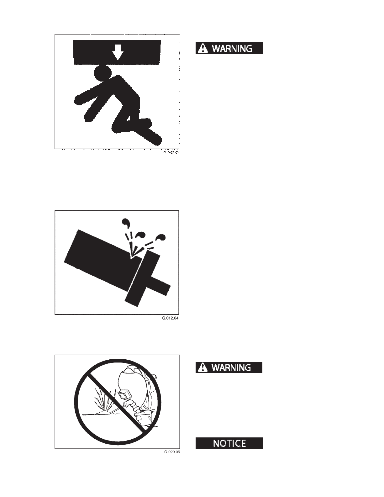
MAINTENANCE SAFETY
BEFORE MAINTENANCE
BOOM SAFETY
attachment can cause severe personal injury or
death.
DO NOT enter danger area under or around boom if
either of the following conditions apply:
1. Attachment is o the ground; or,
2. Engine is running.
Before ANY work is done in this area,
1. Lower attachment to the ground.
2. Shut engine down.
3. Move joysticks until pressure is released,
4. Remove key from ignition to prevent accidental
start up.
Falling boom or
SERVICING CONTROL VALVES, CYLINDERS,
PUMPS, AND MOTORS
Increasing relief valve settings could cause
machine or component failure resulting in severe
personal injury or death. Do not change pressure
settings. Do not switch lines from one valve to
another.
Special tools and training are required to service
control valves, cylinders, pumps, and motors. If these
parts need service, see an authorized dealer.
UNAUTHORIZED WELDING
Unauthorized welding
can cause structural failure and/or severe personal
injury or death.
2410
DO NOT weld on any structural member.
Any unauthorized welding or repair will void
the warranty.
Once authorized, be sure to turn battery disconnect
master switch OFF.
Unauthorized welding can
cause damage to the electrical system.
103
1111
Page 78
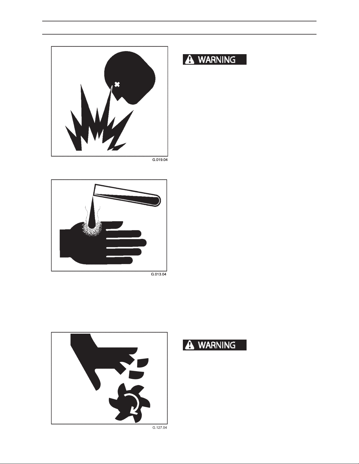
MAINTENANCE SAFETY
DURING MAINTENANCE
BATTERY SAFETY
explosive gases that can cause severe personal
injury or death.
Battery acid is poisonous and can cause severe
burns. If acid is taken internally, call a physician
immediately. If acid contacts skin or clothing, ush
with water immediately. Keep batteries away from
children.
Battery posts, terminals, and related accessories
contain lead and lead components, chemicals
known to the State of California to cause cancer
and reproductive harm. Wash hands after handling.
Keep sparks, ames, and cigarettes away from
batteries. Ventilate properly when charging or
using batteries in enclosed space. Always shield
eyes with goggles and wear a face shield when
working near batteries. Do not lean over batteries
during this operation. Always connect positive (+)
to positive (+) and negative (-) to negative (-). For
further instructions, see Jump Starting Battery in
Operation section. If battery acid contacts eyes,
ush them with water for 15 minutes and seek
immediate medical attention.
Batteries produce
Never charge a battery or jump start engine if
battery is frozen. Warm battery to 60°F (16°C) or
it may explode. Be sure vent caps are tight. When
jump starting from another machine, be sure
machines do not touch. This machine has a 12volt starting system. Use equal voltage for jump
starting.
COOLING FAN
Rotating fan can cause
severe personal injury or death. Cooling fan can
start at any time, even with motor o. Keep away
from fan at all times.
2410
104
1111
Page 79
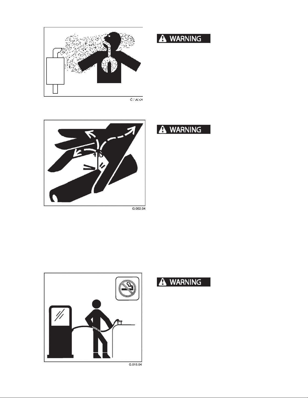
MAINTENANCE SAFETY
DURING MAINTENANCE, CONTINUED
DIESEL EXHAUST
contain elements that are hazardous to health.
Always run engine in a well ventilated area. If in an
enclosed area, vent exhaust outside.
FLUIDS UNDER PRESURE
pressure can penetrate skin and cause severe
personal injury or death. Wear eye and personal
protection equipment (PPE)!
DO NOT use hands to search for leaks. Always use a
board or cardboard when checking oil hoses, lines,
and ttings for leaks, cracks, or defects. Be sure all
clamps are in their proper position and torqued as
required and specied. Be sure hoses are not twisted
or touching parts.
Diesel exhaust fumes
Fluids escaping under
Escaping uids can penetrate skin and enter the
bloodstream. Before disconnecting lines, relieve all
pressure.
DO NOT apply pressure to a damaged line, hose, or
tting.
If any uid is injected into the skin, seek medical
attention immediately. A serious infection or reaction
can result without proper medical treatment.
FUELS AND LUBRICANTS
Fires and explosions can
cause severe personal injury or death.
• Handle fuels and lubricants carefully.
• DO NOT smoke when fueling or working with or
around fuel.
• Clean up, and properly dispose of all spilled
lubricants, grease and solvents.
• Use proper tools and procedures for making
repairs.
2410
• Wear approved eye and personal protection
equipment (PPE).
105
1111
Page 80
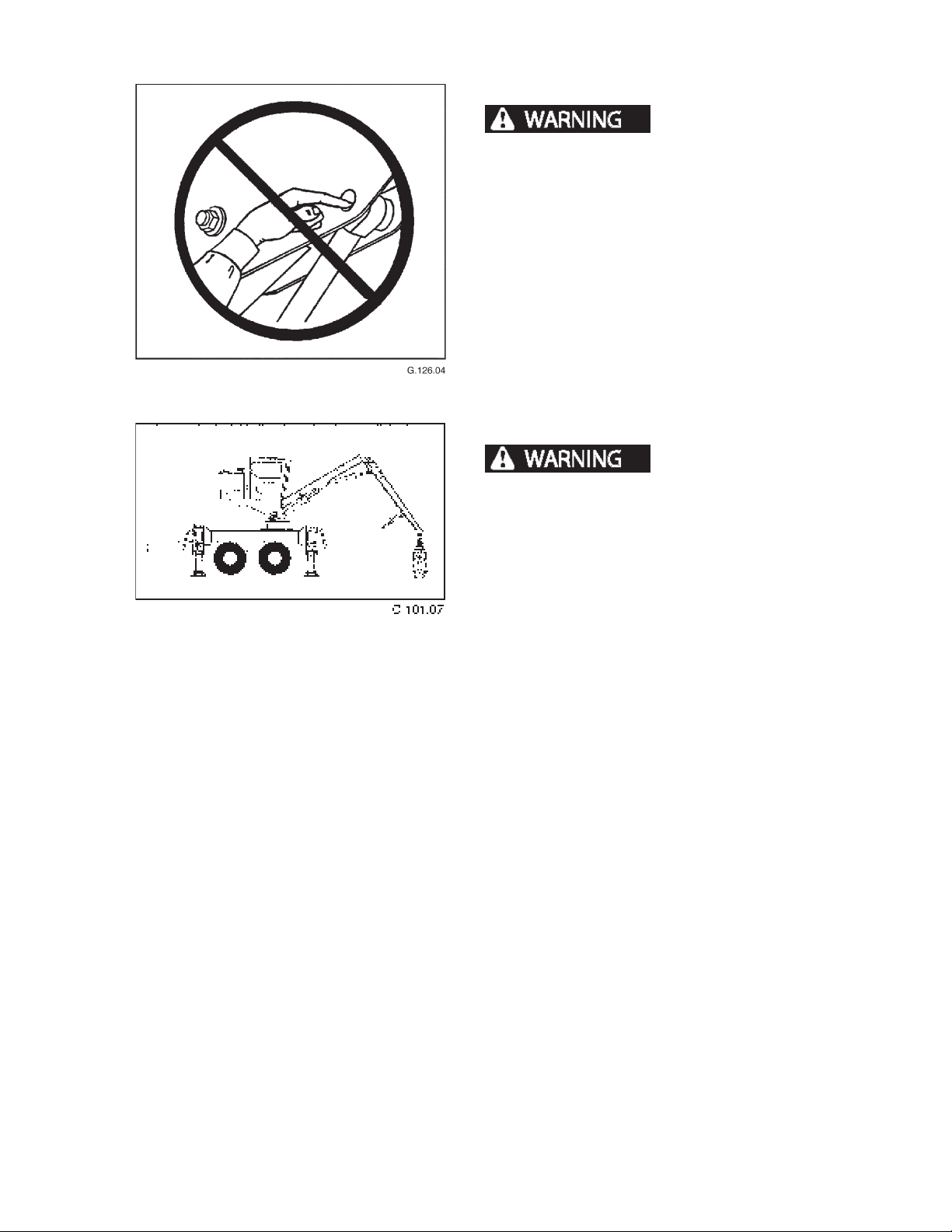
MAINTENANCE SAFETY
DURING MAINTENANCE, CONTINUED
PINCH POINTS
portion of the body where the machine moves can
cause severe personal injury or death. Never place
hands or any portion of the body where injury
could occur if machine moves. Never check pin hole
alignments with ngers.
SERVICING MACHINE WITH ENGINE RUNNING
engine running can cause severe injury or death.
When maintenance procedure requires engine be
running, ONLY qualied service technicians should
service machine.
Placing hands or any
Servicing machine with
2410
106
1111
Page 81
MAINTENANCE SAFETY
AFTER MAINTENANCE
DISPOSING OF WASTE
Follow local, state, federal, and international
regulations when disposing of waste. Waste may
include, but is not limited to oil, fuel, coolant, brake
uid, lters, and batteries.
Use leakproof containers when draining uids. Do not
use food or beverage containers. Do not pour waste
on the ground, down a drain, or into any water source.
Clean up all spilled fuel, oil, grease, etc. and dispose of
per local, state, federal, or international regulations.
STORING FLAMMABLE MATERIALS
• Do not smoke where ammable materials are
stored.
• Store fuels and lubricants in properly marked
containers.
• Store oily rags and other ammable materials in
protective containers.
2410
107
1111
Page 82

MAINTENANCE SAFETY
NOTES
2410
108
1111
Page 83
SCHEDULED AND PERIODIC MAINTENANCE SERVICES
SCHEDULED AND PERIODIC
MAINTENANCE SERVICES
LUBRICATION AND MAINTENANCE INTERVALS
Maintenance requirements for lubrication, adjustments and checks are shown on the maintenance
charts in this section.
Intervals of maintenance are based on normal operating conditions. If operating under more demanding
conditions, observe a shorter time interval between
maintenance.
Demanding conditions include but are not limited to:
• Hilly terrain
• Working in or passing through deep water or mud
• Dry work area with heavy blowing dust
• Extreme cold, -20°F (-6°C) and below
• Extreme heat, 100°F ( °C) and above
Use the hourmeter to help determine proper mainte-
nance intervals.
LUBRICATION NOTICE
Listed maintenance intervals are for normal use applications. When greasing lubrication ttings, if grease is not forced
out the bushing ends with the recommended shots, increase number of shots used until grease is forced out. If grease
cannot be forced out, check for blocked grease passageways.
If the lubricating areas are dry at the end of a normal operating day, increase the frequency of lubricating time periods
instead of increasing the amount of grease used at one lubrication period.
POSITION MACHINE FOR MAINTENANCE
To avoid serious personal
injury or property damage, follow the steps below
before performing any maintenance on this machine.
1. Park machine on level ground.
2. Lower boom and grapple to ground.
3. Raise stabilizers so loader rests on carrier tires.
Then lower stabilizers so they touch the ground
without raising the loader.
4. Shut engine down.
5. Move joysticks in all directions to relieve hydraulic
pressure on boom.
6. Disengage controls by moving control shut o
lever up.
7. Remove key from ignition switch.
2410
111
1111
Page 84
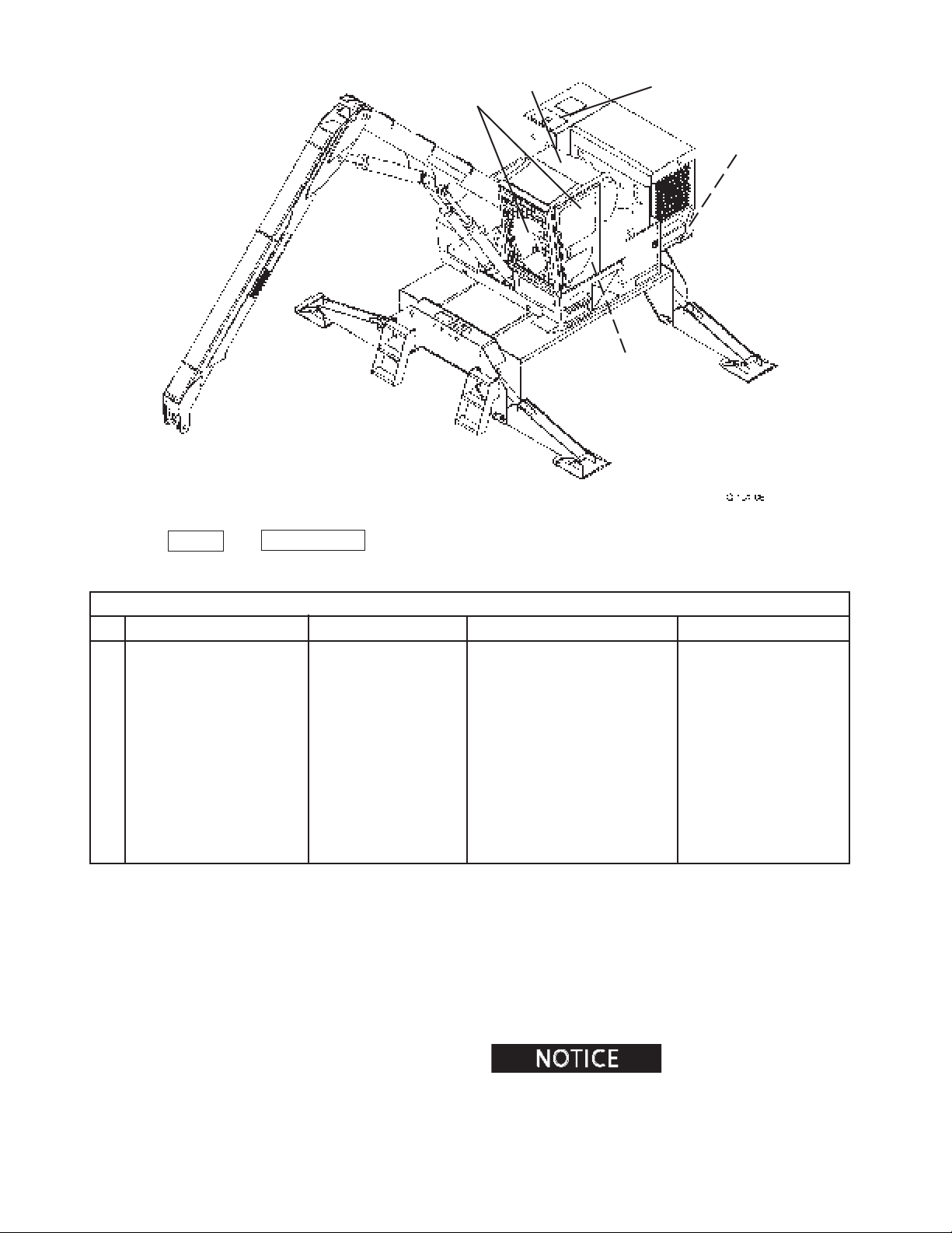
SCHEDULED AND PERIODIC MAINTENANCE SERVICES
5
6
MAINTENANCE CHART USAGE
8
2
3
4
Use the KEY # and COMPONENT for locating the proper service and maintenance procedures in this section.
AS REQUIRED
KEY COMPONENT SERVICE SPECIFICATION
1. Electrical System* Check Reset breakers or replace fuses
2. A/C Condenser Clean Compressed air
3. Recirculation Air Filter Clean/replace New lter Use Genuine parts
4. Windshield Washer Reservoir Check Fill washer uid
5. Windshield and Windows Clean Detergent and water
6. Polycarbonate Skylight Replace Polycarbonate material Use Genuine parts
7. Slasher/Delimber Saw* Adjust bar chain See details in section and
(if equipped) slasher/delimber manual
8. Hydraulic Oil Drain/replace Seasonally AS Hyd. Oil
9. Safety Decals* Clean/replace Use Genuine parts
10. Slip Resistant Mats* Clean/replace Use Genuine parts
MATERIAL USED
* Not shown
2410
Be sure to refer to the engine
operation and maintenance manual for additional engine maintenance recommendations and procedures.
11 2
1111
Page 85
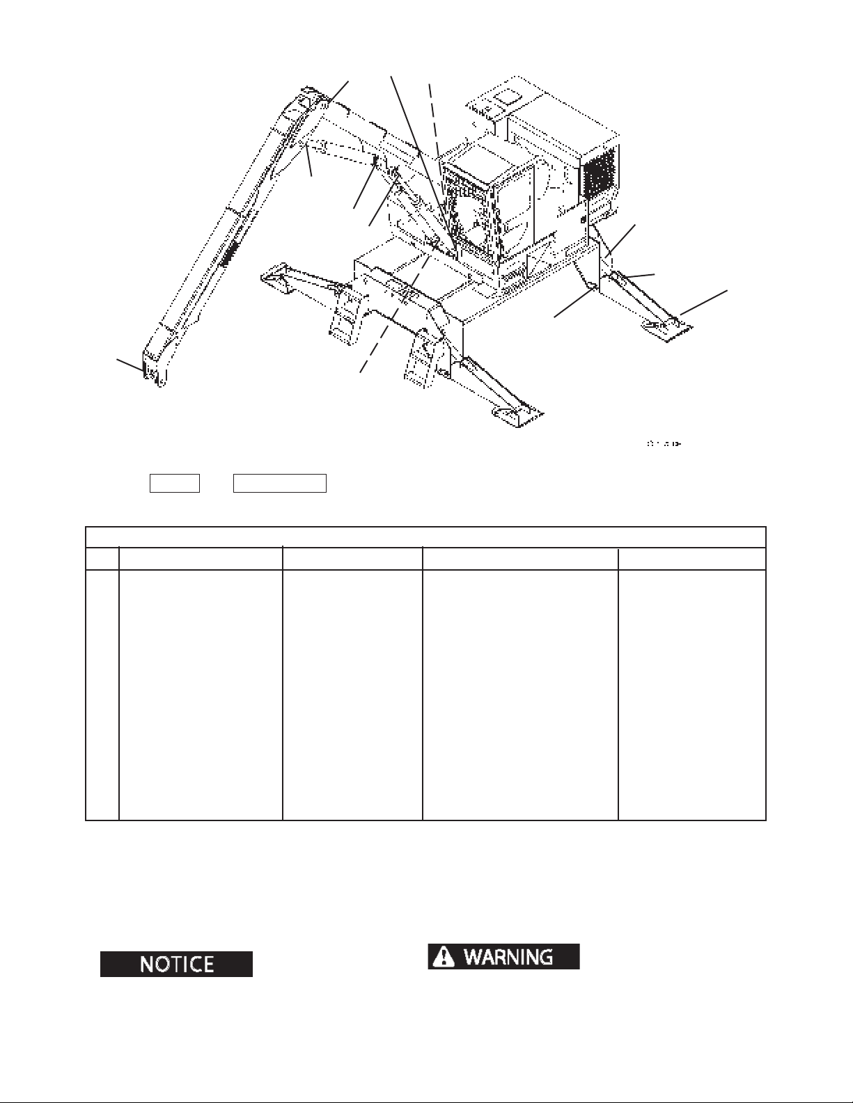
SCHEDULED AND PERIODIC MAINTENANCE SERVICES
17
19
16
21
20
15
18
13
14
11
22
MAINTENANCE CHART USAGE
Use the KEY # and COMPONENT for locating the proper service and maintenance procedures in this section.
DAILY OR EVERY 10 HOURS
KEY COMPONENT SERVICE SPECIFICATION
*DAILY VISUAL INSPECTION** Inspect Inspect loader for damage, see detail
11. Adapter Knuckle Lubricate Lubricate until grease is forced out Prem. Grease
12. Stabilizer Pad Pivot Pin Lubricate Lubricate until grease is forced out Prem. Grease
13. Stabillizer Cylinder Rod End Lubricate Lubricate until grease is forced out Prem. Grease
14. Stabilizer Arm Pivot Pin Lubricate Lubricate until grease is forced out Prem. Grease
15. Stabilizer Cylinder Base End Lubricate Lubricate until grease is forced out Prem. Grease
16. Main Boom Pivot Pin Lubricate Lubricate until grease is forced out Prem. Grease
17. Main Boom Cylinder Base End Lubricate Lubricate until grease is forced out Prem. Grease
18. Main Boom Cylinder Rod End Lubricate Lubricate until grease is forced out Prem. Grease
19. Main/Stick Pivot Pin Lubricate Lubricate until grease is forced out Prem. Grease
10. Stick Boom Cylinder Base End Lubricate Lubricate until grease is forced out Prem. Grease
21. Stick Boom Cylinder Rod End Lubricate Lubricate until grease is forced out Prem. Grease
22. Swing Bearing Lubricate Lubricate while rotating 2 complete Prem. Grease
revolutions
MATERIAL USED
12
* - Not shown
Moly-Lith EP #2 Grease.
Lubricate with Premium
** Do not weld on structures.
Immediately report structural problems (cracks) to an
authorized dealer for diagnosis and repair or replacment.
11 3
11112410
Page 86
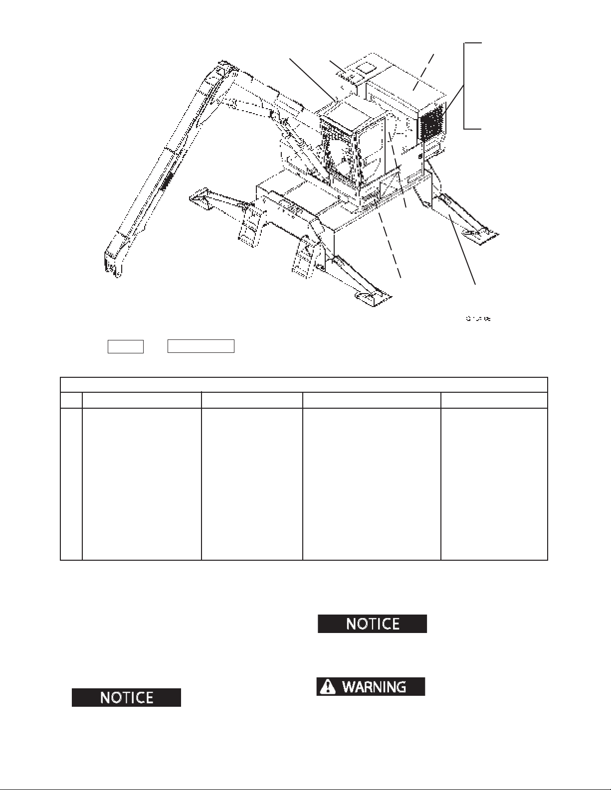
SCHEDULED AND PERIODIC MAINTENANCE SERVICES
27
MAINTENANCE CHART USAGE
24
26
23
25
28
29
30
31
32
34
Use the KEY # and COMPONENT for locating the proper service and maintenance procedures in this section.
DAILY OR EVERY 10 HOURS, continued
KEY COMPONENT SERVICE SPECIFICATION
23. Pinion Gear Lubricate Lubricate gear with open gear lube Open gear lube
24. Hydraulic Oil Reservoir Check level Add hydraulic oil if necessary Hyd. Oil
25. Air Cleaner Maintenance Clean or replace element Use Genuine parts
26. Fire Extinguisher Check charge Recharge or replace
27. Fuel Tank Check level Add fuel if necessary Diesel fuel
28. Cooling Fan Inspect Replace if damaged Use Genuine parts
29. Belts Inspect Replace if damaged Use Genuine parts
30. Fuel-water Separator Drain Drain until clear fuel drains
31. Engine Crankcase Oil Check level Add engine oil if necessary Prem. Eng. Oil
32. Radiator Coolant Check level Add coolant if necessary Water/antifreeze
33. Electrical Components* Inspect Check for fraying, loose connections See details in section
34. Loader Mounting Bolts Inspect Check for stability of loader position
operation and maintenance manual for additional engine maintenance recommendations and procedures.
MATERIAL USED
Be sure to refer to the engine
* - Not shown
Moly-Lith EP #2 Grease.
2410
Lubricate with Premium
Do not weld on struc-
tures. Immediately report structural problems
(cracks) to an authorized dealer for diagnosis and
repair or replacment.
11 4
1111
Page 87

SCHEDULED AND PERIODIC MAINTENANCE SERVICES
37
40
35
35
39
36
41
MAINTENANCE CHART USAGE
Use the KEY # and COMPONENT for locating the proper service and maintenance procedures in this section.
WEEKLY OR EVERY 50 HOURS
KEY COMPONENT SERVICE SPECIFICATION
*. WEEKLY INSPECTION Inspect Check for damage, see detail
35. Boom / Cylinder Attaching Pins Check Tighten Wrench
36. Stabilizer Attaching Pins Check Tighten Wrench
37. Oil Reservoir Hardware Check Tighten Wrench
38. Hydraulic connections* Inspect Tighten Wrench
39. Radiator and Oil Cooler Clean Remove debris Water
40. Hydraulic Oil Reservoir Check oil If contaminated, replace Prem AS Hyd Oil
41. Swing Drive Gear Box Check lube level Add lubricant, if necessary GL-5 Gear Lube
* Not shown
MATERIAL USED
Be sure to refer to the engine
operation and maintenance manual for additional engine maintenance recommendations and procedures.
** Do not weld on structures. Immediately report structural problems
(cracks) to an authorized dealer for diagnosis and
repair or replacment.
11 5
11112410
Page 88
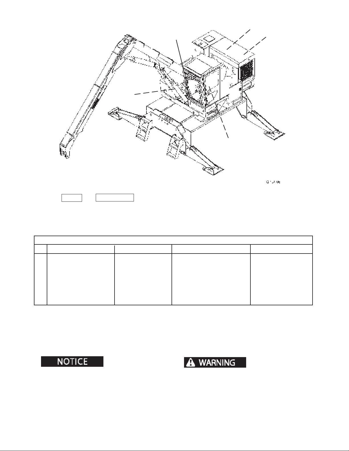
SCHEDULED AND PERIODIC MAINTENANCE SERVICES
44
46
45
43
42
MAINTENANCE CHART USAGE
Use the KEY # and COMPONENT for locating the proper service and maintenance procedures in this section.
MONTHLY OR EVERY 250 HOURS
KEY COMPONENT SERVICE SPECIFICATION
42. Engine Oil and Filter Change Drain and replace Oil and lter
43. Air Intake and Exhaust Inspect Check connections Wrench
44. Battery Check Check connections, electrolyte level Clean, distilled
water
45. Seat Inspect/Lube Silicone spray
46. Swing Drive Fasteners Check Tighten to 600 ft-lbs* (813 N•m) Torque wrench
*Use with Loc-Tite® or equivalent
MATERIAL USED
Be sure to refer to the engine
operation and maintenance manual for additional engine maintenance recommendations and procedures.
2410
** Do not weld on structures. Immediately report structural problems
(cracks) to an authorized dealer for diagnosis and
repair or replacment.
11 6
0209
1111
Page 89
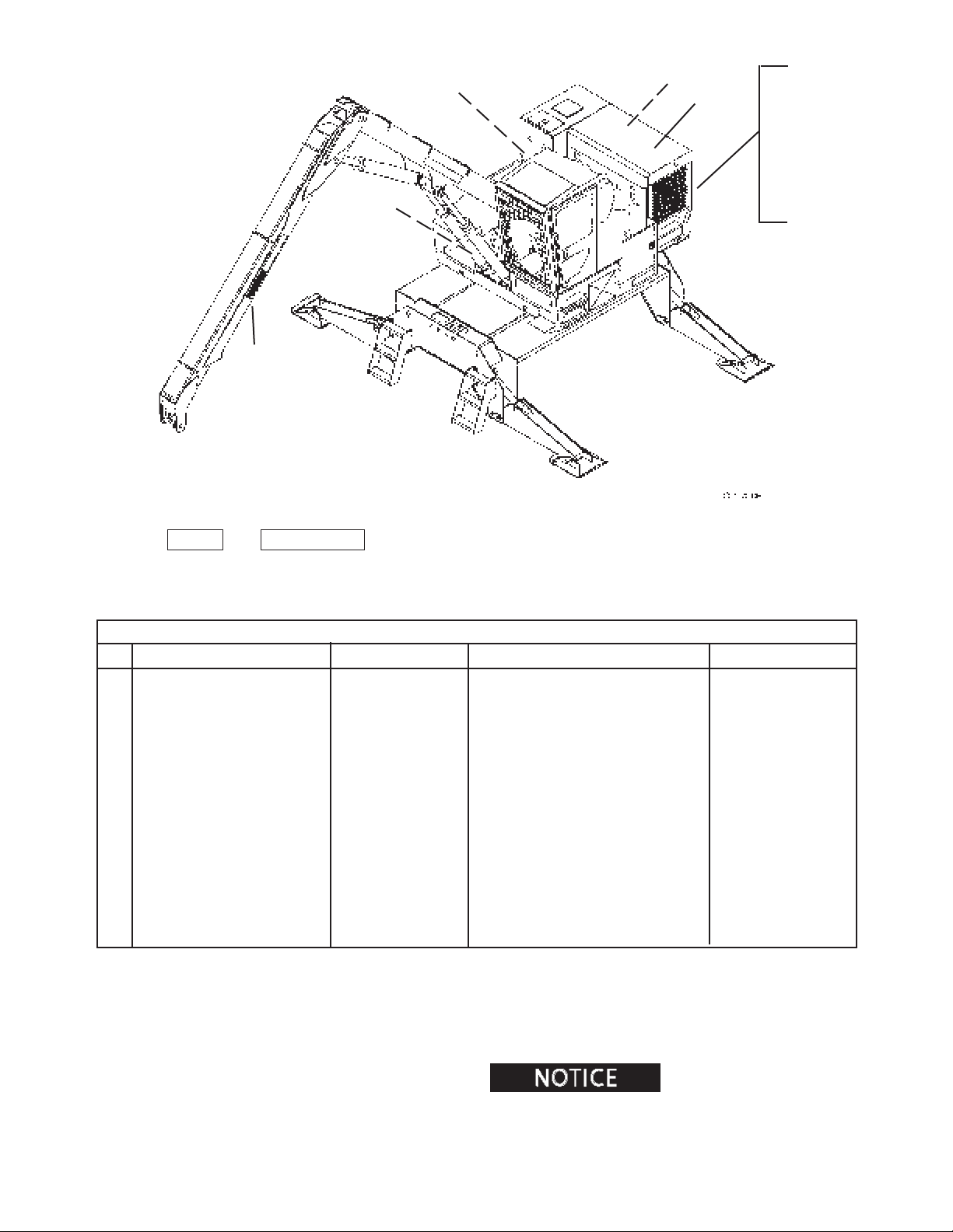
59
SCHEDULED AND PERIODIC MAINTENANCE SERVICES
56
57
58
54
55
60
47
48
49
50
51
52
53
MAINTENANCE CHART USAGE
Use the KEY # and COMPONENT for locating the proper service and maintenance procedures in this section.
EVERY 500 HOURS
KEY COMPONENT SERVICE SPECIFICATION
47. Hydraulic Oil Return Line Filter Install new* Replacement lter Use Genuine parts
48. Cooling System Check Check for leaks, sample conditioner Water conditioner
49. Fuel Lift Pump Pre-lter Install new** Replacement lter Use Cat parts
50. Primary Fuel Filter Install new** New lter Use Cat parts
51. Fuel System Prime See engine operator’s manual
52. Pilot Supply Filter Install new* New lter Use Genuine parts
53. Pilot Return/Case Drain Filter Install new* New lter Use Genuine parts
54. Outer Swing Bearing Fasteners Check Tighten to 600 ft-lbs (813 N•m) Torque wrench
55. Inner Swing Bearing Fasteners Check Tighten to 600 ft-lbs (813 N•m) Torque wrench
56. Swivel Torque Arm Fasteners Check Tighten to 76-84 ft-lbs (103-114 N•m) Torque wrench
57. Swivel Fasteners Check Tighten to 266-294 ft-lbs (360-399 N•m) Torque wrench
58. Pinion Gear Fastener (if equipped) Check Tighten to 420 ft-lbs (529 N•m) Torque wrench
59. Stationary Heel Fasteners Check*** Tighten to 112-178 ft-lbs (220-241 N•m) Torque wrench
60. Slasher/Delimber Return Line Filter Install new* New lter Use Genuine parts
MATERIAL USED
* Change interval can vary depending on operating conditions
** Change interval can vary depending on cleanliness of fuel
*** Tighten head of bolt while holding nut
operation and maintenance manual for additional engine maintenance recommendations and procedures.
11 7
Be sure to refer to the engine
11112410
0209
Page 90
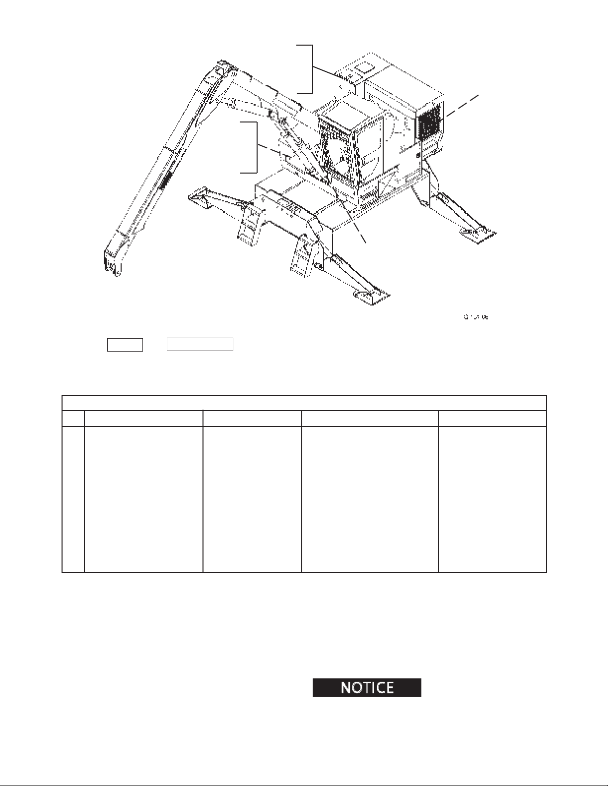
SCHEDULED AND PERIODIC MAINTENANCE SERVICES
61
62
63
65
66
67
68
64
MAINTENANCE CHART USAGE
Use the KEY # and COMPONENT for locating the proper service and maintenance procedures in this section.
EVERY 1000 HOURS
KEY COMPONENT SERVICE SPECIFICATION
61. Hydraulic Oil Drain/replace See details in section Premium AS Oil
62. Hydraulic Oil Reservoir Breather Replace Install new breather element Use Genuine parts
Filter
63. Pressure Vacuum Relief Valve Replace Install new relief valve Use Genuine parts
64. Cooling System Flush and ll Replace coolant See engine manual
65. Swing Drive Gear Box Lube Drain/replace Replace with 0.9 gal (3.4 L) lubricant GL-5
Gearlube
66. Swing Drive Check level Add grease if necessary Prem.
Grease
67. Swing Drive Drain and ll See details within section Mobilgear 630
68. Collector Ring Check/clean Spray contacts, check brushes Contact cleaner
and wire connections
MATERIAL USED
2410
Be sure to refer to the engine
operation and maintenance manual for additional engine maintenance recommendations and procedures.
11 8
1111
Page 91
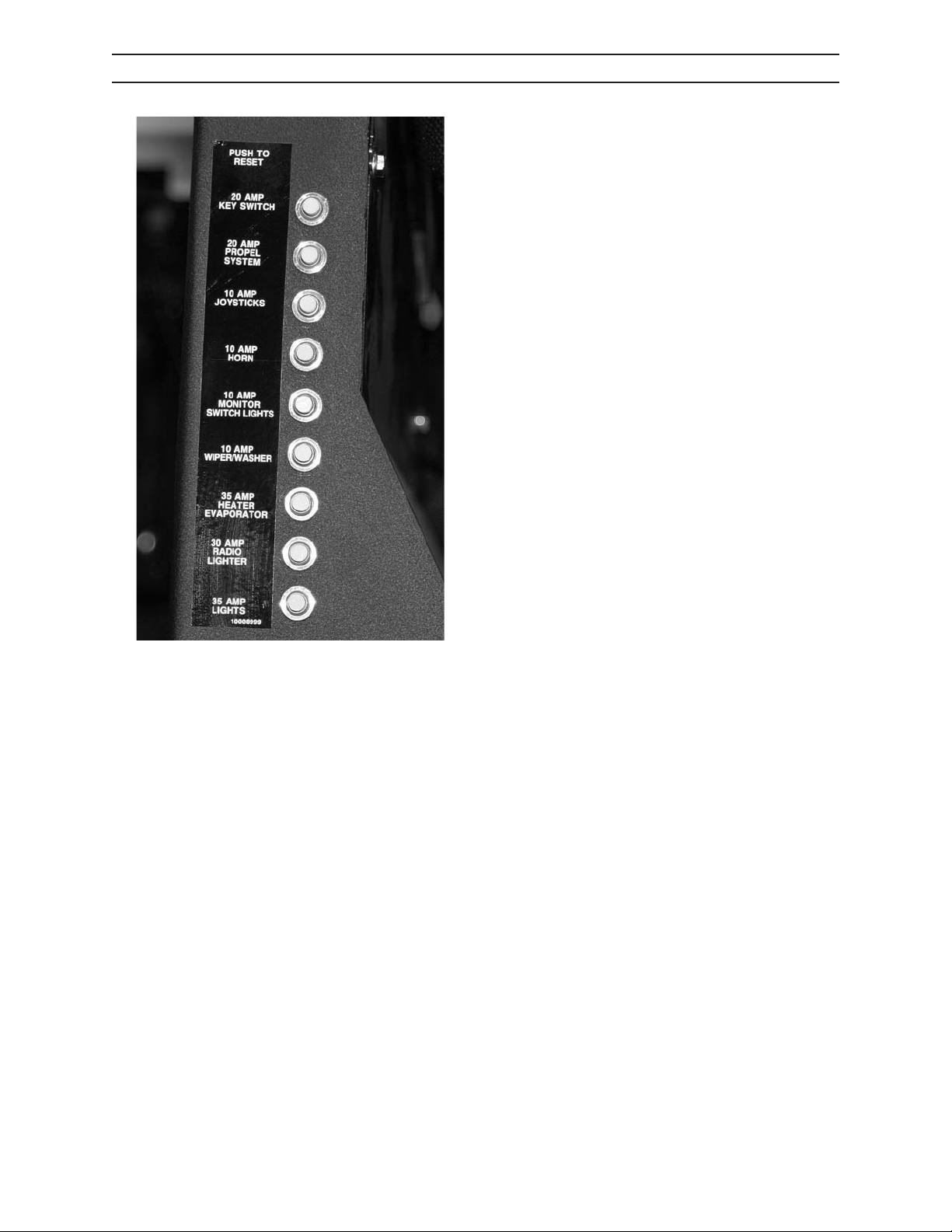
SCHEDULED AND PERIODIC MAINTENANCE SERVICES
AS REQUIRED
1. CHECK ELECTRICAL SYSTEM
Check circuit breakers.
Circuit breakers protect an electrical circuit from current overload.
If an overload occurs, the circuit breaker will trip, exposing the white reset button, and breaking the ow
of current. This will prevent damage to the circuit.
To reset a circuit breaker, depress the tripped circuit
breaker to its original position.
If breakers will not reset, replace the circuit breaker
and/or have an authorized dealer diagnose and repair
the problem.
IMG.2490
2410
119
1111
Page 92
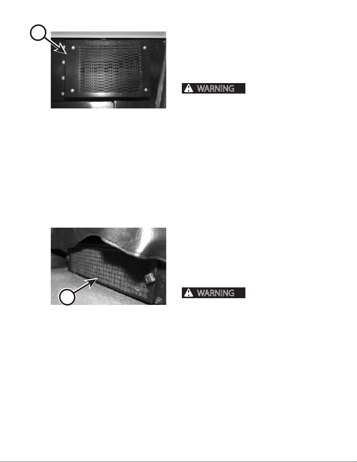
WARNING
WARNING
A
SCHEDULED AND PERIODIC MAINTENANCE SERVICES
AS REQUIRED
2. CLEAN A/C CONDENSER
If the air conditioner is not cooling properly, the condenser cooling ns may require cleaning to remove
debris and dirt.
1. Gain access to condenser by removing cap screws
from the access door (A).
air release debris and ying particles that
IMG.2453
can cause serious personal injury. Wear a face
shield and protective clothing.
2. With a maximum of 30 psi (210 kPa) compressed
air, clean condenser cooling ns. If ns cannot
be cleaned with compressed air, wash them with
water.
3. Secure access door with cap screws removed in
Step 1.
Cleaning with compressed
B
IMG.2458
3. CLEAN/REPLACE RECIRCULATION AIR
FILTER
1. The recirculating air lter is located beneath the
operator’s seat inside the cab. Loosen retaining
knobs and remove lter cover.
2. Remove, and clean lter (B) using one of the following methods.
Cleaning with compressed
air release debris and ying particles that
can cause serious personal injury. Wear a face
shield and protective clothing.
a. Lightly tap lter on at surface, dirty side
down.
b. Direct 30 psi (210 kPa) maximum compressed
air through lter from the opposite direction
of air ow.
c. Wash lter with mild soap and water. Rinse
until clean with water from hose having a
maximum pressure of 30 psi (210 kPa). Lightly
shake excess water from lter and allow to dry
before installing.
2410
3. Reinstall lter. If lter is damaged, replace with
new.
1110
1111
Page 93
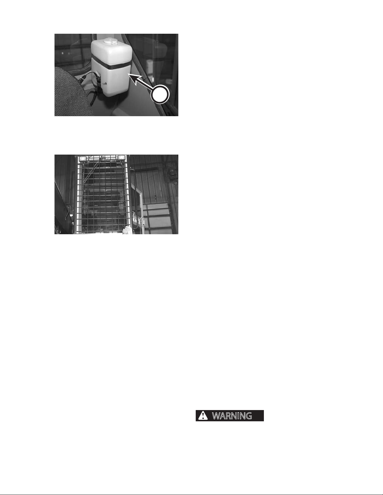
SCHEDULED AND PERIODIC MAINTENANCE SERVICES
WARNING
AS REQUIRED
4. FILL WINDSHIELD WASHER FLUID
RESERVOIR
The washer reservoir (A) is located inside the cab, on
the left side of the seat.
Add commercial windshield washer uid as necessary.
A
IMG.2429
5. CLEAN WINDSHIELD AND WINDOWS
The cab windshield and windows are made of tinted
safety glass. The skylight is polycarbonate window
material.
Do not use abrasive or highly alkaline cleaner.
IMG.2400
Do not scrape window with a metal scraper or sharp
object.
Do not use benzene, gasoline, acetone or carbon tetrachloride to clean polycarbonate windows.
Do not clean polycarbonate window material skylight
in hot sun or at elevated temperatures.
Fresh paint, grease and tree sap can be removed before drying by rubbing lightly with naptha, isopropyl
alcohol, or butyl cellosolve (2-butoxy ethanol). Then
wash with a mild soap or detergent solution. Rinse
thoroughly with clean water.
Scratches and abrasions can be removed or minimized
by using a mild automobile wax. Test a small area of
the polycarbonate window material with the product
used to be sure it does not scratch or cloud the window.
1. Open front window guard.
2. Flush away as much loose dirt and dust as possible.
3. Wash windshield and windows and skylight with a
mild soap or detergent and lukewarm water. Use a
clean sponge or soft cloth. Rinse with clean water.
Dry with a soft cloth or chamois to prevent water
spots.
2410
Falling or swinging
logs can cause severe personal injury or death.
Never operate the machine without the cab guard
securely in place and undamaged.
4. Close front window guard and secure into place.
1111
1111
Page 94
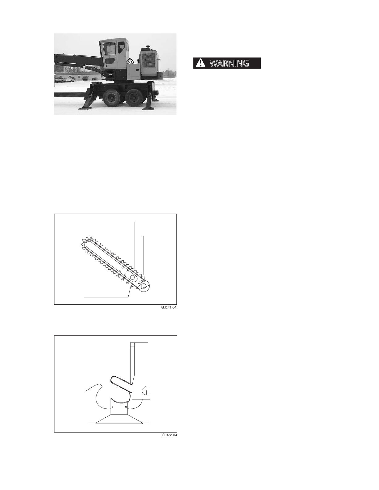
SCHEDULED AND PERIODIC MAINTENANCE SERVICES
WARNING
AS REQUIRED
6. CHECK/REPLACE POLYCARBONATE
WINDOW SKYLIGHT
al injury or death from objects breaking through
polycarbonate window material, replace them
when they
• are yellow or hazed;
• are scratched on either side with scratches that
IMG.2557B
can be felt with a ngernail (.0003 inch or greater);
• have small cracks coming from edges or mounting
holes; or,
• have contacted uids that have caused cloudiness.
When any of the above conditions exist, the polycarbonate windows have lost enough of their strength
that they will no longer protect the operator as
designed.
To prevent serious person-
Slasher saw bar position for
chain adjustment
7. ADJUST SLASHER/DELIMBER SAW
BAR CHAIN
1. Remove personnel from saw area.
2. Activate saw function, and run saw bar to halfway
down from the saw box (as shown), then release
button. This will stop the saw chain from rotating,
and will position the saw bar for chain adjustment.
3. Shut engine down and remove key.
4. Adjust chain following instruction in the slasher/
delimber operator’s manual.
5. After chain is adjusted, remove personnel from
saw area.
6. Start engine.
7. Activate saw function, and return the bar to the
saw box.
2410
Delimber saw bar position for
chain adjustment
1112
1111
Page 95
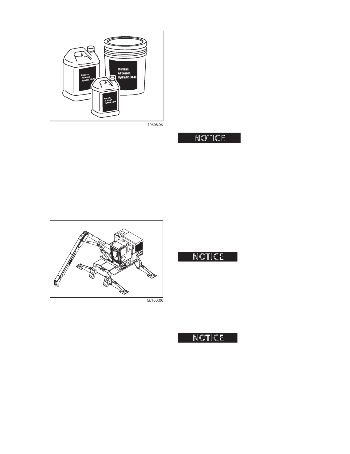
SCHEDULED AND PERIODIC MAINTENANCE SERVICES
NOTICE
NOTICE
NOTICE
AS REQUIRED
8. DRAIN AND REPLACE HYDRAULIC OIL
Hydraulic oil must be changed based on the ambient
(outside) air temperature. Certain grades of hydraulic
oil work best in certain temperature ranges.
Follow Caterpillar’s hydraulic oil specications. If oil
is not changed seasonally, as required, the hydraulic
system can be damaged.
Refer to Fuels and Lubricants section for hydraulic oil
recommendations.
Procedures for changing hydraulic oil can be found
later in this section.
Hydraulic oil capacity is 65 gallons (246 L).
or weights of hydraulic oil.
DO NOT mismatch brands
9. HAZARD DECALS
Inspect safety decals and replace as needed when
damaged or unreadable.
Decals will not adhere to
dirty or wet surfaces. Thoroughly clean and dry any area
where a decal or slip resistant mat is to be placed.
10. SLIP RESISTANT MATS
Inspect and clean resistant mats. Replace any slip resistant mat that has been damaged or has come loose.
Decals will not adhere to
dirty or wet surfaces. Thoroughly clean and dry any area
where a decal or slip resistant mat is to be placed.
2410
1113
1111
Page 96
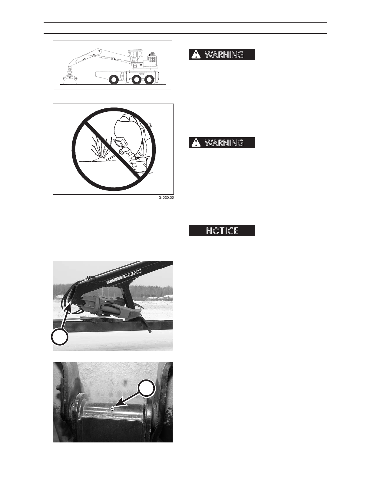
SCHEDULED AND PERIODIC MAINTENANCE SERVICES
WARNING
WARNING
NOTICE
DAILY OR EVERY 10 HOURS
PERFORM A DAILY VISUAL INSPECTION
inspection of machine can result in machine damage and severe personal injury or death.
In addition to the required daily inspection outlined in
G.048.03
Pre-Start Inspection section perform a daily inspection
of the following components:
• Structures • Swing bearing
• Booms • Load-bearing items
• Cylinders • All mountings
• Turntable
can cause structural failure and/or severe personal
injury or death.
DO NOT weld on any structural member.
Any unauthorized welding or repair will void
the warranty.
Failure to perform a daily
Unauthorized welding
A
Once authorized, turn battery disconnect master
switch OFF and place welding ground (stinger) as close
to the weld site as possible. Do not allow weld current
to pass through bearings, bushings or pivot points.
Welding can cause damage
to the electrical system.
11. LUBRICATE ADAPTER KNUCKLE
Lubricate adapter knuckle (A) with Premium Moly-Lith
EP #2 until grease is forced out.
IMG.2560
12. LUBRICATE STABILIZER PAD PIVOT
PINS
2410
B
IMG.2470
Lubricate stabilizer pad pivot pins (B) with Premium
Moly-Lith EP #2 until grease is forced out.
1114
1111
Page 97
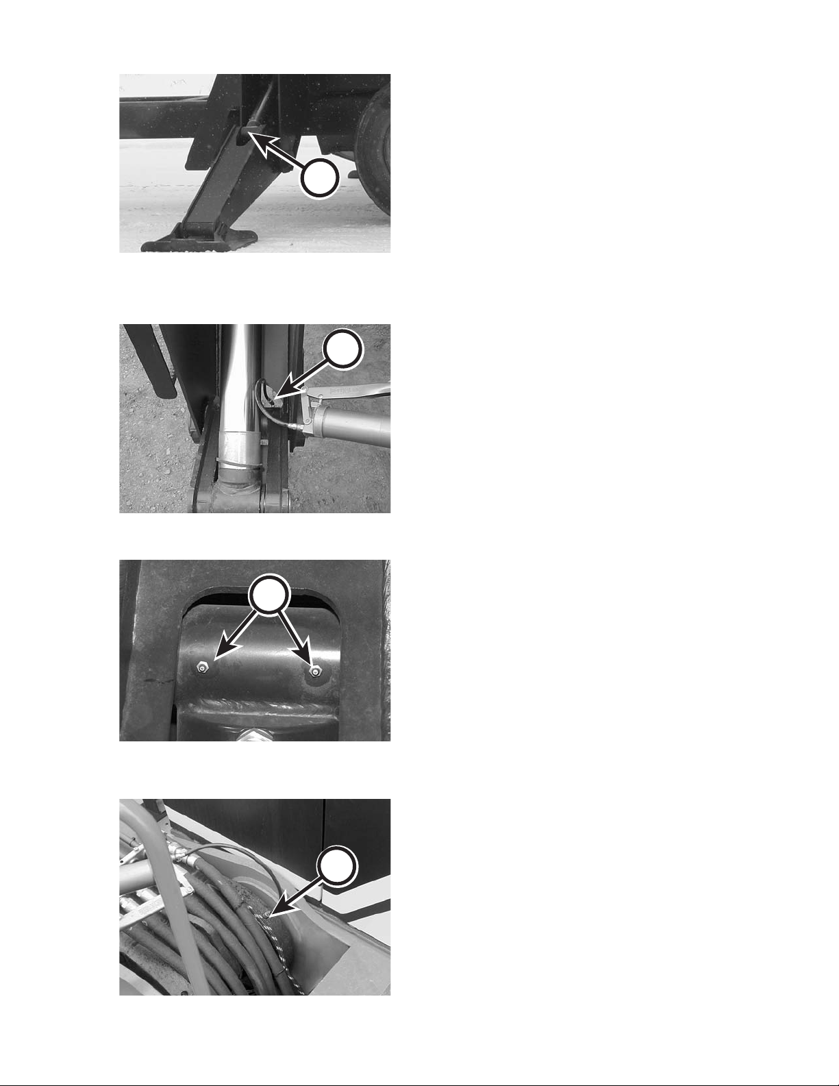
SCHEDULED AND PERIODIC MAINTENANCE SERVICES
DAILY OR EVERY 10 HOURS
13. LUBRICATE STABILIZER CYLINDER
ROD ENDS
Lubricate stabilizer cylinder rod ends (A) with Premium
Moly-Lith EP #2 until grease is forced out.
A
IMG.2557A
14. LUBRICATE STABILIZER ARM PIVOT
B
PINS
Lubricate stabilizer arm pivot pins (B) with Premium
Moly-Lith EP #2 until grease is forced out.
C
045.03
15. LUBRICATE STABILIZER CYLINDER
BASE ENDS
Lubricate stabilizer cylinder base ends (C) with Premium Moly-Lith EP #2 until grease is forced out.
IMG.2469
16. LUBRICATE MAIN BOOM PIVOT PINS
Lubricate main boom pivot pins (D) with Premium
Moly-Lith EP #2 until grease is forced out.
D
2410
047.03
1115
1111
Page 98
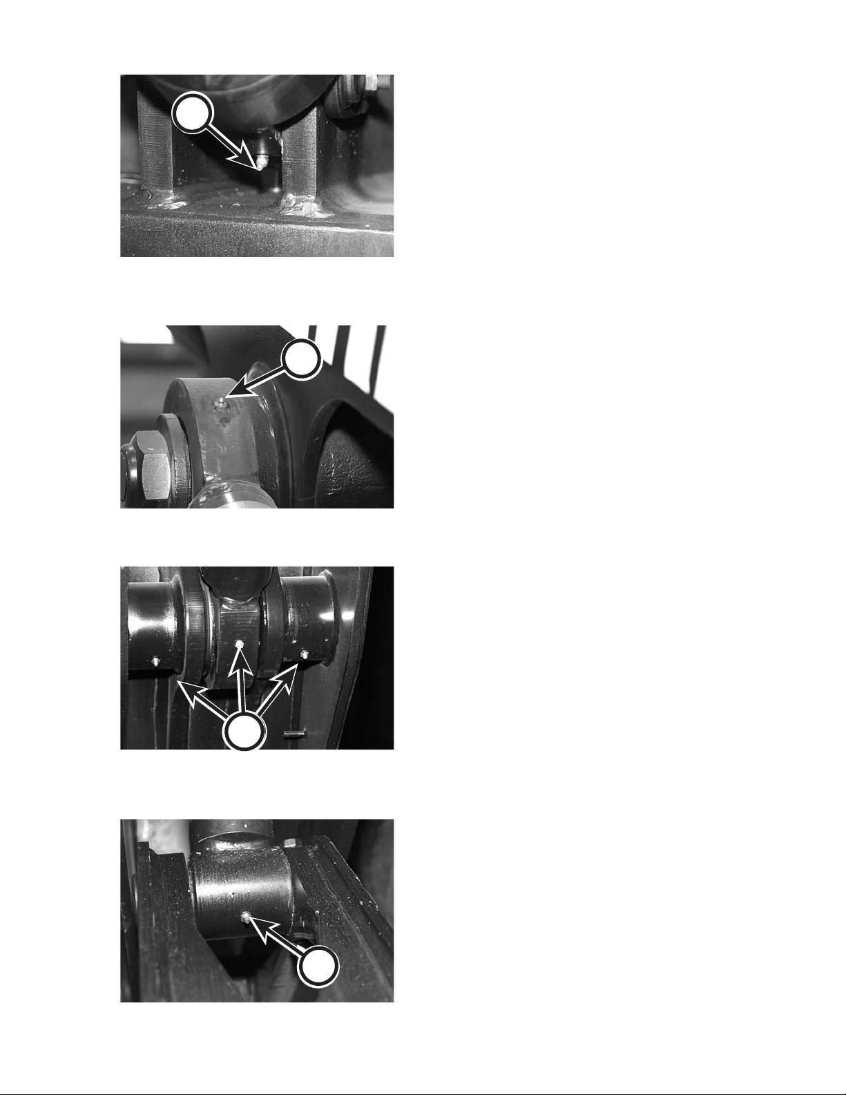
A
SCHEDULED AND PERIODIC MAINTENANCE SERVICES
DAILY OR EVERY 10 HOURS
17. LUBRICATE MAIN BOOM CYLINDER
BASE ENDS
Lubricate main boom cylinder base ends (A) with Premium Moly-Lith EP #2 until grease is forced out.
IMG.2464
18. LUBRICATE MAIN BOOM CYLINDER
B
ROD ENDS
Lubricate main boom cylinder rod ends (B) with Premium Moly-Lith EP #2 until grease is forced out.
C
IMG 2466
19. LUBRICATE MAIN/STICK PIVOT PINS
Lubricate main/stick pivot pins (C) with Premium MolyLith EP #2 until grease is forced out.
IMG.2479
20. LUBRICATE STICK BOOM CYLINDER
BASE ENDS
Lubricate stick boom cylinder base ends (D) with Premium Moly-Lith EP #2 until grease is forced out.
2410
D
IMG.2473
1116
1111
Page 99
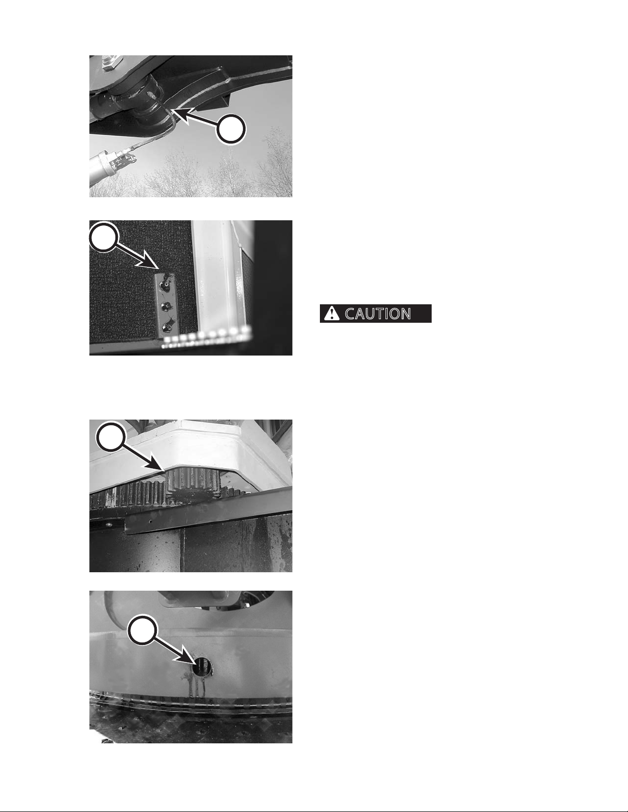
SCHEDULED AND PERIODIC MAINTENANCE SERVICES
CAUTION
DAILY OR EVERY 10 HOURS
21. LUBRICATE STICK BOOM CYLINDER
ROD ENDS
Lubricate stick boom cylinder rod ends (A) with Premium Moly-Lith EP #2 until grease is forced out.
A
052.03
22. LUBRICATE SWING BEARING
B
C
IMG.2571
Lubricate swing bearing with Premium Moly-Lith EP #2
while rotating loader 2 complete revolutions.
There are 3 grease ttings (B) located on the oor of
the right side of the cab that can be reached with a
grease gun from the operator’s seat.
Rotate turntable slowly.
Boom can strike people or property, which can cause
personal injury or property damage. Be sure loader
is clear of obstructions, remove personnel, and make
sure those not performing maintenance are clear of
the machine.
23. LUBRICATE PINION GEAR
Coat gear teeth (C) with Heavy Duty Open Gear Lube
to prevent bare metal contact. Spray lubricant through
access hole (D) .
2410
D
054.03
PINION LUBE.TIF
1117
1111
Page 100
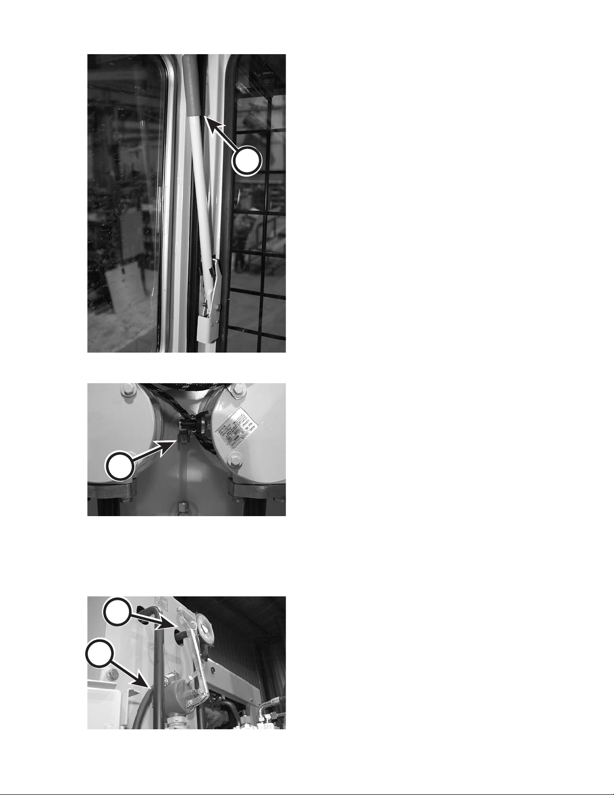
SCHEDULED AND PERIODIC MAINTENANCE SERVICES
DAILY OR EVERY 10 HOURS
24. CHECK HYDRAULIC OIL RESERVOIR
LEVEL
1. Position loader properly for an accurate reading.
Booms should be horizontal, and grapple should
be closed. Lower stabilizers so they touch the
ground without raising the loader.
2. Shut engine down and move joysticks in all direc-
A
tions to relieve hydraulic pressure.
3. Disengage controls by moving control shut o
lever UP (A).
4. Visually check the oil level by observing the sight
gauge (B) on the hydraulic reservoir while oil is
warm. Sight gauge is located in hydraulic lter
compartment, accessed through the top of the
engine compartment.
5. Add clean, ltered oil, if necessary (refer to Fill
Hydraulic Reservoir below).
D
C
IMG.2576
B
IMG.2500
FILL HYDRAULIC RESERVOIR
1. Gain access to hydraulic reservoir hand ll pump
(C) on the loader.
2. Uncoil ll hose (D).
2410
IMG.2349
1118
1111
 Loading...