

Page 1

OPERATOR’S MANUAL
Knuckleboom Loader
2124
Part No. 30012174
March 2012
Rev. C
Page 2

Page 3

To The Operator
i
Page 4

iI
To The Operator
Page 5
To The Operator
INTRODUCTION
THIS MACHINE MAY NOT BE USED UNLESS OPERATOR FIRST READS AND UNDERSTANDS THIS MANUAL,
AND HAS THE NECESSARY TRAINING AND AUTHORIZATION TO OPERATE AND PROPERLY MAINTAIN THIS
MACHINE.
REMEMBER THAT THE OPERATOR IS THE KEY TO SAFETY. GOOD SAFETY PRACTICES PROTECT THE OPERATOR AND THE PEOPLE AROUND THE OPERATOR. MAKE THIS MANUAL A WORKING PART OF THE SAFETY
PROGRAM.
iII
2124 Loader
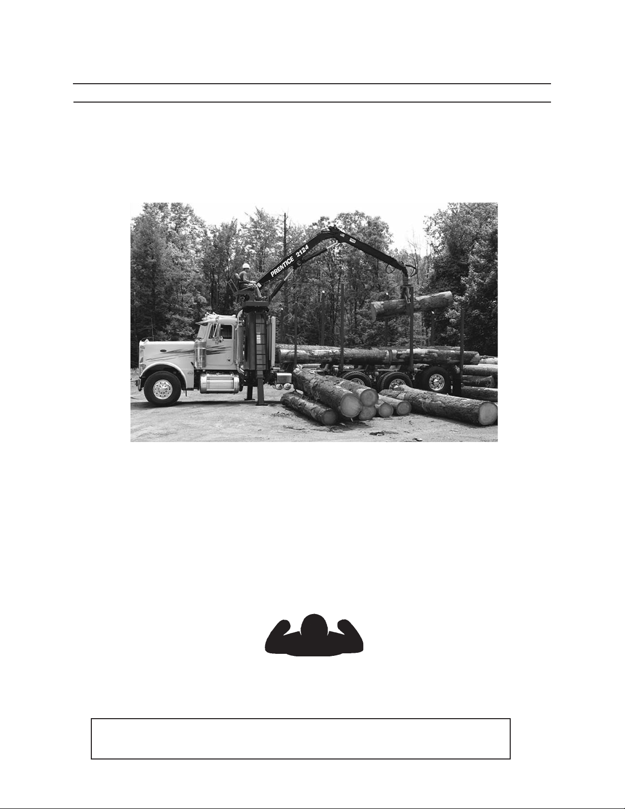
The intended use of this loader is for picking up trees or parts of trees from the ground, or from a vehicle and
piling or stacking them on to a vehicle or to the ground. The loader is normally mounted to a truck body or
trailer (per the manufacturer’s precautions and recommendations). The loader should conduct the movement of the trees or parts of trees with the truck or trailer securely parked on at / level terrain with the A
Frame stabilizers deployed as the upper structure is normally capable of 360 degree swing.
The loader can move trees or parts of trees that are within the object handling capacity of the loader. Ensure
the loader is congured to meet local regulations and use approved attachment handling devices.
To safely operate this machine, follow the instructions in this operator’s manual. Directions in this manual are
referenced from the operator’s seat facing forward (see diagram below).
FORWARD
LEFT RIGHT
BACK
Please help improve this manual. If you nd any mistakes, or if you know of a way to improve procedures, please
let us know. Mail your suggestions or comments to the attention of Technical Publications, Caterpillar Forest
Products, Inc., 3249 South County Road 45, PO Box 568, Owatonna, MN 55060-0568.
This operator’s manual includes information available and current at the time of approval for printing.
Caterpillar Forest Products, Inc., reserves the right to improve its product without giving prior notice or
incurring obligation.
This operator’s manual should be regarded as part of the machine. Suppliers of both new and second hand
machines are advised to retain documentay evidence that this manual was provided with the machine.
Page 6

iV
To The Operator
SAFETY SYMBOLS
SAFETY ALERT SYMBOL
The Safety Alert Symbol means
ATTENTION!
BE ALERT!
YOUR SAFETY IS INVOLVED!
This safety symbol is used to convey important safety messages. To
avoid personal injury and/or property damage, when this symbol is
seen, follow the corresponding safety message.
Understand signal words: DANGER, WARNING, and
CAUTION are used with the SAFETY ALERT SYMBOL.
DANGER IDENTIFIES A HAZARD OR UNSAFE
PRACTICE THAT WILL RESULT IN SEVERE PERSON
AL INJURY OR DEATH.
WARNING identies a hazard or unsafe practice
that could result in severe personal injury or death.
CAUTION identies a hazard or unsafe practice that
could result in personal injury or property damage.
NOTICE identies important installation, operation, or
maintenance information.
Page 7

CONTENTS
v
To The Operator
PRODUCT PROTECTION PLAN .............................................i
Loader ................................................................................i
Attachment ......................................................................... ii
00 TO THE OPERATOR ...........................................................iii
Safety Symbols .................................................................iv
01 GENERAL SAFETY ........................................................11
Safety Alert Symbol .....................................................1-1
Safety Mounting Message .........................................1-1
Operator Preparation ..................................................1-1
Avoid Contact With Stabilizers .................................1-1
Battery Safety .................................................................1-2
Electric Lines ...................................................................1-3
Electric Storm .................................................................1-3
Falling or Swinging Logs ............................................1-4
First Aid Kit ......................................................................1-4
Fire Prevention & Explosion Prevention ...............1-5
Battery & Battery Cables .............................................1-6
Wiring ...........................................................................1-7
Lines, Tubes & Hoses ....................................................1-7
Ether ...........................................................................1-8
Fire Extinguisher ...........................................................1-8
Fluids Under Pressure..................................................1-9
Hand Holds and Steps .................................................1-9
Hand Signals ................................................................ 1-10
Hoses and Fittings ..................................................... 1-10
No Riders on Machine .............................................. 1-11
Operator Safety .......................................................... 1-11
Practice Safe Maintenance .....................................1-12
Pressure Settings .......................................................1-12
Protective Clothing ...................................................1-12
Protective Devices / Equipment ........................... 1-13
Radiator Cap ................................................................ 1-13
Refueling ....................................................................... 1-13
Seat Belt ........................................................................1-14
Unauthorized Welding ............................................. 1-14
Unstable Platform ...................................................... 1-14
02 SAFETY DECALS ...........................................................21
2124 Loader ....................................................................2-1
Do Not Operate Machine ...........................................2-2
Electrocution ..................................................................2-2
Seat Belt ...........................................................................2-2
Transit Lock .....................................................................2-2
Additional Messages ...................................................2-3
Altering A-Frame ...........................................................2-3
Avoid Contact with Stabilizers .................................2-3
Daily Inspection ............................................................2-3
Excessive Pressure ........................................................2-3
Falling or Swining Logs ...............................................2-4
Fluids Under pressure .................................................2-4
Improper Positioning of Loader ..............................2-4
unstable Platform .........................................................2-4
03 COMPONENT TERMINOLOGY .................................31
04 CONTROLS AND INSTRUMENTS ............................41
2124 Operator’s Station ..............................................4-1
Left Joystick ....................................................................4-2
Right Joystick .................................................................4-2
Stabilizer Controls ........................................................4-3
Swing Pedal ....................................................................4-4
Hydraulic Reservoir Sight Gauge ............................4-4
Seat Belt (optional) .......................................................4-4
Transit Lock .....................................................................4-4
Lights (optional) ............................................................4-5
Stop Switch (optional) ................................................4-5
05 PRESTART INSPECTION ............................................51
Pre-Start Checks on the Ground .............................5-1
Pre-Start Checks on the Platform ............................5-2
Fire Prevention ...............................................................5-3
06 OPERATION.....................................................................61
General Guidelines .......................................................6-1
Electrocution Danger ..................................................6-2
Overhead Load Danger ..............................................6-3
Getting on Machine .....................................................6-3
Machine Start Up ..........................................................6-4
Engaging Power Take O (PTO) ...............................6-4
Adjusting Operator’s Seat ..........................................6-5
Seat Belt ...........................................................................6-5
Unlocking Transit Lock ................................................6-6
Warm Up Period ............................................................6-6
Feathering the Controls .............................................6-7
Using the Stabilizers ...............................................6-8–9
Landing Layout ........................................................... 6-10
Picking up Logs .......................................................... 6-10
Grapple Control .......................................................... 6-11
Stopping the Machine ............................................. 6-11
Getting o Machine .................................................. 6-12
Page 8

vI
To The Operator
07 BREAKIN PERIOD ........................................................71
After First 10 Hours ......................................................7-1
After First 100 Hours ....................................................7-2
08 TRANSPORTING ............................................................81
09 LUBRICANTS ...................................................................91
Hydraulic Oil ...................................................................9-1
Grease ...........................................................................9-1
Grease for Swing Drive Bearing
and Swing Drive Motor ............................................9-2
Lubricant for Pinion and
Swing Gear Teeth .......................................................9-2
Cylinder Rod Corrosion Preventive ........................9-2
Storing Lubricants ........................................................9-3
10 MAINTENANCE SAFETY .......................................... 101
Before Maintenance............................................. 10-1–3
Practice Safe Maintenance ................................. 10-1
Hydraulic Safety ..................................................... 10-2
Protective Clothing ............................................... 10-2
Servicing Controls Valves, Cylinders,
Pumps and Motors .............................................10-3
Unauthorized Welding ........................................ 10-3
During Maintenance ............................................ 10-4–5
Diesel Exhaust ........................................................10-4
Fluids Under Pressure .......................................... 10-4
Fuels and Lubricants ............................................10-5
Pinch Points ............................................................. 10-5
After Maintenance ..................................................... 10-6
Disposing of Waste ............................................... 10-6
11 SCHEDULED/PERIODIC MAINTENANCE ............
SERVICES 111
Lubrication and Maintenance Intervals ............... 11-1
Lubrication Notice ....................................................... 11-1
Position Machine for Maintenance ........................ 11-1
As Required .................................................................... 11-2
Daily or Every Ten Hours ............................................ 11-3
Weekly or Every 50 Hours ......................................... 11-4
Monthly or Every 250 Hours ..................................... 11-5
Every Three Months .....................................................11-6
Every Six Months .......................................................... 11-7
Maintenance Details ............................................11-8–24
As Required .................................................................... 11-2
Check Electrical System ............................................. 11-8
Drain and Replace Hydraulic Oil ............................. 11-8
Inspect Safety Decals .................................................. 11-8
Inspect Ladder Structure and Fasteners .............. 11-9
Daily or Every Ten Hours ............................................ 11-3
Perform Daily Visual Inspection ............................11-10
Lube Adaptor Knuckle ..............................................11-10
Lube Main Boom Pivot Pin ......................................11-11
Lube Main Boom Cylinder Base Ends .................11-11
Lube Main Boom Cylinder Rod Ends ...................11-11
Lube Main / Stick Pivot Pin .....................................11-11
Lube Stick Boom Cylinder Base End ....................11-12
Lube Stick Boom Cylinder Rod End .....................11-12
Lube Swing Bearing ..................................................11-12
Lube Pinion Gear ........................................................11-12
Check Hydraulic Oil Level ........................................11-13
Filling Hydraulic Oil Reservoir ................................11-13
Inspect Electrical Components .............................11-14
Inspect Seat Fasteners ..............................................11-14
Weekly or Every 50 Hours ......................................... 11-4
Perform Weekly Inspection ....................................11-15
Inspect Loader Mounting Bolts.............................11-16
Check Boom and Cylinder
Attaching Pins ...........................................................11-16
Check Stabilizer Attaching Pins ............................11-16
Check Hydraulic Oil Res Hdwe ..............................11-16
Check Hydraulic Connections ...............................11-17
Check Hydraulic Oil Reservoir
for Contaminants .....................................................11-17
Inspect Joystick Boots ..............................................11-17
Lubricate Stabilizer Cylinder Rod Ends...............11-18
Lubricate Stabilizer Cylinder Base Ends .............11-18
Monthly or Every 250 Hours ..................................... 11-5
Perform Seat Maintenance ..................................... 11-19
Check Swing Drive Fasteners .................................11-19
Every Three Months or 600 Hours .......................... 11-6
Replace Hydraulic Ret Line Filters ........................ 11-20
Replace Case Drain Filter .........................................11-20
Ck Outer Swg Brng Fastener Torque ...................11-21
Ck Inner Swg Brng Fastener Torque ....................11-21
Lubricate Joystick .......................................................11-21
Every Six Months or 1200 Hours ............................. 11-7
Change Hydraulic Reservoir Oil ............................11-22
Filling Hydraulic Reservoir ......................................11-22
Check / Clean Collector Ring..................................11-23
12 STORAGE ...................................................................... 121
Preparing Machine for Storage ............................. 12-1
Taking Machine Out of Storage ............................ 12-2
13 TROUBLESHOOTING ................................................ 131
2124 Hydraulic System ............................................ 13-1
Cleanliness of Hydraulic Components ............... 13-2
14 SPECIFICATIONS ........................................................141
15 SERIAL NUMBERS ......................................................151
16 MATERIAL SAFETY DATA SHEETS .......................161
Page 9
Safety Section
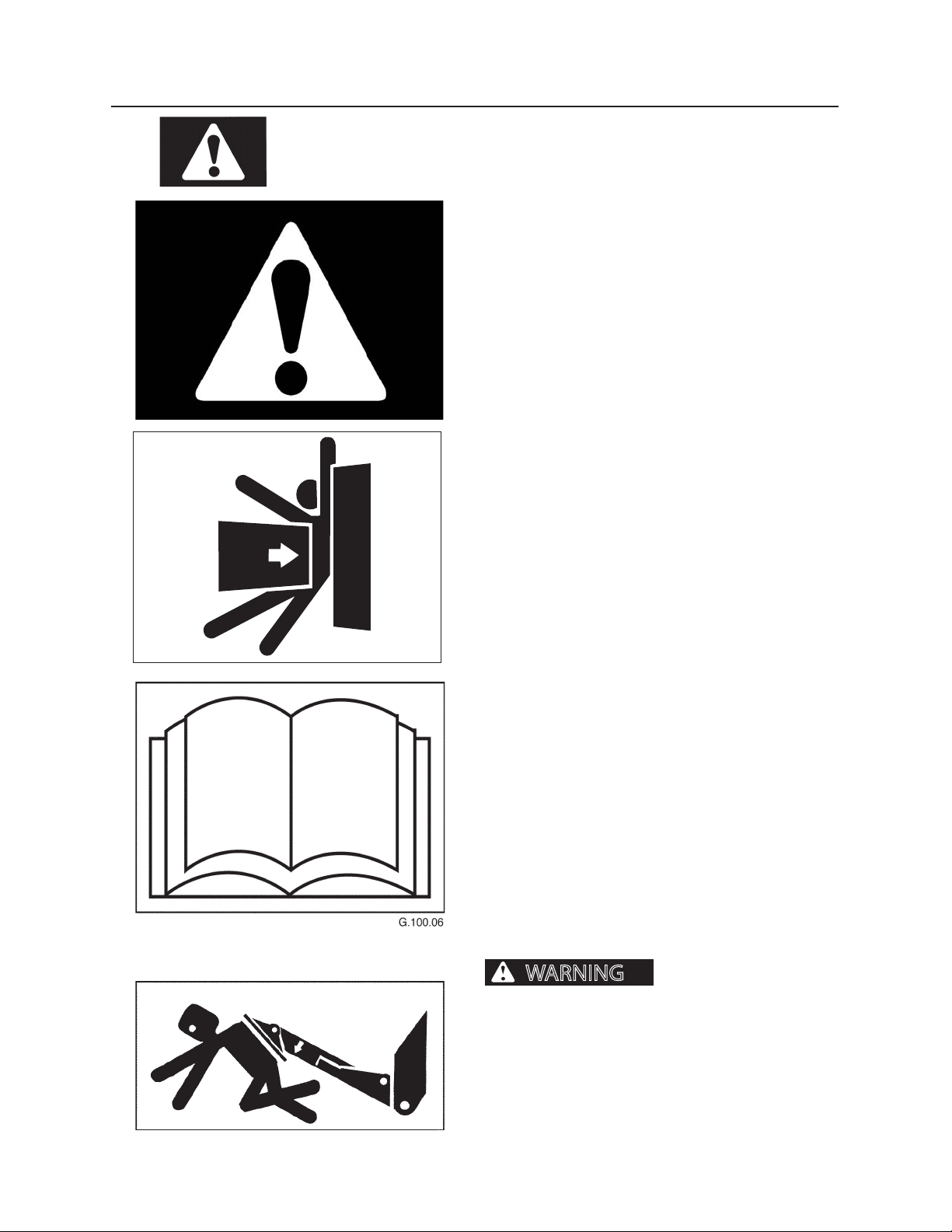
WARNING
Do not operate this machine without reading and understanding the opera-
tor’s manual.
SAFETY ALERT SYMBOL
Read all safety messages.
To avoid personal injury and/or property damage, follow safety messages.
SAFETY MOUNTING MESSAGE
Read all safety messages.
To avoid personal injury and/or property damage, do
not use controls or joysticks as hand holds or footholds
when mounting or dismounting loader. When PTO is
engaged and/or throttle set, controls are active.
11
OPERATOR PREPARATION
Operator must be fully trained, qualied, and authorized to operate this machine. Before operating
this machine, operator must know the location and
purpose of
• controls
• indicator lights
• instruments
• safety and instruction decals
(See Safety Decals Section)
AVOID CONTACT WITH STABILIZERS
Coming into contact with
stabilizers can cause serious personal injury or death.
Clear all personnel from work area before raising or
lowering stabilizers.
Position the machine on rm, level ground, Avoid
slopes and unstable soil conditions that could cause
stabilizers to loose their eectiveness. Clear away
snow, ice and/or debris form beneath wheels and
stabilizer pads.
Page 10
12
WARNING
Safety Section
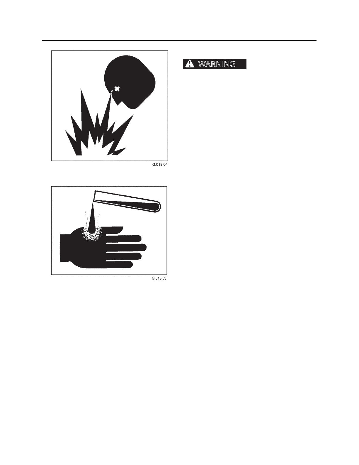
BATTERY SAFETY
Batteries produce explosive
gases that can cause severe personal injury or death.
Battery acid is poisonous and can cause severe burns.
If acid is taken internally, call a physician immediately.
If acid contacts skin or clothing, ush with water immediately. Keep batteries away from children.
Battery posts, terminals, and related accessories contain lead and lead components, chemicals known to
the State of California to cause cancer and reproductive harm. Wash hands after handling.
Keep sparks, ames, and cigarettes away from batteries. Ventilate properly when charging or using batteries in enclosed space. Always shield eyes with goggles
and wear a face shield when working near batteries.
Do not lean over batteries during this operation. Always connect positive (+) to positive (+) and negative
(-) to negative (-). For further instructions, see Jump
Starting Battery in Section 6, Operation. If battery acid
contacts eyes, ush them with water for 15 minutes
and seek immediate medical attention.
Never charge a battery or jump start engine if battery
is frozen. Warm battery to 60°F (16°C) or it may explode. Be sure vent caps are tight. When jump starting
from another machine, be sure machines do not touch.
This machine has a 12-volt starting system. Use equal
voltage for jump starting.
Page 11
13
DANG ER
WARNING
Safety Section
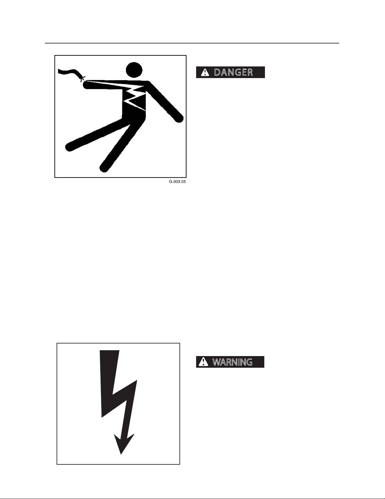
ELECTRIC LINES
SERIOUS INJURY OR
DEATH WILL RESULT FROM CONTACT WITH ELECTRIC
LINES.
Never move any part of machine or load closer
than 10 feet plus twice the line insulator length to
electric lines. A line insulator is what connects an
electric line to an electric pole.
For example, if a line insulator is 6 inches long,
operator must stay at least 10 feet plus twice the
line insulator length (2x6 =12 inches or 1 foot) from
electric line, which means machine must stay at
least 11 feet from the electric line.
If machine touches an electric line, stay inside the
cab. Carefully move machine or load away from
electric line, without pulling the line down.
DO NOT allow anyone else to touch machine while
it is touching an electric line. If machine cannot be
moved away from the electric line without pulling
line down, have someone contact the utility company to disconnect power from line. If this is not
possible, or if machine begins to burn, jump away
from machine to the ground with both feet together, in one smooth jump. Do not run or walk away
from machine. Jump with feet together (“bunny
hop”) away from machine. DO NOT touch machine
and ground at the same time or else electricity in
the line will go through your body. Get away from
machine after jumping.
Notify the utility company immediately. DO NOT
let anyone near the machine while it is touching an
electric line.
ELECTRICAL STORM
Electrical storms (lightning)
can cause severe personal injury or death.
When lightning is striking in the vicinity of the
machine, the operator should NEVER attempt the
following procedures:
Mount the machine
Dismount the machine
If you are in the operator’s station during an electrical
storm, stay in the operator’s station. If you are on the
ground during an electrical storm, stay away from the
vicinity of the machine.
Page 12
14
CAUTION
WARNING
Safety Section
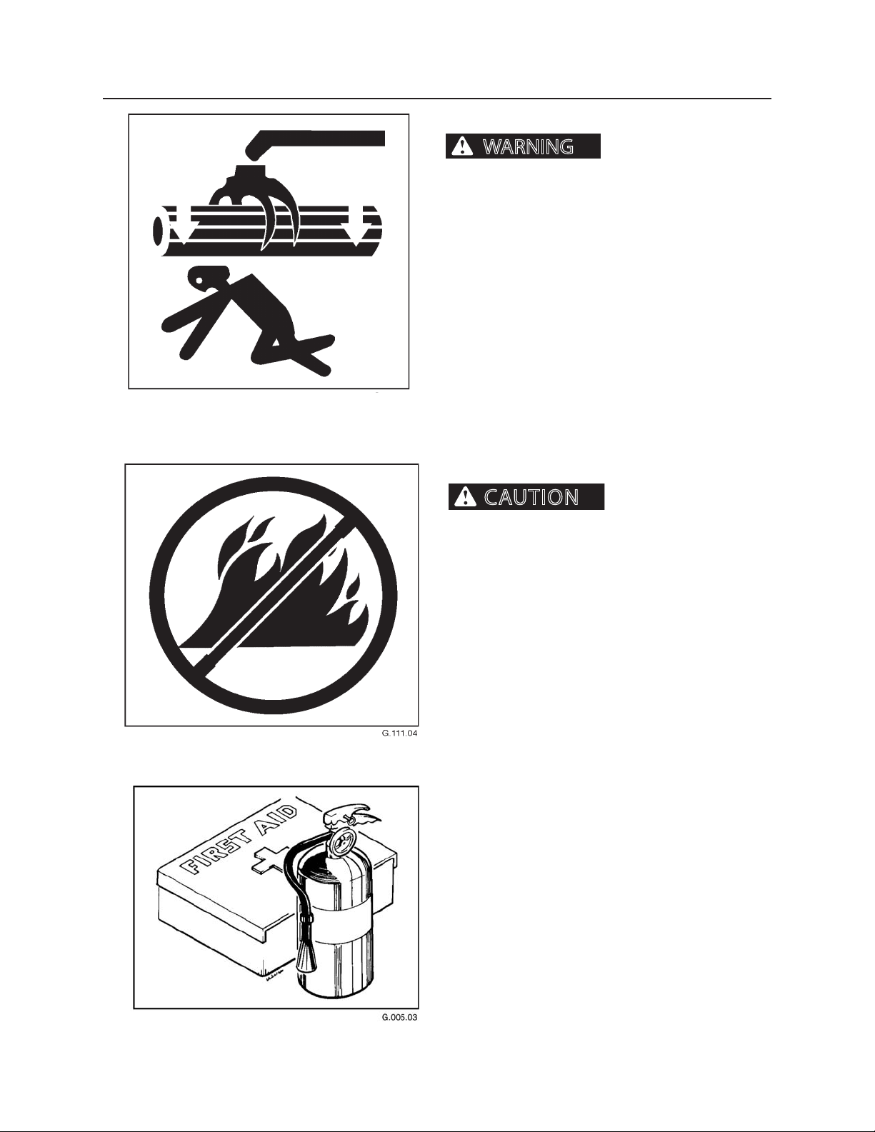
FALLING OR SWINGING LOGS
Falling or swinging logs,
booms, or attachments can cause severe personal
injury or death.
Never operate the boom, attachment or load over or
near personnel.
FIRST AID KIT
injury and/or machine damage.
Much of the material found in forestry operations is
highly ammable, including limbs, bark, leaves, saw
dust, small wood chips and pine needles. When the
forestry debris is soaked in fuel or lubricants, the risk
of re is greatly increased. Doing a daily inspection
before every shift, or more often based on the work activity and build-up of debris, is the best way to prevent
a machine re. Frequent inspections and thorough
machine cleaning are critical when engaged in forestry
operations, and even minor leaks or electrical malfunctions should be repaired as soon as possible.
Keep machine clean. Highly ammable debris such
as leaves, twigs, saw dust, small wood chips and pine
needles can collect on and in equipment used in forestry operations. If allowed to accumulate, the debris
can rapidly become the fuel component of a machine
re. Clean all accumulations of forest debris in the engine compartment or around other hot areas and hot
parts on the machine at the completion of each work
shift or more frequent when working in conditions
where large amounts of forest debris are present.
Fires can cause personal
Repair all hydraulic and fuel leaks immediately. Do not
operate machine with hydraulic or fuel leaks.
Fire prevention beats re ghting. Remove debris from
all compartments after every 8 hours of operation, or
more often, if warranted by working conditions.
Install a rst-aid kit in the cab.
Properly maintain rst-aid kit and re extinguisher. Follow instructions provided with them.
Page 13

15
Safety Section
FIRE PREVENTION AND EXPLOSION PRE
VENTION
GENERAL
All fuels, most lubricants, and some coolant mixtures are ammable.
To minimize the risk of re or explosion, Caterpillar
recommends the following actions.
Always perform a Walk-Around Inspection, which
may help you identify a re hazard. Do not operate
a machine when a re hazard exists. Contact your
Caterpillar dealer for service.
Understand the use of the primary exit and alternative exit on the machine. Refer to Operation and
Maintenance Manual, “Alternative Exit”.
Do not operate a machine with a uid leak. Repair
leaks and clean up uids before resuming machine
operation. Fluids that are leaking or spilled onto
hot surfaces or onto electrical components can
cause a re. A re may cause personal injury or
death.
Remove ammable material such as leaves, twigs,
papers, trash, etc. These items may accumulate
in the engine compartment or around other hot
areas and hot parts on the machine.
of each work shift or more frequently when working
in conditions where large amounts of forest debris are
present.
Keep the access doors to major machine compartments closed and access doors in working condition in
order to permit the use of re suppression equipment,
in case a re should occur.
Clean all accumulations of ammable materials such
as fuel, oil and debris from the machine.
Do not operate the machine near any ame.
Keep shields in place. Exhaust shields (if equipped)
protect hot exhaust components from oil spray or fuel
spray in case of a break in a line, in a hose, or in a seal.
Exhaust shields must be installed correctly.
Do not weld or ame cut on tanks or lines that contain
ammable uids or ammable material. Empty and
purge the lines and tanks. Then clean the lines and
tanks with a nonammable solvent prior to welding or
ame cutting. Ensure that the components are properly grounded in order to avoid unwanted arcs.
Dust that is generated from repairing nonmetallic
hoods or fenders may be ammable and/or explosive.
Repair such components in a well ventilated area away
from open ames or sparks. Use suitable Personal
Protection Equipment (PPE).
Inspect all lines and hoses for wear or deterioration.
Replace damaged lines and hoses. The lines and the
hoses should have adequate support and secure
clamps. Tighten all connections to the recommended
torque. Damage to the protective cover or insulation
may provide fuel for res.
Much of the material found in forestry operations
is highly ammable, including limbs, bark, leaves,
saw dust, small wood chips and pine needles.
When the forestry debris is soaked with fuel or lubricants, the risk of re is greatly increased. Doing
a daily inspection before every shift, or more often
based on the work activity and build-up of debris,
is the best way to prevent a machine re. Frequent
inspections and thorough machine cleaning are
critical when engaged in forestry operations, and
even minor leaks or electrical malfunctions should
be repaired as soon as possible.
Highly ammable debris such as leaves, twigs, saw
dust, small wood chips and pine needles can collect on and in equipment used in forestry operations. If allowed to accumulate, the debris can
rapidly become the fuel component of a machine
re. Clean all accumulations of forest debris in the
engine compartment or around other hot areas
and hot parts on the machine at the completion
Page 14
16
Safety Section
Store fuels and lubricants in properly marked containers away from unauthorized personnel. Store oily rags
and ammable materials in protective containers. Do
not smoke in areas that are used for storing ammable
materials.
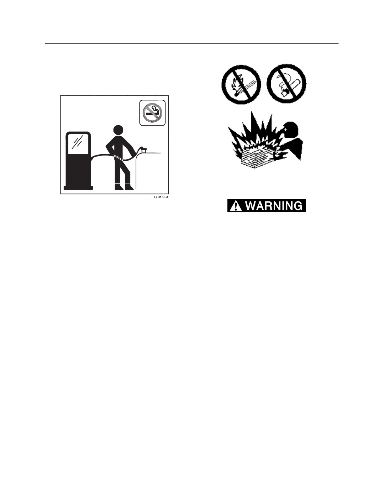
Use caution when you are fueling a machine. Do not
smoke while you are fueling a machine. Do not fuel
a machine near open ames or sparks. Always stop
the engine before fueling. Fill the fuel tank outdoors.
Properly clean areas of spillage.
Follow practices for safe fueling that are described in
the “Operation” section of the Operation and Maintenance Manual section and follow local regulations.
Never store ammable uids in the operator compartment of the machine.
BATTERY AND BATTERY CABLES
Caterpillar recommends the following in order to
minimize the risk of re or an explosion related to the
battery.
Do not operate a machine if battery cables or related
parts show signs of wear or damage. Contact your
Caterpillar dealer for service.
Follow safe procedures for engine starting with jump
start cables. Improper jumper cable connections can
cause an explosion that may result in injury. Refer to
Operation and Maintenance Manual, “Engine Starting
with Jump Start Cables” for specic instructions.
Do not charge a frozen battery. This may cause an
explosion.
Gases from a battery can explode. Keep any open
ames or sparks away from the top of a battery. Do not
smoke in battery charging areas.
Never check the battery charge by placing a metal
object across the terminal posts. Use a voltmeter or a
hydrometer.
Daily inspect battery cables that are in visible areas.
Identify cables, clips, straps, and other restraints for
damage. Replace these items if necessary. Look for
signs of the following, which can occur over time due
to use and environmental factors:
• Fraying
• Abrasion
• Cracking
• Discoloration
• Cuts on the insulation of the cable
• Fouling
• Corroded terminals, damaged terminals, and loose
terminals
Page 15
17
Safety Section
Replace damaged battery cable(s) and replace any
related parts. Eliminate any fouling, which may have
caused insulation failure or related component damage or wear. Ensure that all components are reinstalled
correctly.
An exposed wire on the battery cable may cause a
short to ground if the exposed area comes into contact with a grounded surface. A battery cable short
produces heat from the battery current, which may be
a re hazard.
An exposed wire on the ground cable between the
battery and the disconnect switch may cause the
disconnect switch to be bypassed if the exposed area
comes into contact with a grounded surface. This may
result in an unsafe condition for servicing the machine.
Repair components or replace components before
servicing the machine.
Fire on a machine can result in personal injury or
death. Exposed battery cables that come into contact
with a grounded connection can result in res. Replace
cables and related parts that show signs of wear or
damage. Contact your Caterpillar dealer.
LINES, TUBES AND HOSES
Do not bend high pressure lines. Do not strike high
pressure lines. Do not install any lines that are bent or
damaged. Use the appropriate backup wrenches in
order to tighten all connections to the recommended
torque.
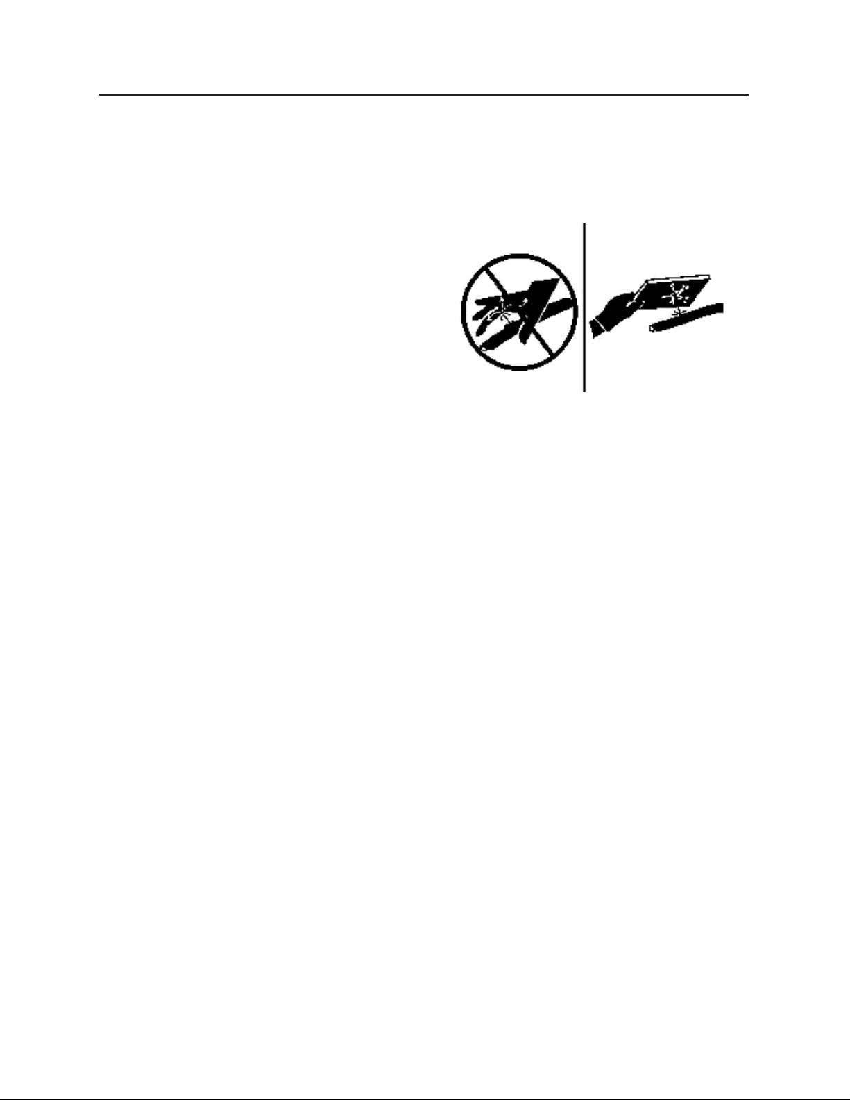
Check lines, tubes and hoses carefully. Wear Personal
Protection Equipment (PPE) in order to check for leaks.
Always use a board or cardboard when you check for a
leak. Leaking uid that is under pressure can penetrate
body tissue. Fluid penetration can cause serious injury
and possible death. A pin hole leak can cause severe
injury. If uid is injected into your skin, you must get
treatment immediately. Seek treatment from a doctor
that is familiar with this type of injury.
WIRING
Check electrical wires daily. If any of the following
conditions exist, replace parts before you operate the
machine.
• Fraying
• Signs of abrasion or wear
• Cracking
• Discoloration
• Cuts on insulation
• Other damage
Make sure that all clamps, guards, clips, and straps are
reinstalled correctly. This will help to prevent vibration,
rubbing against other parts, and excessive heat during
machine operation.
Attaching electrical wiring to hoses and tubes that
contain ammable uids or combustible uids should
be avoided.
Consult your Caterpillar dealer for repair or for replacement parts.
Replace the aected parts if any of the following conditions are present:
• End ttings are damaged or leaking.
• Outer coverings are chafed or cut.
• Wires are exposed.
• Outer coverings are swelling or ballooning.
• Flexible parts of the hoses are kinked.
• Outer covers have exposed embedded armoring.
• End ttings are displaced.
Make sure that all clamps, guards, and heat shields are
installed correctly. During machine operation, this will
help to prevent vibration, rubbing against other parts,
excessive heat, and failure of lines, tubes and hoses.
Do not operate a machine when a re hazard exists.
Repair any lines that are corroded, loose or damaged.
Leaks may provide fuel for res. Consult your Caterpillar dealer for repair or for replacement parts. Use genuine Caterpillar parts or the equivalent, for capabilities
of both the pressure limit and temperature limit.
Keep wiring and electrical connections free of debris.
Page 16

18
Safety Section
ETHER
Ether (if equipped) is commonly used in cold weather
applications. Ether is ammable and poisonous.
Follow the correct cold engine starting procedures.
Refer to the section in the Operation and Maintenance
Manual with the label “Engine Starting”.
Do not spray ether into an engine if the machine is
equipped with a thermal starting aid for cold weather
starting.
Use ether in well ventilated areas. Do not smoke while
you are replacing an ether cylinder or while you are
using an ether spray.
Do not store ether cylinders in living areas or in the operator compartment of a machine. Do not store ether
cylinders in direct sunlight or in temperatures above
49° C (120.2° F). Keep ether cylinders away from open
ames or sparks.
Dispose of used ether cylinders properly. Do not puncture an ether cylinder. Keep ether cylinders away from
unauthorized personnel.
FIRE EXTINGUISHER
As an additional safety measure, keep a re extinguisher on the machine.
Be familiar with the operation of the re extinguisher.
Inspect the re extinguisher and service the re extinguisher regularly. Follow the recommendations on the
instruction plate.
Consider installation of an aftermarket Fire Suppression System, if the application and working conditions
warrant the installation.
Page 17
19
WARNING
WARNING
Safety Section
FLUIDS UNDER PRESSURE
Fluids escaping under pressure can penetrate skin and cause severe personal
injury or death. Wear eye and personal protection
equipment (PPE)!
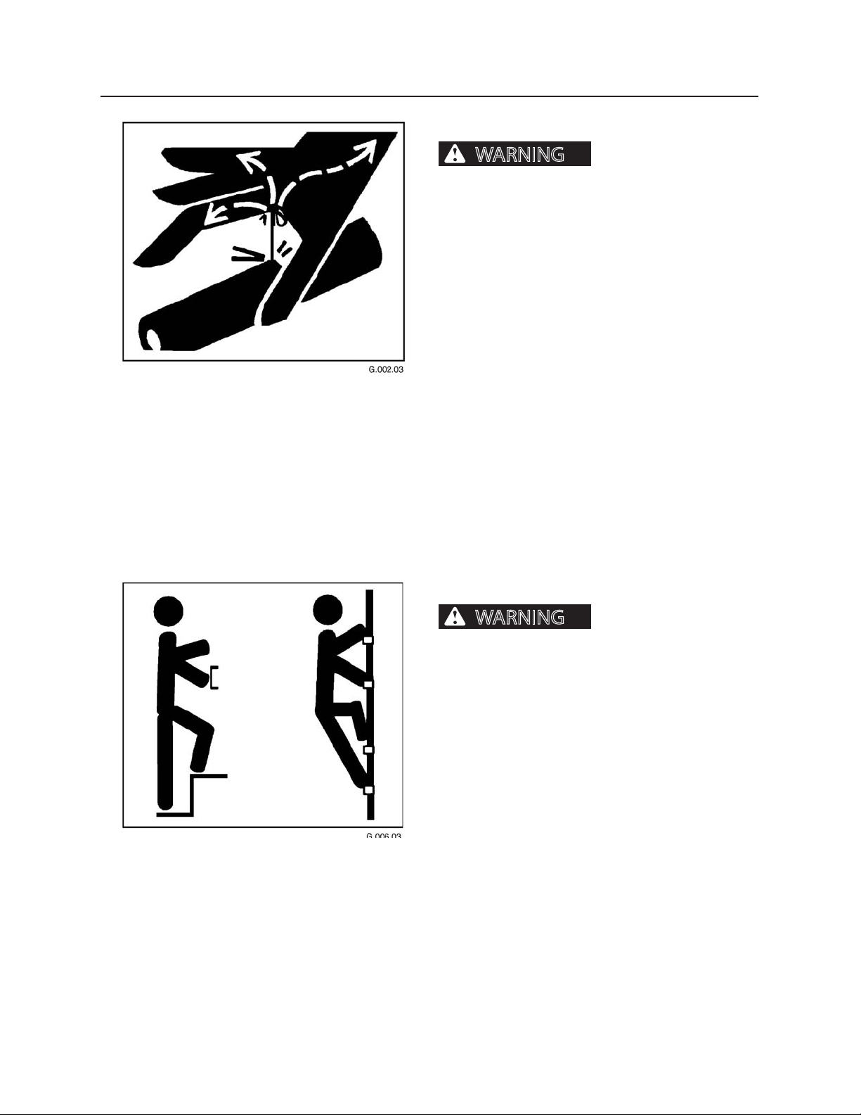
Always use a board or cardboard when checking oil
hoses, lines, and ttings for leaks, cracks, or defects.
Be sure all clamps are in their proper position and
torqued as required and specied. Be sure hoses are
not twisted or touching parts.
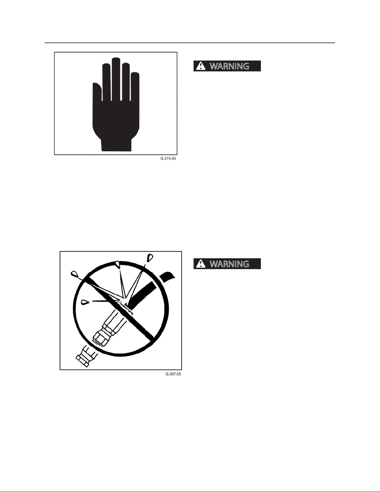
DO NOT use hands to search for leaks. Escaping uids
can penetrate skin and enter the bloodstream. Before
disconnecting lines, relieve all pressure.
DO NOT apply pressure to a damaged line, hose, or
tting.
If ANY uid is injected into the skin, seek medical attention immediately. A serious infection or reaction
can result without proper medical treatment.
HAND HOLDS AND STEPS
Slips and falls can cause
severe personal injury or death.
Use provided hand holds and steps while maintaining at least 3 points of support (1 foot and 2 hands or
2 feet and 1 hand) when getting on and o machine.
Face machine when getting on and o of it.
Never use controls as hand holds. Never use steering
wheel as a hand hold. Moving the steering wheel from
its center position will COMPLETELY turn machine right
or left.
DO NOT mount machine if hand rails or steps are broken or missing. Get them repaired rst.
DO NOT jump on or o machine unless it has touched
a live electrical wire and it must be exited.
Ensure rm foot position when getting on and o
machine. Be careful of slippery conditions on platform, steps, and hand holds when getting on and o
machine.
Remove oil, grease, mud, ice, etc. before mounting or
dismounting machine.
To prevent slips and falls, replace skid-resistant material if it is worn, damaged or missing.
Page 18
110
WARNING
WARNING
Safety Section
HAND SIGNALS
Accidents can cause severe
personal injury or death.
Know and use the hand signals required for particular
jobs.
Know who has the responsibility for signaling.
HOSES AND FITTINGS
Mismatched brands or
types of hoses and ttings can blow apart and cause
severe personal injury or death.
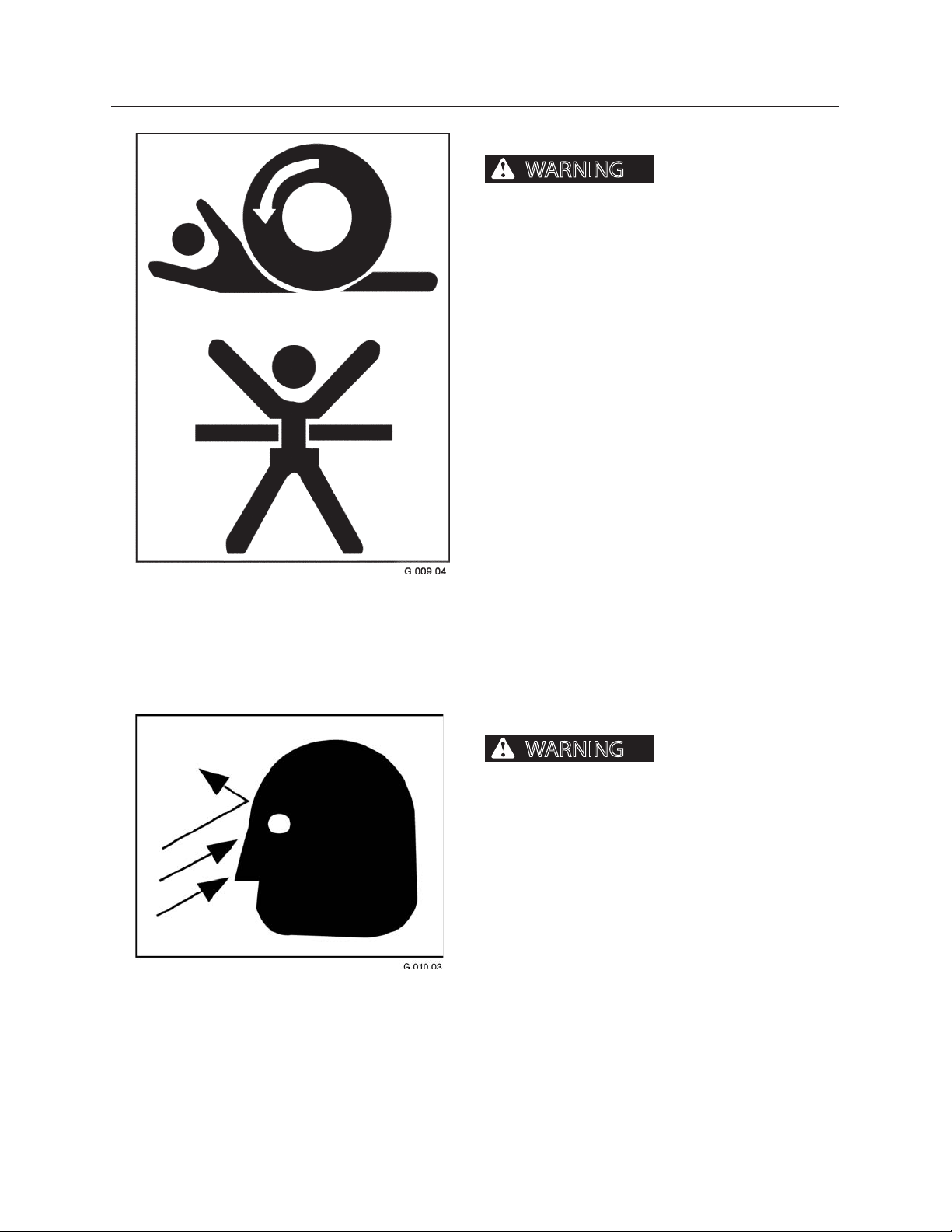
DO NOT interchange brands or types of hoses
and ttings.
DO NOT install a tting from one manufacturer on a
hose from a dierent manufacturer.
DO NOT install crimp ttings on hoses meant for reusable ttings.
Wear eye and personal protection equipment (PPE)!
Always use a board or cardboard when checking oil
hoses, lines, and ttings periodically for leaks, cracks or
defects. Be sure all clamps are in their proper position
and torqued as required and specied. Be sure hoses
are not twisted or touching parts.
Page 19
111
WARNING
WARNING
Safety Section
NO RIDERS ON MACHINE
Machine riders can fall from
machine or be injured by movement of machinery,
causing severe personal injury or death.
Do not allow riders on any machine that is operating
or moving.
OPERATOR SAFETY
Flying debris, tree limbs,
and/or other material can cause severe personal injury
or death.
When operating machine:
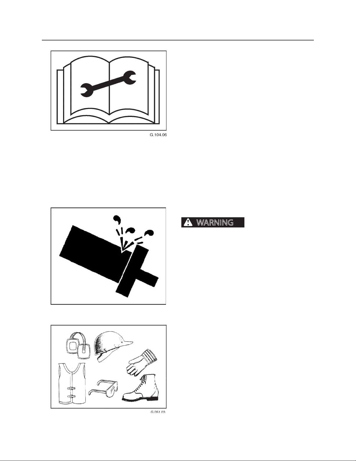
1. Cab door must stay closed.
2. Window material and/or cab guarding MUST be in
place.
3. All cab openings (front, side, and rear) MUST be
covered with window material (no glass) and/or
protective screen.
4. Window guarding MUST be locked
in place.
Page 20
112
WARNING
Safety Section
PRACTICE SAFE MAINTENANCE
Understand service procedures before performing
maintenance. When performing maintenance, keep
area around machine clean and dry.
DO NOT service machine while it is moving. Keep away
from power-driven parts. Lower attachment to the
ground. Disengage power. Shut engine down. Move
controls in all directions to relieve hydraulic pressure.
Remove key from ignition. Allow machine to cool
down.
Support all raised equipment.
Keep all machine parts in good condition, and be sure
parts are properly installed. Repair damage immediately. Repair all hydraulic and fuel leaks immediately.
Replace worn or broken parts. Remove any buildup of
grease, oil, or debris.
Disconnect battery ground cable (-) before adjusting
the electrical system.
PRESSURE SETTINGS
Excessive hydraulic pressure
can cause component or structural failure, which may
result in severe personal injury or death.
Wear eye and personal protection equipment (PPE)!
DO NOT exceed factory-adjusted pressure settings.
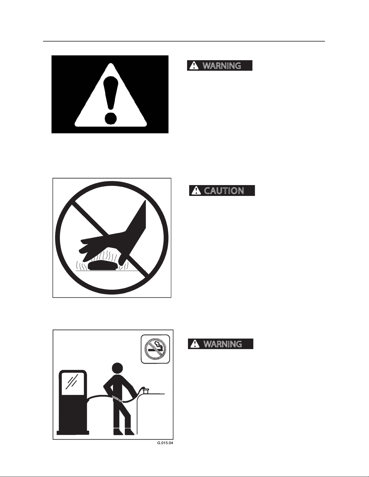
PROTECTIVE CLOTHING
Wear OSHA or local governing body-approved protective clothing when working on or near this machine,
such as
• ear protection • hard hat
• gloves • orange vest
• goggles • steel-toed shoes
Wear snug, protective clothing that is belted where
required.
Remove jewelry before working on or near this machine.
Page 21
113
CAUTION
WARNING
WARNING
Safety Section
PROTECTIVE DEVICES/EQUIPMENT
Misuse, interference and ignorance of protective equipment or devices can cause
severe personal injury or death.
Alarms, re prevention equipment, ROPS/FOPS/OPS,
and other safety equipment is installed on machine for
your protection.
Never ignore, disconnect, disable or modify protection
equipment in any manner.
RADIATOR CAP
tem can cause scalding burns.
Wear eye and personal protection equipment (PPE)!
Do not remove radiator cap unless engine is cool.
Allow system to cool. Remove cap slowly to relieve
pressure before removing completely.
REFUELING
cause severe personal injury or death.
Handle fuel with care. It is highly ammable.
Pressurized cooling sys-
Fires and explosions can
DO NOT refuel machine while smoking or when near
open ame or sparks.
Always stop engine before refueling. Fill fuel tank outdoors. Prevent res by keeping machine clean of trash,
grease, and debris. Always clean up spilled fuel.
Page 22
114
WARNING
NOTICE
G.020.05
WARNING
WARNING
Safety Section
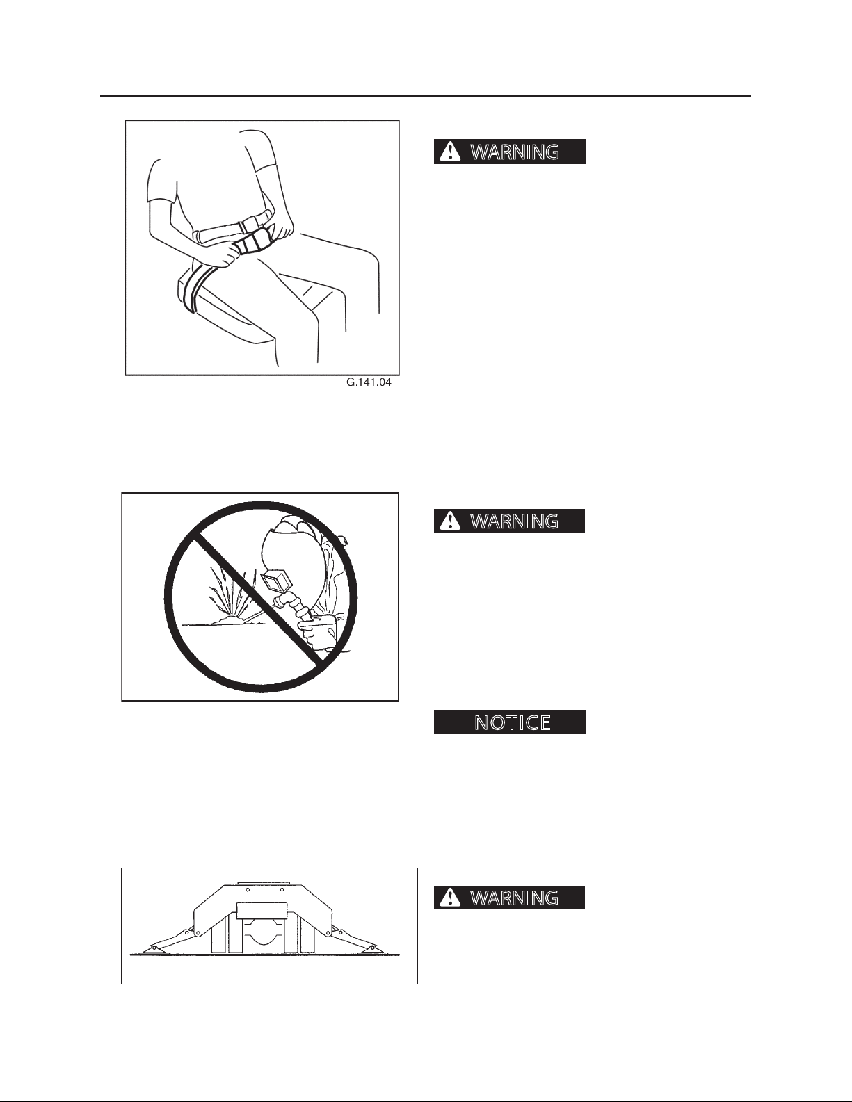
SEAT BELT OPTIONAL
A roll over or sudden stop
can cause severe personal injury or death.
To reduce risk of personal injury resulting from a roll
over or sudden stop, always wear a seat belt fastened
snugly when operating this machine.
This machine can change directions rapidly. It can start
and stop quickly. See Operation Section in this manual
for instructions on properly using the seat belt.
UNAUTHORIZED WELDING
Unauthorized welding can
cause structural failure and/or severe personal injury
or death.
DO NOT weld on any structural member.
Any unauthorized welding or repair will void
the warranty.
Once authorized, be sure to turn battery disconnect
master switch OFF and place welding ground (stinger)
as close to weld site as possible. Do not allow weld current to pass through bearings or pivot points.
Unauthorized welding can
cause damage to the electrical system.
UNSTABLE PLATFORM
Unstable platform can
cause severe personal injury or death.
Lower all stabilizers before operating machine.
Page 23
21
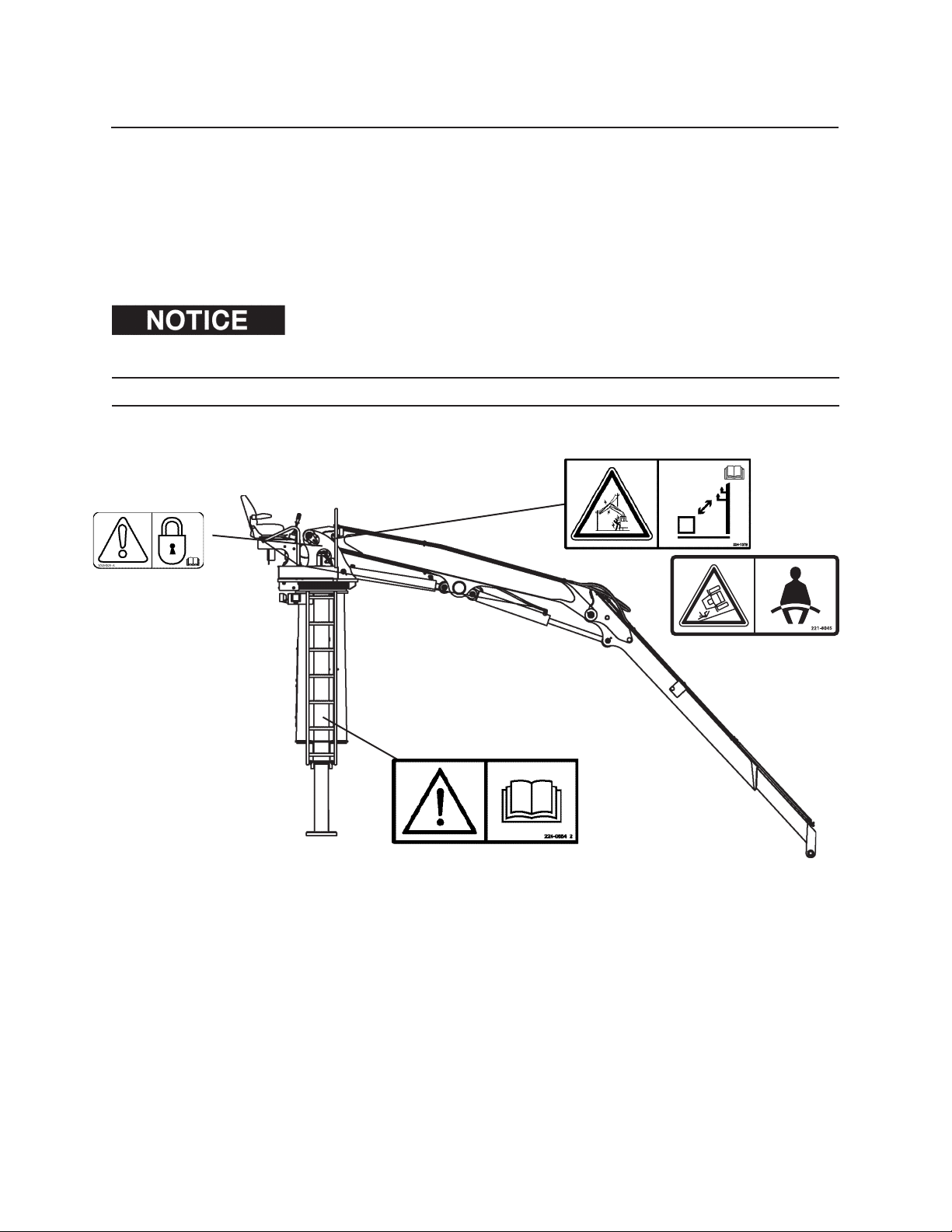
Safety Decals
The following safety decals are located in position on the machine as continual reminders of HAZARDS. Serious
injury or property damages can occur if safety instructions are not followed.
Keep all safety decals clean and readable. Use a soft cloth, water, and soap to clean decals if they are too dirty to
read. DO NOT clean safety decals with solvent. Solvent can damage them.
Replace safety decals immediately if they are damaged, missing, or hard to read. Contact an authorized dealer for
replacement safety decals. Authorized dealers will provide free replacement safety decals if given a valid serial
number for this machine.
When replacing a part containing a safety decal, apply a new safety decal to the replace-
ment part. Before putting a new decal on the machine or part, be sure the surface where the decal will be mounted is
clean and dry.
2124 LOADER
Page 24
22
WARNING
WARNING
WARNING
Safety Decals
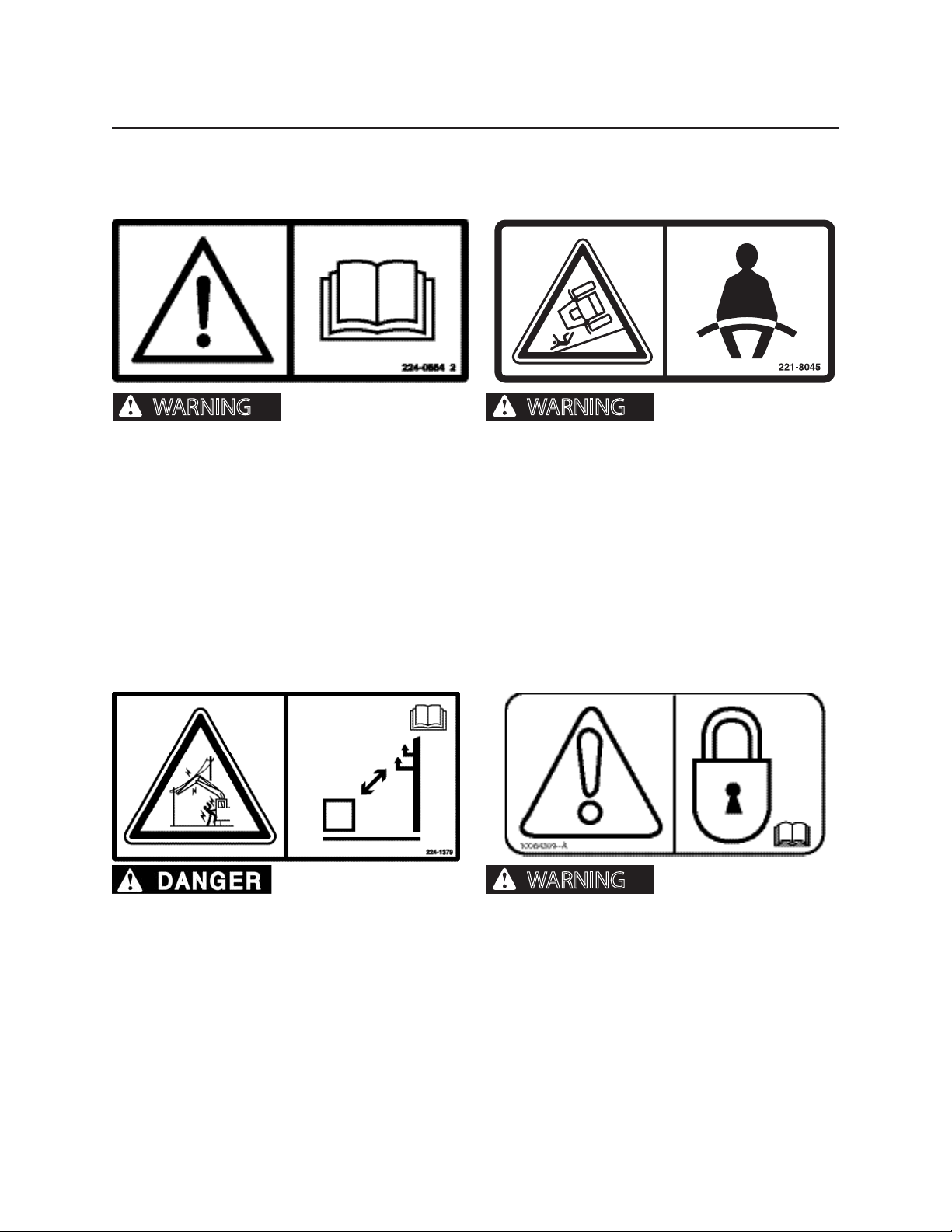
Do Not Operate Machine
This warning is located on the surface of the seat riser.
Do not operate or work on
this machine unless you have read and understand
the instructions and warnings in the Operation and
Maintenance manuals. Failure to follow the instructions or head the warnings could result in injury or
death. Contact your authorized dealer fro replacement manuals. Proper care is your responsibility.
Seat Belt (optional)
This warning is located on the surface of the boom (visible from the operator’s seat).
A seat belt should be
worn at all times during machine operation to
prevent serious injury or death in the event of an
accident or machine overturn. Failure to wear a seal
belt during machine operation may result in serious injury or death.
Electrocution
This warning is located on the surface of the boom (visible from the operator’s seat).
Electrocution Hazard!
Keep the machine and attachments a safe distance
from electrical power. Stay clear 3 m (10ft) plus
twice the line insulator length. Read and understand the instructions and warnings in the Operation and Maintenance Manual. Failure to follow the
instructions and warnings will cause serious injury
or death.
Transit Lock
This warning is located on the operator platform next
to the Transit Lock.
Engage Transit Lock before transporting loader. Failure to engage transit
lock can cause severe personal injury or death.
Page 25
23
WARNING
WARNING
WARNING
WARNING
Safety Decals
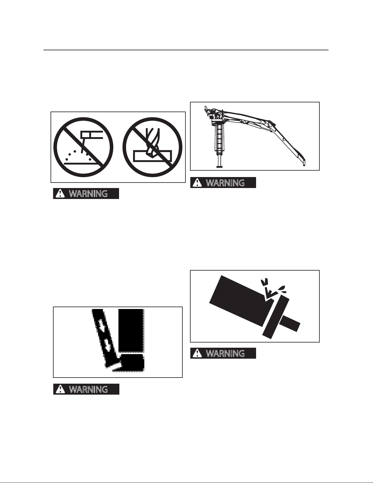
Additional Safety Messages:
Altering A-Frame
DO NOT ALTER AFRAME STRUCTURE. DO NOT
WELD OR MACHINE AFRAME STRUCTURE. IF A
FRAME IS DAMAGED, CONTACT AN AUTHORIZED
DEALER.
Structural damage, an
overturn, modication, alteration, or improper
repair can impair this structure’s protection
capability thereby voiding this certication. Do
not weld on or drill holes in the structure. This
will void the certication. Consult an authorized
dealer to determine this structure’s limitations
without voiding its certication.
Daily Inspection
PERFORM A DAILY INSPECTION OF THE FOLLOWING COMPONENTS: STRUCTURES, BOOMS, CYLINDERS, TURNTABLE, SWING BEARING, LOAD BEARING ITEMS & ALL MOUNTINGS.
Failure to perform a
daily inspection of the loader could result in
severe personal injury or machine damage.
Excessive Pressure
DO NOT EXCEED FACTORY–ADJUSTED RELIEF
PRESSURE SETTINGS.
Avoid Contact with Stabilizers
CLEAR ALL PERSONNEL FROM WORK AREA BEFORE
LOWERING STABILIZERS.
Contact with stabilizers could result in severe personal injury or
property damage.
Excessive hydraulic
pressure can cause component or structural
failure causing severe personal injury or death.
Page 26
24
WARNING
WARNING
WARNING
WARNING
Safety Decals
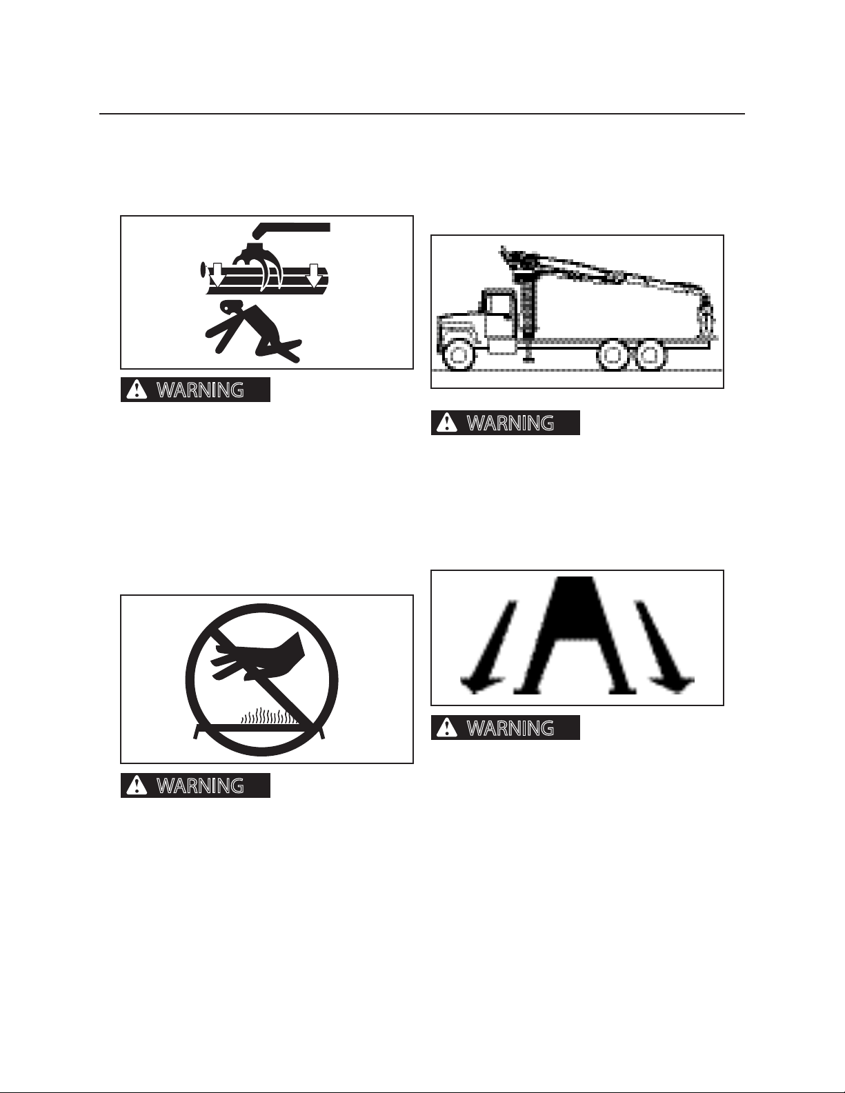
Falling or Swinging Logs
NEVER OPERATE THE BOOM OR LOAD OVER OR
NEAR PERSONNEL.
Do not operate the
boom or load over or near personnel. Falling or
swinging logs can cause severe personal injury
or death.
Fluid Under Pressure
REFER TO OPERATOR’S MANUAL FOR MAINTENANCE INSTRUCTIONS.
Improper Positioning of Loader
DO NOT TRANSPORT LOADER WITHOUT PLACING
ALL COMPONENTS IN TRANSPORT POSITION AND
ENGAGING TRANSIT/SWING LOCK.
DImproper positioning of loader can cause severe personal injury
or death.
Unstable Platform
LOWER ALL STABILIZERS BEFORE OPERATING.
Unstable platform can
cause severe personal injury or machine damage.
Fluid escaping under
pressure can penetrate skin and cause severe
personal injury or death.
Page 27
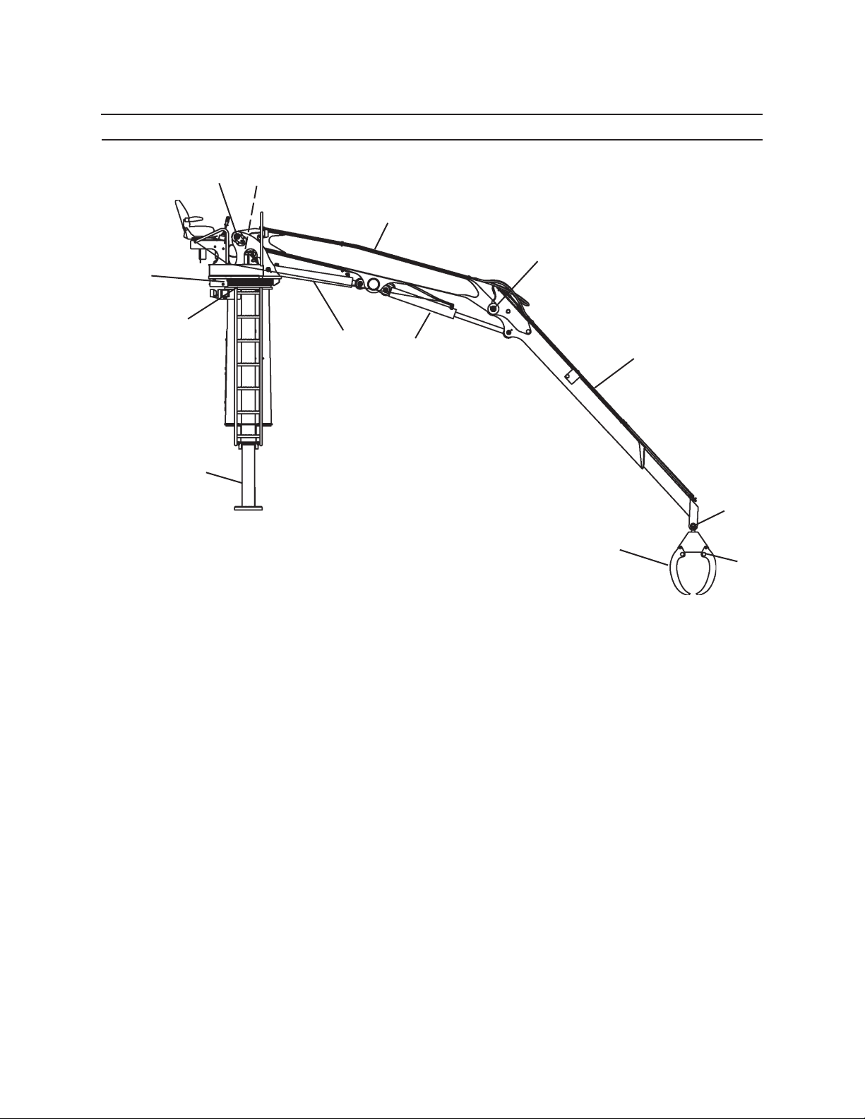
2124 LOADER
31
Component Terminology
13
9
3
6
10
2
5
7
8
1
12
4
11
1. Stabilizer Leg
2. Swing Bearing
3. Swing Drive
4. Grapple
5. Main Boom Cylinder
6. Main Boom
7. Stick Boom Cylinder
8. Stick Boom
9. Main Boom Pivot Pin
10. Stick Boom Pivot Pin
11. Grapple Pivot Pin
12. Adapter Knuckle
13. Turntable Assembly
Page 28

32
Component Terminology
Page 29
41
Controls & Instruments
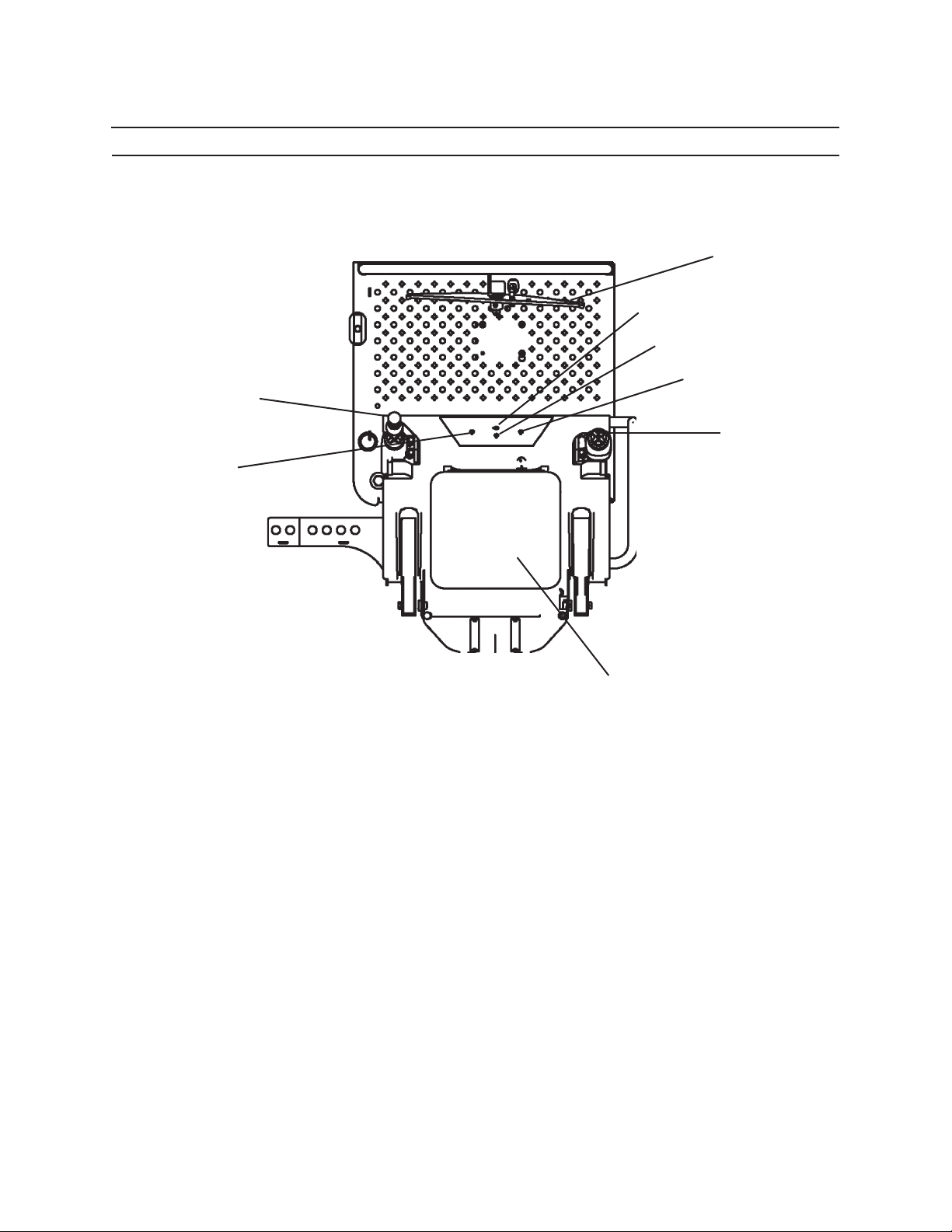
2124 OPERATOR’S STATION
2
7
8
6
3
4
5
1
1. Operator’s Seat
2. Swing Pedal
3. Left Joystick: Controls grapple open close and main
boom
4. Right Joystick: controls grapple rotate, stick boom and
telescopic boom (optional)
5. Left Stabilizer Control Switch
6. Right Stabilizer Control Switch
7. Light Switch (optional)
8. Stop Switch (optional)
Page 30
42
DOWN
CCW
CW
UP
S
T
I
C
K
B
O
O
M
GRAPPLE ROTATE
OPEN
CLOSE
M
A
I
N
B
O
O
M
GRAPPLE
DOWN
UP
Controls & Instruments
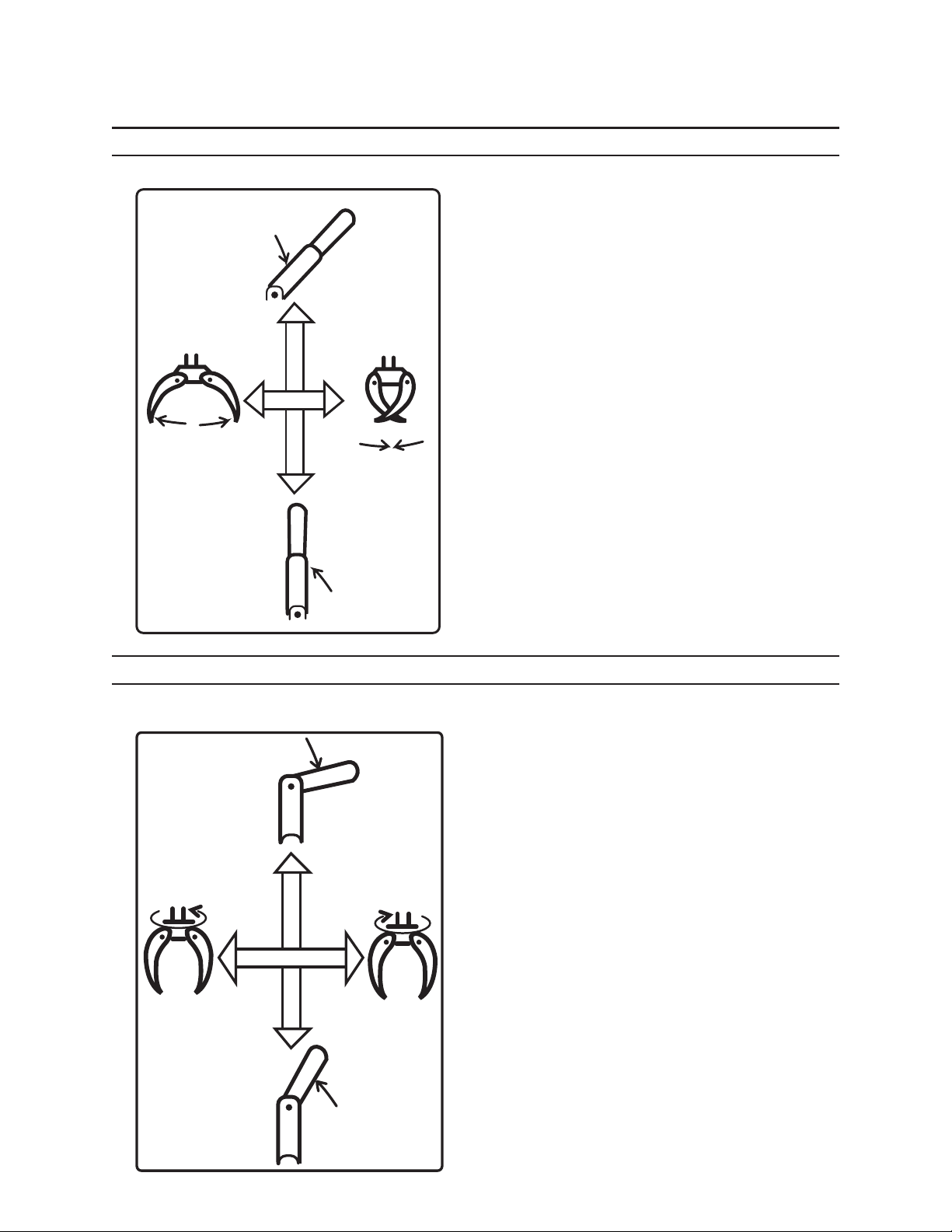
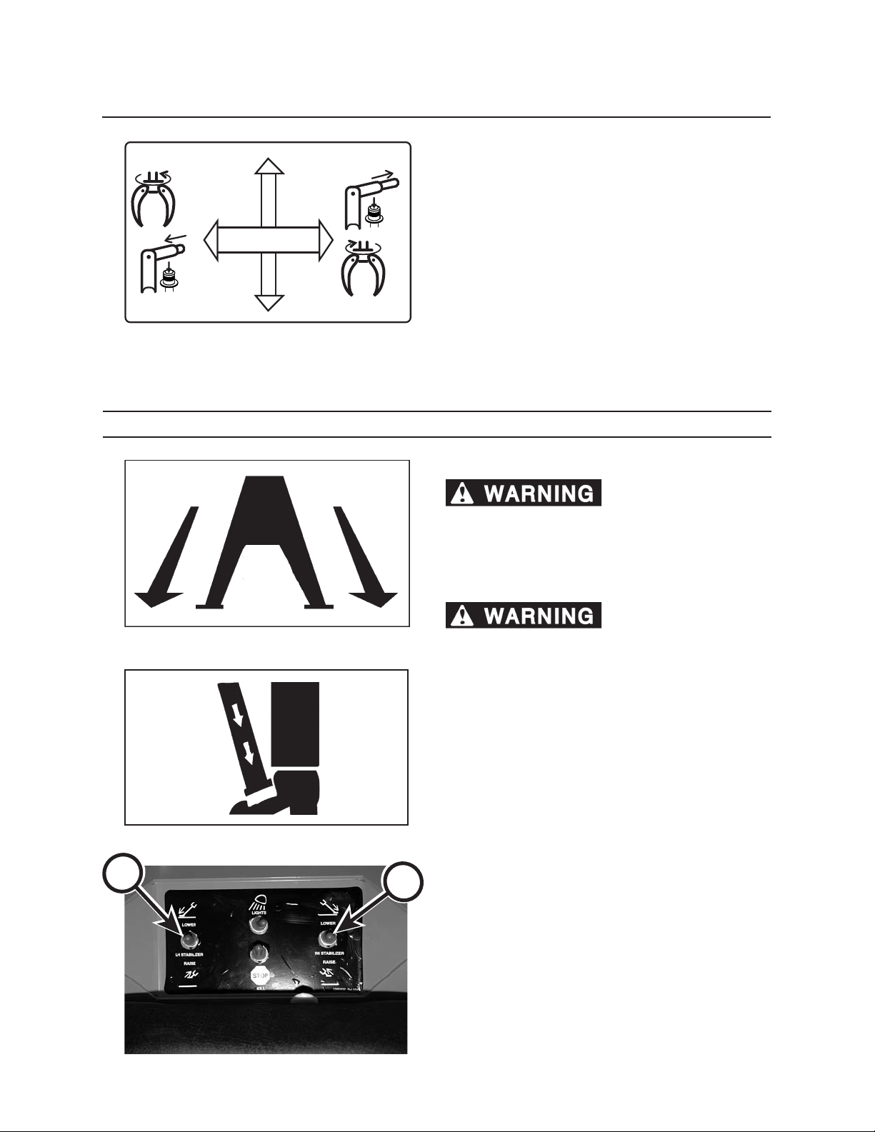
LEFT JOYSTICK CONTROL
USING THE MAIN BOOM
Push left joystick back to raise boom.
Push left joystick forward to lower main boom.
OPENING AND CLOSING GRAPPLE
Push left joystick to the left to open grapple.
Push left joystick to the right to close grapple.
RIGHT JOYSTICK CONTROL
USING THE STICK BOOM
Push right joystick back to raise stick boom.
Push right joystick forward to lower stick boom.
ROTATING GRAPPLE
Pull right joystick to the right to rotate grapple clockwise.
Pull right joystick to the left to rotate grapple counterclockwise.
Page 31
RIGHT JOYSTICK CONTROL CONT.
CCW
CW
S
T
I
C
K
B
O
O
M
GRAPPLE ROTATE
TELE EXTEND/RETRACT
RETRACT
EXTEND
USING THE TELESCOPING BOOM OPTIONAL
Pull right joystick to the right with switch depressed to
extend telescoping boom.
Pull right joystick to the left with switch depressed to
retract telescoping boom.
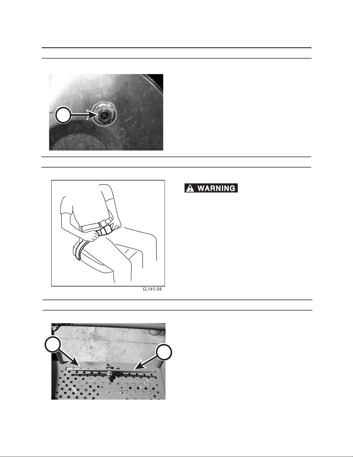
STABLIZER CONTROLS
MOVING STABILIZERS
43
Controls & Instruments
B
Unstable platform can
cause platform to tip or operator to fall, resulting in
severe personal injury or death.
Lower both stabilizers before operating.
Coming into contact with
stabilizers can cause serious personal injury or
death. Clear all personnel from work area before
lowering stabilizers.
Push right stabilizer control switch (A) down to lower
stabilizer.
Pull right stabilizer control switch (A) up to raise stabilizer.
Push left stabilizer control switch (B) down to lower
stabilizer.
Pull left stabilizer control switch (B) up to raise stabilizer.
A
Page 32
44
Controls & Instruments
C
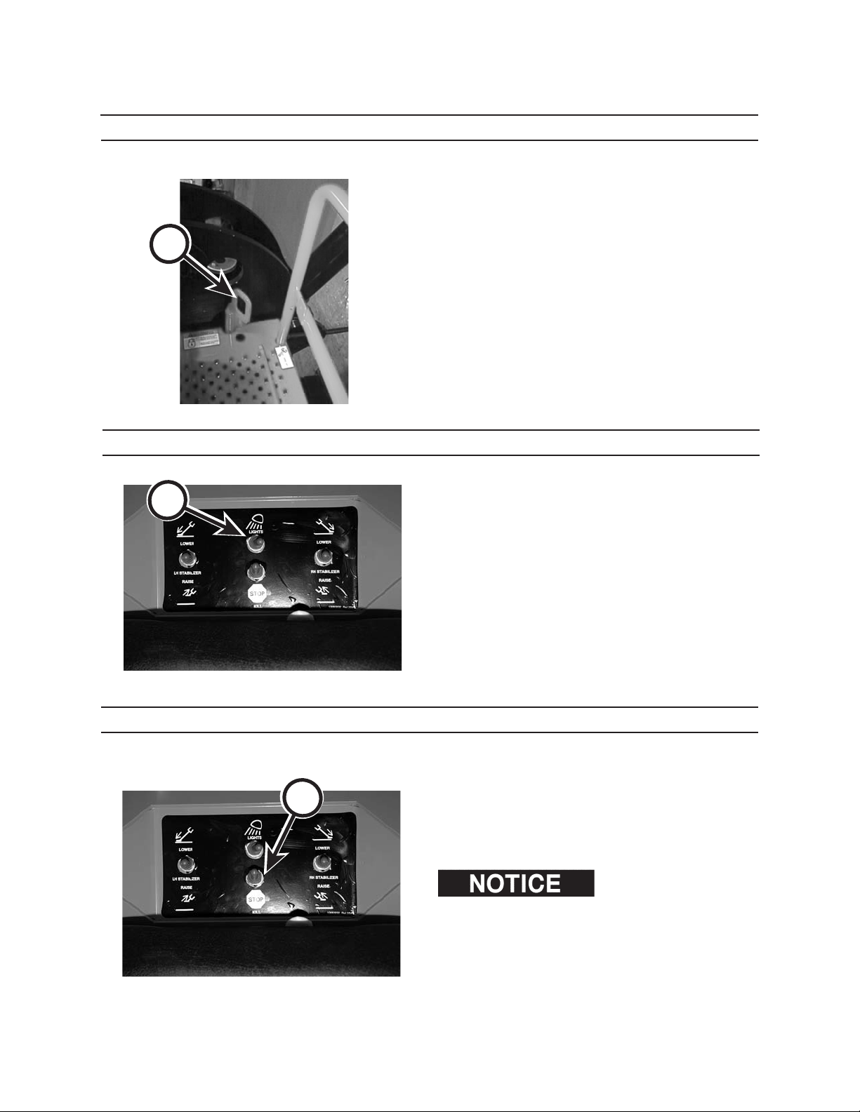
HYDRAULIC RESERVOIR SIGHT GAUGE
The hydraulic reservoir sight gauge (C) is located on
the hydraulic oil tank.
SEAT BELT OPTIONAL
A roll over or sudden stop
can cause severe personal injury or death.
A
To reduce risk of personal injury resulting from a roll
over or sudden stop, always wear a seat belt fastened
snugly when operating this machine.
This machine can change directions rapidly. It can start
and stop quickly. See Operation Section in this manual
for instructions on properly using the seat belt.
SWING PEDAL
Use the swing pedal to control the upper frame swing
as follows:
Press LEFT side of pedal (A) to swing upper frame to
B
the left.
Press RIGHT side of pedal (B) to swing upper frame to
the right.
Page 33
D
45
Controls & Instruments
TRANSIT LOCK
The transit lock (D) must be removed to operate
loader, and must be in place during transport.
Before removing transit lock and operating loader,
check around truck and loading area for personnel and
obstructions. Remove any personnel from immediate
work area.
LIGHTS OPTIONAL
A
Toggle light switch (A) to turn lights on and o.
STOP SWITCH OPTIONAL
B
To stop engine, pull toggle stop switch (B) toward
operator.
This stop switch can be used to stop truck engine
when needed.
restarted from operator’ s station. Be sure that loader
is positioned to allow the operator to safely dismount
loader using the ladder before shutting engine down.
Truck engine can not be
Page 34

46
Controls & Instruments
Page 35

51
Pre Start Inspection
This machine may not be used until operators have read, studied, and understand this
manual, and have learned how to properly operate this machine. Operating this machine without reading, studying,
and understanding this manual could result in severe personal injury or death.
Failure to perform a daily inspection of the machine could result in machine
damage and severe personal injury.
Inspector’s Initials
Machine Serial NumberDate of Inspection
PRESTART CHECKS: ON THE GROUND
Check for protective clothing (wear it) and safety equipment (know where it is).
Check entire machine by performing a thorough walk-around inspection.
Check for loose or missing parts. Tighten loose parts; replace missing parts.
Check for leaks in hydraulic hoses and /or lines (replace defective hoses and/or lines).
Check hydraulic hoses and lines for wear and/or damage. Replace any defective hoses and/or lines.
Check that machine has been properly lubricated as described in Scheduled and Periodic Maintenance
Services section.
Check shields and guards. They must be in place and undamaged. Replace damaged shields and guards.
Check that safety decals are on machine and that they are readable.
Check that shut-o valves are open (if equipped).
Check for dirt and grime on all hydraulic components. Remove dirt and grime to help prevent overheating.
Check for ice, snow, oil, mud, and grease on ladders and walkways. Clear away ice, snow, oil, mud, and grease
to prevent slips and falls.
Check for any loose or worn skid-resistant mats. Replace if loose or worn.
Check hydraulic oil reservoir level. Add hydraulic oil to reservoir if necessary.
Check for combustible or ammable materials. Remove them from machine, if found.
Check mounting hardware. Tighten, if necessary.
Check that machine will not be near electrical wires. See Operation section, for more details.
Check swing bearing for loose or missing fasteners. Tighten loose fasteners. Replace missing fasteners.
Check boom for damage, cracks, debris, mounting pin retention, and other problems. Immediately report
any structural problems (cracks) to an authorized dealer for diagnosis and repair or replacement.
Check that truck/trailer is on rm, level ground, and that parking brake is set.
Check electrical system for worn or frayed wires and/or loose connections.
Pages in this section may be copied. Check o each inspection
item before operating machine. File the copy as a record of
inspection as required by OSHA or local governing body.
Page 36
52
Pre Start Inspection
PRESTART CHECKS: ON THE PLATFORM
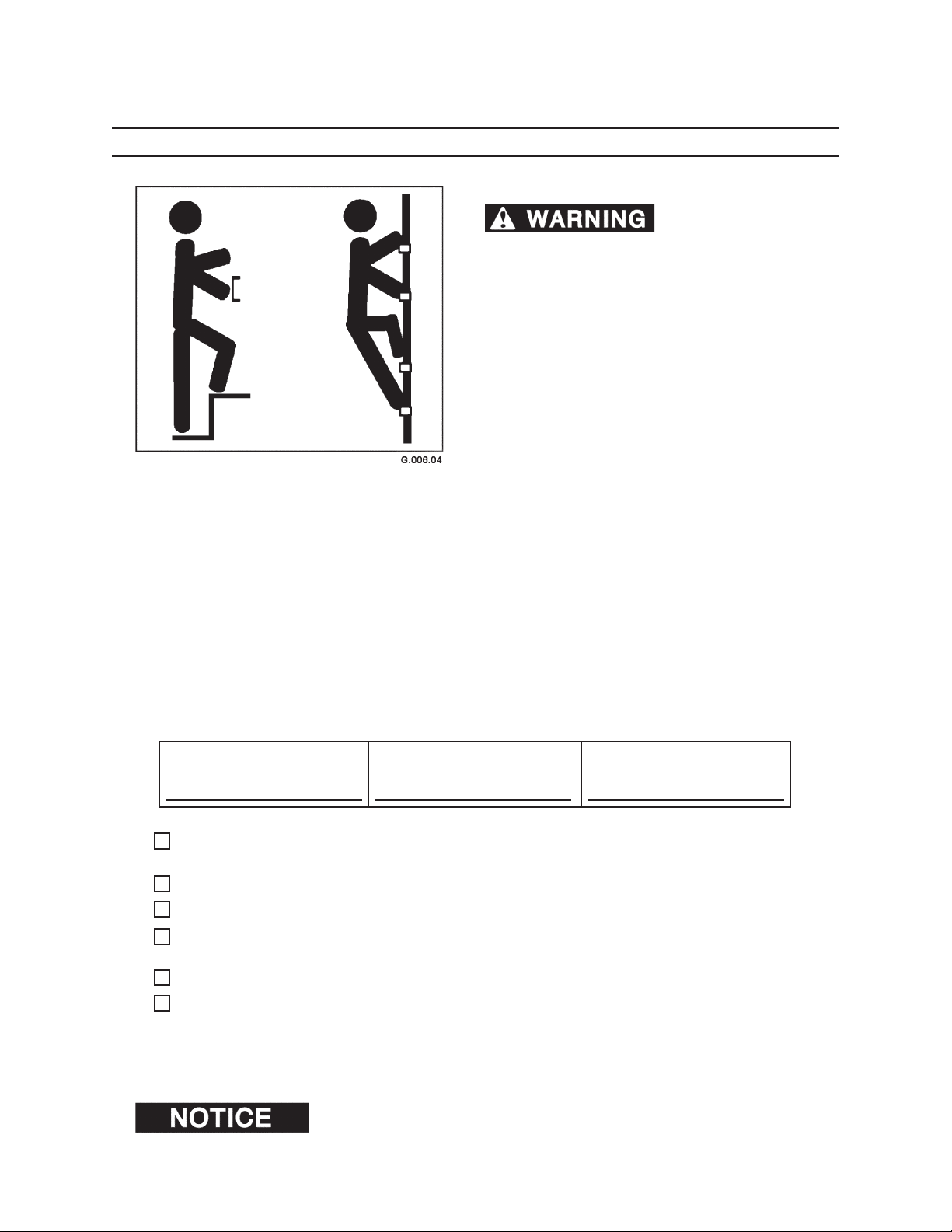
HAND HOLDS AND STEPS
Slips and falls can cause
severe personal injury or death.
Use provided hand holds and steps while maintaining at least 3 points of support (1 foot and 2 hands or
2 feet and 1 hand) when getting on and o machine.
Face machine when getting on and o of it.
Never use controls as hand holds. Never use steering
wheel as a hand hold. Moving the steering wheel from
its center position will COMPLETELY turn machine right
or left.
DO NOT mount machine if hand rails or steps are broken or missing. Get them repaired rst.
DO NOT jump on or o machine unless it has touched
a live electrical wire and it must be exited.
Ensure rm foot position when getting on and o
machine. Be careful of slippery conditions on platform, steps, and hand holds when getting on and o
machine.
Remove oil, grease, mud, ice, etc. before mounting or
dismounting machine.
To prevent slips and falls, replace skid-resistant material if it is worn, damaged or missing.
Inspector’s Initials
Check hydraulic hoses in platform/boom end area for leaks, abrasions, excessive wear, or other damage. Replace defective hoses and/or lines.
Check safety decals. They must be present and readable.
Check control levers for free movement.
Check booms for damage, cracks, debris, mounting pin retention, and other problems. Immediately report any
structural problems (cracks) to an authorized dealer for diagnosis and repair or replacement.
Check fuel tank (ll tank and end of shift to reduce water condensation).
Machine Serial NumberDate of Inspection
Check that seat belt (if equipped) works properly. Replace worn or damaged seat belt .
Pages in this section may be copied. Check o each inspection
item before operating machine. File the copy as a record of
inspection as required by OSHA or local governing body.
Page 37
53
Pre Start Inspection
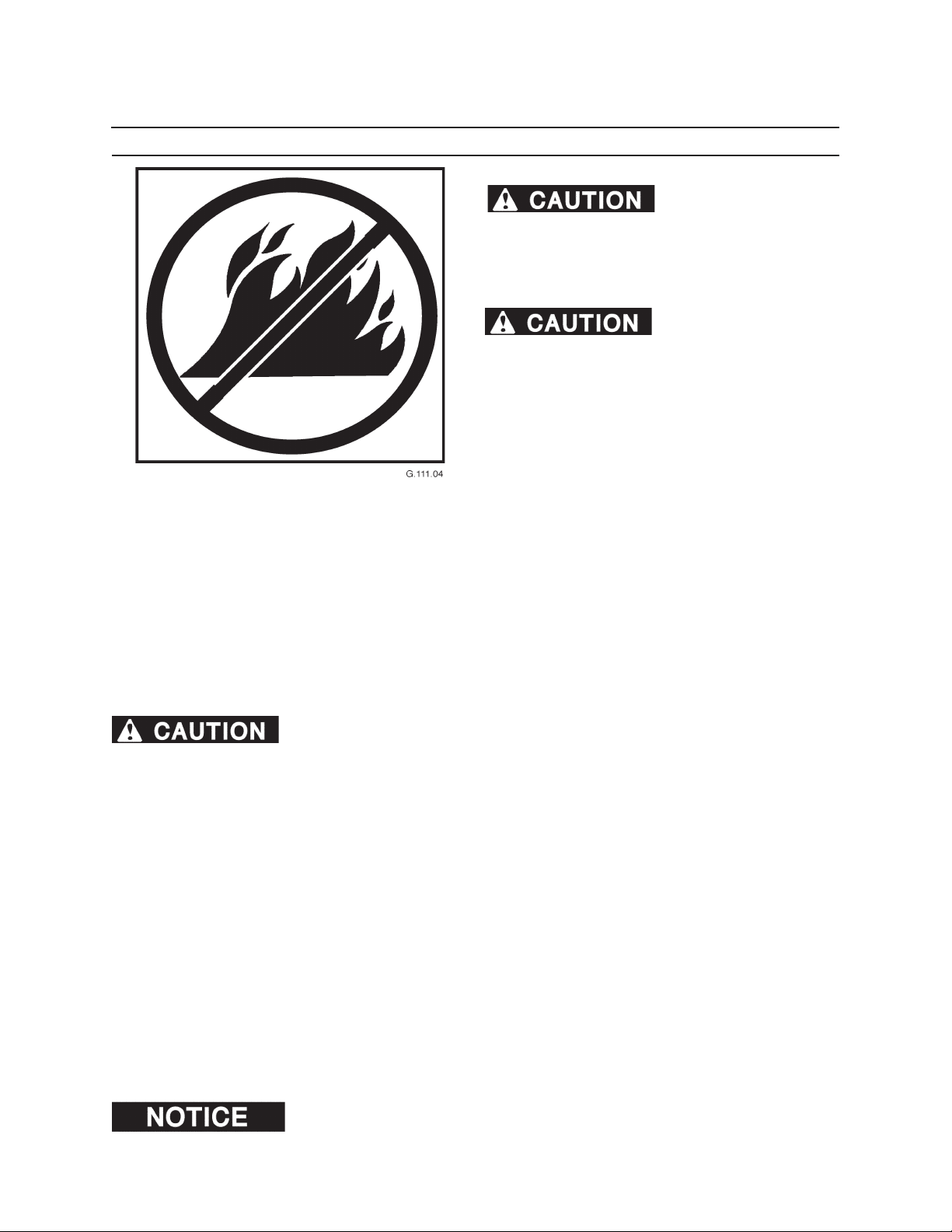
FIRE PREVENTION
Fires can cause personal
injury or machine damage.
Keep machine clean. Remove debris, especially from
heat sources. Fire prevention beats re ghting. Hourly
or daily inspections can reduce the possibility of re.
.Forest debris can collect
on the machine and cause a re. When forest debris
mixes with ammable uids in a hot, conned space,
the risk of a re starting greatly increases. KEEP THE
MACHINE CLEAN.
Check machine daily for re hazards. Remove debris from areas of the machine that create heat and that are
potential re start points. Depending on machine model, check for ammable debris in the following locations:
• Engine block • Turbocharger • Electrical connections
• Exhaust manifold • Battery • Control valves
Fire needs fuel. Remove combustible material (fuel for re) from heat sources. Keep the machine clean. Remove
the following materials, and other combustible materials from areas of the machine that create heat:
• Pine needles • Twigs • Debris
• Shop rags • Oil spills • Coolant mixture
• Leaves • Sticks • Sawdust
• Grease • Bark • Diesel fuel
Keep the machine clean. Risk of re increases if combustible materials and amma-
ble materials build up on machine. This machine is not designed to house or store combustible materials.
Much of the material found in forestry operations is highly ammable, including limbs, bark, leaves, saw dust,
small wood chips and pine needles. When the forestry debris is soaked with fuel or lubricants, the risk of re
is greatly increased. Doing a daily inspection before every shift, or more often based on the work activity and
build-up of debris, is the best way to prevent a machine re. Frequent inspections and thorough machine cleaning are critical when engaged in forestry operations, and even minor leaks or electrical malfunctions should be
repaired as soon as possible. Regularly remove ammable materials (such as diesel fuel, engine oil, hydraulic oil,
and grease) from all areas of the machine. Clean up after working. Keep the fuel and hydraulic systems in good
repair.
Highly ammable debris such as leaves, twigs, saw dust, small wood chips and pine needles can collect on and in
equipment used in forestry operations. If allowed to accumulate, the debris can rapidly become the fuel component of a machine re. Clean all accumulations of forest debris in the engine compartment or around other hot
areas and hot parts on the machine at the completion of each work shift or more frequently when working in
conditions where large amounts of forest debris are present.
Check hydraulic hoses, fuel lines, and ttings for leaks. Tighten loose ttings. If hoses or lines are bent, kinked, or
show signs of wear, install new parts. Check electrical connections to be sure they are clean and secure.
Frayed or worn insulation on battery cables or other wires may lead to electrical res. Check cables and wires and
replace if insulation is frayed, worn, or damaged.
At the end of each shift ALWAYS stay with the machine for 30 minutes after shutting down
the engine to ensure there is no forest debris/trash re start up. Keep a re extinguisher ready during this 30 minute
cool down period.
Page 38

54
Pre Start Inspection
Page 39
Operation
GENERAL GUIDELINES
Only a trained, qualied, and authorized operator shall be allowed to operate
this machine. Only use this machine after carefully reading this manual and learning
how to safely operate and maintain this machine. Unsafe operation can cause severe personal injury or
death.
OPERATOR PREPARATION
Operator must be fully trained, qualied, and authorized to operate this machine.
Before running this machine, operator must know the
location and purpose of
• controls
• indicator lights
• instruments
• local operating safety rules and procedures
• safety and instruction decals (see Safety Decals
section)
61
Operators must be at least 18 years old to operate this machine (Code of Federal Regulations: Labor).
Never operate this machine while under the inuence of drugs or alcohol. Use of prescription or over-the-counter drugs or medications requires advice from a medical practitioner on whether or not machine can be safely
operated.
Operators may not run this machine if subject to dizziness, seizures, or motion disturbance.
Do not operate this machine unless it is properly mounted to a truck or trailer for stability.
Never operate this machine with stabilizers in raised position.
No riders are allowed on this machine. Machine riders can fall from machine or be injured by movement of machinery, causing severe personal injury or death. Do not allow riders on a machine that is operating or moving.
Follow all safety operating instructions and practices. (See General Safety section.)
Keep machine away from power lines.
If this manual is lost, contact an authorized dealer for a new manual. Keep manual in the manual storage pouch
in the cab.
Report any noticeable machine problems to people who can repair the problems before machine is used.
Be sure cab windows are clean before operating machine. Cab windows must be clear of ice and frost. Replace
windows that are cracked, yellow, and/or hazy.
Do not operate delimber within 300 feet (91 meters) of personnel or property.
REMEMBER, OPERATORS ARE KEY TO THE SAFE OPERATION OF THIS MACHINE.
Page 40
62
Operation
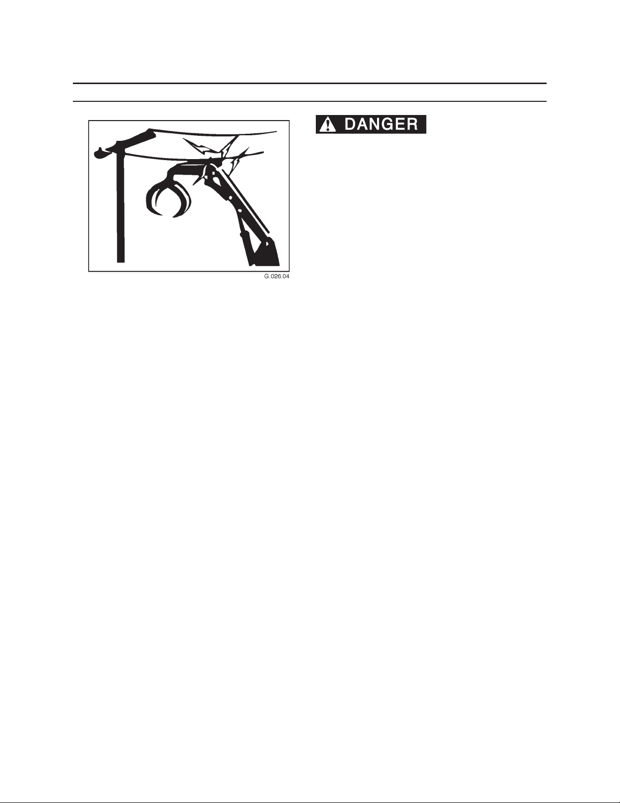
ELECTROCUTION DANGER
CONTACTING ELECTRIC
LINES WITH BOOM, LINE, OR LOAD WILL CAUSE
SEVERE INJURY OR DEATH. WATCH FOR OVER
HEAD POWER LINES. TREAT ANY LINE AS LIVE
AND DANGEROUS. IF AT ALL POSSIBLE, HAVE THE
POWER LINE DISCONNECTED BEFORE STARTING
WORK.
Never move any part of the machine or load closer to
electric lines than 10 feet plus twice the line insulator
length. A line insulator is what connects an electric line
to an electric pole.
For example, if a line insulator is 6 inches long, stay at
least 10 feet plus twice the line insulator length (2 x 6 =
12 inches or 1 foot) from the electric line, which means
stay at least 11 feet from this electric line.
If the machine touches an electric line, stay in the machine. Carefully move machine or load away from the
electric line, without pulling the line down.
DO NOT let anyone else touch the machine while it is
touching the electric line. If machine cannot be moved
away from the electric line without pulling the line down,
have someone contact the utility company to disconnect power from the line. If this is not possible, or if the
machine begins to burn, jump away from the machine to
the ground with both feet together, in one smooth jump.
DO NOT touch the machine and the ground at the same
time or else the electricity in the line will go through your
body. Get away from the machine by jumping with both
feet together.
Notify the utility company immediately. DO NOT let
anyone near the machine while it is touching the electric
line.
Page 41
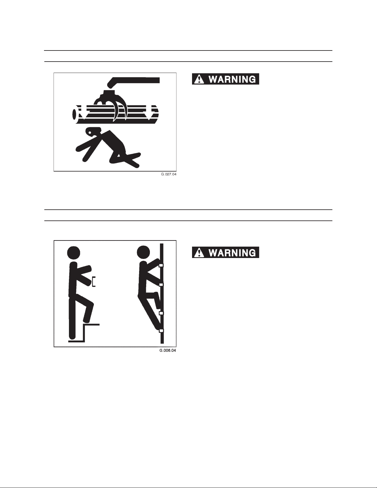
OVERHEAD LOADS
booms can cause severe injury or death.
The loader operator is responsible for ensuring that
booms or loads are never suspended over or near
personnel.
• Always know where other people are working at
the job site in relation to the loader.
• Maintain good communication with everyone on
the job.
• Stop operations if someone on the ground ap-
proaches the machine.
63
Operation
Falling or swinging logs or
GETTING ON MACHINE
HAND HOLDS AND STEPS
severe personal injury or death.
Use provided hand holds and steps while maintaining at least 3 points of support (1 foot and 2 hands or
2 feet and 1 hand) when getting on and o machine.
Face machine when getting on and o of it.
Never use controls as hand holds. Never use steering
wheel as a hand hold. Moving the steering wheel from
its center position will COMPLETELY turn machine right
or left.
DO NOT mount machine if hand rails or steps are broken or missing. Get them repaired rst.
DO NOT jump on or o machine unless it has touched
a live electrical wire and it must be exited.
Ensure rm foot position when getting on and o
machine. Be careful of slippery conditions on platform, steps, and hand holds when getting on and o
machine.
Slips and falls can cause
Remove oil, grease, mud, ice, etc. before mounting or
dismounting machine.
To prevent slips and falls, replace skid-resistant material if it is worn, damaged or missing.
Page 42
64
Operation
MACHINE START UP
1. Postion truck on rm, level ground.
2. Perform a pre-start inspection (refer to
Section 5, Pre-Start Inspection).
3. Before start up, walk completely around machine
and make sure no obstacles or personnel are in
the area.
4. Maintain adequate distance between machine
and other equipment and personnel.
5. Mount loader (refer to Getting on Machine in this
section).
6. Lower stabilizers (refer to Lowering Stabilizers in
this section).
7. Remove transit lock (refer to Unlocking Transit
Lock in this section).
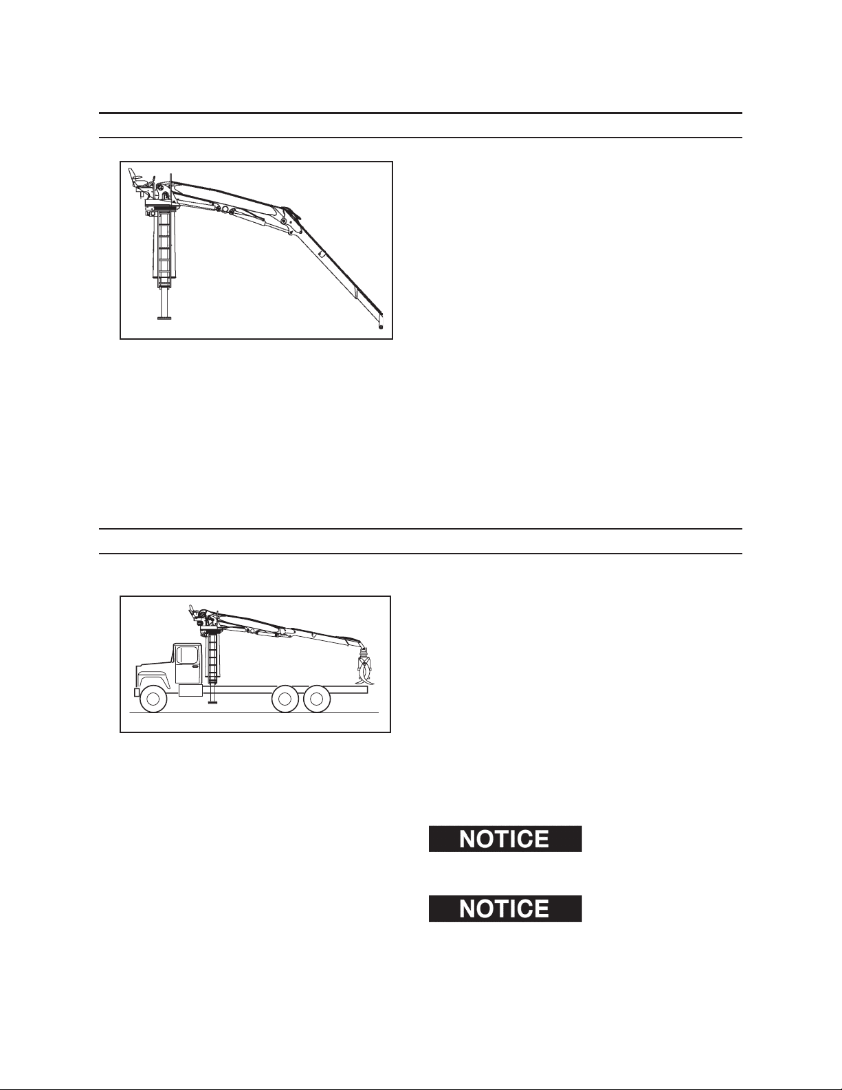
ENGAGING POWER TAKE OFF PTO
1. Park truck in safe location.
2. Check around truck and loading area for person-
nel and obstructions.
3. Set parking brake.
4. Be sure truck transmission is in neutral position.
5. Perform pre-start inspection (see Section 5, Pre-
Start Inspection).
6. Engage power take o (PTO) to activate the pump.
7. Increase engine speed to achive recommended
pump speed of 1750 rpm. Engine speed depends
on pump drive ratio.
tioned so that all functions can be cycled through their
full range without obstructions when starting operations.
maximum recommended PTO speed of 1750 rpm.
Machine should be posi-
Do not exceed
Page 43
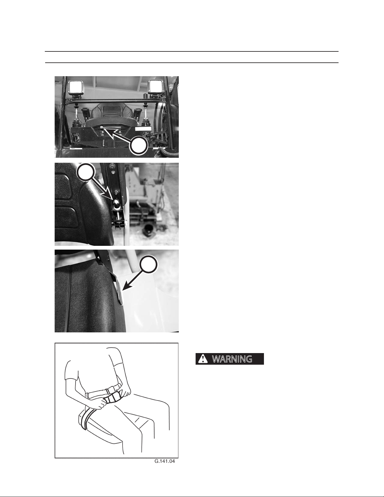
ADJUSTING OPERATOR’S SEAT
WARNING
Adjust operator’s seat using the following guidelines:
SEAT FRONT AND REAR POSITION
Side lever (A) left or right.
While seated, slide seat to desired position.
Release lever.
A
65
Operation
B
C
ARMREST
To adjust armrest position, turn knob (B) clockwise
or counterclockwise until armrest is in desired position. Push down on arm rest to lower while operating
loader.
SEAT BACK
When transporting loader, fold seat back down. Do
this by pulling up on lever (C) and pushing down on
back (toward seat).
To raise seat back, pull up on lever (C) adjusting seat
to desired position. Release lever to lock into desired
position.
SEAT BELT OPTIONAL
A rollover or sudden stop
can cause severe personal injury or death.
Always wear your seat belt, fastened snugly, when operating machine to reduce the risk of personal injury
resulting from a rollover or sudden stop.
Page 44
66
Operation
A
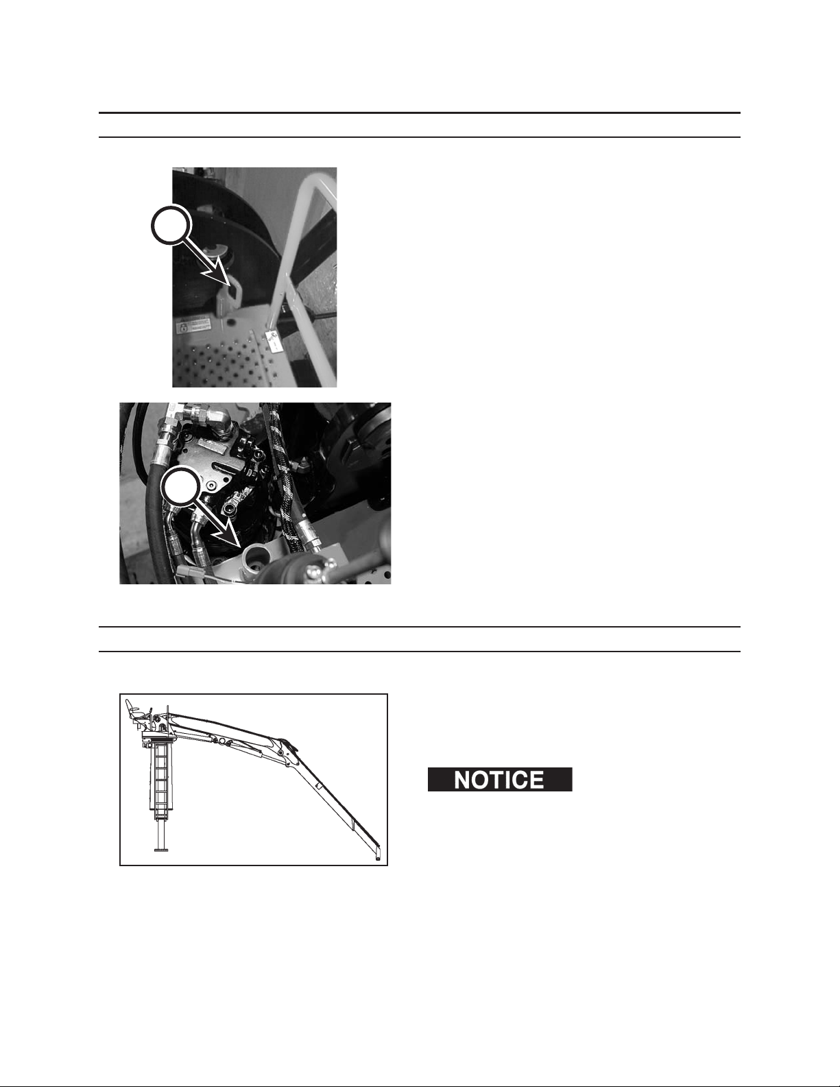
UNLOCKING TRANSIT LOCK
Transit lock (A) must be removed to operate loader.
To remove, pull up rmly on transit lock. Store lock in
space left of operator’s seat (B).
Check around truck and loading area for personnel
and obstructions. Any person in the immediate area
(300 feet), must be aware that work will begin soon.
B
WARM UP PERIOD
1. Be sure area is clear of personnel.
2. Engage PTO.
3. Run transport engine at idle speed for 5 minutes.
It is important to allow the
hydraulic system to reach operating temperature before
beginning operation. Cold and thick oil cannot ow fast
enough to the pump to meet output demand. Cavitation
and extreme damage may be caused by operating the
machine when the hydraulic oil is too cold to ow easily.
4. Warm up the hydraulic system by
• engaging and disengaging controls to help
speed warm up of hydraulic components,
and;
• cycling all controls to allow warm oil to circulate through all cylinders and lines.
Page 45
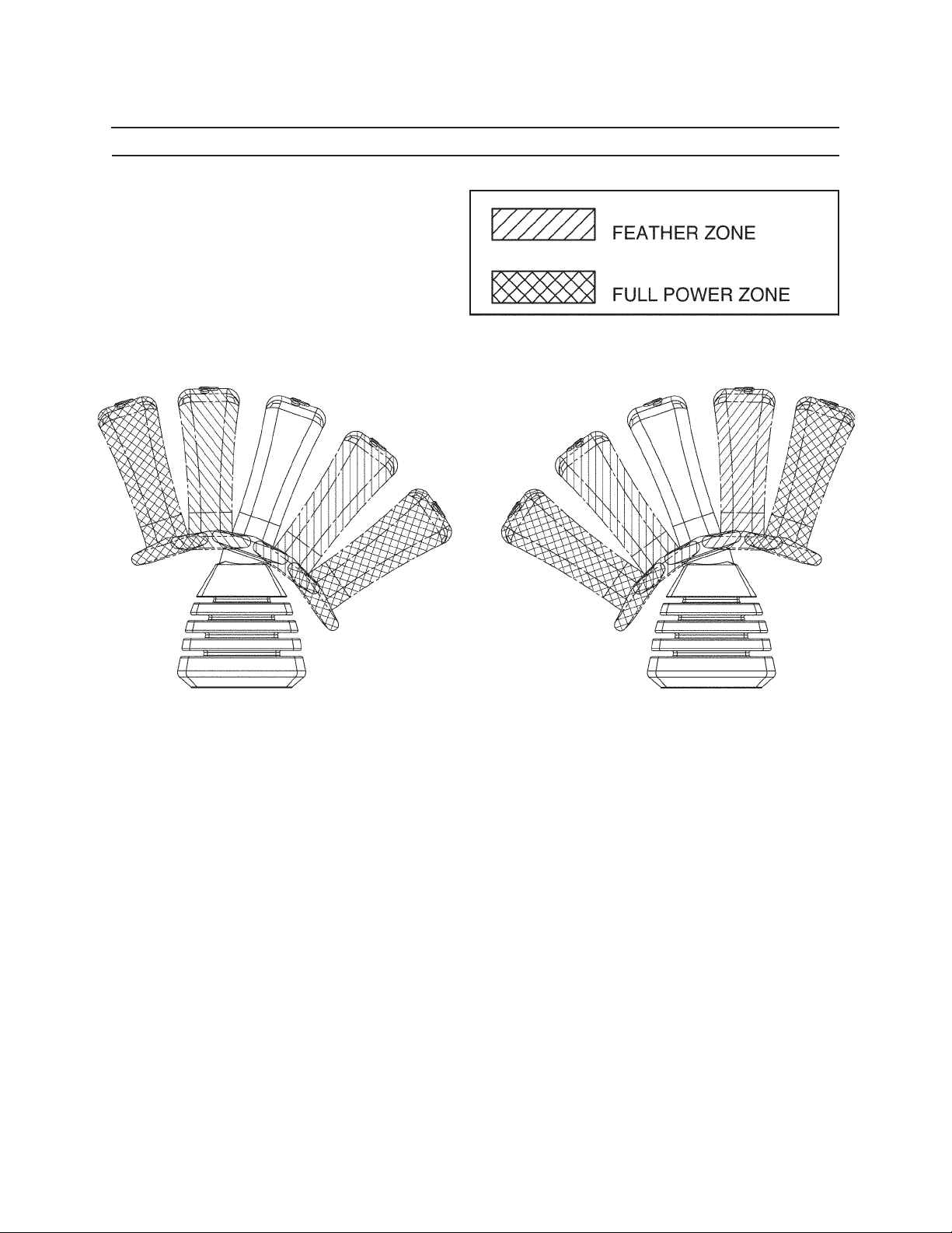
FEATHERING THE CONTROLS
67
Operation
Rough operation can be dangerous, hard on the machine, and hard on the operator.
DO NOT jerk control levers to full speed, or from one direction to another.
Feather controls this way:
1. Move joystick control gently from neutral to start motion.
2. After a slow, smooth start, move joystick control to desired speed position.
3. Just before stopping movement, move joystick control gently back to neutral.
This method of carefully manipulating the controls is called feathering. Work can done more eciently by feathering controls than by jerking controls.
There is a rhythm to operating this machine. Feathering the controls will help the operator nd and take advantage of this rhythm.
Page 46
68
Operation
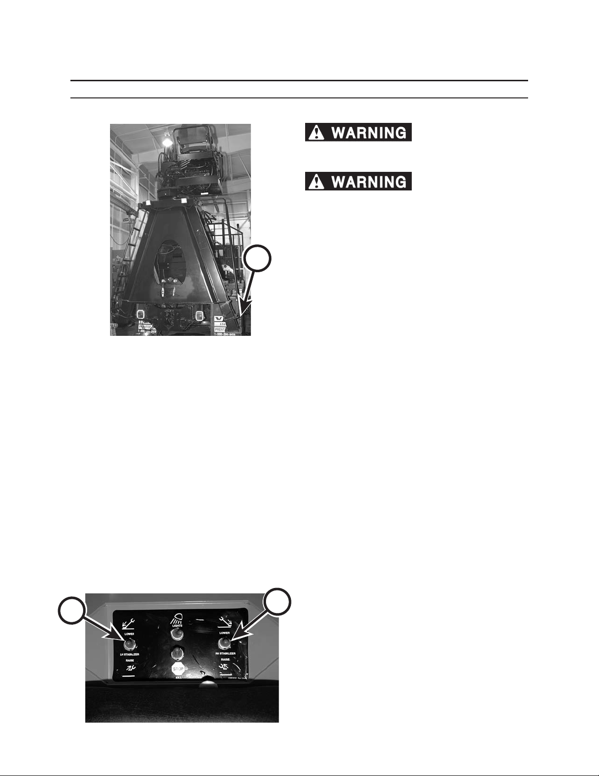
USING STABILIZERS
cause severe personal injury or machine damage.
Lower both stabilizers before operating machine.
stabilizers can cause serious personal injury or
death. Clear all personnel from work area before
lowering stabilizers.
It is the responsibility of the operator to make sure all
A
personnel are clear of the stabilizers (A) before lowering them. When setting the stabilizers, make sure they
are sitting on rm, solid ground.
DO NOT set stabilizers on rocks, stumps, curbs, edge of
paving, etc. or on soft or unstable ground.
1. Position loader on rm, level ground.
Unstable platform can
Coming into contact with
STABILIZER CONTROL SWITCHES
Left Stabilizer (B)
Forward Position (away from seat):
Lower stabilizer
Rear Position (toward seat):
Raise stabilizer
Right Stabilizer (C)
Forward Position (away from seat):
Lower stabilizer
Rear Position (toward seat):
Raise stabilizer
B
C
2. Double check to ensure no persons are close to
truck and/or loader.
3. Clear ice and snow from the area where the
stabilizer pads will be lowered. Do not operate or
position loader on slippery surfaces.
4. Lower stabilizer legs until partial load has been removed from truck or trailer tires to achieve stable
operating position. The truck or trailer tires should
not be o the ground.
5. Follow these stabilizer operating guidelines:
• Never allow another person to be on the
loader or in and around the truck when lowering or raising stabilizers.
• Lift boom from transport position and make
a test lift to check ground conditions under
stabilizers.
• Never operate machine with stabilizers in
raised position.
• Use extra precautions at maximum reach until
additional weight of payload adds to loader’s
stability.
Page 47
69
Operation
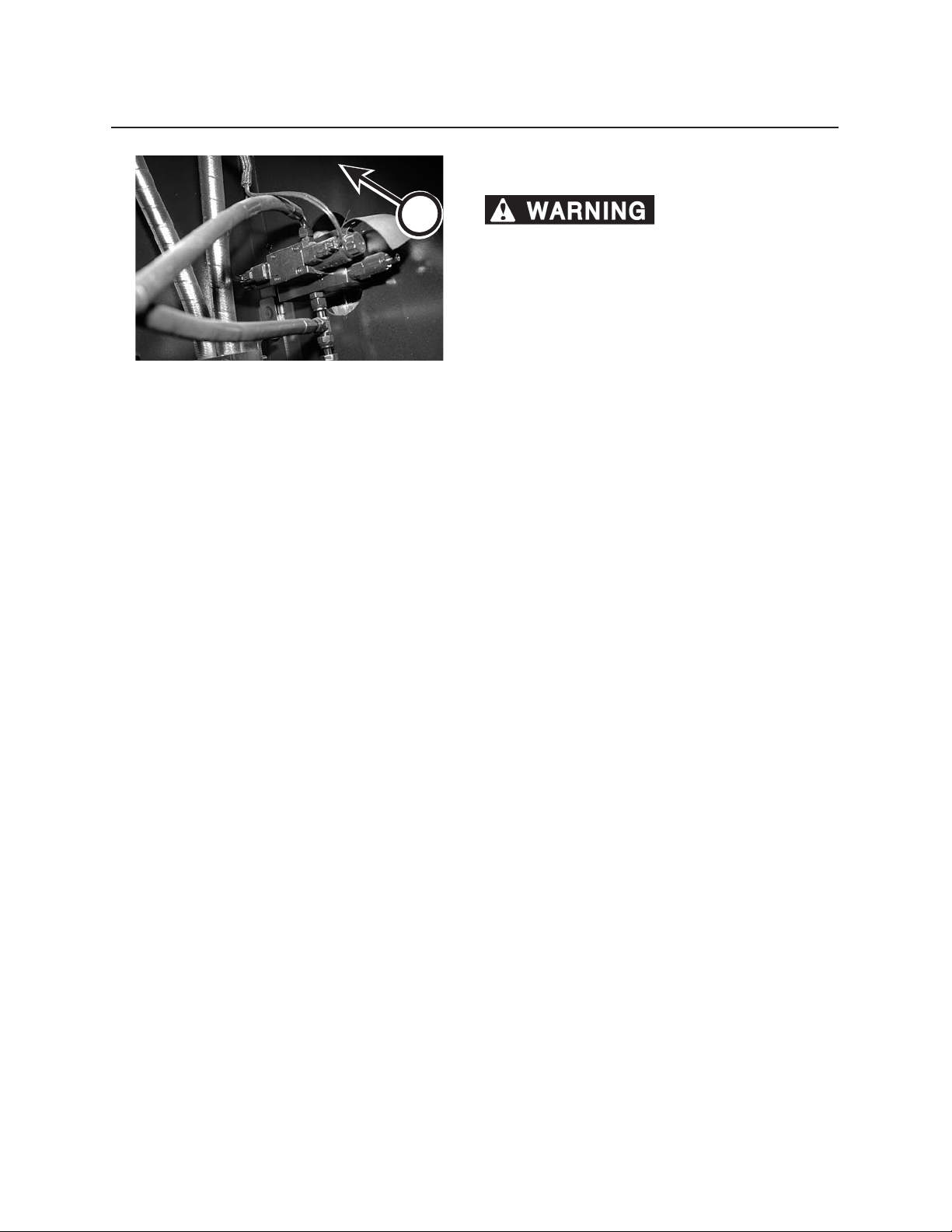
RETRACTING STABILIZERS IN THE EVENT OF LOSS
OF ELECTRICAL POWER
A
Coming into contact with
stabilizers can cause serious personal injury or
death. Keep all personnel clear of stabilizers.
1. Equipment needed: 5/32 steel rod and rope or
strap.
2. Verify pump is running and truck engine is at idle
speed.
3. Engage transit/swing lock.
4. Fully depress and hold swing pedal with rope or
strap.
5. Depress override switch on stabilizer valve (A), us-
ing 5/32 steel rod.
6. Stabilizer valve will shift, allowing cylinder retrac-
tion.
Page 48
610
Operation
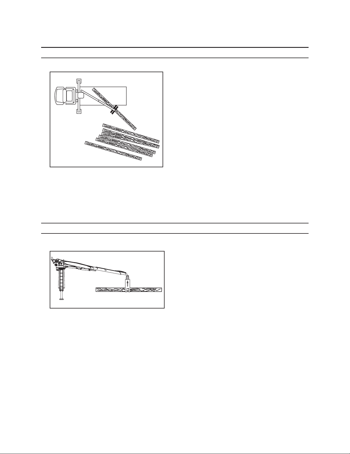
LANDING LAYOUT
• The loader operator is in one of the best positions
on the work site to notice a problem and warn
others. The loader operator is responsible for the
safety of people on the ground.
• All landings (decks) should provide an area clear
of suspended loads for landing personnel (deck
hands) to work. Remember, logs can roll or be
thrown a considerable distance.
• If clearance of suspended loads cannot be pro-
vided, STOP loading operations and lower grapple
while deck hands are working on the landing.
• All obstructing trees should be removed to ensure
clearance for loading.
• Never locate landing near overhead electrical
lines. See Electrocution Dangers in this section for
instructions.
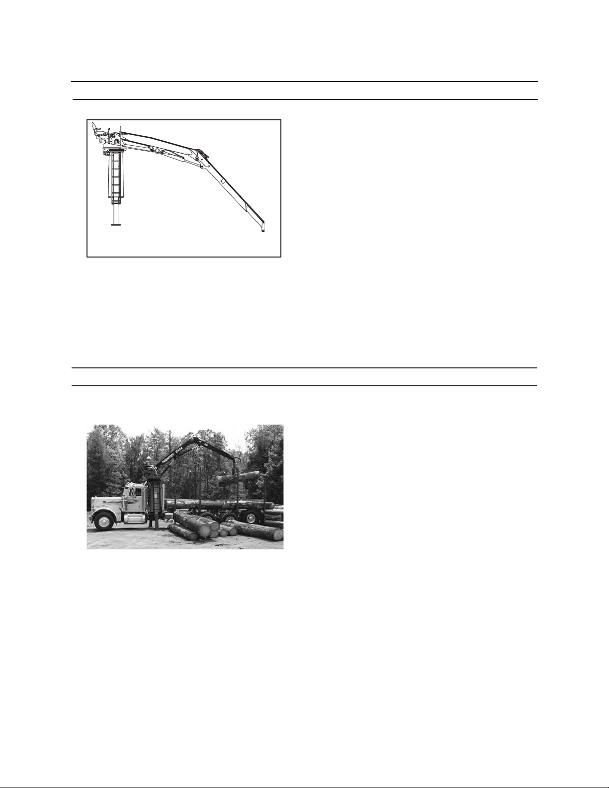
PICKING UP LOGS
• Never pinch a log. Always make sure the grapple
wraps around the log.
• Never swing load or grapple over truck cab.
• Make sure other personnel are away from truck
and loader when operating loader.
• Take care when rotating logs to make sure they
clear the loader and other obstructions.
Page 49
GRAPPLE CONTROL
Study and learn the grapple control functions (see
Section 3, Controls and Instruments). Improper rotation
of grapple or accidental opening of grapple will cause
loss of control of the load.
• Do not change function arrangement.
• Use proper grapple to match application.
• For log handling always use a log bypass, or com-
bination bypass/pulp grapple.
• For short wood handling, use a log bypass, combi-
nation bypass or butt-style pulpwood grapple.
• Never swing and load a single log or branch by
pinching the sides of the log or stem with the
grapple jaw tips. Always clamp the log or branch
within the grapple jaws.
611
Operation
STOPPING THE MACHINE
1. Bring loader to a complete stop.
2. Lower attachment to truck bed with the main and
stick booms extended. The grapple should be
open with the jaw tips on the truck bed.
3. Engage transit/swing lock pin.
4. Slow engine to LOW IDLE. Run engine at low idle
for at least 2 minutes to cool engine.
5. Turn key switch to OFF to stop the engine.
6. Remove key from ignition switch.
Page 50
612
Operation
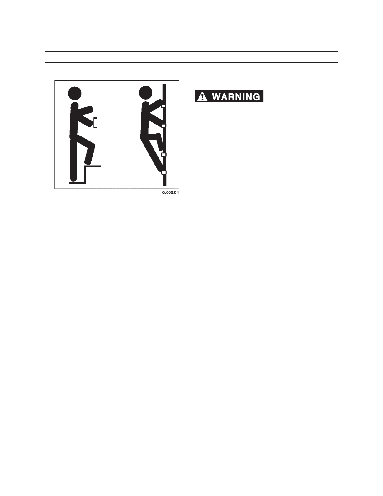
GETTING OFF MACHINE
HAND HOLDS AND STEPS
Slips and falls can cause
severe personal injury or death.
Use provided hand holds and steps while maintaining at least 3 points of support (1 foot and 2 hands or
2 feet and 1 hand) when getting on and o machine.
Face machine when getting on and o of it.
Never use controls as hand holds. Never use steering
wheel as a hand hold. Moving the steering wheel from
its center position will COMPLETELY turn machine right
or left.
DO NOT mount machine if hand rails or steps are broken or missing. Get them repaired rst.
DO NOT jump on or o machine unless it has touched
a live electrical wire and it must be exited.
Ensure rm foot position when getting on and o
machine. Be careful of slippery conditions on platform, steps, and hand holds when getting on and o
machine.
Remove oil, grease, mud, ice, etc. before mounting or
dismounting machine.
To prevent slips and falls, replace skid-resistant material if it is worn, damaged or missing.
Page 51
71
Break In Period
2124 LOADER
3
4
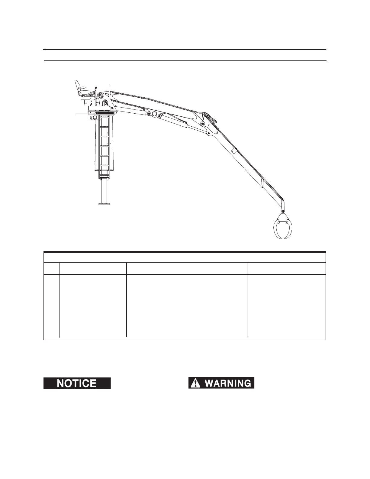
AFTER FIRST 10 HOURS OF OPERATION
KEY COMPONENT SERVICE SPECIFICATION
1. Hydraulic Reservoir* Check uid level - 42 gallons (159 L) Full mark. Use
Premium A.S. Hydraulic Fluid
2. Loader* Visually check for any loose hardware
or uid leaks.
3. Outer Swing Bearing Check tightness; torque if necessary 360 ft-lbs (490 N•m)
Fasteners
4. Inner Swing Bearing Check tightness; torque if necessary 730 ft-lbs (993 N•m)
Fasteners
* - Not shown
The above uid capacity is
approximate value. Be sure to check level after lling. DO
NOT OVERFILL.
ner capscrews on the swing bearing can cause the
upper and lower frame to separate, causing severe
injury or death. Read and follow all torque instructions in this manual.
Loose outer bolts or in-
Page 52
72
Break In Period
3
1
2
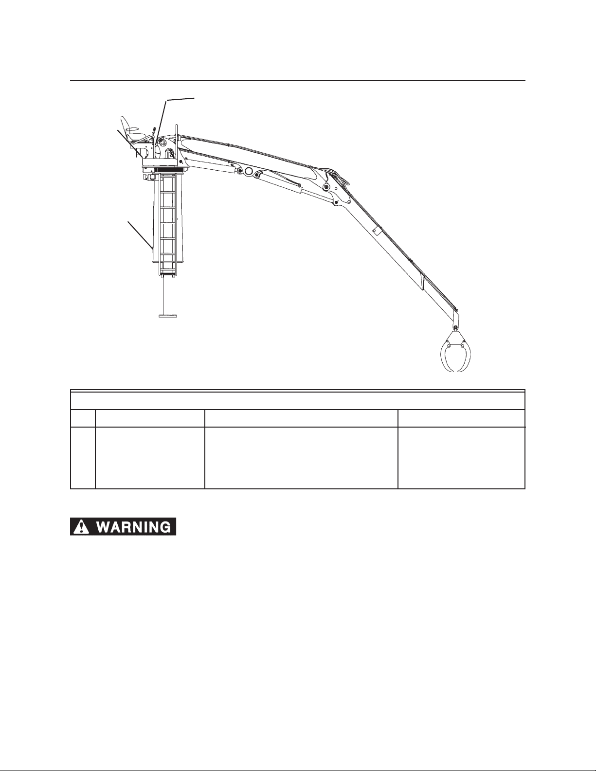
AFTER FIRST 100 HOURS OF OPERATION
KEY COMPONENT SERVICE SPECIFICATION
1. Hydraulic Return Replace Use genuine parts
Line Filters
2. Swing Drive Fasteners Check tightness; torque if necessary 160 ft-lbs (218 N•m)
3. Swivel Fasteners Check tightness; torque if necessary 76-84 ft-lbs (103-114 N•m)
* - Not shown
Loose outer bolts or inner capscrews on the swing bearing can cause the upper
and lower frame to separate, causing severe injury or death. Read and follow all torque instructions in this
manual.
DURING THE FIRST 100 HOURS OF OPERATION
1. Check all accessible hardware for tightness.
2. Check hydraulic uid regularly.
TO TIGHTEN A LOOSE BOLT OR CAPSCREW, DO THE FOLLOWING:
1. Torque the bolt or capscrew to recommended ft-lbs. Recheck every 10 hours.
2. Check the two adjacent bolts (on either side of loose bolt) for proper torque and recheck every 10 hours.
3. If any of these bolts or capscrews do not take the torque, or come loose again, they must be replaced, in-
cluding adjacent bolts/capscrews. Replace with factory-approved parts.
Page 53
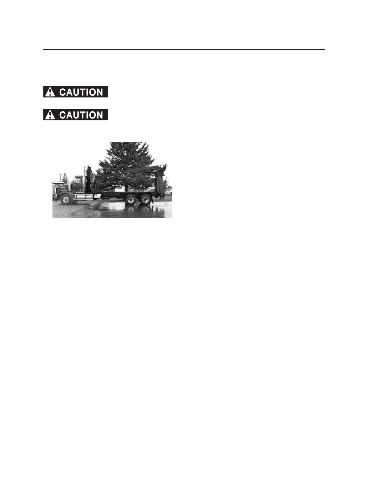
81
Transporting
The safety of the operator and those in the immediate work area depend on the operator using care and good
judgement in operating this equipment. Know the positions and functions of all controls, and make sure all
personnel are clear of the work area before attempting to operate this machine. See Operation section for more
information.
Failure to engage Transit Lock can cause personal injury or property damage.
Engage Transit Lock before transporting loader.
Improper positioning of loader during transport or movement could cause personal
injury or property damage.
BEFORE transporting this equipment, perform the following:
• Mount loader as if for operation (see Operation
section).
• Swing upper frame clear of obstacles until it centers with grapple carrier.
• Lower booms until they rest in cradles. Lower
grapple until it rests in grapple carrier.
• Engage turntable Transit Lock.
• Raise stabilizers.
• Recline seat.
• Dismount (see Operation section).
• Disengage PTO to shut down hydraulic pump.
• Secure grapple to grapple carrier with chain.
• Secure any attachment(s) with chain.
• Observe all highway height and weight limitations
(13.5 ft. [4.15 m] maximum load height).
• Do not ride on loader while moving truck or transporting loader.
Page 54

82
Transporting
Page 55
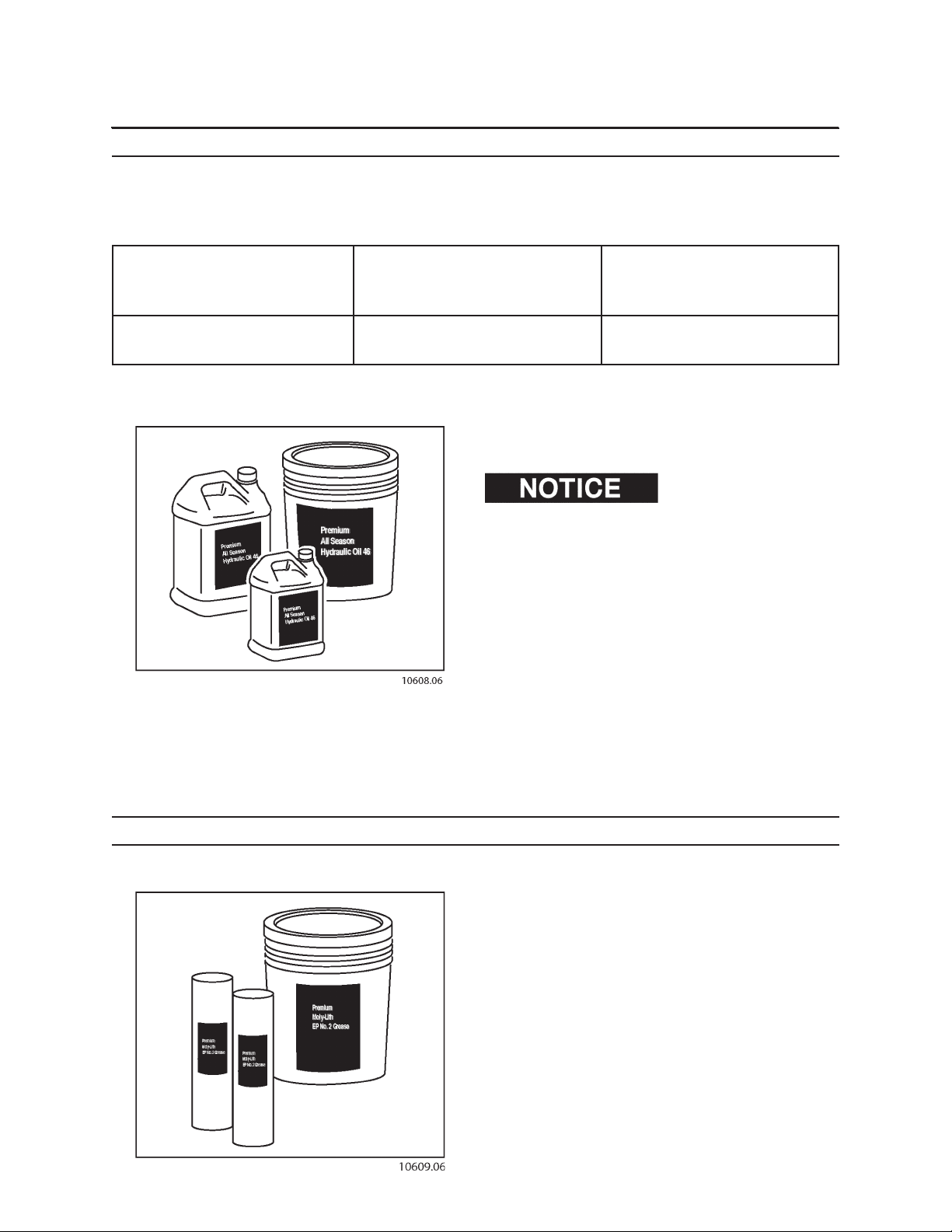
Fuels & Lubricants
HYDRAULIC OIL
Hydraulic systems have been lled from the factory with Premium All-Season Hydraulic Oil 46.
Use the following hydraulic oils in your machine.
AMBIENT TEMP AMBIENT TEMP AMBIENT TEMP
25°F TO 80°F 10°F TO 95°F 0°F TO 105°F
32°C TO 27°C 23°C TO 35°C 18°C TO 41°C
Premium All-Season Premium All-Season Premium All-Season
Hydraulic Oil 32 Hydraulic Oil 46 Hydraulic Oil 68
The hydraulic reservoir capacity is approximately 42
gallons (159 L).
Check with an authorized
dealer for hydraulic uid recommendations and compatibilities.
91
BE SURE hydraulic uid selection is compatible with
the hydraulic system.
BE SURE hydraulic uid selection assistance is from a
reputable supplier.
BE SURE hydraulic specications meet or exceed the
Premium All Season Hydraulic Oil specications. See a
Prentice machine dealer.
BE SURE to use a mineral-base hydraulic oil.
GREASE
Most lubricated ttings require Premium Moly-Lith EP
#2 Grease. However, there are special requirements for
the swing bearing and swing drive motor (see Grease
for Swing Bearing and Swing Drive Motor in this section).
Page 56
92
Fuels & Lubricants
GREASE FOR SWING DRIVE BEARING AND SWING DRIVE MOTOR
Follow these specications when selecting a grease for the swing bearing and swing drive motor.
AMBIENT TEMPERATURE RECOMMENDED LUBRICANT
Above 32°F (0°C) Premium Moly-Lith EP #2 Grease
Below 32°F (0°C) EP1 Grease
LUBRICANT FOR PINION AND SWING GEAR TEETH
When lubricating the pinion gear and swing gear teeth, use moly-lith open gear lubricant.
When the gear path becomes contaminated, clean with solvent to remove contamination. Relubricate gear with
moly-lith open gear lubricant, available from an authorized dealer.
CYLINDER ROD CORROSION PREVENTIVE
If machine will be stored for an extended period, or stored in a corrosive environment
(such as salt air or industrial pollution), apply Chrome Kote Corrosion Preventive on all portions exposed to air. See
Storage section for more information.
Page 57
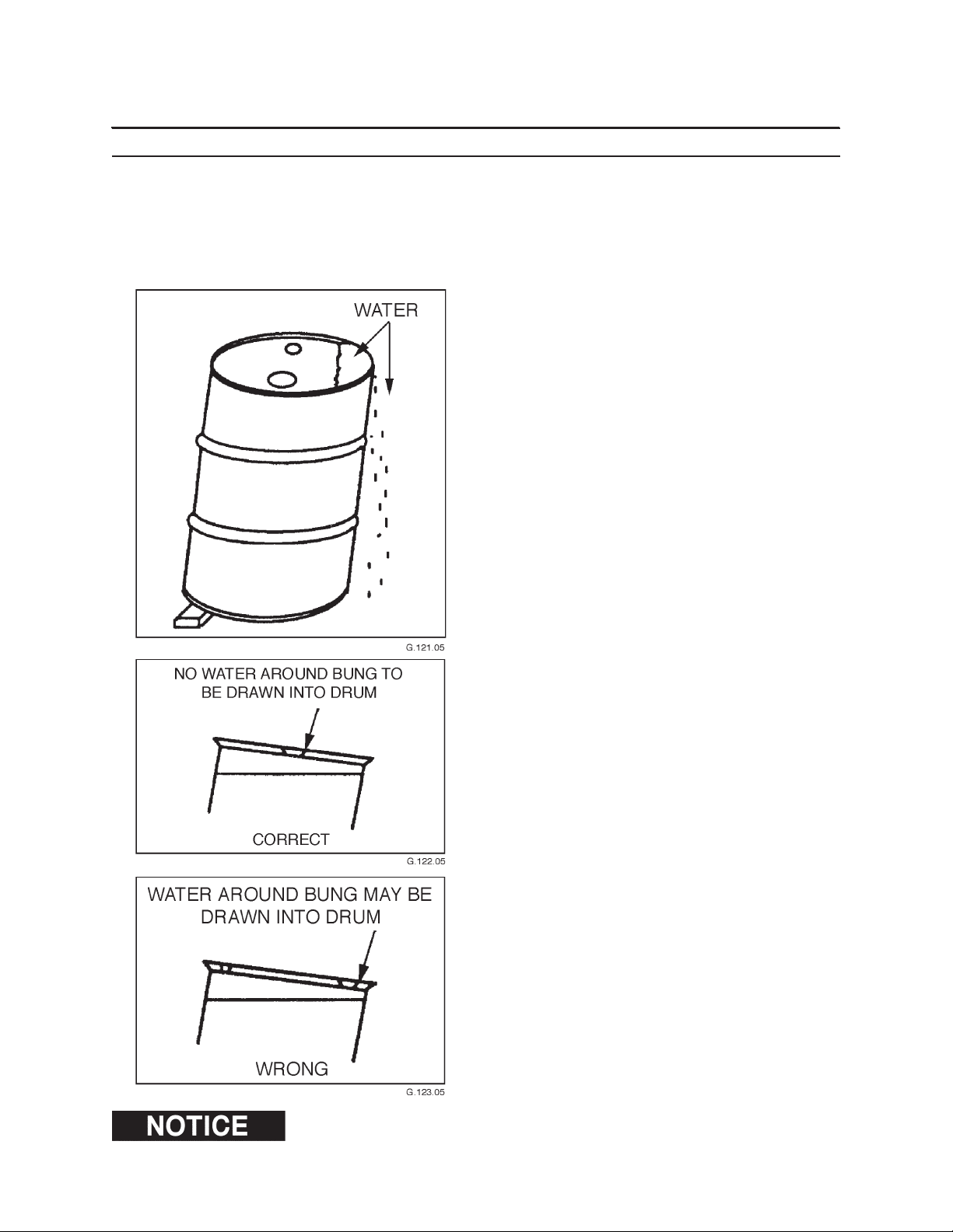
93
Fuels & Lubricants
STORING LUBRICANTS
Store lubricants in a clean area that will keep them protected from water, dirt, or other contamination.
Always use clean containers when handling lubricants.
Storing lubricant drums or other containers outdoors is poor practice. To minimize the harmful eect of unavoidable outdoor storage, a few simple precautions and procedures can be very helpful.
1. Generally, lubricants in containers smaller than
drums (55-, 30-, and 16-gallon oil drums, and
400- and 120-pound grease drums) should never
be stored outdoors. When drums must be stored
outdoors, a temporary shelter or lean-to, or a waterproof tarp will protect them from rain or snow.
2. Drums should be placed on their sides with the
bungs approximately horizontal. In this position,
bungs are below the level of the contents so that
breathing of water or moisture is greatly reduced
and water cannot collect inside chine (ridge of
drum). For maximum protection, drums should
be stood on end with bung end down on a welldrained and contained surface. Where all of these
approaches are not practical, drum covers may
be used. Drum covers are available in metal and
plastic.
3. When drums must be stored outdoors with bung
end up, they should be blocked up with bungs
parallel to the block to keep water away from the
bung openings.
4. Drums that have a bung on the side should be
stored either on end or on their side with the
bung down. Regardless of their position, drums
should always be placed on blocks or racks several
inches o the ground to avoid moisture damage.
DISPOSE OF USED FLUIDS PROPERLY.
If machine will be stored for an extended period, or stored in a corrosive environment
(such as salt air or industrial pollution), using a sponge, apply Chrome Kote Corrosion Preventive to portions exposed
to air. See storage section for more information.
Page 58

94
Fuels & Lubricants
Page 59
BEFORE MAINTENANCE
Maintaining this machine improperly could result in severe personal injury or
death. Read this manual before doing maintenance. Follow all safety instructions.
1. Read all safety and maintenance instructions in
this operator’s manual.
2. Position machine on rm, level ground.
3. Lower attachment to the ground.
4. Shut engine down.
5. Move controls in all directions to relieve hydraulic
pressure.
6. Remove key from ignition.
101
Maintenance Safety
PRACTICE SAFE MAINTENANCE
Read service and maintenance manuals and understand service procedures before performing service/
maintenance.
Understand service procedures before performing
maintenance. When performing maintenance, keep
area around machine clean and dry.
DO NO service machine while it is moving. Keep away
from power-driven parts. Lower attachment to the
ground. Disengage power. Shut engine down. Move
controls in all directions to relieve hydraulic pressure.
Remove key from ignition. Allow machine to cool
down.
Support all raised equipment.
Keep all machine parts in good condition, and be sure
parts are properly installed. Repair damage immediately. Repair all hydraulic and fuel leaks immediately.
Replace worn or broken parts. Remove any buildup of
grease, oil or debris.
Disconnect battery ground cable (-) before adjusting
the electrical system.
Lower stabilizers to the ground. Do not support machine weight on stabilizers.
Page 60
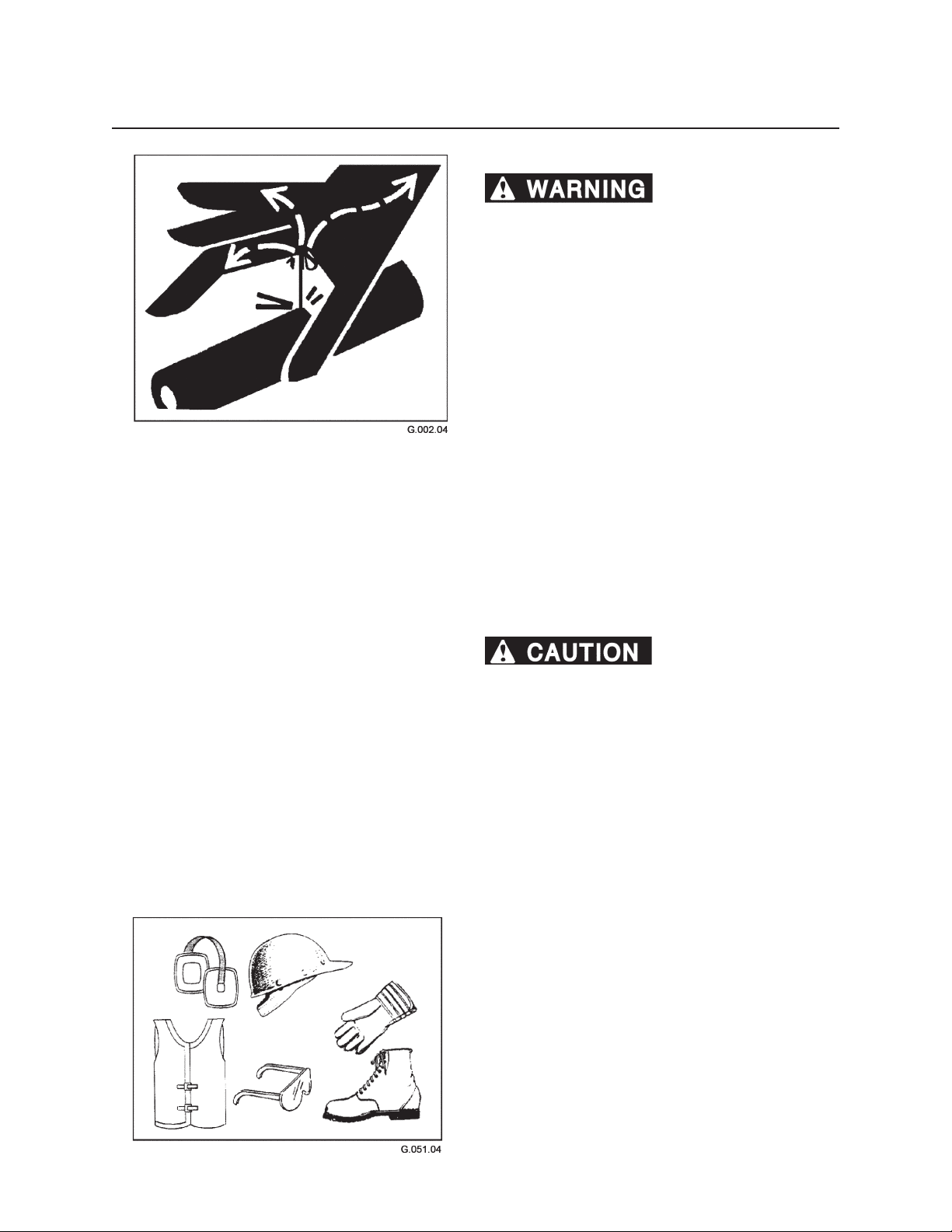
102
Maintenance Safety
HYDRAULIC SAFETY
Fluids escaping under
pressure can penetrate skin and cause severe
personal injury or death. Wear eye and personal
protection equipment (PPE).
If ANY uid is injected into the skin, seek
medical attention immediately. A serious
infection or reaction can result without proper medical
treatment.
Before working on the hydraulic system,
1. Lower boom and grapple to the ground.
2. Raise stabilizers so loader rests on carrier tires.
Then lower stabilizers to they touch the ground
without raising the loader.
3. Shut engine down.
4. Move joysticks in all directions to relieve hydraulic
pressure on boom.
5. Disengage pilot controls by moving pilot shut o
lever UP.
6. Remove key from ignition switch.
7. Purge air from hydraulic reservoir by depressing
relief valve button.
Hot hydraulic oil can cause
severe burns. DO NOT work on hydraulic system if oil
temperature exceeds 120°F (49°C).
Wear eye and personal protection equipment
(PPE)!
Always use a board or cardboard when checking oil
hoses, lines, and ttings periodically for leaks, cracks or
defects. Be sure all clamps are in their proper position
and torqued as required and specied. Be sure hoses
are not twisted or touching parts.
PROTECTIVE CLOTHING
Wear OHSA-approved protective clothing when working on or near this machine, such as
• ear protection • gloves
• goggles • hard hat
• orange vest • steel-toed boots
Wear snug, protective clothing that is belted where
required.
Remove jewelry before working on or near this machine.
Page 61
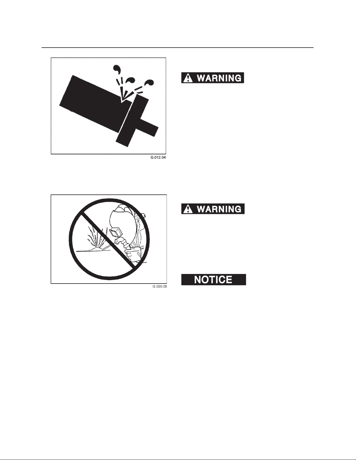
103
Maintenance Safety
SERVICING CONTROL VALVES, CYLINDERS,
PUMPS, AND MOTORS
Increasing relief valve
settings could cause machine or component failure
resulting in severe personal injury or death. Do not
change pressure settings. Do not switch lines from
one valve to another.
Wear eye and personal protection equipment
(PPE)!
Special tools and training are required to service control valves, cylinders, pumps, and motors. If these parts
need service, see an authorized dealer.
UNAUTHORIZED WELDING
Unauthorized welding
can cause structural failure and/or severe personal
injury or death.
DO NOT weld on any structural member.
Any unauthorized welding or repair will void
the warranty.
Once authorized, be sure to turn battery disconnect
master switch OFF.
Unauthorized welding can
cause damage to the electrical system
Page 62
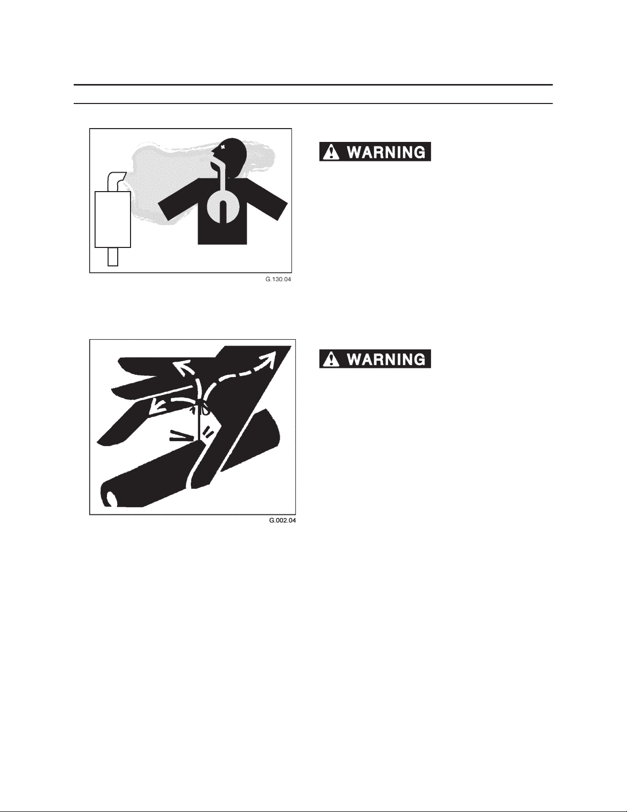
104
Maintenance Safety
DURING MAINTENANCE
DIESEL EXHAUST
Diesel exhaust fumes
contain elements that are hazardous to health.
Always run engine in a well ventilated area. If in an
enclosed area, vent exhaust outside.
FLUIDS UNDER PRESSURE
Fluids escaping under
pressure can penetrate skin and cause severe personal injury or death.
Wear eye and personal protection equipment
(PPE)!
Always use a board or cardboard when checking oil
hoses, lines, and ttings periodically for leaks, cracks,
or defects. Be sure all clamps are in their proper position and torqued as required and specied. Be sure
hoses are not twisted or touching parts.
DO NOT use hands to search for leaks. Escaping uids
can penetrate skin and enter the bloodstream. Before
disconnecting lines, relieve all pressure.
DO NOT apply pressure to a damaged line, hose, or
tting.
If any uid is injected into the skin, seek medical attention immediately. A serious infection or reaction can
result without proper medical treatment.
Page 63
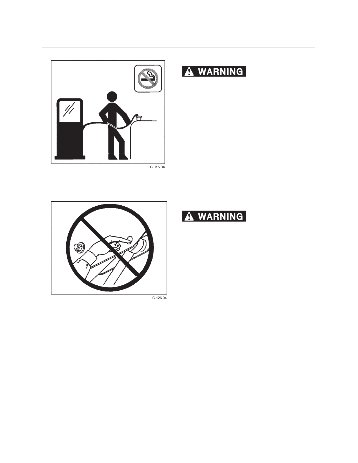
105
Maintenance Safety
FUELS AND LUBRICANTS
Fires and explosions can
cause severe personal injury or death.
• Handle fuels and lubricants carefully.
• DO NOT smoke when fueling or working with or
around fuel.
• Clean up, and properly dispose of all spilled lubri-
cants, grease and solvents.
• Use proper tools and procedures for making
repairs.
• Wear approved eye and personal protection
equipment (PPE).
PINCH POINTS
Placing hands or any
portion of the body where the machine moves can
cause severe personal injury or death. Never place
hands or any portion of the body where injury
could occur if machine moves. Never check pin hole
alignments with ngers.
Page 64
106
Maintenance Safety
AFTER MAINTENANCE
DISPOSING OF WASTE
Follow local, state, federal, and international regulations when disposing of waste. Waste may include, but
is not limited to oil, fuel, coolant, brake uid, lters,
and batteries.
Use leakproof containers when draining uids. Do not
use food or beverage containers. Do not pour waste
on the ground, down a drain, or into any water source.
Clean up all spilled fuel, oil, grease, etc. and dispose of
per local, state, federal, or international regulations.
STORING FLAMMABLE MATERIALS
• Do not smoke where ammable materials are
stored.
• Store fuels and lubricants in properly marked
containers.
• Store oily rags and other ammable materials in
protective containers.
Page 65
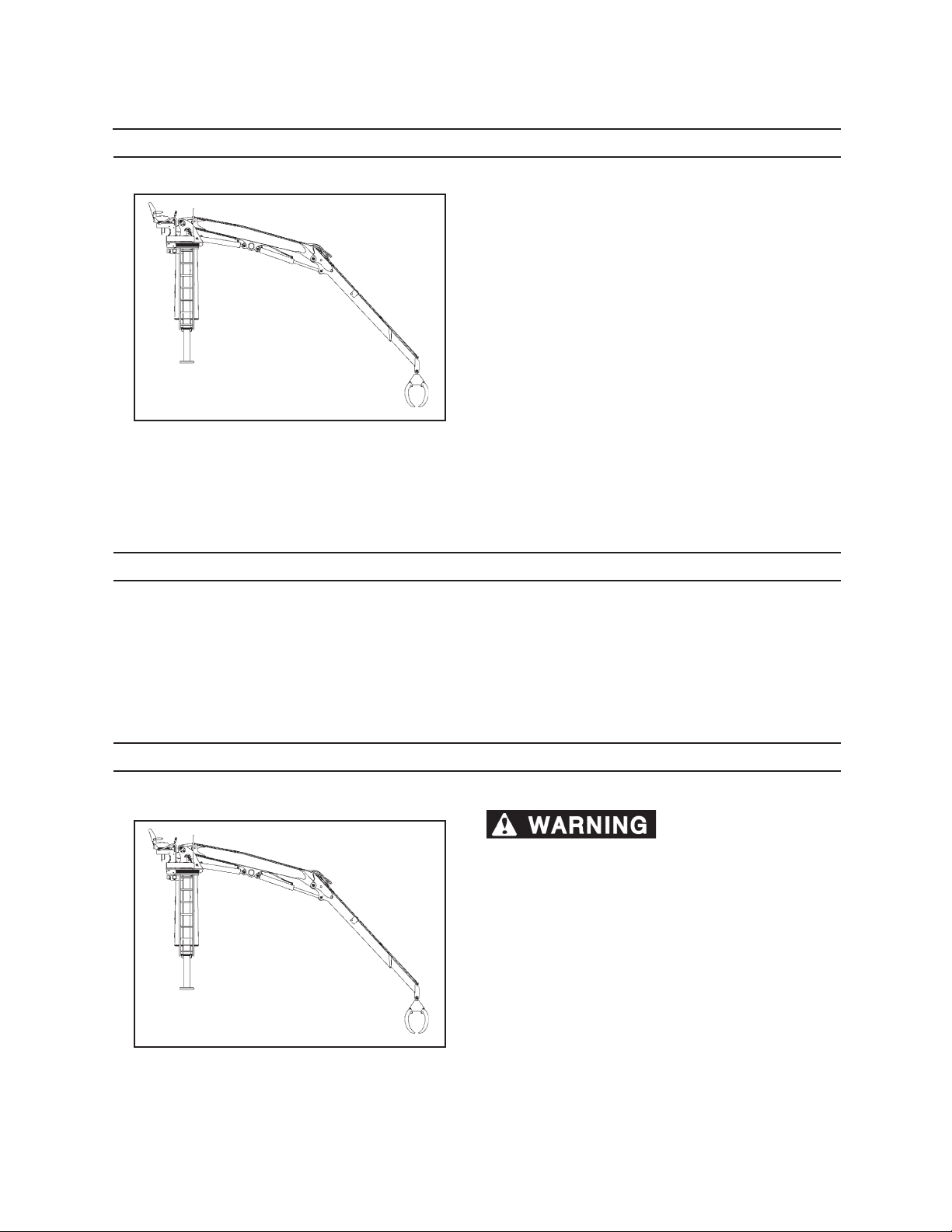
Scheduled & Periodic Maintenance
LUBRICATION AND MAINTENANCE INTERVALS
Maintenance requirements for lubrication, adjustments and checks are shown on the maintenance
charts in this section.
Intervals of maintenance are based on normal operating conditions. If operating under more demanding
conditions, observe a shorter time interval between
maintenance.
Demanding conditions include but are not limited to:
• Frequent handling of near maximum capacity
loads
• High duty cycle operation
• Dry work area with heavy blowing dust
• Extreme cold, -20°F (-6°C) and below
• Extreme heat, 90°F (32°C) and above
111
• Multiple shift operation
LUBRICATION NOTICE
Listed maintenance intervals are for normal use applications. When greasing lubrication ttings, if grease is not forced
out the bushing ends with the recommended shots, increase number of shots used until grease is forced out. If grease
cannot be forced out, check for blocked grease passageways.
If the lubricating areas are dry at the end of a normal operating day, increase the frequency of lubricating time periods
instead of increasing the amount of grease used at one lubrication period.
POSITION MACHINE FOR MAINTENANCE
To avoid serious personal
injury or property damage, follow the steps below
before performing any maintenance on this
machine.
1. Park machine on level ground.
2. Lower boom and grapple to ground.
3. Raise stabilizers so loader rests on carrier tires.
Then lower stabilizers so they touch the ground
without raising the loader.
4. Shut truck engine down.
5. Remove key from ignition switch.
6. Move joysticks in all directions to relieve hydraulic
pressure on boom.
Page 66
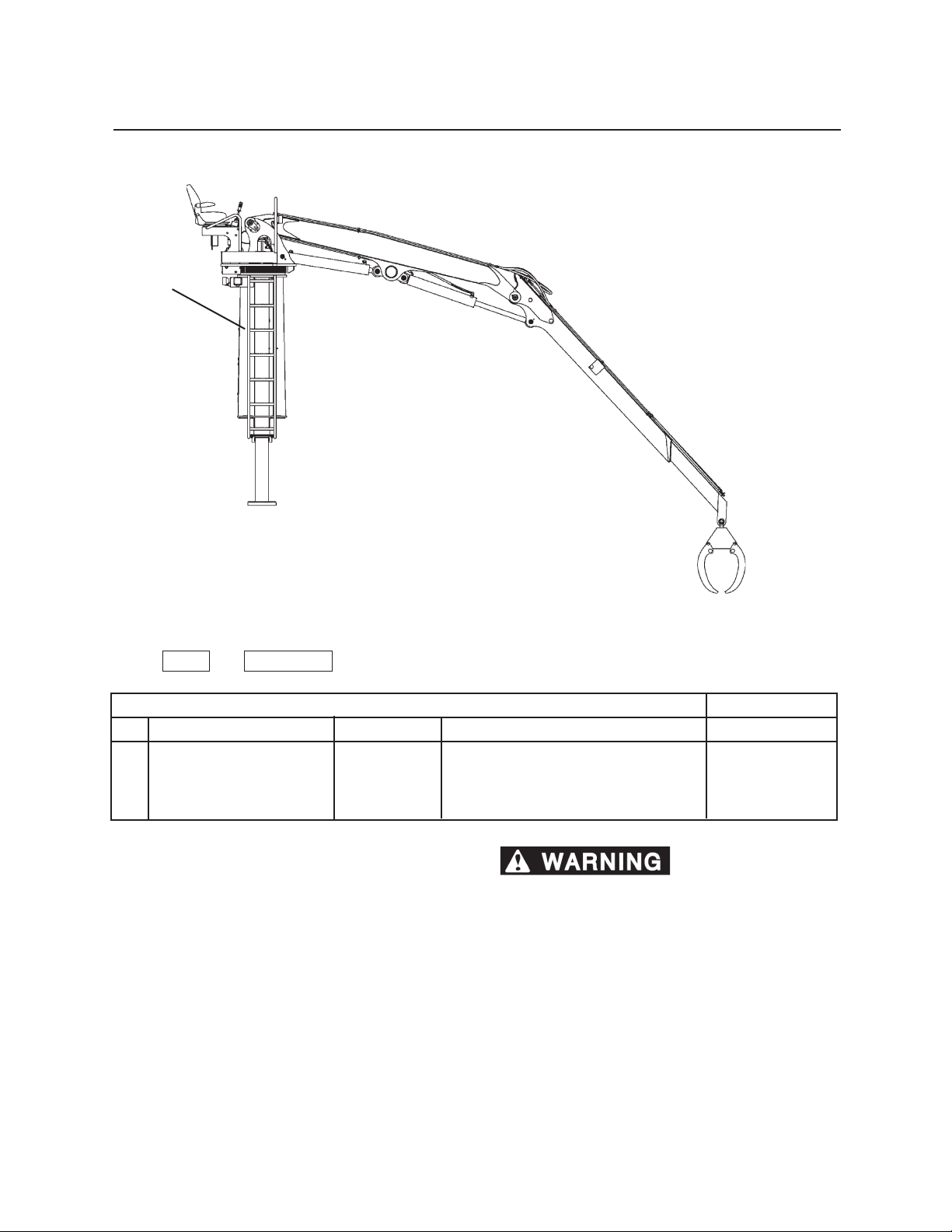
112
Sheduled & Periodic Maintenance
4
MAINTENANCE CHART USAGE
Use the KEY # and COMPONENT for locating the proper service and maintenance procedures in this section.
AS REQUIRED
KEY COMPONENT SERVICE SPECIFICATION
1. Electrical System* Check Inspect harness and connections
2. Hydraulic Oil* Drain/replace Seasonally AS Hyd. Oil
3. Safety Decals* Clean Replace Use only genuine parts
4. Ladder Check Inspect ladder structure and fasteners Use only genuine parts
* - Not shown
** Do not alter A-Frame
MATERIAL USED
structure. Do not weld or machine A-Frame
structure. Immediately report structural problems
(cracks and/or bends) to an authorized dealer for
diagnosis and repair or replacement.
Page 67
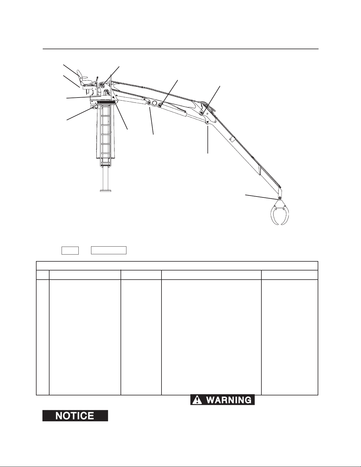
113
Scheduled & Periodic Maintenance
17
16
12
13
6
10
9
7
8
11
5
MAINTENANCE CHART USAGE
Use the KEY # and COMPONENT for locating the proper service and maintenance procedures in this section.
DAILY OR EVERY 10 HOURS
KEY COMPONENT SERVICE SPECIFICATION
*DAILY VISUAL INSPECTION** Inspect Inspect loader for damage, see detail
5. Adapter Knuckle Lubricate Lubricate until grease is forced out Prem. Grease
6. Main Boom Pivot Pin Lubricate Lubricate until grease is forced out Prem. Grease
7. Main Boom Cylinder Base End Lubricate Lubricate until grease is forced out Prem. Grease
8. Main Boom Cylinder Rod End Lubricate Lubricate until grease is forced out Prem. Grease
9. Main/Stick Pivot Pin Lubricate Lubricate until grease is forced out Prem. Grease
10. Stick Boom Cylinder Base End Lubricate Lubricate until grease is forced out Prem. Grease
11. Stick Boom Cylinder Rod End Lubricate Lubricate until grease is forced out Prem. Grease
12. Swing Bearing Lubricate Lubricate while rotating 2 complete Prem. Grease
revolutions
13. Pinion Gear Lubricate Lubricate gear with open gear lube Open gear lube
14. Hydraulic Oil Reservoir* Check level Add hydraulic oil if necessary Hyd. Oil
15. Electrical Components* Inspect Check for fraying, loose connections See details in section
16. Seat Fasteners Check/replace Tighten. Replace if missing. Wrench
17. Seat belt (optional) Inspect Replace if damaged Use genuine parts
* - Not shown
Lubricate with Premium
Moly-Lith EP #2 Grease.
** Do not alter A-Frame
structure. Do not weld or machine A-Frame structure.
Immediately report structural problems (cracks and/or
bends) to an authorized dealer for diagnosis and
repair or replacement.
MATERIAL USED
Page 68
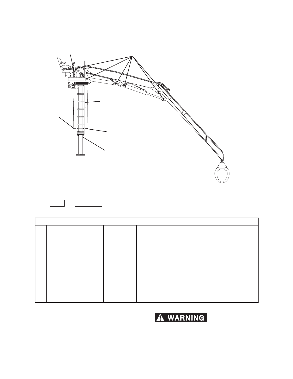
114
Sheduled & Periodic Maintenance
18
24
19
26
20
25
MAINTENANCE CHART USAGE
Use the KEY # and COMPONENT for locating the proper service and maintenance procedures in this section.
WEEKLY OR EVERY 50 HOURS
KEY COMPONENT SERVICE SPECIFICATION
*. WEEKLY INSPECTION Inspect Check for damage, see detail
18. Loader Mounting Bolts Inspect Check for stability of loader position
19. Boom / Cylinder Pin Retainers Check Snap rings in place. Replace if missing. Use genuine parts
20. Stabilizer Cylinder Pins Check Snap rings in place. Replace if missing. Use genuine parts
21. Oil Reservoir Hardware* Check Tighten Wrench
22. Hydraulic connections* Inspect Tighten Wrench
23. Hydraulic Oil Reservoir* Check oil If contaminated, replace Prem AS
Hyd Oil
24. Joystick boots Inspect
25. Stabillizer Cylinder Rod End Lubricate Lubricate until grease is forced out Prem. Grease
26. Stabilizer Cylinder Base End Lubricate Lubricate until grease is forced out Prem. Grease
* - Not shown
Check for cracks and damage. Replace if damaged.
** Do not alter A-Frame
MATERIAL USED
Use genuine parts
structure. Do not weld or machine A-Frame
structure. Immediately report structural problems
(cracks and/or bends) to an authorized dealer for
diagnosis and repair or replacement.
Page 69
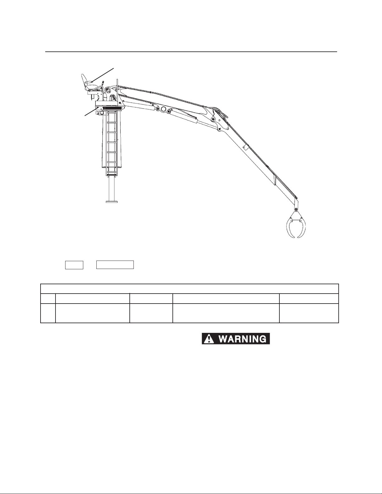
28
115
Scheduled & Periodic Maintenance
27
MAINTENANCE CHART USAGE
Use the KEY # and COMPONENT for locating the proper service and maintenance procedures in this section.
MONTHLY OR EVERY 250 HOURS
KEY COMPONENT SERVICE SPECIFICATION
27. Seat Inspect/Lube Lubricate seat position adjustment Silicone spray
28. Swing Drive Fasteners Check Tighten to 160 ft-lbs (218 N•m) Torque wrench
** Do not alter A-Frame
structure. Do not weld or machine A-Frame
structure. Immediately report structural problems
(cracks and/or bends) to an authorized dealer for
diagnosis and repair or replacement.
MATERIAL USED
Page 70
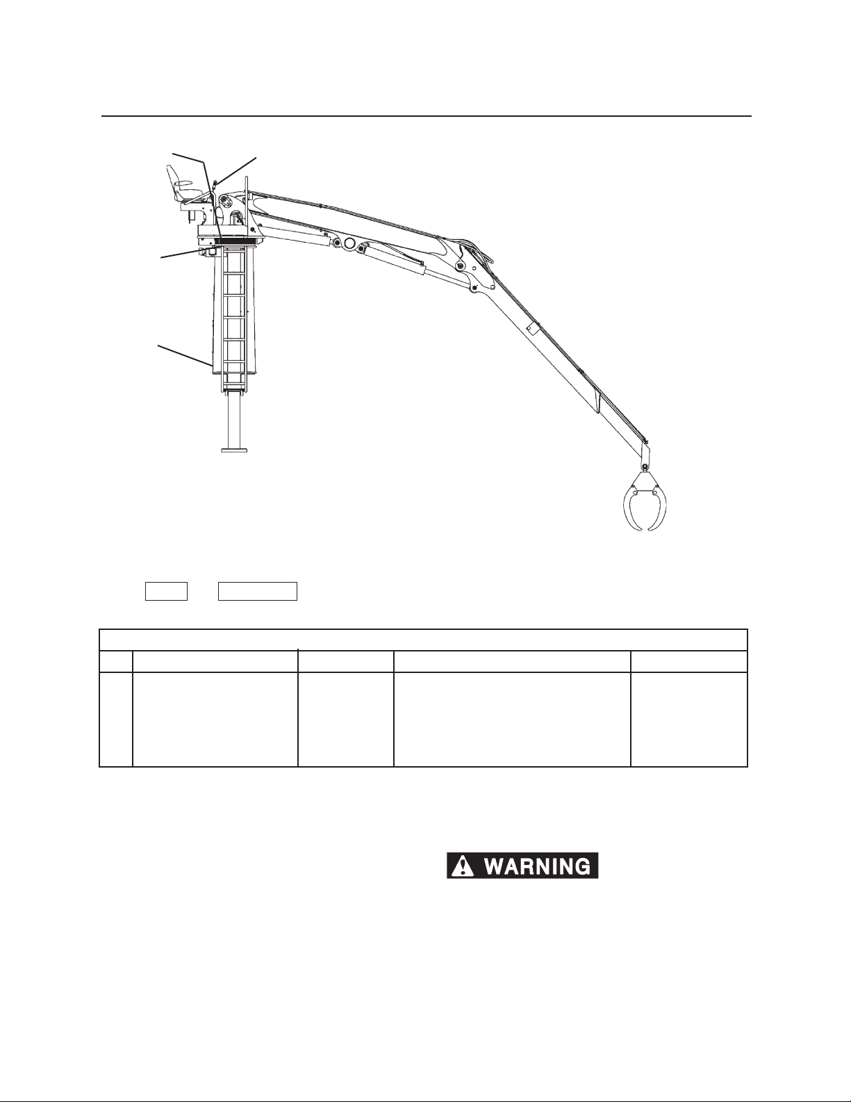
116
Sheduled & Periodic Maintenance
32
29
30
31
33
MAINTENANCE CHART USAGE
Use the KEY # and COMPONENT for locating the proper service and maintenance procedures in this section.
EVERY THREE MONTHS OR 600 HOURS
KEY COMPONENT SERVICE SPECIFICATION
29. Hydraulic Oil Return Line Filter Install new* Replacement lter Use genuine parts
30. Return/Case Drain Filter Install new* New lter Use genuine parts
31. Outer Swing Bearing Fasteners Check Tighten to 360 ft-lbs (490 N•m) Torque wrench
32. Inner Swing Bearing Fasteners Check Tighten to 730 ft-lbs (993 N•m) Torque wrench
33. Joystick Lubricate Grease ttings beneath joystick boot Prem. Grease
* - Change interval can vary depending on operating conditions
** Do not alter A-Frame
structure. Do not weld or machine A-Frame
structure. Immediately report structural problems
(cracks and/or bends) to an authorized dealer for
diagnosis and repair or replacement.
MATERIAL USED
Page 71
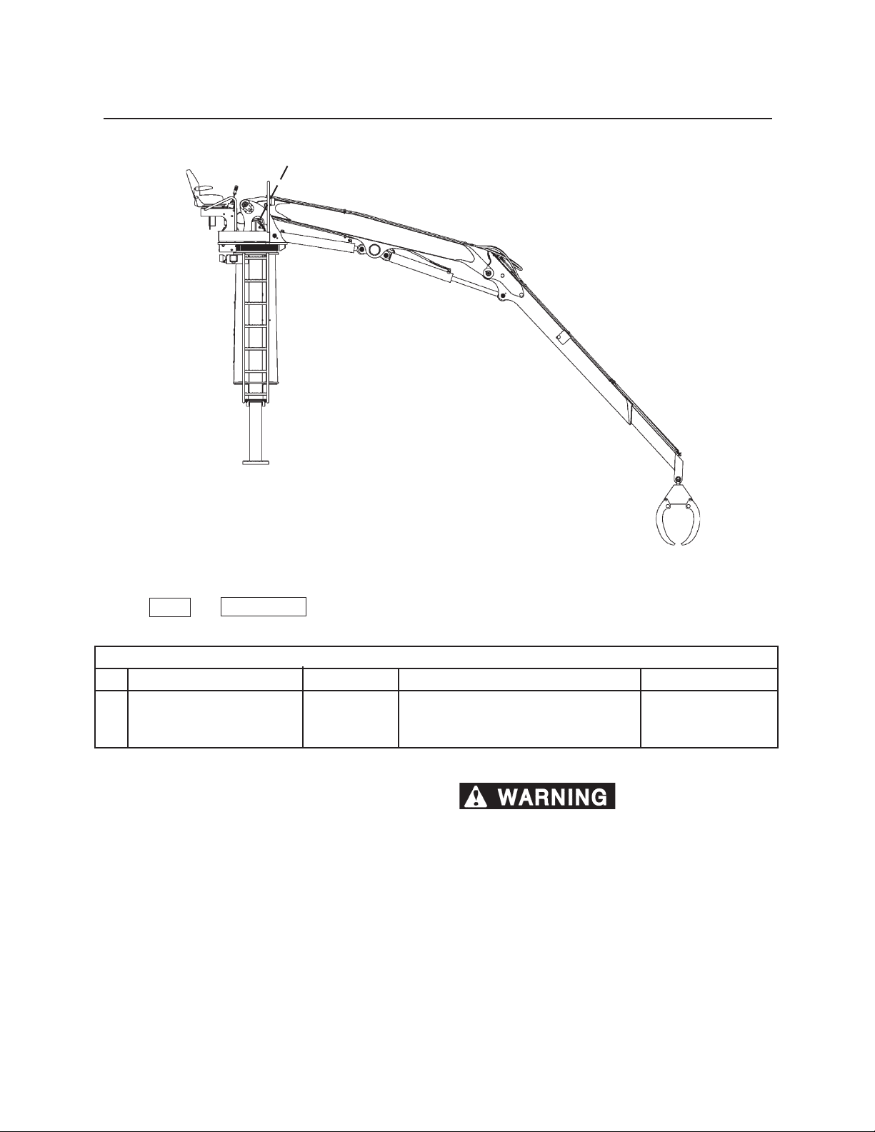
35
117
Scheduled & Periodic Maintenance
MAINTENANCE CHART USAGE
Use the KEY # and COMPONENT for locating the proper service and maintenance procedures in this section.
EVERY SIX MONTHS OR 1200 HOURS
KEY COMPONENT SERVICE SPECIFICATION
34. Hydraulic Oil* Drain/replace See details in section Premium AS Oil
35. Collector Ring Check/clean Spray contacts, check brushes and wire Contact cleaner
connections
MATERIAL USED
* - Not shown
** Do not alter A-Frame
structure. Do not weld or machine A-Frame
structure. Immediately report structural problems
(cracks and/or bends) to an authorized dealer for
diagnosis and repair or replacement.
Page 72
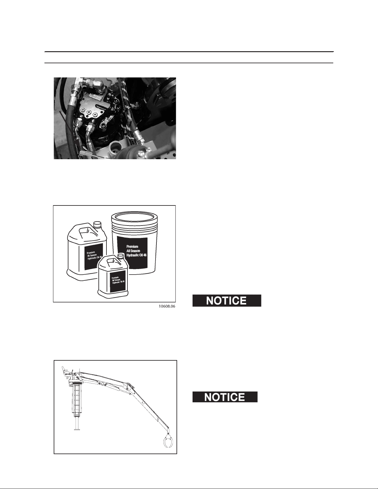
118
Sheduled & Periodic Maintenance
AS REQUIRED
1. CHECK ELECTRICAL SYSTEM
Check all electrical wires daily. Wiring must be kept in
good condition. All electrical wires must be properly
routed and securely attached. Repair any wires that are
loose or frayed before starting the engine. Clean and
tighten all electrical connections.
Arcing or sparking could cause a re. Securing connections and maintaining recommended wiring will help
to prevent arcing or sparking.
If electrical problems occur, check wire harness and
connectors.
2. DRAIN AND REPLACE HYDRAULIC OIL
Hydraulic oil must be changed based on the ambient
(outside) air temperature. Certain grades of hydraulic
oil work best in certain temperature ranges.
Follow Caterpillar Forest Product’s hydraulic oil specications. If oil is not changed seasonally, as required,
the hydraulic system can be damaged.
Refer to Lubricants section for hydraulic oil recommendations.
Hydraulic oil capacity is 42 gallons (160 L)
DO NOT mismatch brands or
weights of hydraulic oil.
3. INSPECT SAFETY DECALS
Inspect safety decals and replace as needed when
damaged or unreadable.
Decals will not adhere to
dirty or wet surfaces. Thoroughly clean and dry any area
where a decal or slip resistant mat is to be placed.
Page 73
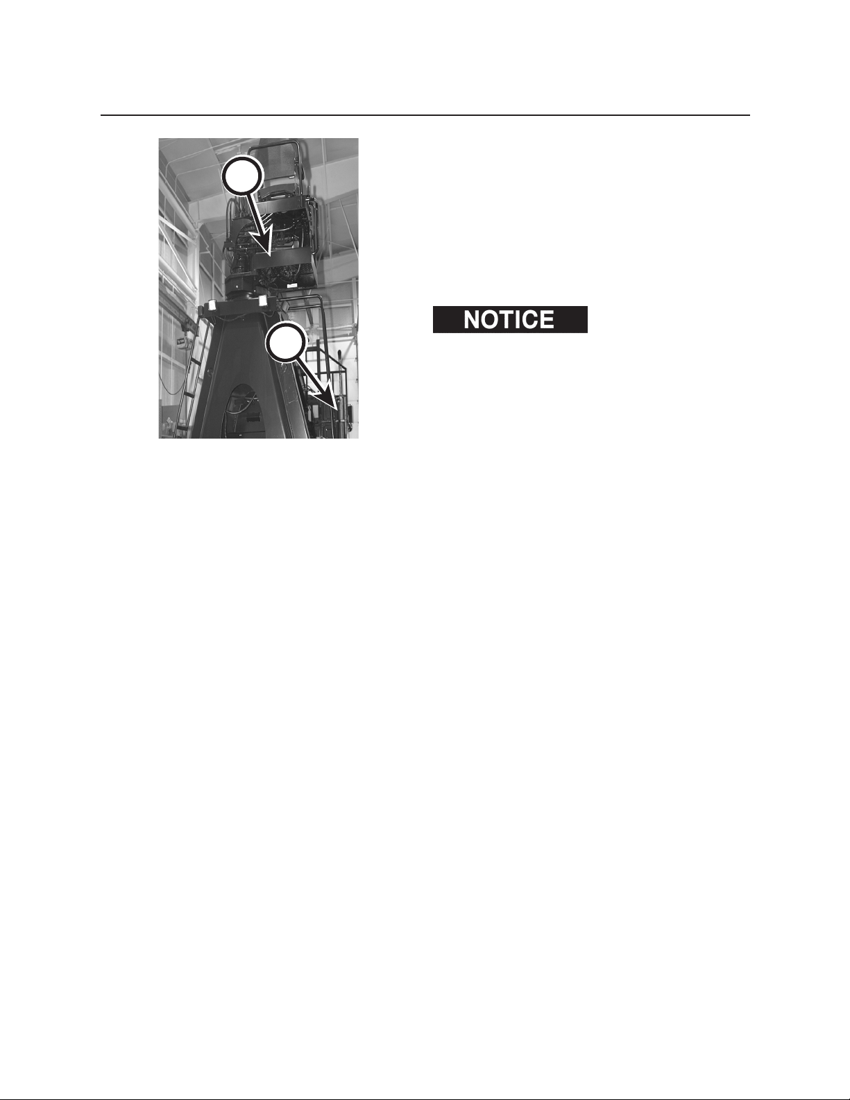
A
B
119
Scheduled & Periodic Maintenance
4. INSPECT LADDER STRUCTURE AND
FASTENERS
Check that the upper ladder mounting fasteners (A)
are torqued at 266-294 ft-lbs (361-399 N•m) torque.
Check that the lower ladder mounting fasteners (B) are
torqued at 76-84 ft-lbs
(103-114 N•m) torque.
If damaged or missing, replace with new.
Caterpillar Forest Products
engineering does not approve installation of a 90 degree
ladder on the service side of the loader. Do not congure
machine with two 90 degree ladders.
Page 74
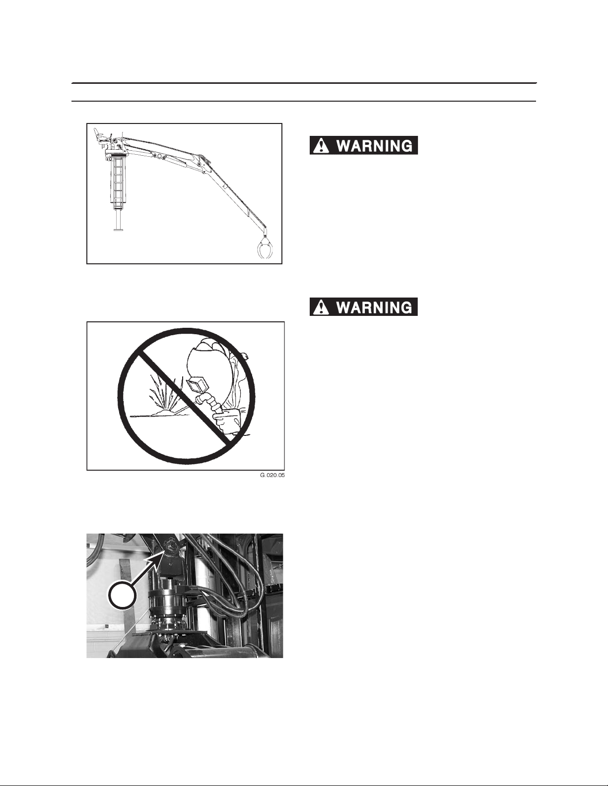
1110
Sheduled & Periodic Maintenance
DAILY OR EVERY 10 HOURS
PERFORM A DAILY VISUAL INSPECTION
Failure to perform a
daily inspection of machine can result in machine
damage and severe personal injury or death.
In addition to the required daily inspection outlined in
Pre-Start Inspection section perform a daily inspection
of the following components:
• Structures • Swing bearing
• Booms • Load-bearing items
• Cylinders • All mountings
• Turntable
Unauthorized welding
can cause structural failure and/or severe personal
injury or death.
A
DO NOT weld on any structural member.
Any unauthorized welding or repair will void
the warranty.
Once authorized, be sure to turn battery disconnect
master switch OFF.
5. LUBRICATE ADAPTER KNUCKLE
Lubricate adapter knuckle (A) with Premium Moly-Lith
EP #2 until grease is forced out.
Page 75
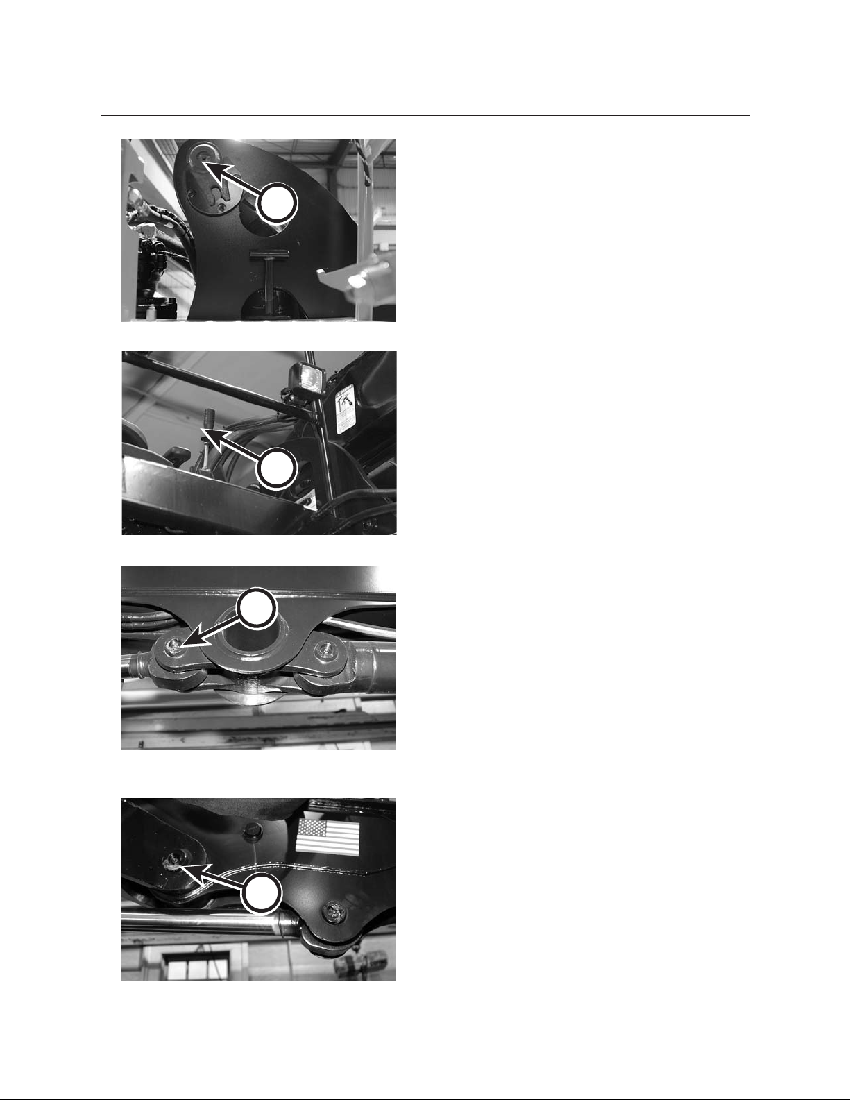
A
1111
Scheduled & Periodic Maintenance
6. LUBRICATE MAIN BOOM PIVOT PIN
Lubricate main boom pivot pin (A) with Premium
Moly-Lith EP #2 until grease is forced out.
7. LUBRICATE MAIN BOOM CYLINDER
BASE ENDS
Lubricate main boom cylinder base ends (B) with Premium Moly-Lith EP #2 until grease is forced out.
C
B
8. LUBRICATE MAIN BOOM CYLINDER
ROD ENDS
Lubricate main boom cylinder rod ends (C) with Premium Moly-Lith EP #2 until grease is forced out.
9. LUBRICATE MAIN/STICK PIVOT PIN
Lubricate main/stick pivot pin (D) with Premium MolyLith EP #2 until grease is forced out.
D
Page 76
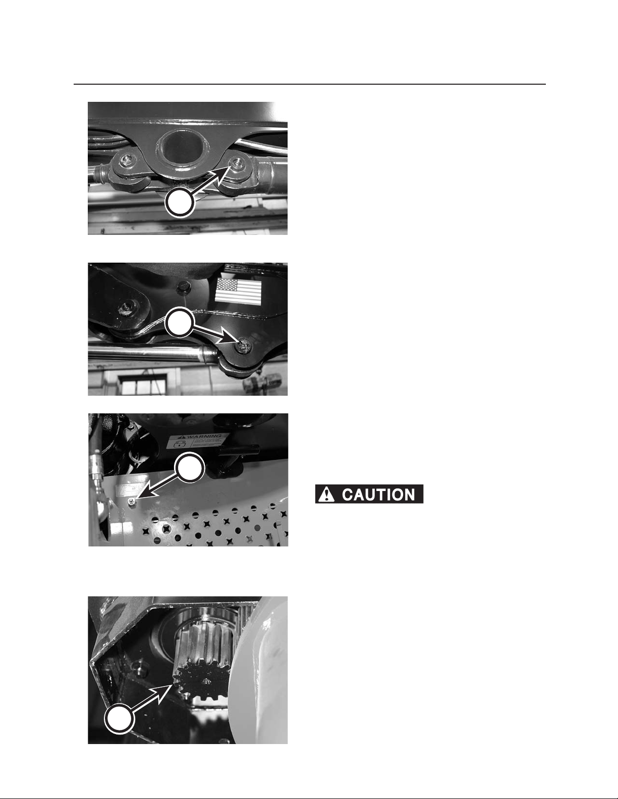
1112
Sheduled & Periodic Maintenance
A
B
10. LUBRICATE STICK BOOM CYLINDER
BASE END
Lubricate stick boom cylinder base end (A) with Premium Moly-Lith EP #2 until grease is forced out.
11. LUBRICATE STICK BOOM CYLINDER
ROD END
Lubricate stick boom cylinder rod end (B) with Premium Moly-Lith EP #2 until grease is forced out.
C
12. LUBRICATE SWING BEARING
The swing bearing grease tting (C) is located left of
the operator’s seat, near the transit lock.
Lubricate swing bearing with Premium Moly-Lith
EP #2 while rotating loader 2 complete revoluti
ns.
Rotate turntable slowly. Boom can strike people
or property, which can cause personal injury
or property damage. Be sure loader is clear of
obstructions, remove personnel, and make sure
those not performing maintenance are clear of the
machine.
13. LUBRICATE PINION GEAR
Coat pinion gear teeth (D) with Heavy Duty Open Gear
Lube to prevent bare metal contact.
D
Page 77
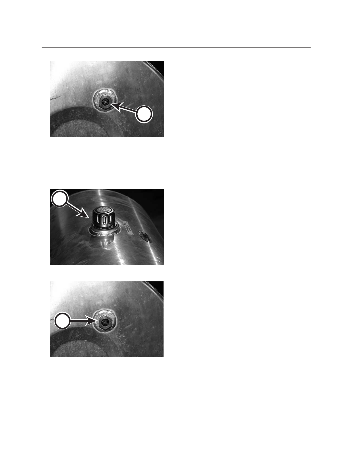
A
1113
Scheduled & Periodic Maintenance
14. CHECK HYDRAULIC OIL RESERVOIR
LEVEL
1. Position loader properly for an accurate reading.
Booms should be in transport position and stabilizers should be raised.
2. Move joysticks in all directions to relieve hydraulic
pressure.
3. Visually check the oil level by observing the sight
gauge (A) on the hydraulic reservoir while oil is
warm. Sight gauge is located on hydraulic tank.
4. Add clean, ltered oil, if necessary (see instruc-
tions below).
B
FILLING HYDRAULIC RESERVOIR
1. Clean area around ller cap (B).
2. Remove ller cap.
3. Insert clean hose into oil supply container with
nozzle end in hydraulic oil reservoir.
4. Fill reservoir until oil reaches the top of the
hydraulic reservoir sight gauge (C). Hydraulic oil
capacity is 42 gallons (159 L).
C
Page 78
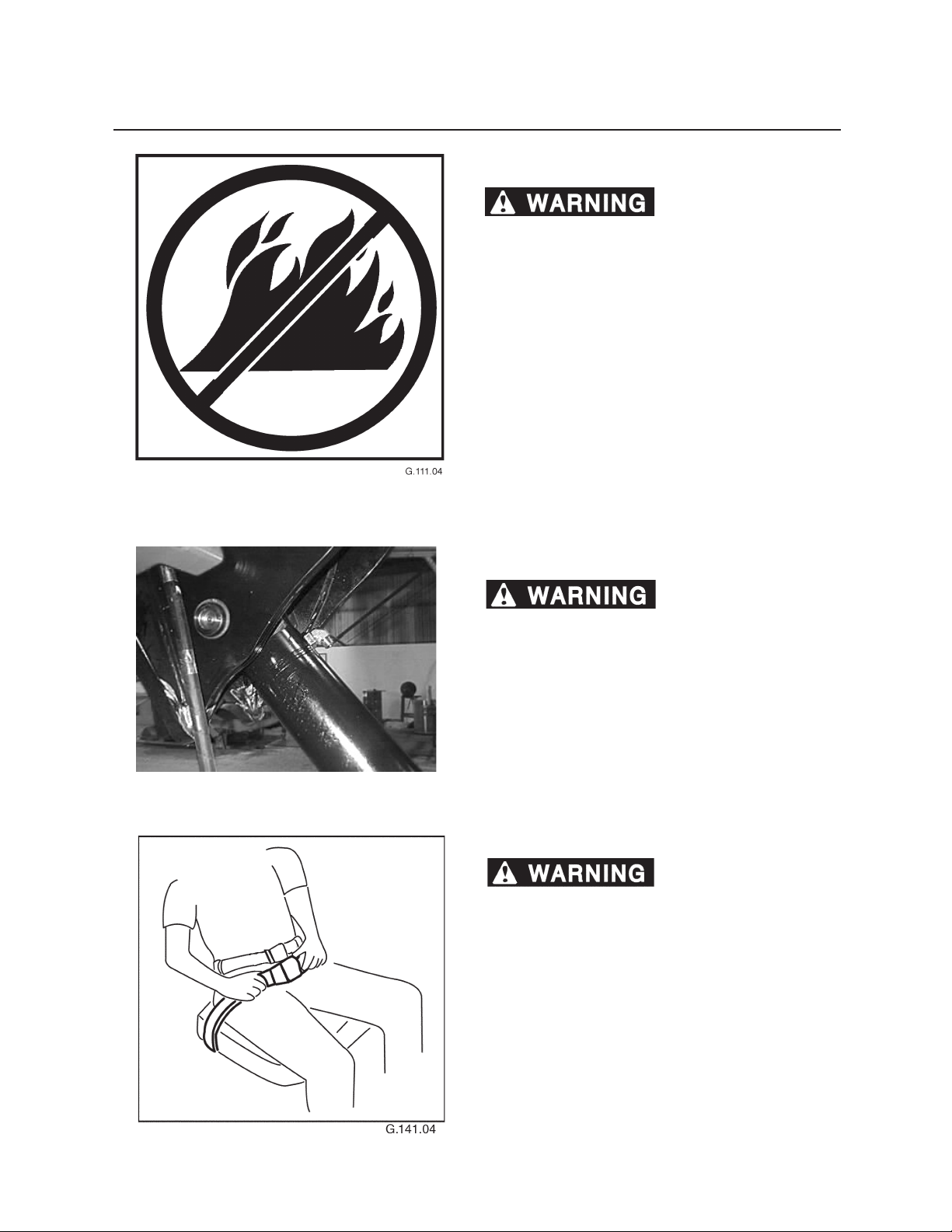
1114
Sheduled & Periodic Maintenance
15. INSPECT ELECTRICAL COMPONENTS
Loose, frayed, or worn
electrical components may result in electrical
shock or re, causing severe personal injury or
death.
Check all electrical wires daily. Wiring must be kept in
good condition. All electrical wires must be properly
routed and securely attached. Repair any wires that are
loose or frayed before starting the engine. Clean and
tighten all electrical connections.
Arcing or sparking could cause a re. Securing connections and maintaining recommended wiring will help
to prevent arcing or sparking.
16. INSPECT SEAT FASTENERS
Loose, broken or dam-
aged fasteners can cause seat to be unstable,
causing severe personal injury or death.
Check all seat fasteners daily. If loose, tighten. If broken, damaged or missing, replace with new fasteners.
Damaged, loose or missing fasteners could cause seat
to be unstable.
17. INSPECT SEAT BELT OPTIONAL
Replace seat belt if any sign
of wear is visible. Failure to replace worn seat belt as
needed can result in serious personal injury or death.
Check seat belt (A) for any sign of wear or fraying. If
any sign of wear is visible, replace seat belt.
Page 79
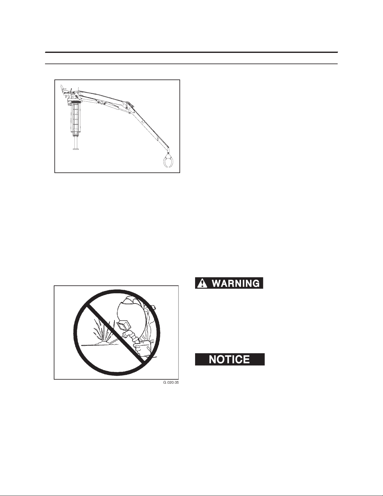
WEEKLY OR EVERY 50 HOURS
PERFORM A WEEKLY INSPECTION USING THE FOL
LOWING GUIDELINES
1. Clean the structure thoroughly. Remove all dirt,
mud, grease, oil, debris, and snow.
2. Look for rust lines in the paint, and missing or
cracked paint. These are indications of crack sites.
3. Inspect all welds and adjacent areas on booms,
cylinders, turntable, swing gear mounting, and
grapple for signs of cracks.
4. Inspect the grapple around cylinder and jaw
mountings, the jaws, the rotator mounting, and
frame.
5. Check all boom cylinders and pin keeper retainers for broken fasteners. If broken or damaged,
replace with new fasteners.
1115
Scheduled & Periodic Maintenance
6. Check the mounting to the truck or trailer frame.
Ensure that the fasteners are tight and any spacers
are in good condition and in their correct locations.
7. Check the sub-frame and stabilizers. Check the
areas around the swing bearing mounting, the
stabilizer, and their mounting ears, and the stabilizer cylinders and their mounting.
Unauthorized welding can
cause structural failure and/or severe personal
injury or death.
DO NOT weld on any structural member.
Any unauthorized welding or repair will void
the warranty.
Once authorized, be sure to turn battery disconnect
master switch OFF.
. Unauthorized welding can
cause damage to the electrical system.
8. Inspect safety decal and replace as needed when
damaged or illegible (unreadable).
Page 80
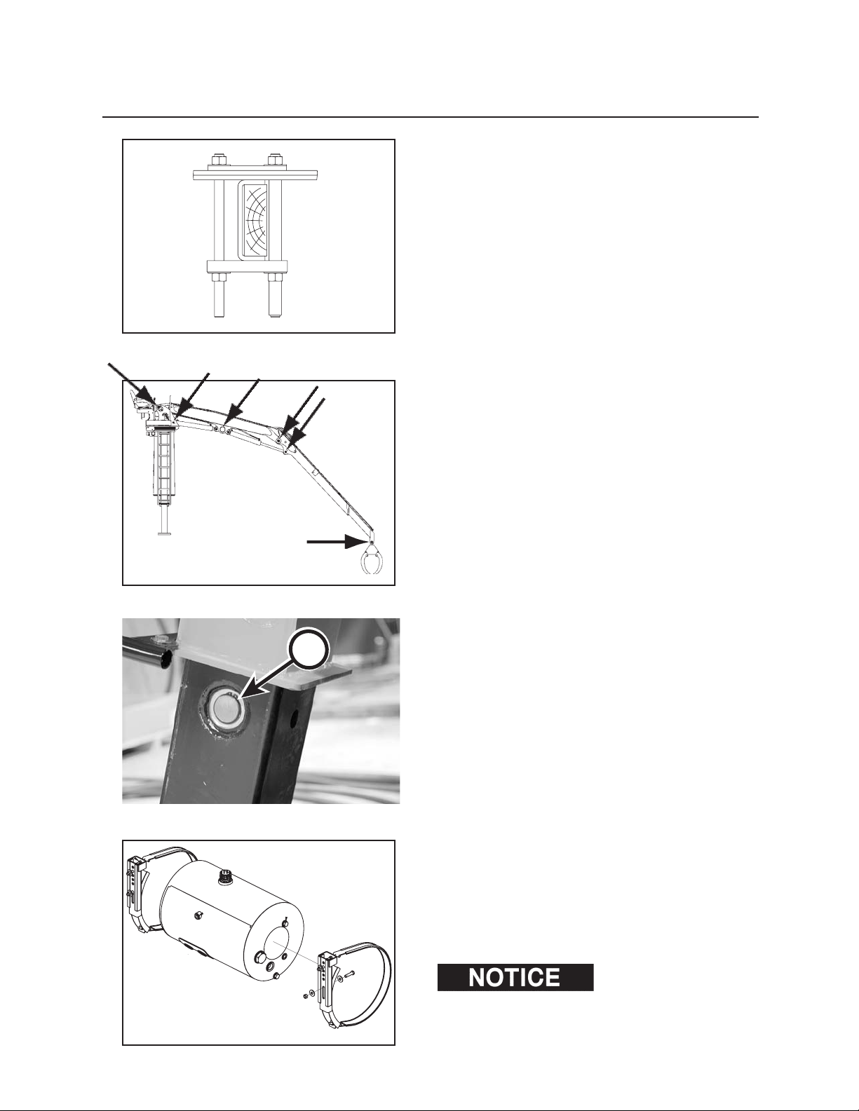
1116
Sheduled & Periodic Maintenance
18. INSPECT LOADER MOUNTING BOLTS
Inspect and tighten loader mounting bolts, ensuring
loader position has not moved.
19. CHECK BOOM AND CYLINDER AT
TACHING PINS
Inspect and tighten all boom and cylinder attaching
pins and pin retaining hardware.
A
20. CHECK STABILIZER ATTACHING PINS
Inspect and tighten all stabilizer attaching pins (A).
Verify that all snap rings are in place and secure.
21. CHECK HYDRAULIC OIL RESERVOIR
HARDWARE
Inspect and tighten hydraulic oil reservoir hardware.
If damaged, replace with new. Torque mounting band
clamp fasteners to 17-19 ft-lbs
(23 - 26 N•m) torque.
Overtightening of fasteners
can result in damage to reservoir.
Page 81
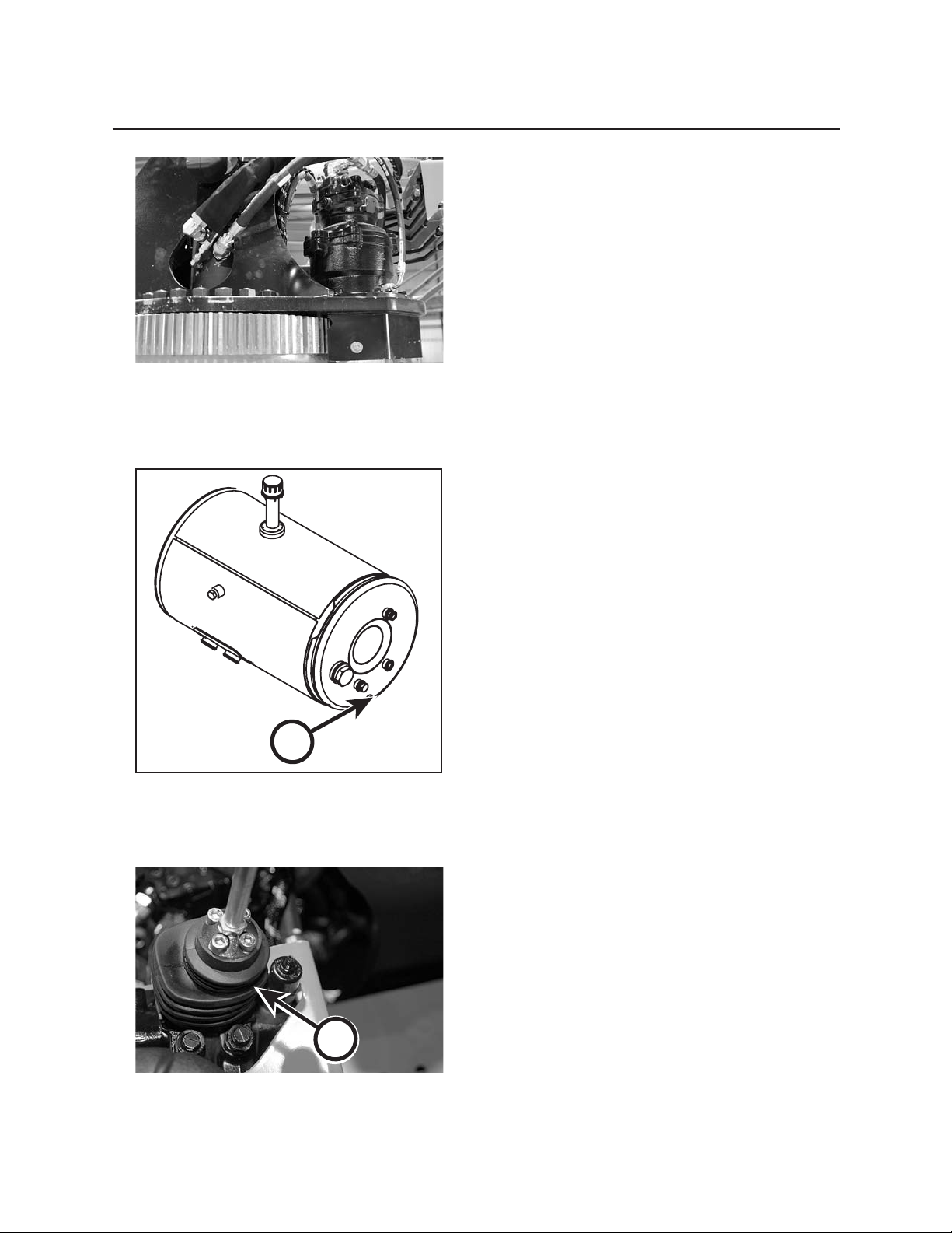
1117
Scheduled & Periodic Maintenance
22. CHECK HYDRAULIC CONNECTIONS
Inspect and tighten all hydraulic connections.
23. CHECK HYDRAULIC OIL RESERVOIR
FOR CONTAMINANTS
A
1. Loosen drain plug (A) on bottom of hydraulic
reservoir.
2. Using a catch pan to collect hydraulic oil, visually
inspect hydraulic oil for contamination.
If contamination such as water is visible, the hy-
draulic oil reservoir must be drained, cleaned, and
lters replaced. For procedures on changing the
hydraulic oil, see Changing Hydraulic Reservoir Oil
in this section.
3. Tighten drain plug.
4. Dispose of used hydraulic oil properly.
24. INSPECT JOYSTICK BOOTS
Inspect joystick boots (B) for cracks, tears, or other
damage that may expose the components beneath
them. Replace joystick boots if damaged.
B
Page 82
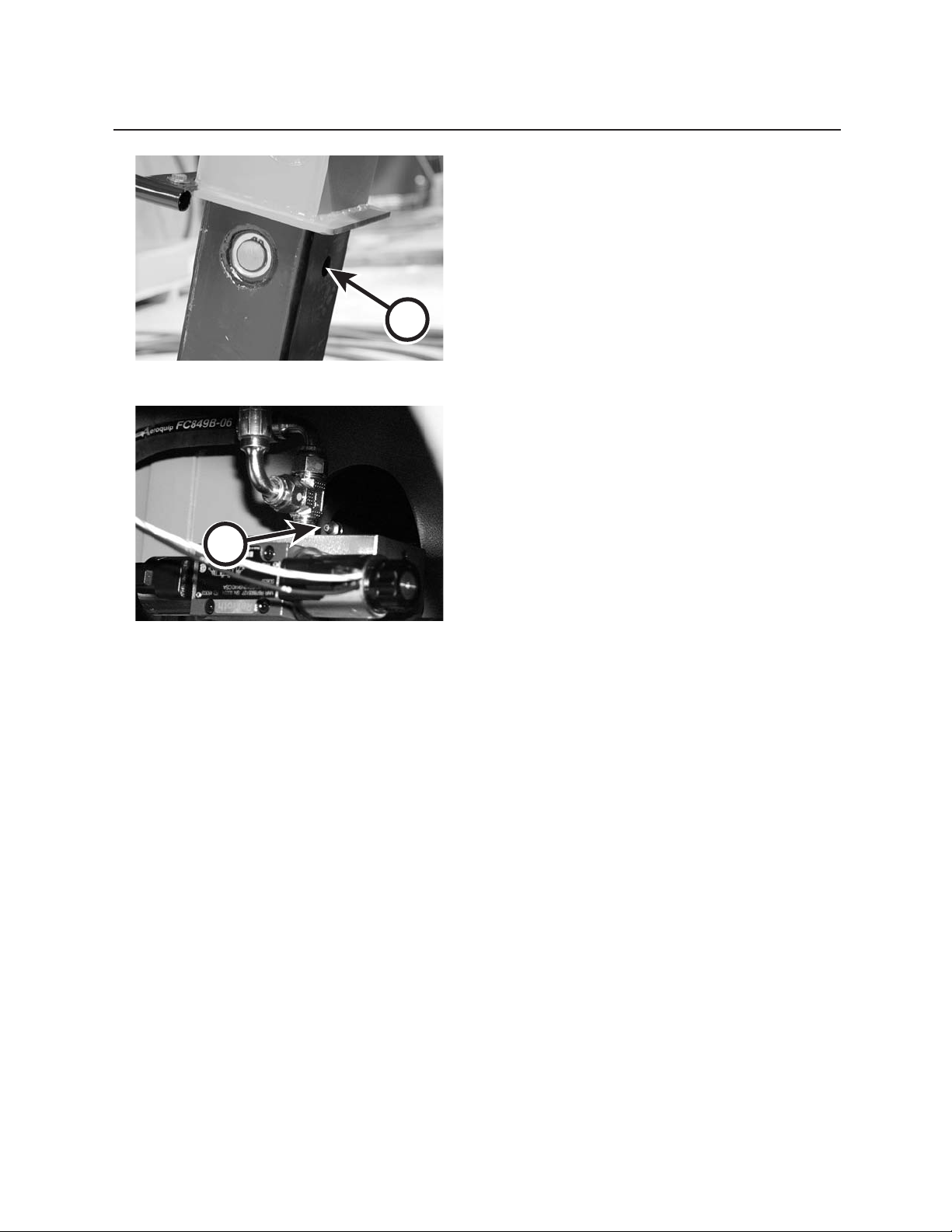
1118
Sheduled & Periodic Maintenance
WEEKLY OR EVERY 50 HOURS
25. LUBRICATE STABILIZER CYLINDER
ROD ENDS
Lubricate stabilizer cylinder rod ends with Premium
Moly-Lith EP #2 until grease is forced out. Grease tting is located inside hole (A).
A
26. LUBRICATE STABILIZER CYLINDER
BASE ENDS
Lubricate stabilizer cylinder base ends (B) with Premium Moly-Lith EP #2 until grease is forced out.
B
Page 83
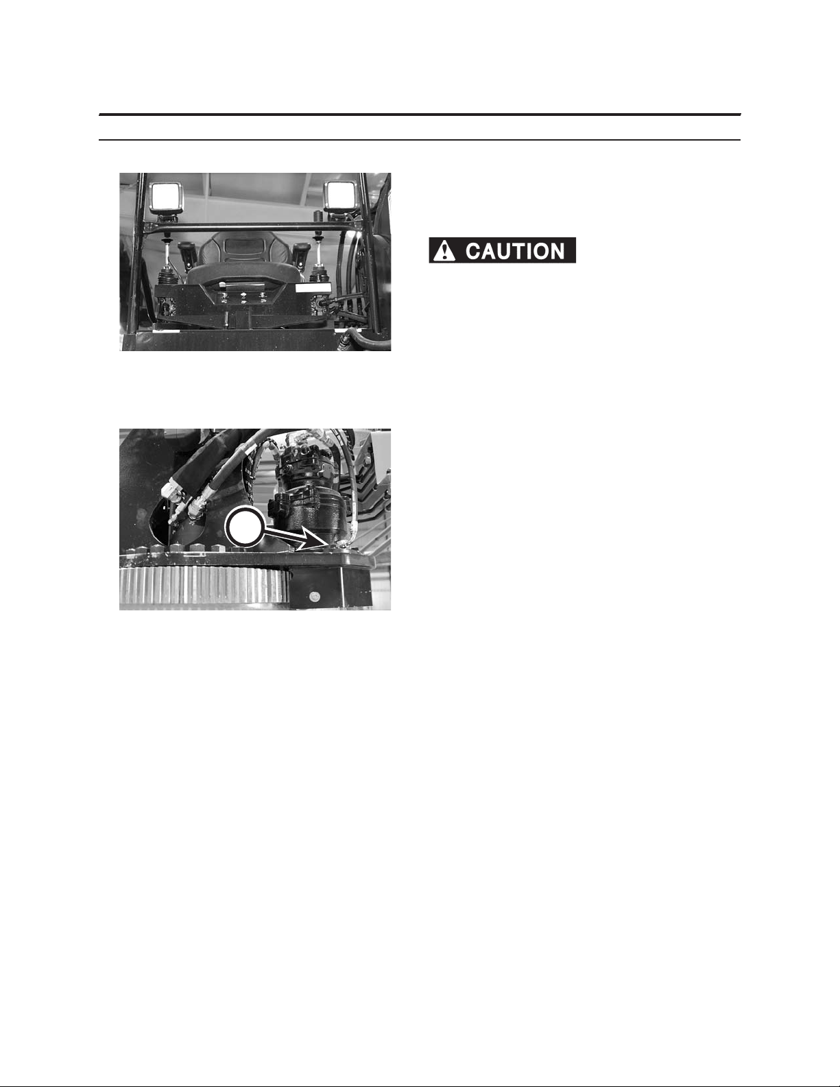
Scheduled & Periodic Maintenance
MONTHLY OR EVERY 250 HOURS
27. PERFORM SEAT MAINTENANCE
1. Inspect all moving and pivoting parts of the seat.
If damaged, replace with new.
and track hardware are secure. Verify tracks and
seat back lock rmly into place. Seat can become
unstable causing serious personal injury or property damage.
2. Lubricate the all of the moving and pivoting parts
as needed.
28. CHECK SWING DRIVE FASTENERS
1119
Verify arm pivot screws
A
Check that the swing drive fasteners (A) are tightened
to 160 ft-lbs (218 N•m) torque.
If fasteners are damaged, replace with new using
threadlock.
Page 84
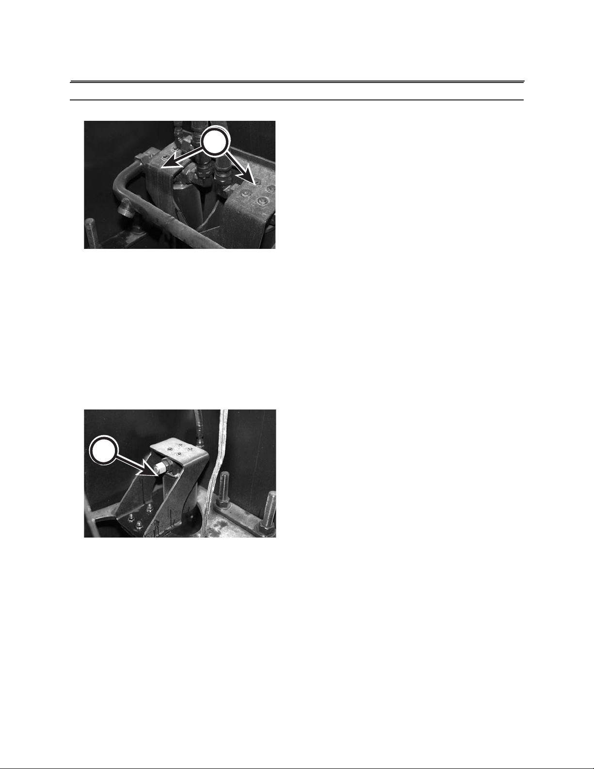
1120
Sheduled & Periodic Maintenance
EVERY THREE MONTHS OR 600 HOURS
A
29. REPLACE HYDRAULIC RETURN LINE
FILTERS
1. Lower boom and grapple to ground. Shut engine
down and remove key.
2. Move joysticks in all directions to relieve hydraulic
pressure.
3. Open reservoir ller/breather to release reservoir
pressure.
4. Remove hydraulic oil lters (A).
5. Fill new lters with hydraulic oil.
6. Lubricate gasket with new hydraulic oil.
7. Install new lters.
8. Run at idle speed for 5 minutes. Check for leakage
around lter gaskets.
B
9. Dispose of used lters properly.
30. REPLACE CASE DRAIN FILTER
1. Lower boom and grapple to ground. Shut engine
down and remove key.
2. Move joysticks in all directions to relieve hydraulic
pressure.
3. Open reservoir ller/breather to release reservoir
pressure.
4. Remove case drain lter (A).
5. Fill new lter with hydraulic oil.
6. Lubricate gasket with new hydraulic oil.
7. Install new lter.
8. Run at idle speed for 5 minutes. Check for leakage
around lter gasket.
9. Dispose of used lter properly.
Page 85
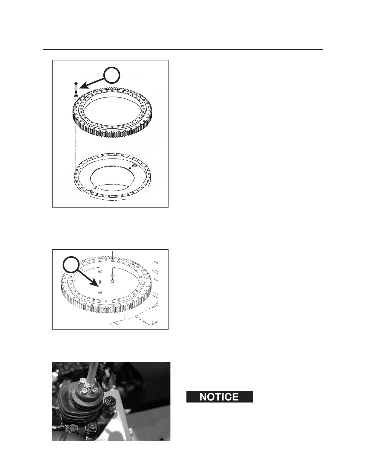
A
1121
Scheduled & Periodic Maintenance
31. CHECK OUTER SWING BEARING FAS
TENER TORQUE
Check that the outer swing bearing fasteners (A) are
torqued at 360 ft-lbs (490 N•m) torque.
If fasteners are damaged, replace with new.
If a fastener will not tighten to the specied torque, replace with a new fastener. Also remove and replace the
2 fasteners on either side of the damaged (replaced)
fastener.
B
32. CHECK INNER SWING BEARING FAS
TENER TORQUE
Check that all inner swing bearing fasteners (B) are
tightened to 730 ft-lbs (993 N•m) torque.
If fasteners are damaged, replace with new.
If a fastener will not tighten to the specied torque,
replace with a new fastener. Also, remove and replace
the 2 fasteners on either side of the damaged (replaced) fastener.
33. LUBRICATE JOYSTICK
Remove protective boot to gain access to joystick
components.
If signs of corrosion,
moisture and/or oil leakage are present, contact an
authorized dealer.
Lubricate joystick moving parts.
Page 86
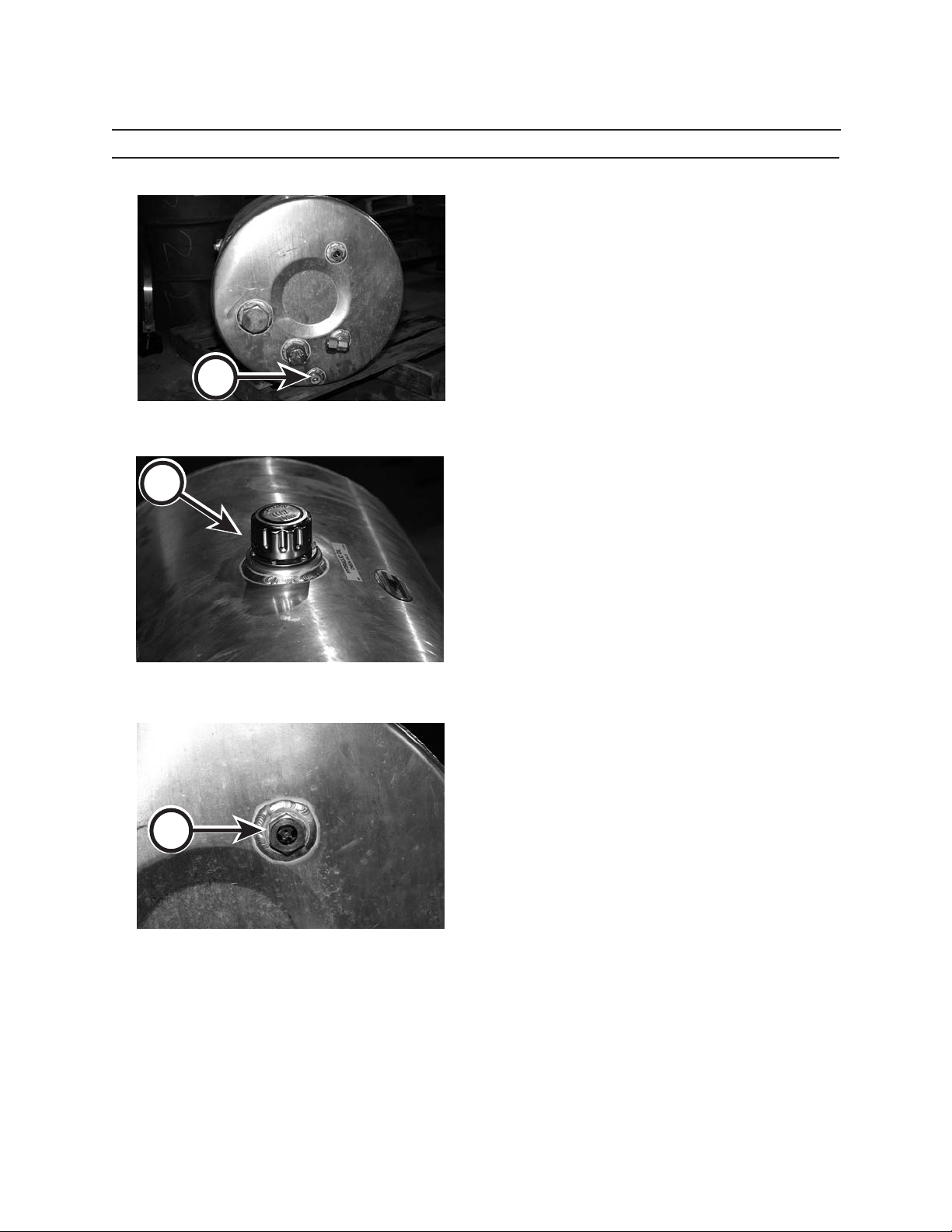
1122
Sheduled & Periodic Maintenance
EVERY SIX MONTHS OR 1200 HOURS
34. CHANGE HYDRAULIC RESERVOIR OIL
1. Position the machine on level ground. The boom
should be in transport position and stabilizers
should be raised.
2. Shut engine down and remove key.
3. Move joysticks in all directions to relieve hydraulic
pressure.
B
C
A
4. Open reservoir ller/breather to release reservoir
pressure.
5. Gain access to the hydraulic drain plug (A).
6. Clean around drain plug.
7. Remove the drain plug and drain hydraulic oil into
properly-sized catch pan. Dispose of oil properly.
8. Reinstall drain plug.
FILLING HYDRAULIC RESERVOIR
1. Clean area around ller cap (B).
2. Remove ller cap.
3. Insert clean hose into oil supply container with
nozzle end in hydraulic oil reservoir.
4. Fill reservoir until oil reaches the top of hydraulic
reservoir sight gauge (C). Hydraulic oil capacity is
42 gallons (159 L).
Page 87
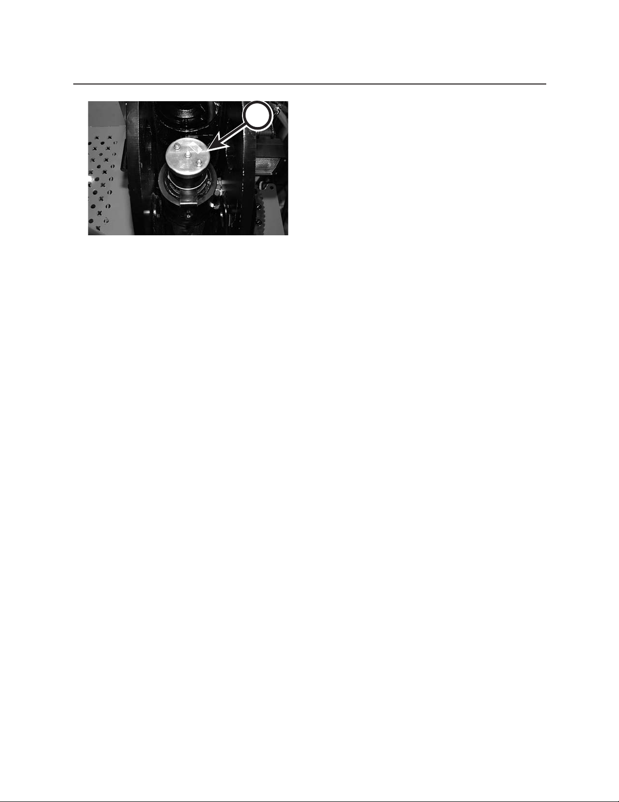
1123
Scheduled & Periodic Maintenance
A
35. CHECK/CLEAN COLLECTOR RING
1. Shut engine down and remove key.
2. Remove collector ring cover (A).
3. Spray collector with quality contact cleaner.
4. Check wire conections and brushes. Replace, if
necessary.
5. Replace collector cover.
Page 88

1124
Sheduled & Periodic Maintenance
Page 89

121
Storage
PREPARING MACHINE FOR STORAGE
If possible, store machine under cover and out of weather, in well-ventilated area. Store
attachment on rm, level ground. Block tires to prevent accidental machine movement. See engine operator’s manual
for proper engine storage.
. If machine will be stored for an extended period, or stored in a corrosive environment
(such as salt air or industrial pollution), using a sponge, apply Chrome Kote Corrosion Preventive to portions exposed
to air. Also apply Chrome Kote Corrosion Preventive to radiator, oil cooler ns, and all wiring connections. Reapply
Chrome Kote Corrosion Preventive every 3 months while machine remains in storage.
1. Operate machine long enough to warm uids. Check for leaks after machine warms up.
2. Drain hydraulic oil, ush oil reservoir.
3. Change hydraulic lters, rell hydraulic tank.
4. Repair worn or damaged parts. Install new parts, if necessary.
5. Grease machine thoroughly. Lubricate all grease points. Grease threads on bolts used for adjustments.
Coat exposed cylinder rods with Chrome Kote Corrosion Preventive to
retard rusting.
6. Restart and operate machine long enough to warm uids. Check for leaks after machine
warms up.
7. Thoroughly wash machine and attachments.
8. Repaint machine where necessary.
9. Store loader in transport position (refer to Transporting Section in this manual).
10. Wipe up lube spills.
11. Dispose of rags and trash. Dispose of used uids properly.
12. Block tires to prevent accidental truck movement.
13. Seal openings with moisture-resistant tape to prevent animals and insects from building nests inside ma-
chine.
14. See engine operator’s manual for proper engine storage.
15. See truck operator’s manual for proper truck storage.
Page 90

122
Storage
TAKING THE MACHINE OUT OF STORAGE
1. Clean machine and attachments thoroughly.
2. Remove sealing tape from engine openings.
3. Check all oil levels. If low, check for leaks; add oil as required.
4. See engine operator’s manual for information on restoring engine to service.
5. See truck operator’s manual for information on restoring truck to service.
9. Cycle all hydraulic functions several times.
10. Check condition of all hoses and connections.
11. Review this operator’s manual.
Chrome Kote Corrosion Preventive is compatible with hydraulic oil and seal materials. It does not have to be
removed when taking machine out of storage. When using a dierent brand of corrosion preventive, be sure to
check manufacturer’s recommendations on whether it should be removed prior to operation.
Page 91

131
Troubleshooting
HYDRAULIC SYSTEM
PROBLEM POSSIBLE CAUSE SOLUTION
Hydraulic system does not work. Low hydraulic oil level. Add hydraulic uid.
PTO not engaged. Engage PTO.
Plugged suction line. See an authorized dealer.
Defective pump drive. See an authorized dealer.
Hydraulic system is noisy, vibrating. Air in system. Check uid level and see an authorized
dealer if problem persists.
Cylinder “settle.” Leaking piston seals. See an authorized dealer.
Controls slow and/or lack power. Lack of hydraulic oil. Check/add hydraulic oil (see Lubricants
section for recommended
hydraulic oils).
Aeration in suction lines. Tighten hose ttings.
Improper adjustment of relief valves. See an authorized dealer.
Cylinder functions poorly and/or lacks Cold oil. Warm up system.
power. Engine at idle speed. I
Wrong hydraulic oil. Replace hydraulic oil (see Lubricants
section for recommended
hydraulic oils).
Damage to cylinder seals. Replace seals.
Aeration in cylinders. Bleed air from line.
Malfunctioning control valve. Repair or replace control valve.
Swing is slow or impossible to move. Transit lock engaged. Remove transit lock pin.
Obstruction under swing pedal. Remove obstruction.
Control valve problem. Repair or replace control valve.
Swing motor problem. Repair or replace swing motor.
Damage to swing gears. Repair or replace swing gear.
Damage to swing bearing. Repair or replace swing bearing.
Hydraulic uid is foaming. Suction line air leak. Repair or replace suction line.
Low hydraulic oil leak. Add hydraulic oil.
Water in hydraulic uid. Replace hydraulic uid and lters.
Hydraulic uid temperature is too high. Wrong viscosity oil. Replace hydraulic oil.
Engine speed too high. See an authorized dealer.
Worn pump. See an authorized dealer.
Defective relief valve. See an authorized dealer.
Internal cylinder leakage or control valve. See an authorized dealer.
Control valve reliefs. See an authorized dealer.
Loader is being operated over approved relief Install new lters/see dealer.
pressure settings.
Plugged lters. Install new lters/see dealer.
ncrease engine speed ot recomended speed.
Page 92

132
Troubleshooting
CLEANLINESS OF HYDRAULIC COMPONENTS
Cleanliness in hydraulics is essential. Be sure to keep contaminants out of the machine’s hydraulic system. Maintain the loader properly to reduce the risk of contaminating hydraulic components.
Clearances in hydraulic components can be very small. Many hydraulic systems have clearances of less than 25
microns, or .001 inch. Abrasive particles can enter the space between moving parts and honed surfaces to wider
clearances. Increased clearance decreases the eciency of pumps, motors, and cylinders. This damage wastes
horsepower and generates potentially damaging system heat.
The following gure lists the sizes of dierent common particles in inches and microns to show how even very
small particles can contaminate hydraulic components.
NOTE: Contaminant particle size is measured in microns. One micron equals one millionth of a meter,
or .000039 inch.
INCHES MICRONS
130
.005
.004
.003
.002
.001
120
110
100
90
80
70
60
50
40
30
20
10
2
Table salt
200 Mesh screen
Human hair
Pollen
Fog
Visibility limit
White blood cells
Talcum
Bacteria
Red blood cells
Page 93
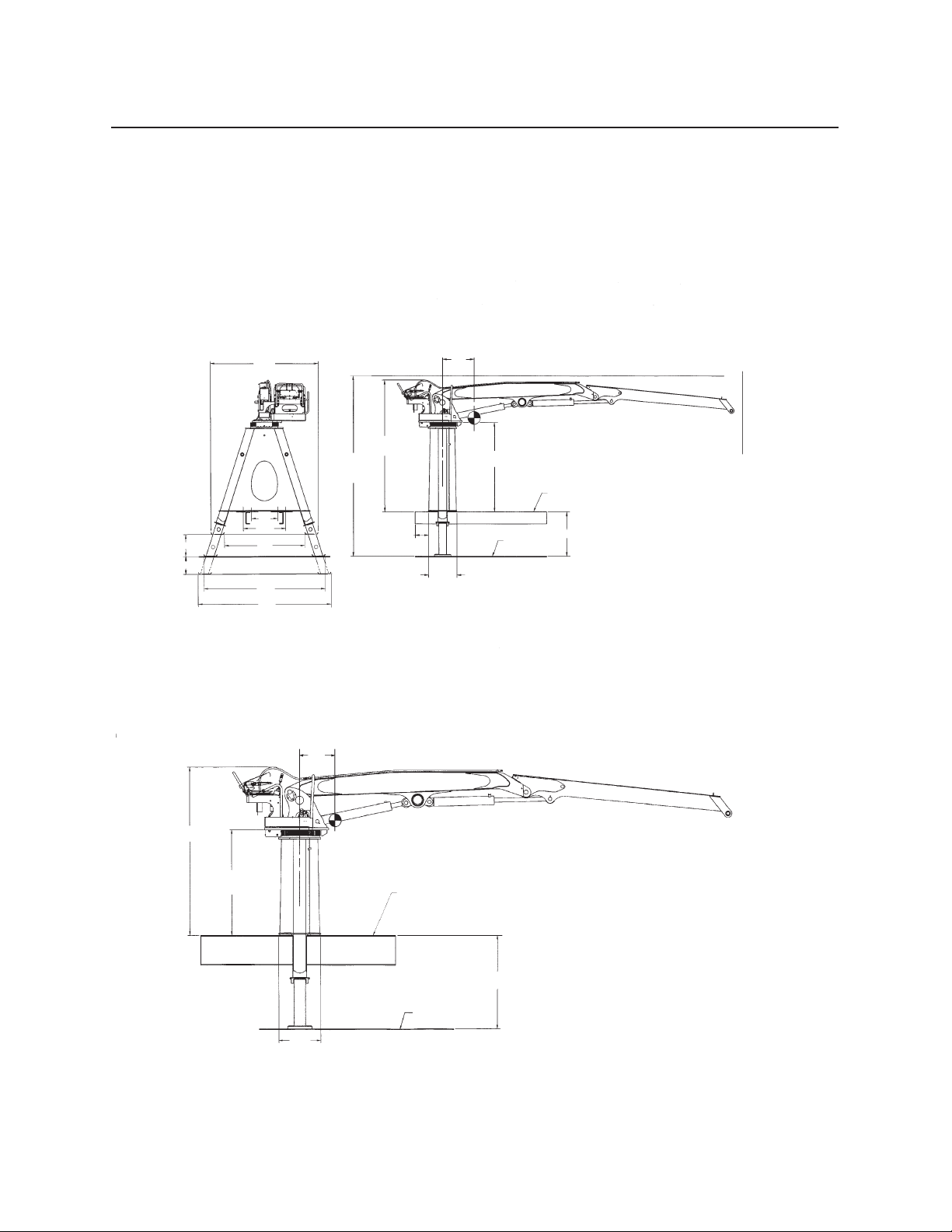
2124 DIMENSIONS
PRENTICE 2124 SELF-LOADER TRUCK MOUNT
99”
20”
16”
24”
39”
74”
111”
122”
20”
118”
162”
Road
Restriction
Center of Gravity
81” A-Frame Height
Truck Frame
40” Truck Height
Ground
Allow 6” to 12”
Between Cab
and Loader if
BC Mounted
26”
A-Frame
Width
Before mounting any loader: consult the truck body manufacturer
for installation precautions and recommendations. Failure to follow
manufacturers recommendations could result in damage to the truck.
Minimum Carrier is a single axle truck with frame section modules of 18 cu. in. and GVW rating of 27,000 lbs.
Recommended Carrier is a live tandem truck with frame section modules of 18 cu. in. and GVW rating of 32,000 lbs.
PRENTICE 2124 SELF-LOADER TRAILER MOUNT
20”
102”
Center of Gravity
Trailer Frame
64”
A-Frame
Height
56” Trailer Height
Ground
26”
A-Frame
Width
141
Specications
Page 94
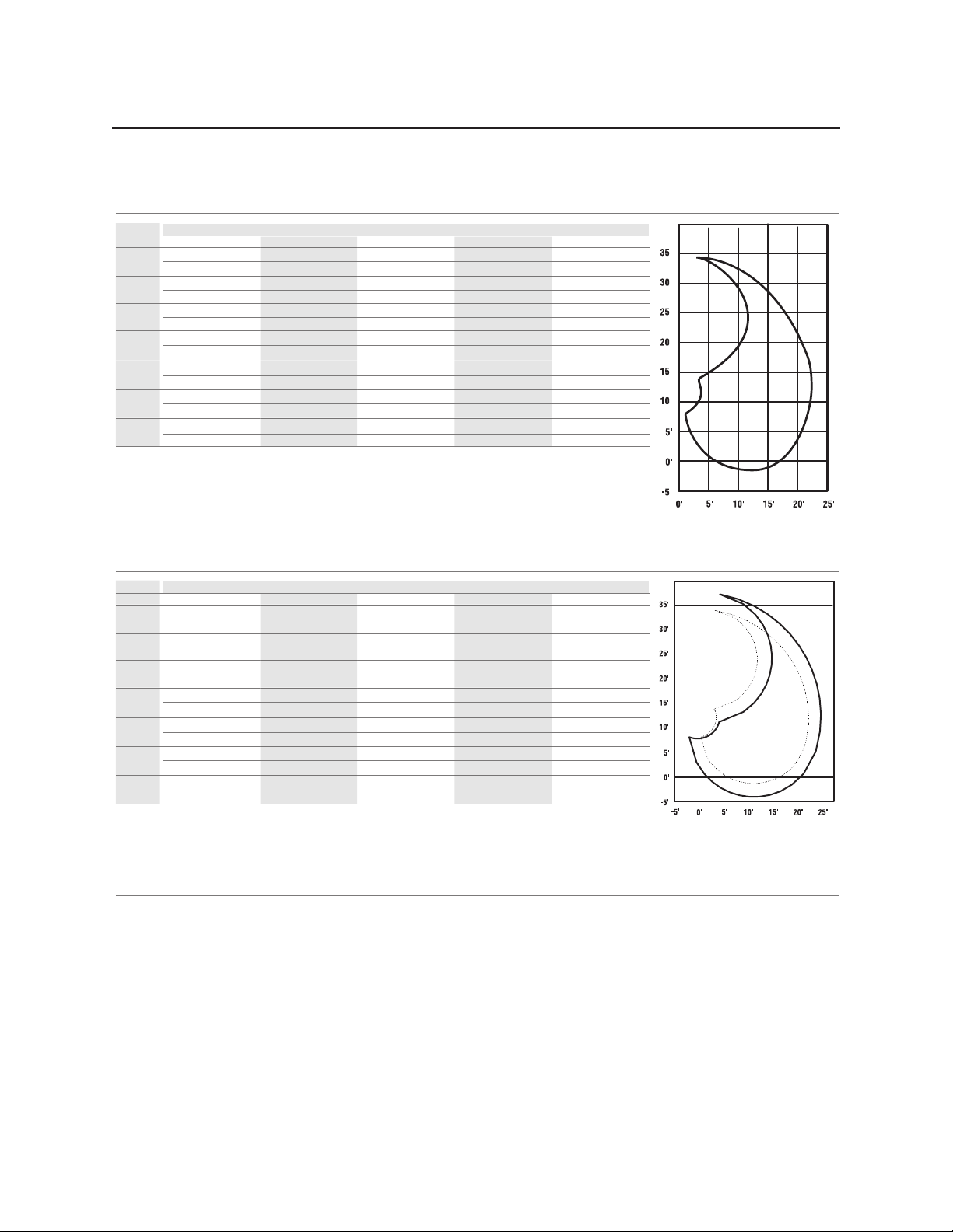
142
2124 LIFT CAPACITY
NOTES:
Capacities shown in “Black” are 100% of main cylinder hydraulic capability; capacities shown in “Red” are 87% of hydraulic
capacity.
Notice that some of the lifts in “Red” are higher than main only, since the stick has mechanical advantage and the limiting lift is the
main relief.
Lift Capacity Chart PRENTICE 2124 • Boom Type: Knuckleboom • Boom length: 22’ (6.7m)
9.1m (30’/)
7.6m (25’/)
6.1m (20’/)
4.6m (15’/)
3m (10’/)
1.5m (5’/)
0 0.0
Lift Capacity Chart PRENTICE 2124 • Boom Type: Knuckleboom • Boom length: 25’ (7.62m)
lbs.
3974
4898
kg.
1802
2222
lbs.
5528
6842
7626
9325
8900
9058
8608
6544
6172
kg.
2507
3103
3459
4230
4037
4109
3904
2968
2800
lbs.
4613
5302
5198
5358
6030
5755
6363
6056
5974
5664
4087
3838
kg.
2092
2405
2358
2430
2735
2610
2886
2747
2710
2569
1854
1741
lbs.
3324
4070
4545
4591
4538
3582
4349
3369
kg.
1508
1846
2062
2082
2058
1625
1972
1528
2962
2500
2298
2314
2242
2327
3329
lbs.
12762
14727
5077
5835
6522
7496
kg.
5789
6680
2303
2647
2958
3400
lbs.
7960
8074
9332
8864
8191
7736
kg.
3611
3662
4233
4021
3715
3509
lbs.
3975
4569
3915
4500
4099
4645
4802
5169
6059
5764
6243
5915
5390
5077
kg.
1803
2072
1776
2041
1859
2107
2178
2345
2748
2614
2831
2683
2445
2303
lbs.
3259
3745
3663
4211
4169
4352
4706
4456
4460
4207
3216
3001
kg.
1478
1699
1661
1910
1891
1974
2134
2021
2068
1908
1459
1361
1995
1693
1634
1769
1693
1642
2592
1.5m (5’/) 4.6m (15’/) Full Reach3m (10’/) 6.1m (20’/)
1.5m (5’/) 4.6m (15’/) Full Reach3m (10’/) 6.1m (20’/)
9.1m (30’/)
7.6m (25’/)
6.1m (20’/)
4.6m (15’/)
3m (10’/)
1.5m (5’/)
0 0.0
Specications
Page 95

2124 SPECIFICATIONS
HYDRAULIC SYSTEM
Type Split ow tandem circuit hydraulic system. System pressure 3200 psi. (2,249,822.7 kg)
Operation Fully independent simultaneous operation of main boom and swing. Flow diverted to operate stabilizers.
Control Valves Stack sections with mechanical joysticks. Valves contain port reliefs and anti-cavitation valves for loader protection and cont rol. Port relief
settings are 2,671,664.4 kg (3800 psi.)
Cylinders 114.3 cm (4.5”) Main and stick double acting with solid rods.
Diagnostic Nipples Located at control valves.
Oil Filter Two return spin on lters, 2 nominal/10 absolute micron lter. Twenty ve micron case drain lter.
Oil Reservoir 159 liters (Forty two [42] gallon) capacity. Filtered breather, sight gauge. Cylindrical design, aluminum fabrication.
Pump Mounting Direct mounted PTO driven, bi-rotational, delivering 151liters (40 GPM). (Optional Chassis mount conguration.)
Loader Pump Tandem gear type (21 + 19) operating at 1650 rpm (max) through PTO. Pump rated for 2,460,743.5 kg (3500 psi.)
Swivel Steel barrel with Durabar core. Five passages for pressure, return and stabilizers. Eight ring electric collector standard for optional light
packages.
Hoses & Hydraulic Tubes 2,812,278.3 kg (4000 psi) rated hose with wear resistant coating. Steel ORS tubing.
Fittings ORS ttings.
KNUCKLE BOOM
Boom Length 6.7 m (22’) horizontal reach. 10.3 m (34’) working height to boom tip. (Optional Tele-Boom): 10.3 m (25’) horizont
al reach. 11. 2 m (37’)
working height to boom tip.
Boom Structure Boom is high tensile steel fabrication. Main boom equivalent to 25.4 cm (10”) x 15.2 cm (6”) Spar tube. Stick boom equivalent t o
20.3 cm (8”) x 15.2 cm (6”) spar tube.
Construction Welded high tensile steel “Knuckle type” boom with heat treated high alloy steel pins and aluminum-bronze pivot bushings; self- aligning
bushings at both ends of main and stick boom cylinders. Boom & cylinder pin bushings are greased through pins. Castings at bas e end,
stick end and midpoint of mainboom assembly
STABILIZERS
Type Telescopic A-frame stabilizers with individual platform control s for uneven terrain.
Structural Stabilizer legs are 17.8 cm (7”) x 17.8 cm (7”) high tensile steel tubing.
Stab Pads Stabilizer pads measure 25.4 cm (10”) x 38.1 cm (15”).
Clearances Ground clearance for stabilizers in retracted position is 50.8 cm (20”). Below grade reach in extended position is 40.6 cm (16” ).
Stowed Stabilizers stowed position 251.4 cm (99”) wide. Width at grade level 284.4 cm (112”) on 101.6 cm (40”) truck. Width fully ext ended
284.4 cm (122”).
STRUCTURAL
Pedestal “A-Frame” pedestal design is formed high strength steel plate.
Swing System Continuous rotation; ring and pinion gear set driven by an axial piston hydraulic motor through a planetary gearbox. Slewing ri ng is
65.1 cm (25.65”) diameter. Swing torque 71,014.91 kg (14,545 ft.lbs.).
Travel Swing system is secured by house lock during transit.
Travel Height 33.5 cm (13’ 2”) maximum stowed height above ground 101.6 cm (40”) truck frame height
Weight 2,585.4 kg (5,700 lbs) for the 6.7 m (22’) xed boom model and 2744.23 kg (6,050 lbs) for the 7.62 m (25’) tele boom model.
Mounting “A-frame” mounting base is 90.8 cm (35 3/4”) wide x 66 cm (26” ) long for mounting on standard truck chassis.
CYLINDERS
Main Boom (1) 11.4 cm (4.5”) Bore x 6.3 cm (2 1/2”) Rod
Stick Boom (1) 11.4 cm (4.5”) Bore x 6.3 cm (2 1/2”) Rod
Stabilizers (2) 7.6 cm (3”) Bore x 5 cm (2”) Rod
OPERATION OF LOADER
Operator’s Platform Platform right side mounted with fold over seat. Access to platform by single ladder.
Seat Fold down seat with armrests
Controls Two mechanical joysticks and proportional teleboom controls. Swing pedal with mechanical linkage. Individual controls for activ ation
of stabilizer.
WEIGHT 5700 lbs. with 22’ boom
Add 250 lbs for 25’ teleboom option
CAPACITY (Note: SAE Standard 87% Ratings)
Radius Elevation Lift Capacity
Radius
1.5 m (5’)
3 m (10’)
4.5 m (15’)
6 m (20’)
6.7 m (22’)
1.5 m (5’)
1.5 m (5’)
1.5 m (5’)
1.5 m (5’)
1.5 m (5’)
Lift Capacit
y
p y
2,290.6 kg
3,865.9 kg
2,525.1 kg
1,481.4 kg
945.2 kg
Note: Deduct grapple weight for payload
(5,050 lbs.)
(8,523 lbs.)
( 5,567 lbs.)
(3,266 lbs.)
(2,084 lbs.)
143
Specications
Page 96
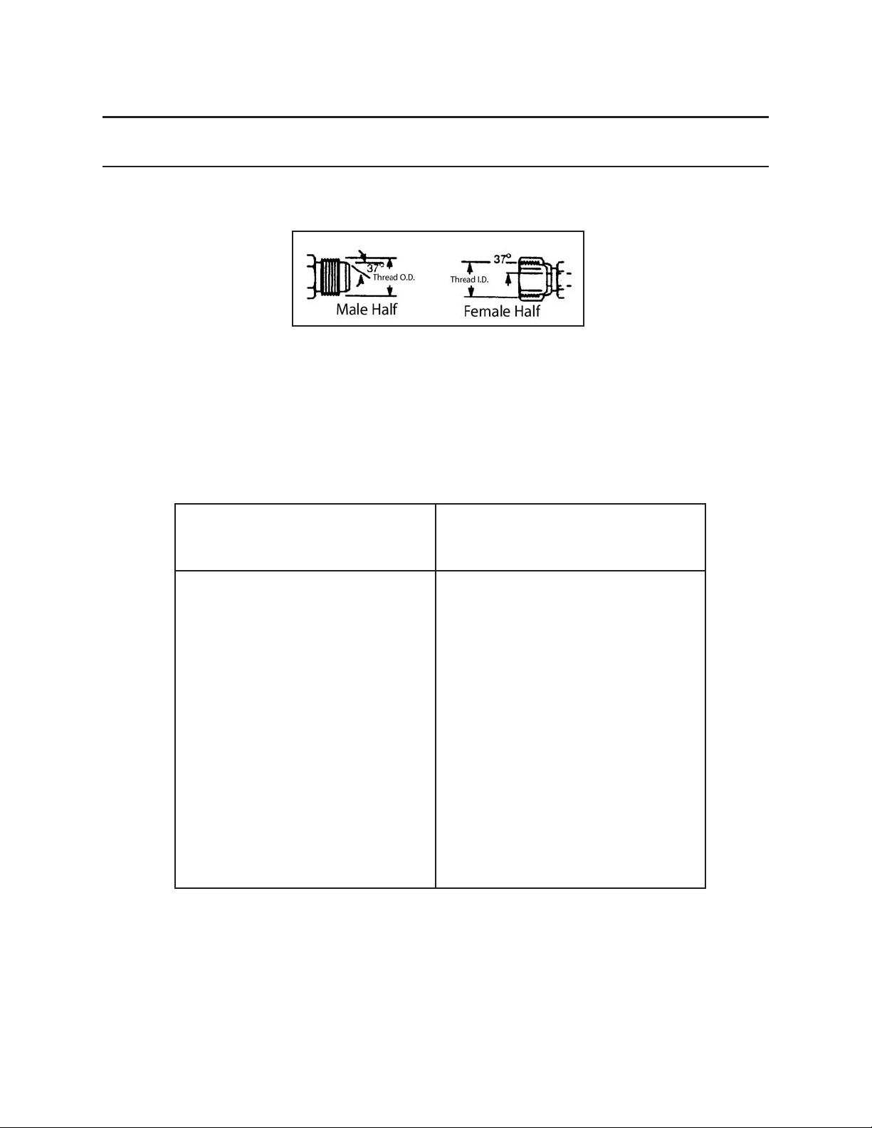
144
Specications
HYDRAULIC CONNECTION TORQUE SPECIFICATIONS
SAE 37° FLARE CONNECTION
HOW CONNECTION WORKS: HOW TO TIGHTEN CONNECTION:
This connection seals on two mating 37° seats. Use a torque wrench to rotate and tighten nut. Turn nut
to value shown in table below.
TORQUE
DASH SIZE THREAD SIZE INCHLBS NEWTONMETERS
-3 3/8 - 24 8-9 11-12
-4 7/16 - 20 11-12 15-16
-5 1/2 - 20 14-16 19-21
-6 9/16 - 18 18-20 25-27
-8 3/4 - 16 36-39 49-53
-10 7/8 - 14 57-63 77-84
-12 1 1/16 - 12 79-88 108-118
-14 1 3/16 - 12 83-92 113-2124
-16 1 5/16 - 12 108-113 147-153
-20 1 5/8 - 12 127-133 172-180
-24 1 7/8 - 12 158-167 215-225
-32 2 1/2 - 12 245-258 332-350
The above torque values are good for:
• machined adapters and hose ttings
• ared tubed (with sleeve and nut)
• universal radius ared tubes
Page 97
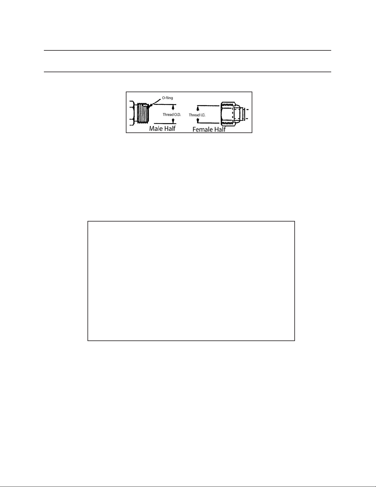
HYDRAULIC CONNECTON TORQUE SPECIFICATION
ORING FACE SEAL CONNECTION
G.158.02
HOW CONNECTION WORKS
This connection seals with an o-ring on the male against a at surface.
HOW TO TIGHTEN CONNECTION
Use a torque wrench to rotate and tighten nut. Turn nut to value shown in table below.
145
Specications
TORQUE
DASH SIZE THREAD SIZE INCHLBS NEWTONMETERS
-4 9/16 - 18 19 26
-6 11/16 - 16 31 42
-8 13/16 - 16 46 62
-10 1-14 71 96
-12 1 3/16 - 12 91 123
-16 1 7/16 - 12 130 176
-20 1 11/16 - 12 171 232
-24 2 -12 210 285
Make sure the o-ring does not fall out of the male end before connection is made.
Proper lubrication helps.
Page 98
146
Specications
TORQUE CHART FOR ENGLISH FASTENERS
This torque chart applies to lubricated threads for bolts, capscrews, and studs.
These specications do not apply to self-locking nuts or capscrews. To obtain proper torque, do not use lock
washers. Hardened at washers are recommended.
GRADE 8 FASTENERS
COARSE THREAD FINE THREAD
Nominal Size Torque (ft-lbs) Torque (N•m) Nominal Size Torque (ft-lbs) Torque (N•m)
1/4 - 20 8-9 11-12
5/16 - 18 17-19 23-26
3/8 - 16 33-36 45-49
7/16 - 14 52-57 71-77
1/2 - 13 76-84 103-114
9/16 - 12 105-115 142-156
5/8 - 11 162-178 220-241
3/4 - 10 266-294 361-399
7/8 - 9 437-483 593-655
1 - 8 646-714 876-968
1 1/8 - 7 912-1008 1237-1367
1 1/4 - 7 1292-1428 1752-1936
1 1/2 - 6 2242-2478 3040-3360
1 3/4 - 5 3048-3688 4133-5001
2 - 4 1/2 4610-5096 6251-6910
1/4 - 28 9-10 12-14
5/16 - 24 19-21 26-28
3/8 - 24 35-37 46-50
7/16 - 20 53-58 72-79
1/2 - 20 86-94 117-128
9/16 - 18 2124-136 168-184
5/8 - 18 171-189 232-256
3/4 - 16 304-336 412-456
7/8 - 14 475-525 644-712
1 - 12 703-777 953-1054
1 1/8 - 12 979-1081 1328-1466
1 1/4 - 12 1425-1575 1932-2136
1 1/2 - 12 2527-2793 3427-3787
1 3/4 - 12 4004-4424 5429-5999
2-12 6116-6760 8293-9167
Use these torque values unless otherwise specied. Exceptions are noted where applicable. SAE Grade 8 fasteners (A.S.T.M. A354, Grade BD) are made from quenched and tempered medium carbon steel. Grade 8 fasteners
have 6 equally spaced radial lines embossed on the head of the fastener (see illustration below).
Page 99
Specications
M4 x .70 Pitch 8.8 3.1 2.2 2.30 1.65
M5 x .80 Pitch 8.8 6.1 5.5 4.58 4.13
M6 x 1.00 Pitch 8.8 10.4 9.5 7.80 7.13
M7 x 1.00 Pitch 8.8 17.0 15.5 12.75 11.63
M8 x 1.25 Pitch 8.8 25.0 23.0 18.75 17.25
M8 x 1.00 Pitch 8.8 27.0 24.5 20.25 18.38
M10 x 1.50 Pitch 8.8 51.0 46.0 38.25 34.50
M10 x 1.00 Pitch 8.8 57.0 52.0 42.75 39.00
M10 x 1.25 Pitch 8.8 54.0 49.0 40.50 36.75
M12 x 1.75 Pitch 8.8 87.0 79.0 65.25 59.25
M12 x 1.25 Pitch 8.8 96.0 87.0 72.00 65.25
M12 x 1.50 Pitch 8.8 92.0 83.0 69.00 62.25
M14 x 2.00 Pitch 8.8 140.0 125.0 105.00 93.75
M14 x 1.50 Pitch 8.8 150.0 135.0 112.50 101.25
M16 x 2.00 Pitch 8.8 215.0 195.0 161.25 146.25
M18 x 2.50 Pitch 8.8 300.0 280.0 225.00 210.00
M20 x 2.50 Pitch 8.8 430.0 390.0 322.50 292.50
M22 x 2.50 Pitch 8.8 580.0 530.0 435.00 397.50
M24 x 3.00 Pitch 8.8 740.0 670.0 555.00 502.50
M6 x 1.00 Pitch 10.9 15.5 14.0 11.63 10.50
M8 x 1.25 Pitch 10.9 37.0 34.0 27.75 25.50
M10 x 1.50 Pitch 10.9 75.0 68.0 56.25 51.00
M12 x 1.75 Pitch 10.9 160.0 117.0 97.50 87.75
M14 x 2.00 Pitch 10.9 205.0 185.0 153.75 138.75
M16 x 2.00 Pitch 10.9 310.0 280.0 232.50 210.00
Size Class Zinc Plated Unplated Zinc Plated Unplated
Newton Meters Foot Pounds
Torque-Chart-2
GRADE 8.8 & 10.9 FASTENERS
TORQUE CHART FOR METRIC FASTENERS
This torque chart applies to lubricated threads for bolts, capscrews, and studs.
These specications do not apply to self-locking nuts or capscrews. To obtain proper torque, do not use lock
washers. Hardened at washers are recommended.
147
Use these torque values unless otherwise specied. Exceptions are noted where applicable. SAE Grade 8 fasteners (A.S.T.M. A354, Grade BD) are made from quenched and tempered medium carbon steel. Grade 8 fasteners
have 6 equally spaced radial lines embossed on the head of the fastener (see illustration below).
Page 100
148
SNOITACIFICEPSEUQROTREDNILYC
yrD,swercSpaCdaeHxeHdetalp–cniZ8edarG
eziShsaD euqroT
.sbl.tf m•N
7
/
61
CNU41– 48–67 411–301
1
/
2
CNU31– 511–501 651–241
sdaerhTdetacirbuL,hsiniFliOdna.sohP,stuNkcoLcitsalE8edarG
eziShsaD euqroT
.sbl.tf m•N
FNU41–1 045 237
11/
4
FNU21– 057 7101
13/
8
FNU21– 0001 6531
11/
2
FNU21– 0021 7261
13/
4
FNU21– 0051 4302
21/
4
FNU21– 0052 0933
Specications
CYLINDER TORQUE SPECIFICATIONS
 Loading...