

Page 1

GROUP 11 ENGINE
SPECIFICATIONS ............................................................................. 11-2
STRUCTURE AND OPERATION
1. Engine Proper .................................................................................... 11-3
2. Rocker and Bracket Assembly, Camshaft, Rocker Case and
Cylinder Head Gasket ........................................................................
3. Valve Mechanism ............................................................................... 11-4
4. Connecting Rod ................................................................................. 11-5
5. Piston .................................................................................................. 11-5
6. Timing Gears ...................................................................................... 11-6
7. Flywheel .............................................................................................. 11-7
TROUBLESHOOTING ...................................................................... 11-8
GENERAL INSPECTION AND ADJUSTMENT
1. Measuring Compression Pressure ................................................ 11-10
2. Inspection and Adjustment of Valve Clearances .......................... 11-12
11-4
11
ROCKER COVER, ROCKER BRACKET AND CAMSHAFT ........... 11-16
CYLINDER HEAD AND VALVE MECHANISM ................................ 11-24
PISTON AND CONNECTING ROD, CYLINDER LINER .................. 11-40
FLYWHEEL ...................................................................................... 11-54
TIMING GEARS ............................................................................... 11-62
CRANKSHAFT AND CRANKCASE ................................................. 11-68
11-1
Page 2
SPECIFICATIONS
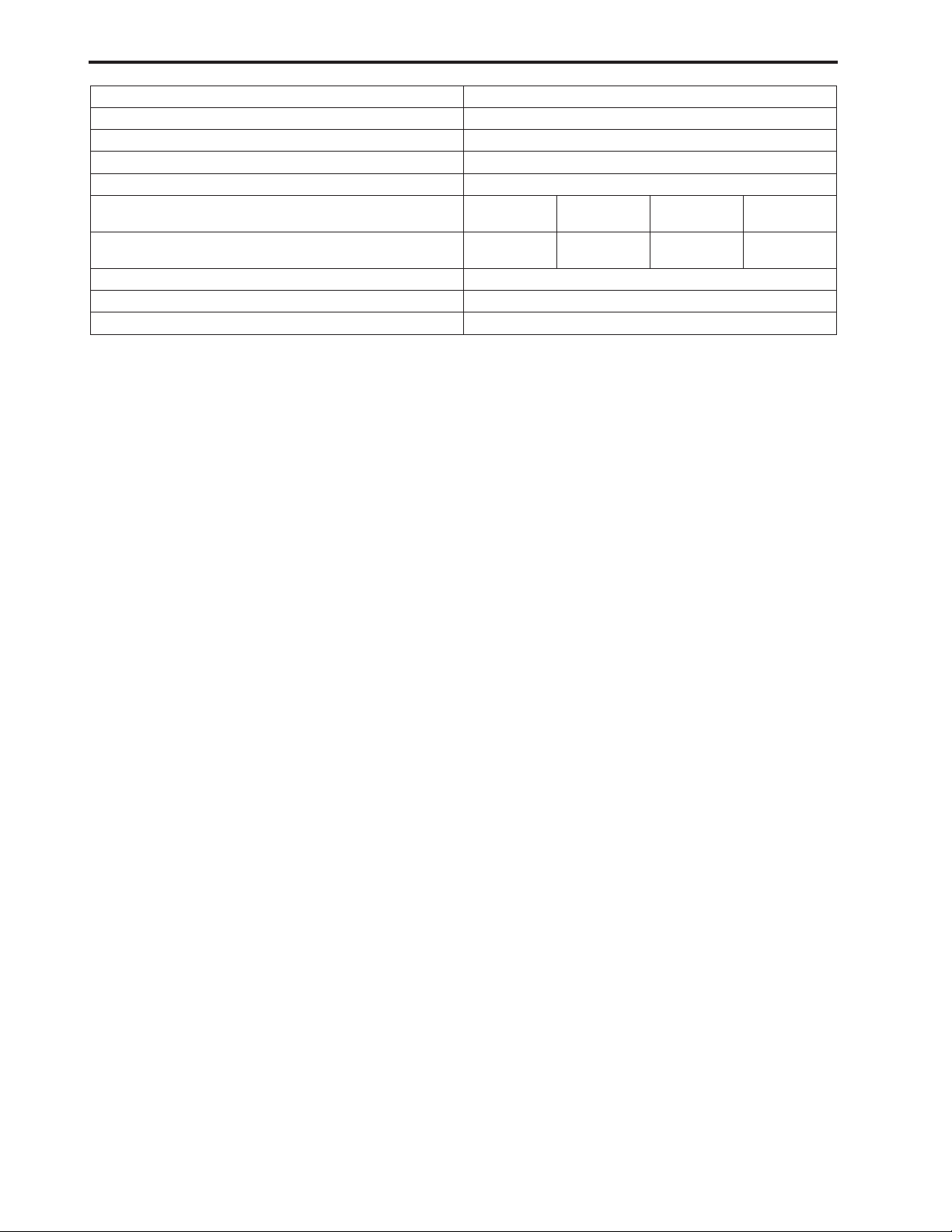
Item Specifications
Engine mode 6M60-TL
Type 6-cylinder, in-line, water-cooled, 4-cycle diesel engine
Combustion chamber Direct injection type
Valve mechanism Overhead camshaft (OHC) system
Maximum output kW {PS} /rpm
Maximum torque N·m {kgf·m} /rpm
Bore × stroke mm φ118 × 115
3
Total displacement cm
Compression ratio 17.5
{L} 7545 {7.545}
110 {150} /
2100
610 {62} /
1600
129 {175} /
2100
700 {71} /
1600
145 {195} /
2600
740 {75} /
1400
200 {270} /
2600
785 {80} /
1400
11-2
Page 3
STRUCTURE AND OPERATION
1. Engine Proper
11
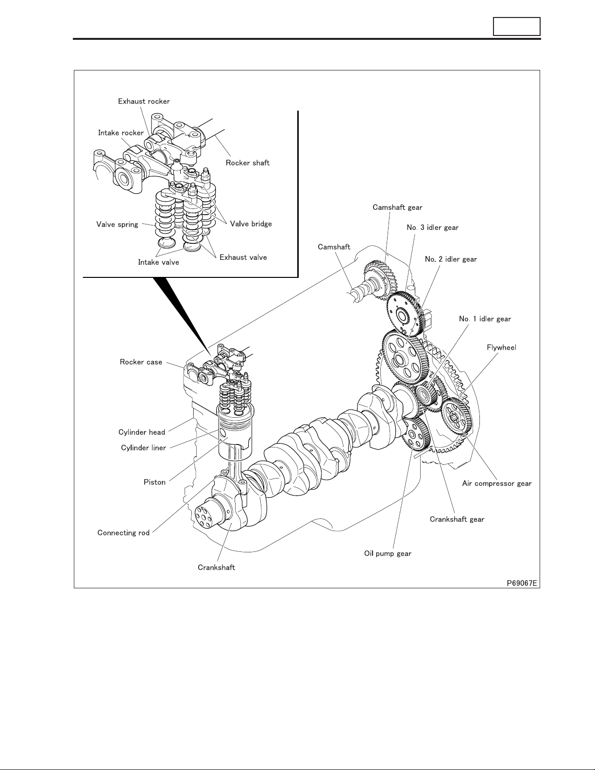
• The 6M60-TL engine employs an overhead camshaft (OHC) system, with the valve mechanism and the timing
gears arranged as shown above.
11-3
Page 4
STRUCTURE AND OPERATION
2. Rocker and Bracket Assembly, Camshaft, Rocker Case and
Cylinder Head Gasket
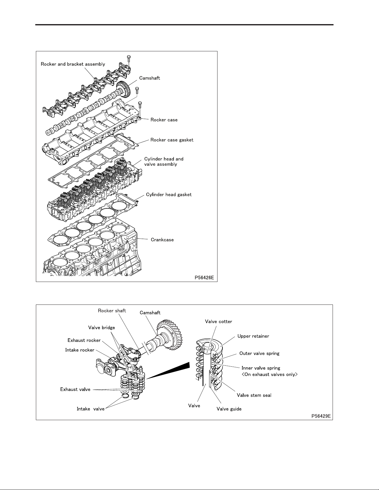
• The camshaft is directly supported at
its journals by the rocker case, and is
held in place from above by the rocker
and bracket assembly.
• The camshaft journals are directly
supported by the rocker case and the
rocker and bracket assembly, without
using any camshaft bearings. The
rocker case and brackets have been
machined together, meaning that they
all need to be replaced with a new set
when one of them becomes defective.
3. Valve Mechanism
• Each valve has a valve stem seal, which regulates the flow of lubricating oil to the contact surface between the
valve and the valve guide.
• The valve springs have a variable pitch to prevent abnormal vibration at high engine speed. The exhaust valves
use a double spring, with the inner and outer springs coiled in different directions to prevent them from jamming
each other.
11-4
Page 5
4. Connecting Rod
5. Piston
11
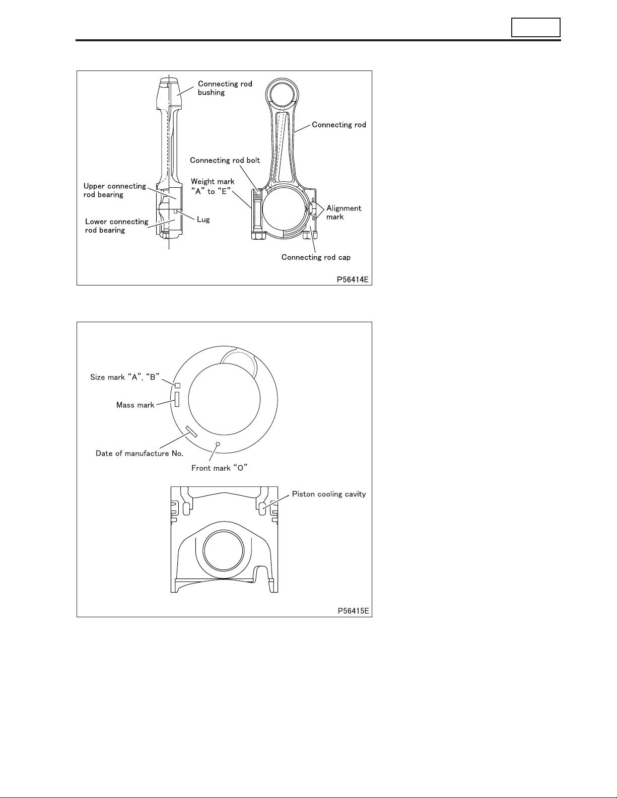
• The piston, the cylinder liner and the
crankcase bore all must have the
same size marks to ensure a good fit
between them.
• The pistons are made of special aluminum alloy, and are provided with a
recess on each end of the piston pin
boss to reduce weight.
11-5
Page 6
STRUCTURE AND OPERATION
6. Timing Gears
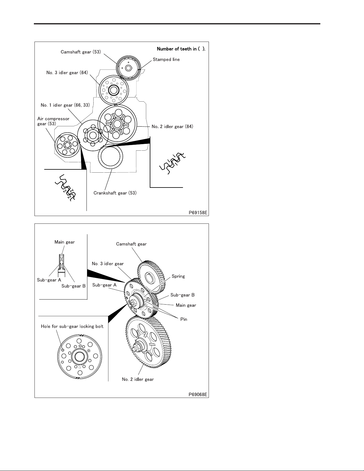
• The timing gears are provided with
timing marks to help ensure correct
assembly.
• Timing marks are provided on the following gears.
• Camshaft gear: stamped line
• Crankshaft gear: “1”
• Air compressor gear: “2”
• No. 1 idler gear: “1”, “2”
6.1 No. 3 idler gear
• The No. 3 idler gear consists of the
sub-gear A, the sub-gear B and the
main gear.
• A spring is installed between the subgear A and the main gear, as well as
between the sub-gear B and the main
gear. The springs are locked in place
with pins.
• The sub-gears are installed as follows.
The sub-gear A has been turned in
such a way as to compress the spring
before meshing with the camshaft
gear. Likewise, the sub-gear B has
been turned to compress the spring
before meshing with the No. 2 idler
gear.
11-6
Page 7
11
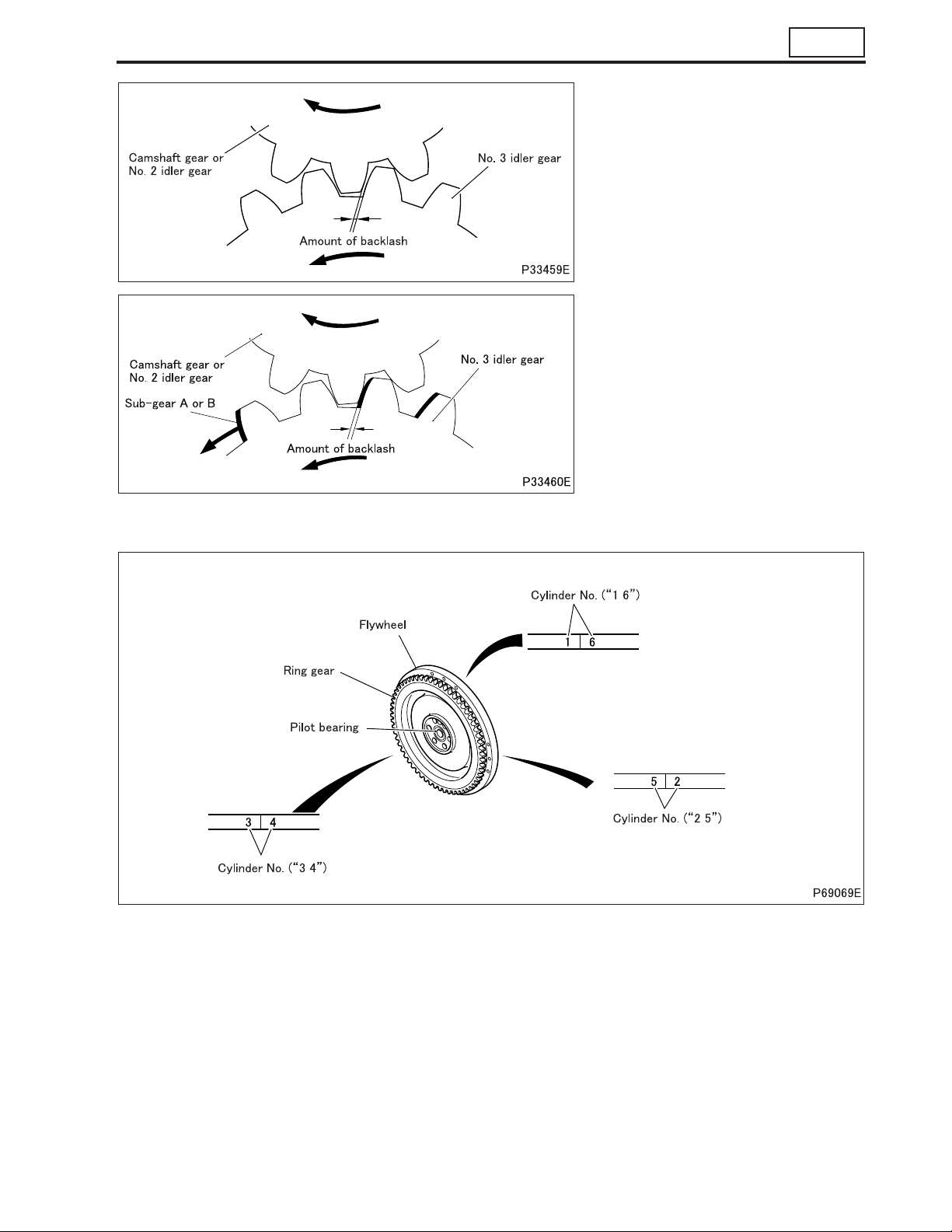
(1) Non-backlash mechanism
• Engine hunting during idling causes
fluctuation in the speed of camshaft
and No. 2 idler gears.
• Without the non-backlash mechanism,
the backlash changes between zero
and the maximum, generating gear
rattle noise.
• With the non-backlash mechanism
equipped on the engine, the sub-gears
A and B maintain the backlash to zero
even when the engine hunts, eliminating gear rattle during idling.
7. Flywheel
11-7
Page 8
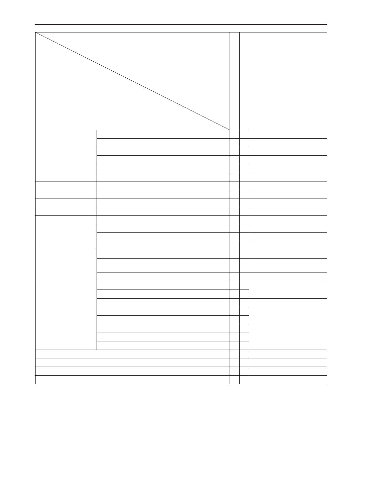
TROUBLESHOOTING
Symptoms
Reference Gr
Possible causes
Incorrect valve clearance O O
Defective cylinder head gasket O O
Cylinder head and valve
mechanism
Timing gears
Camshaft
Pistons and connecting
rods
Crankshaft
Fuel system
Cooling system
Intake and exhaust
system
Incorrect oil viscosity O Gr12
Improper fuel O
Incorrectly fitted piping and hoses O
Defective/incorrectly fitted alternator and other auxiliaries O
Worn valve and valve seat; carbon deposits O O
Weakened valve spring O O
Defective rocker shaft and bracket O
Poor lubrication of rocker shaft bracket O
Incorrect backlash in timing gears O
Poor lubrication of timing gears and idler shaft O
Excessive end play in camshaft O
Worn camshaft O
Worn/damaged piston ring groove(s) O O
Worn/damaged piston ring(s) O O
Worn piston pin and connecting rod small end O
Excessive end play in crankshaft O
Incorrectly fitted crankshaft pulley O
Worn/damaged crankshaft pins and connecting rod bearings
Worn/damaged crankshaft journals and main bearings O
Supply pump faulty O O
Defective injector O O
Air trapped in fuel system O Gr13A
Malfunctioning cooling system components O
Loose/damaged V-belts O
Clogged air cleaner O O
Malfunctioning turbochargers O O
Low power output
Abnormal engine noise
O
Gr13E
Gr14
Gr15Clogged muffler O O
11-8
Page 9

M E M O
11
11-9
Page 10
GENERAL INSPECTION AND ADJUSTMENT
1. Measuring Compression Pressure
Service standards
Location Maintenance item Standard value Limit Remedy
2,940 kPa
{30 kgf/cm
–
2
}
– Compression pressure
Each cylinder (at 200 rpm)
Cylinder-to-cylinder pressure difference
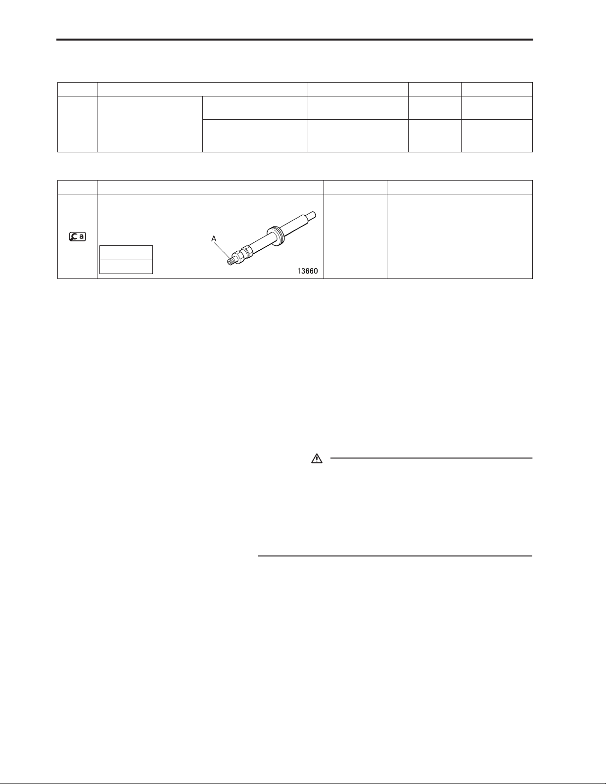
Special tools (Unit: mm)
Mark Tool name and shape Part No. Application
1,960 kPa
{20 kgf/cm2}
390 kPa
{4 kgf/cm
2
or less
Inspect
}
Inspect
Compression gauge
adapter
A
M16 × 18
MH063384 Measuring compression pressure
• A drop in compression pressure can be used as a guide to determine when the engine should be overhauled.
• Measure the compression pressure at regular intervals. Keeping track of its transitions can provide a useful tool
for troubleshooting. On new vehicles and vehicles with newly replaced parts, the compression pressure will be
somewhat higher depending on the break-in condition of piston rings, valve seats, etc., but this will return to normal as the parts wear down.
• Before inspection, confirm that the engine oil, starter, and battery are in normal condition, and satisfy the following
conditions.
• Warm up the engine until the coolant temperature reaches approximately 75 to 85°C.
• Turn off the lights and auxiliaries.
• Place the lever in neutral.
• Remove the fuse for fuel cut to prevent fuel from being injected
while the engine is cranked using the starter.
CAUTION
• When cranking the engine, never shut off the power supplied to the engine electronic control unit by disconnecting
the engine electronic control unit connector or other similar
methods. If the engine is cranked with the power to the engine electronic control unit shut off, the supply pump will
not be controlled by the electronic control unit, causing the
supply pump to be malfunctioned.
11-10
Page 11
11
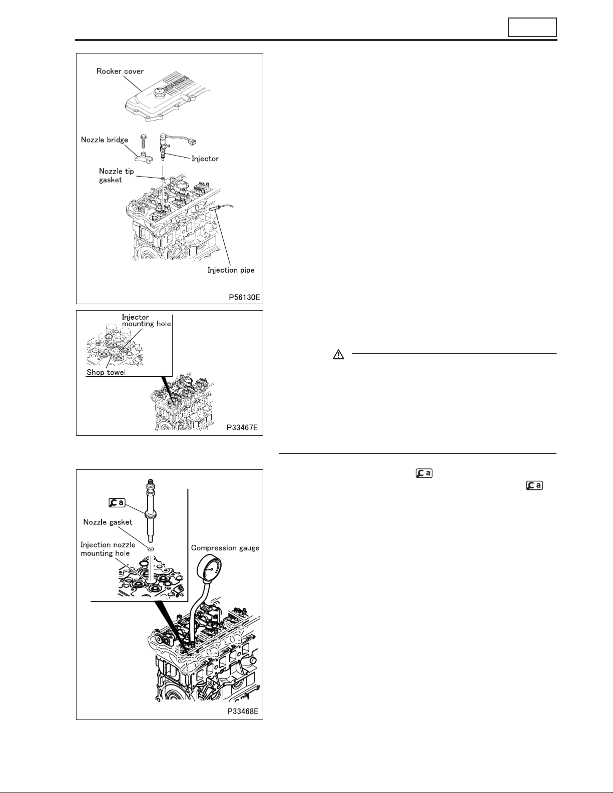
• Remove all the injectors. (See Gr13A.)
• Cover the injector mounting holes with shop towels or other sim-
ilar cloth. Crank the engine using the starter. Ensure that no foreign matter is attached on the shop towels.
CAUTION
• If cracks or any other damage are evident in the cylinders,
this means that the coolant, engine oil or fuel, or other substances, has entered the cylinders. If this is the case, it is
extremely dangerous to crank the engine as these substances will gush out at high temperature from the injector
mounting holes. Stay away from the engine when cranking
it.
• Attach the nozzle gasket and to one of the injection nozzle
mounting holes. Then, connect a compression gauge to .
• Crank the engine and measure the compression pressure.
• Measure the compression pressure for all the cylinders one after
another. Determine the compression pressure difference between the cylinders.
• If the compression pressure is below the limit or the cylinder-tocylinder pressure differences is not within the limit, pour a small
amount of engine oil into the corresponding injection nozzle
mounting hole and remeasure the compression pressure.
• If the compression pressure increases, the piston rings and
cylinder surfaces may be badly worn or otherwise damaged.
• If the compression pressure remains unchanged, there may
be seizure in the valves, the valves may be incorrectly seated
or the cylinder head gasket may be defective.
• Install the injectors. (See Gr13A.)
• Install the rocker cover and gasket. (See later pages.)
11-11
Page 12
GENERAL INSPECTION AND ADJUSTMENT
2. Inspection and Adjustment of Valve Clearances
Service standards (Unit: mm)
Location Maintenance item Standard value Limit Remedy
– Valve clearance (when cold) 0.6 – Adjust
Tightening torque (Unit: N·m {kgf·m})
Mark Parts to be tightened Tightening torque Remarks
– Lock nut (adjusting screw tightening) 59 {6.0} –
– Lock nut (rocker arm adjusting screw tightening) 34 {3.5} –
Special tools
Mark Tool name and shape Part No. Application
Socket wrench MH063003 Tightening the lock nut
• Valve clearances should be checked and adjusted as follows
while the engine is still cold.
[Inspection]
• Remove the rocker cover.
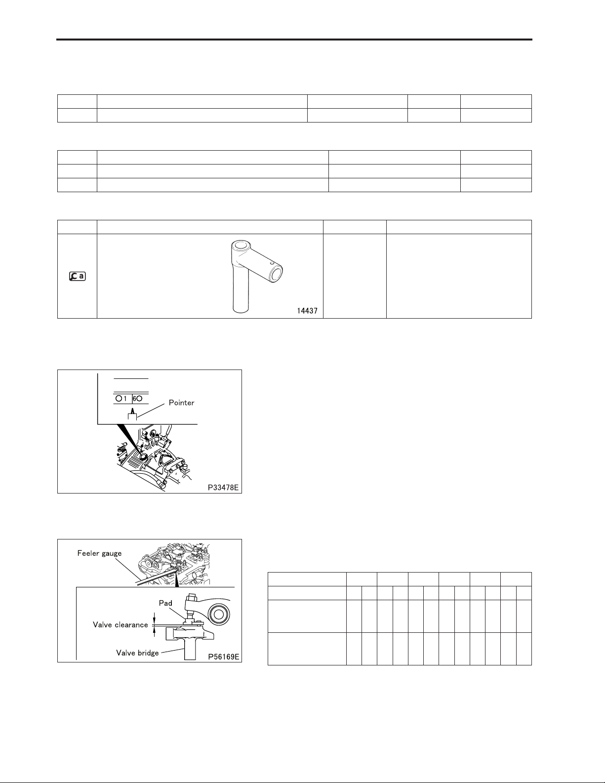
• Bring the No. 1 or No. 6 cylinder piston to the top dead center
(TDC) on the compression stroke according to the following procedure:
• Rotate the crankshaft until the pointer is aligned with the “1 6”
mark on the flywheel.
• This will place either the No. 1 or No. 6 cylinder piston at TDC
on the compression stroke. The cylinder in which the rocker
arms for both the intake and exhaust valves can be pushed
down by hand by the valve clearance amounts has its piston
at TDC. Rotate the engine by one full turn to switch the TDCs
of the No. 1 and No. 6 cylinder pistons.
• With the No. 1 or No. 6 cylinder piston at TDC, measure the
clearance of the valves (clearance between valve bridge and
pad) marked with a circle in the table below.
Cylinder No. 123456
Valve IN EX IN EX IN EX IN EX IN EX IN EX
No. 1 cylinder
piston at TDC on
compression stroke
No. 6 cylinder
piston at TDC on
compression stroke
OOO– – OO – – O– –
–––OO––OO–OO
11-12
Page 13
11
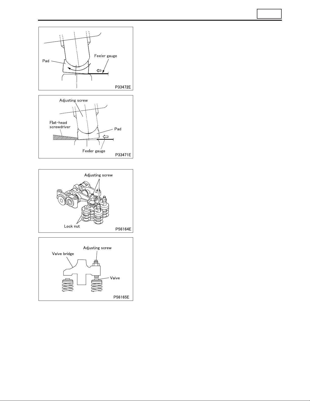
• Any attempt to insert a feeler gauge without first securing suffi-
cient space, as described above, between the pad and the valve
bridge will fail, as the pad will tilt as shown in the illustration, thus
blocking the entry of a feeler gauge.
• Before inserting a feeler gauge, push the adjusting screw pad on
the side opposite from where a feeler gauge is to be inserted, as
shown in the illustration, using a flat-head screwdriver or other
similar tool. This will create space necessary for the gauge to be
inserted.
• The measurement is correct when the feeler gauge feels slightly
resisted as it is inserted.
• The measurement is not yet correct if the feeler gauge can still
be inserted smoothly.
• If the measurement deviates from the standard value, adjust as
follows.
[Adjustment]
• Loosen the lock nuts and adjusting screws on the valve bridge
and rocker arm.
• While holding the valve bridge by hand, screw in the adjusting
screw until it lightly contacts the valve stem end.
• Then, further screw in the adjusting screw by 45°.
11-13
Page 14
GENERAL INSPECTION AND ADJUSTMENT
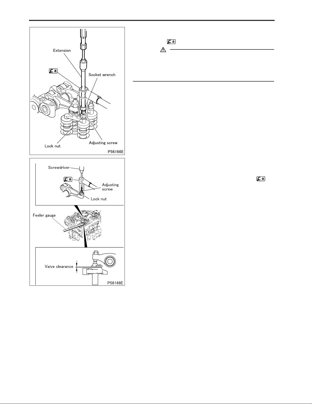
• While holding the adjusting screw in this position with a socket
wrench and extension, tighten the lock nut to the specified
torque using .
CAUTION
• After adjusting the adjusting screw, be sure to tighten the
lock nut to the specified torque. Insufficient torquing will
compromise the parallelism of the valve bridge, damaging
the valve mechanism.
• Screw in or out the adjusting screw on the rocker arm until the
correct feeler gauge can be inserted with a slight resistance.
• While holding the adjusting screw in this position with a screwdriver, tighten the lock nut to the specified torque using .
• Recheck the valve clearance using the correct feeler gauge.
11-14
[Installation]
• Install the rocker cover and gasket. (See later pages.)
Page 15

M E M O
11
11-15
Page 16
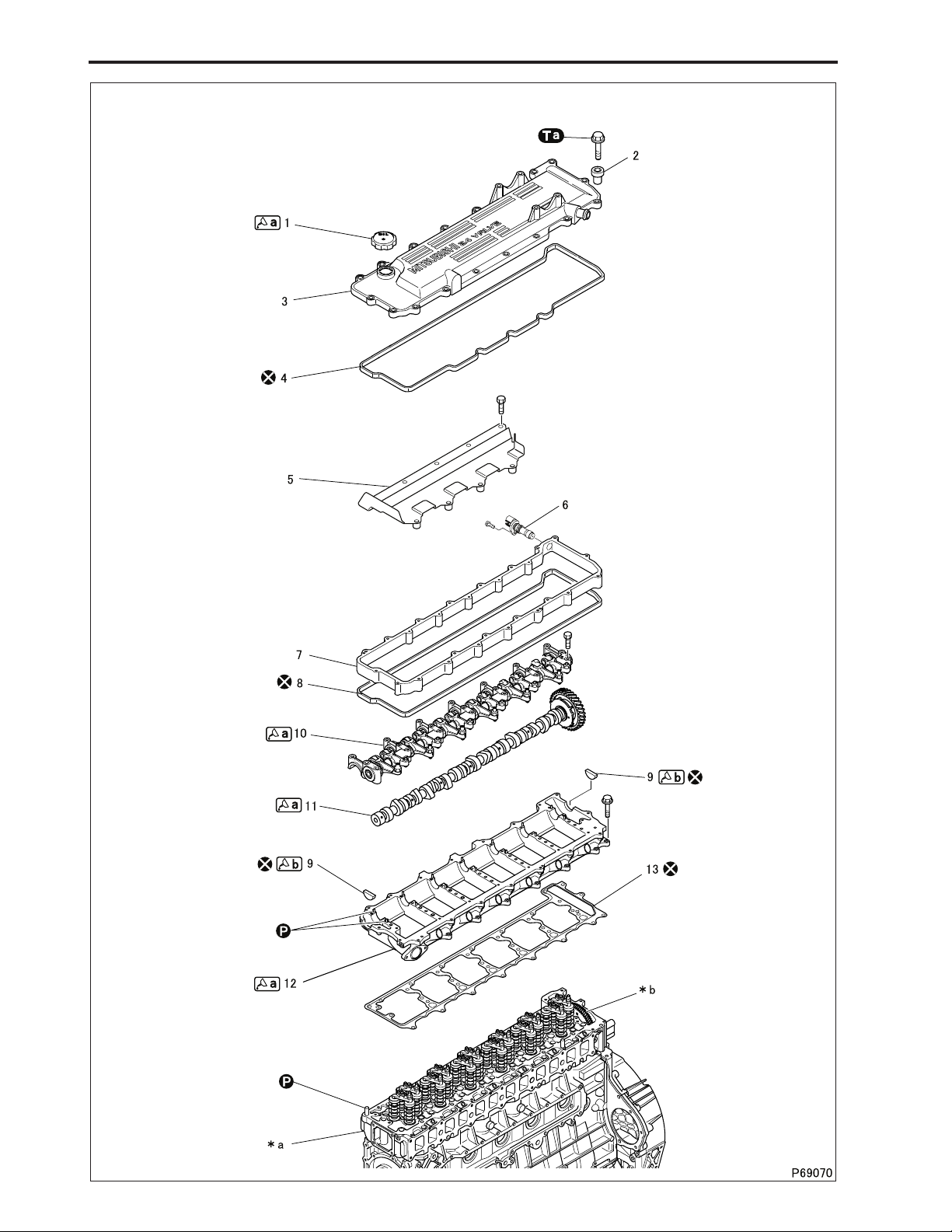
ROCKER COVER, ROCKER BRACKET AND CAMSHAFT
11-16
Page 17
11
Disassembly sequence
1 Oil filler cap
2 Rubber
3 Rocker cover
4 Rocker cover gasket
5 Baffle plate
6 Cylinder recognition sensor
7 Rocker case upper
CAUTION
• The rocker case and the brackets of the rocker and bracket assembly have been machined together,
which means that they all must be replaced together. Never swap the locations of the brackets, either.
Assembly sequence
Follow the disassembly sequence in reverse.
Service standards (Unit: mm)
Location Maintenance item Standard value Limit Remedy
– Camshaft end play 0.05 to 0.20 0.4 Inspect
b Backlash between camshaft gear and No. 3 idler gear 0.18 to 0.26 0.35 Replace
11,
*
8 Rocker case upper gasket
9 Packing
10 Rocker and bracket assembly
(See later pages.)
11 Camshaft
(See later pages.)
12 Rocker case
13 Rocker case gasket
a: Cylinder head
*
b: No. 3 idler gear
*
: Locating pin
: Non-reusable parts
Tightening torque (Unit: N·m {kgf·m})
Mark Parts to be tightened Tightening torque Remarks
Bolt (rocker cover mounting) 8.8 {0.9} –
Lubricant and/or sealant
Mark Points of application Specified lubricant and/or sealant Quantity
Rubber portion of oil filler cap
Camshaft journal supports on rocker and bracket assembly
Camshaft journals and cams
Camshaft journal supports on rocker case
Periphery and top surface of packing ThreeBond 1217H As required
Work before removal
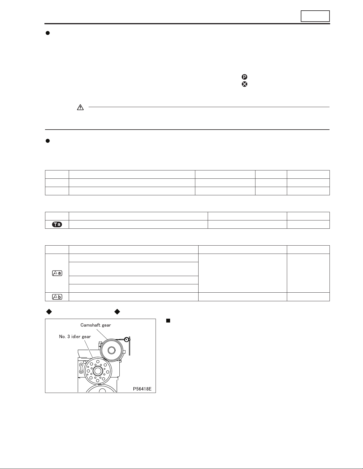
Inspection: Backlash between camshaft gear and No. 3 idler
gear
• Measure the backlash at least at three different locations. If the
measurement exceeds the limit, replace the defective part(s).
Engine oil As required
11-17
Page 18
ROCKER COVER, ROCKER BRACKET AND CAMSHAFT
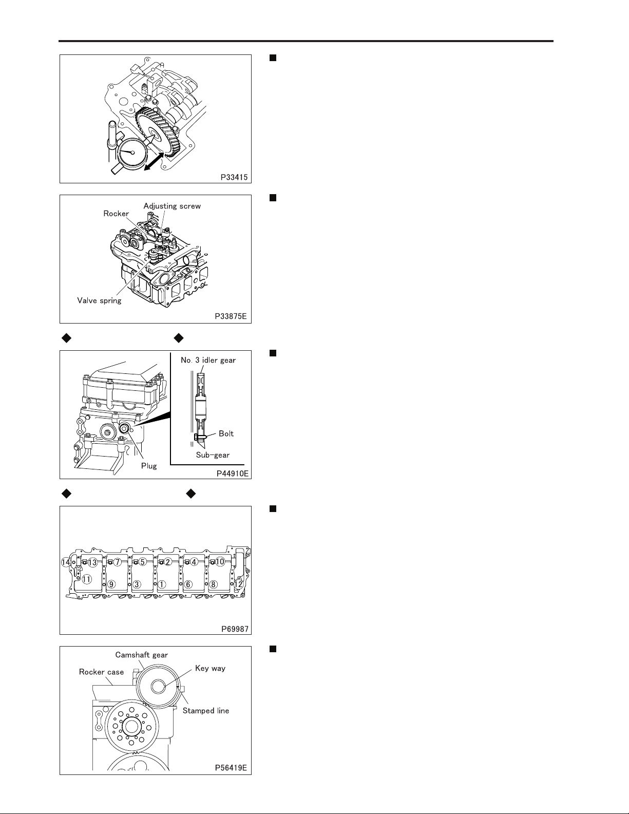
Inspection: Camshaft end play
• If the measurement exceeds the limit, replace the defective
part(s).
Releasing valve spring force
• Before loosening the rocker and bracket assembly mounting
bolts, check whether the valve springs are compressed by the
rockers. If so, loosen the adjusting screws on the rockers to relieve the spring force. This will eliminate the possibility of compressed springs damaging parts when they are released.
Removal procedure
Installation procedure
Removal: Camshaft
• Remove the plug at the rear end of the cylinder head.
• Insert a sub-gear locking bolt (M8 × 1.25 mm, length 20 mm) into
the dedicated hole in the No. 3 idler gear to lock the sub-gears.
Remove the camshaft.
Installation: Rocker case
• Tighten the rocker case bolts in the order shown in the illustra-
tion.
11-18
Installation: Camshaft
• Make sure that the timing marks on the timing gears are aligned
with each other.
• Install the camshaft so that the stamped line on the camshaft
gear is level with the top surface of the rocker case.
• Install the plug at the rear end of the cylinder head. (See later
pages.)
Page 19
11
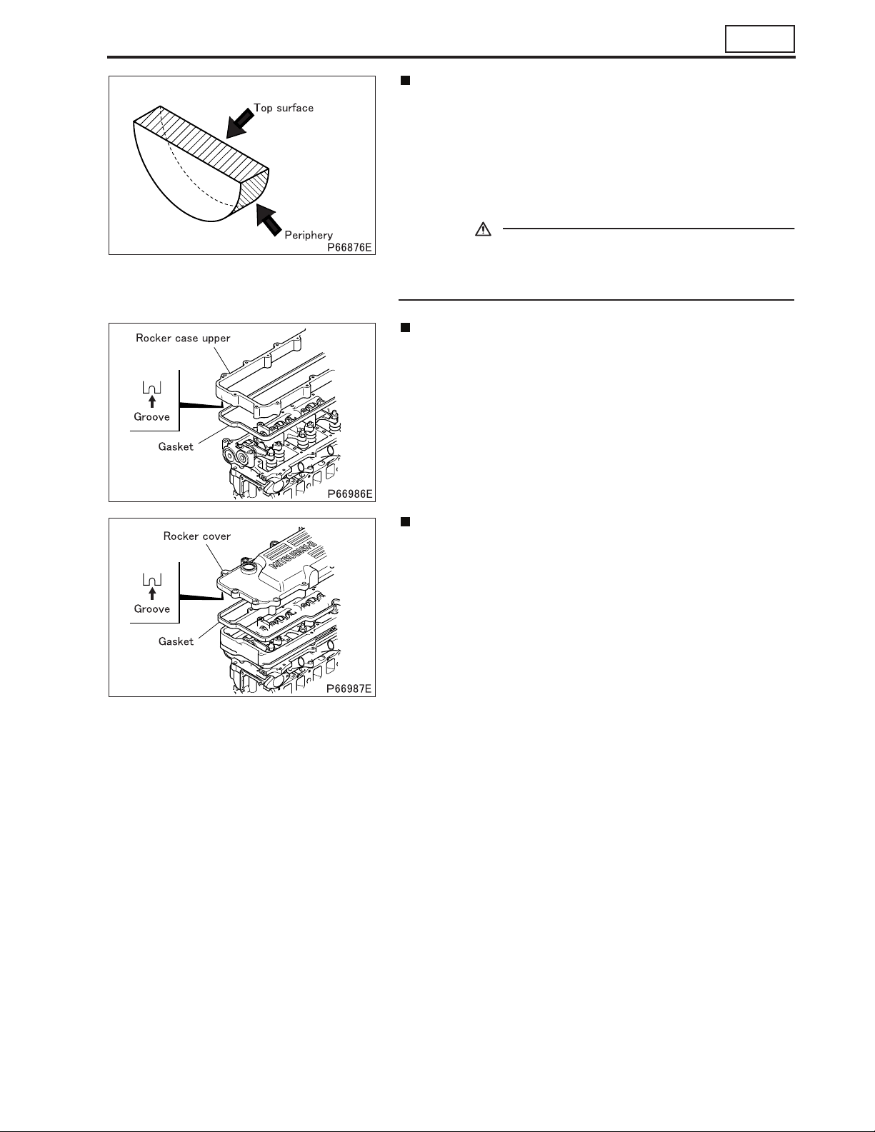
Installation: Packing
• Apply sealant onto the peripheral surface of the packing.
• Immediately after the sealant application, install the packing to
the rocker case.
• After installing it on the rocker case, apply sealant to the top surface of the packing.
• Immediately after the sealant application, install the rocker case
upper and rocker case upper gasket in place.
CAUTION
• Do not start the engine for one hour after installation.
• When removing the rocker cover after installation, never fail
to apply sealant again.
Installation: Rocker case upper gasket
• Make sure that the gasket fitting groove in the rocker case is
clear of grease and dirt. Clean if necessary.
• Before installation, make sure that the gasket is free of grease,
etc. that could cause an oil leakage.
Installation: Rocker cover gasket
• Make sure that the gasket fitting groove in the rocker cover is
clear of grease and dirt. Clean if necessary.
• Before installation, make sure that the gasket is free of grease,
etc. that could cause an oil leakage.
11-19
Page 20
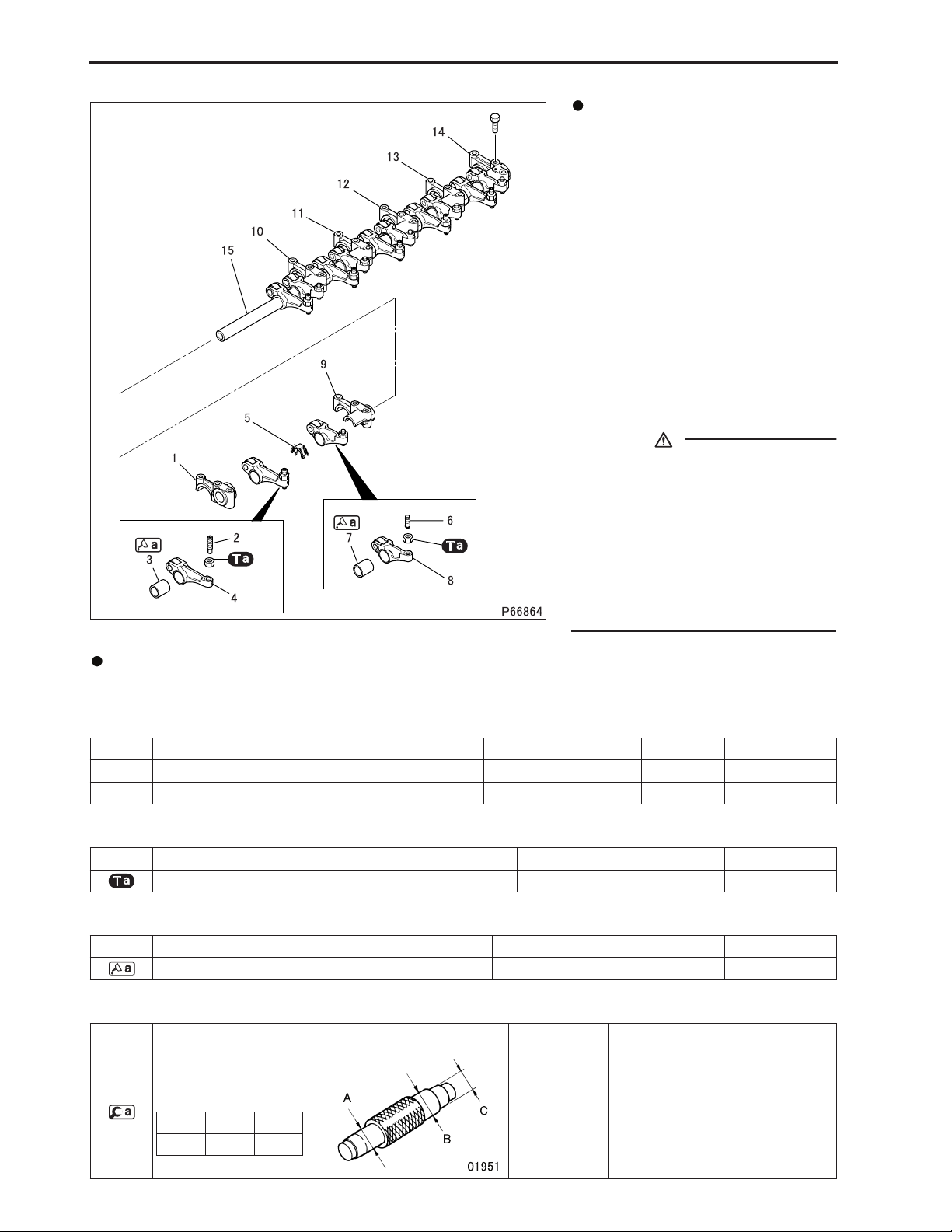
ROCKER COVER, ROCKER BRACKET AND CAMSHAFT
Rocker and Bracket Assembly
Disassembly sequence
1 Front bracket
2 Adjusting screw
3 Rocker bushing
4 Intake rocker
5 Rocker shaft spring
6 Adjusting screw
7 Rocker bushing
8 Exhaust rocker
9 No. 1 center bracket
10 No. 2 center bracket
11 No. 3 center bracket
12 No. 4 center bracket
13 No. 5 center bracket
14 Rear bracket
15 Rocker shaft
CAUTION
• The rocker and bracket assembly
and the rocker case are assembled
together with precise adjustment
and therefore they cannot be replaced separately.
If the rocker and bracket assembly
is to be reused, be sure to reassemble the assembly with the same
combinations of its parts as before.
Assembly sequence
Follow the disassembly sequence in reverse.
Service standards (Unit: mm)
Location Maintenance item Standard value Limit Remedy
3, 7, 15 Clearance between rocker shaft and bushing 0.006 to 0.076 0.114 Replace
4, 8 Radial clearance of rocker (roller) 0.035 to 0.078 – Replace
Tightening torque (Unit: N·m {kgf·m})
Mark Parts to be tightened Tightening torque Remarks
Lock nut (adjusting screw tightening) 34 {3.5} –
Lubricant and/or sealant
Mark Points of application Specified lubricant and/or sealant Quantity
Inside surface of rocker bushing Engine oil As required
Special tools (Unit: mm)
Mark Tool name and shape Part No. Application
Rocker bushing puller
ABC
φ 25 φ 27.5 φ 25
MH062727
Removal and installation of rocker
bushing
11-20
Page 21
Inspection procedure
11
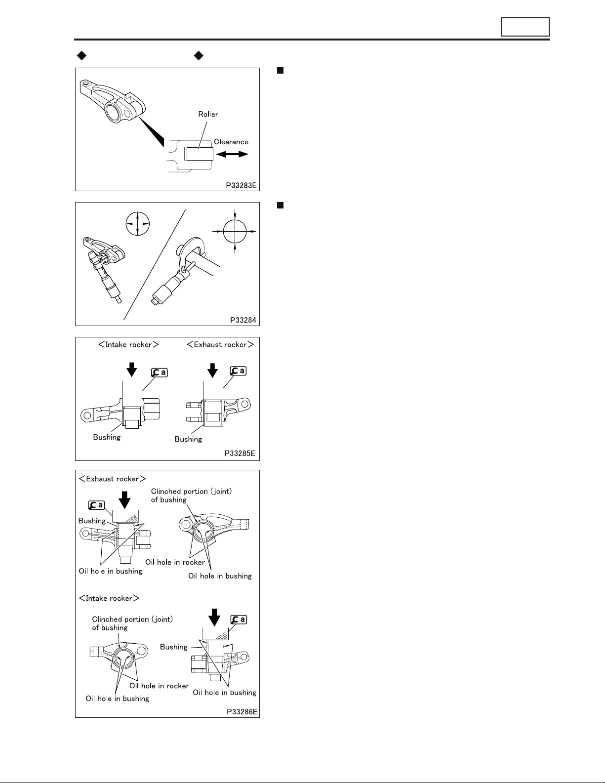
Inspection: Radial clearance of rocker (roller)
• If the measurement deviates from the standard value, replace
the defective part(s).
Inspection: Clearance between rocker shaft and bushing
• If the measurement exceeds the limit, replace the bushing.
Replace of rocker bushing
[Removal]
[Installation]
• Assemble the bushing onto the rocker such that the oil holes are
aligned as shown in the illustration.
• After assembly, recheck the clearance.
• If the measurement is less than the standard value, ream the
bushing.
11-21
Page 22
ROCKER COVER, ROCKER BRACKET AND CAMSHAFT
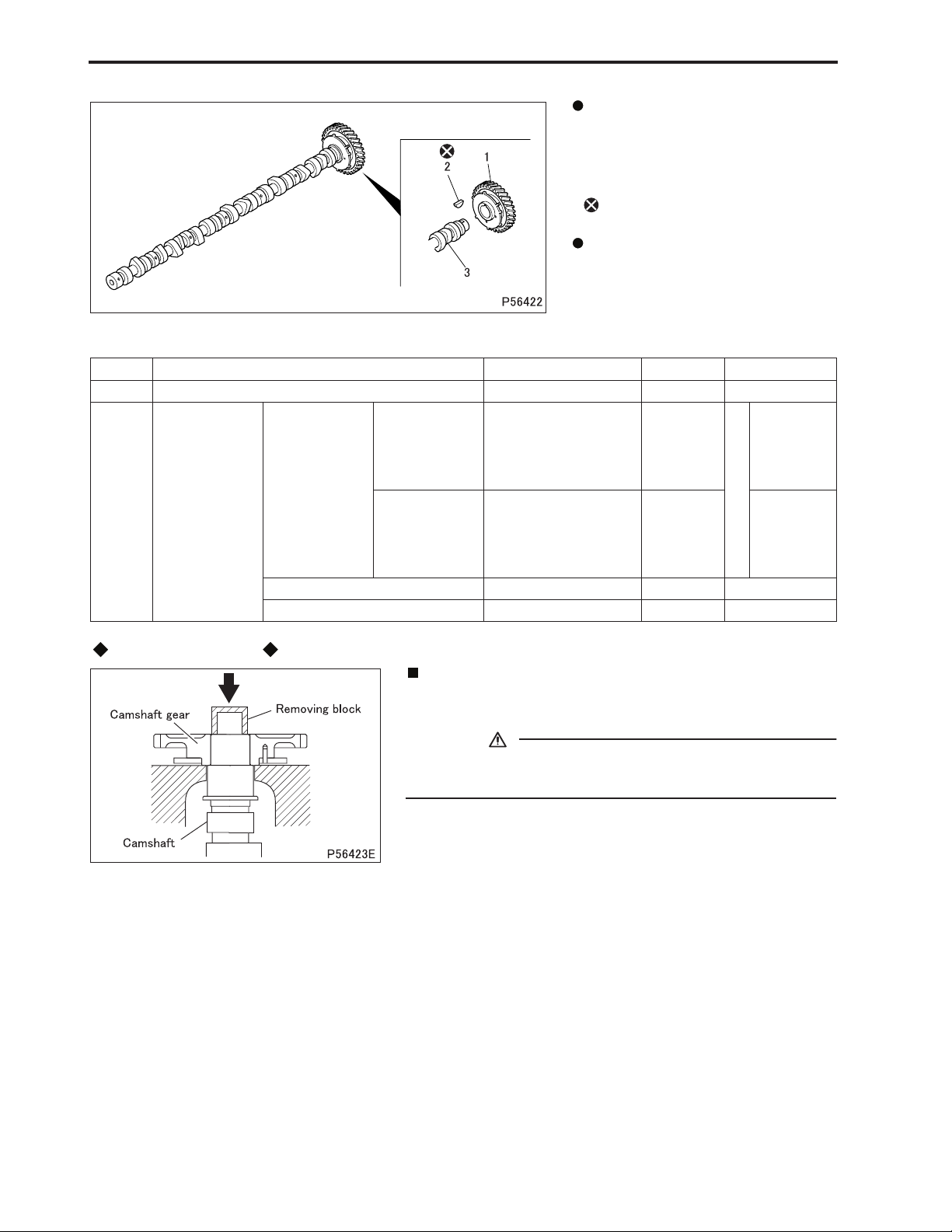
Camshaft
Disassembly sequence
1 Camshaft gear
2 Key
3 Camshaft
: Non-reusable parts
Assembly sequence
Follow the disassembly sequence in reverse.
Service standards (Unit: mm)
Location Maintenance item Standard value Limit Remedy
1, 3 Interference between camshaft gear and camshaft 0.017 to 0.062 – Replace
Lobe diameter: 45.110
Intake 5.023 4.973
Cam lift
3 Camshaft
Exhaust 7.084 7.034
Bend 0.02 or less 0.04 Replace
Oil clearance at journal 0.075 to 0.12 0.25 Inspect
Base circle
diameter:
Lobe diame-
Replace
ter: 47.370
Base circle
diameter:
40.087
40.286
Removal procedure
Removal: Camshaft gear
• Remove the camshaft gear by pushing on the end of the cam-
shaft with a press or other similar tool.
CAUTION
• Do not attempt to remove the camshaft gear with a hammer
as damage will result. Use a press or other similar tool.
11-22
Page 23
Inspection procedure
11
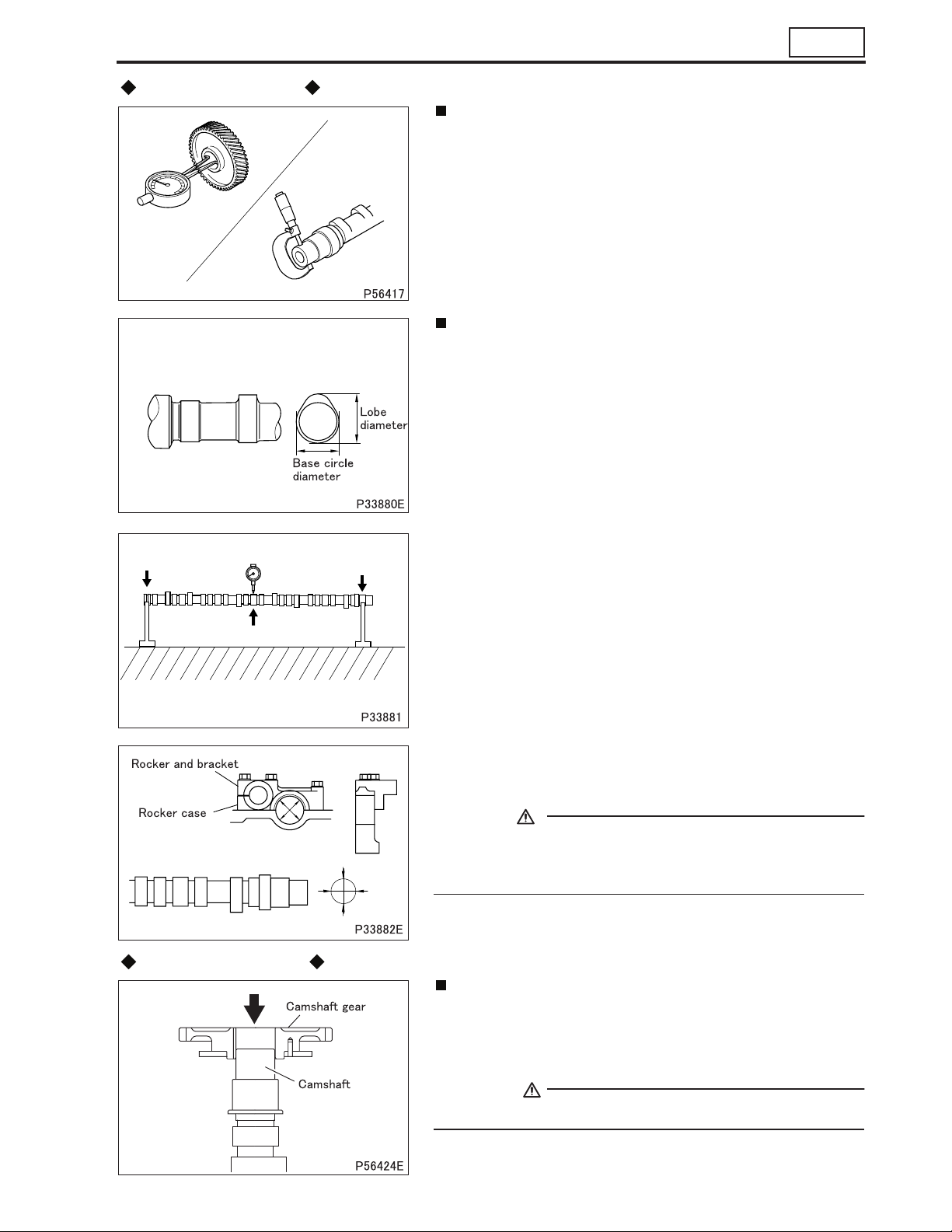
Inspection: Interference between camshaft gear and camshaft
• If the measurement deviates from the standard value, replace
the defective part(s).
Inspection: Camshaft
(1) Cam lift
• If the measurement (difference between lobe diameter and base
circle diameter) is less than the limit, replace the camshaft.
Installation procedure
(2) Bend
• Measure the camshaft at the center journal for bend while sup-
porting the shaft at the end journals.
• A half of the dial gauge reading obtained as the camshaft is rotated by a full turn represents the bend of the camshaft.
• If the measurement exceeds the limit, replace the camshaft.
(3) Oil clearance at journal
• If the measurement exceeds the limit, replace the defective
part(s).
CAUTION
• The rocker case and the brackets of the rocker and bracket
assembly have been machined together, which means that
they all must be replaced together.
Installation: Camshaft gear
• Heat the camshaft gear to approximately 150°C using a gas
burner.
• While facing the camshaft gear as shown in the illustration,
press it onto the camshaft until it seats snugly on the camshaft.
WARNING
• The camshaft is extremely hot. Be careful not to touch it.
11-23
Page 24
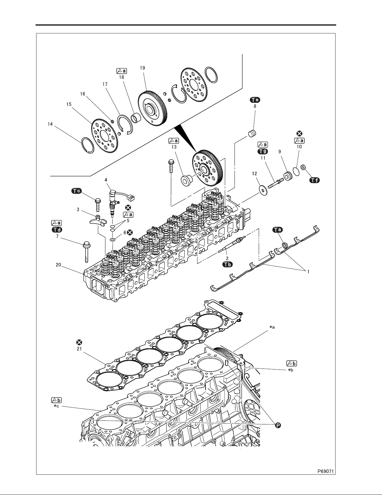
CYLINDER HEAD AND VALVE MECHANISM
11-24
Page 25
11
Disassembly sequence
1 Connecting plate
2 Glow plug
3 Nozzle bridge
4 Injector (See Gr13A.)
5 O-ring
6 Nozzle tip gasket
7 Cylinder head bolt
8 Plug
9 Collar
10 O-ring
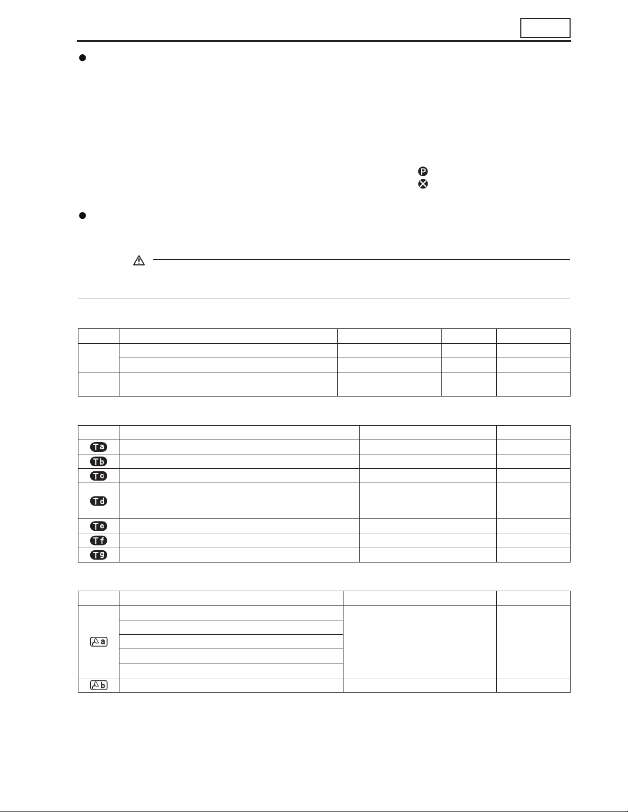
Assembly sequence
Follow the disassembly sequence in reverse.
CAUTION
• After the No. 3 idler gear has been reassembled onto the cylinder head, remove the locking bolt from the
sub-gears.
Service standards (Unit: mm)
Location Maintenance item Standard value Limit Remedy
Backlash between No. 3 and No. 2 idler gears 0.17 to 0.25 0.35 Replace
–
No. 3 idler gear end play 0.05 to 0.15 0.3 Replace
13, 18
Clearance between No. 3 idler shaft and No. 3 idler
gear bushing
11 No. 3 idler bolt
12 Thrust plate
13 No. 3 idler shaft
14 Snap ring
15 Sub-gear
16 Pin
17 Spring
18 No. 3 idler gear bushing
19 No. 3 idler gear
0.01 to 0.05 0.2 Replace
20 Cylinder head
(See later section.)
21 Cylinder head gasket
a: No. 2 idler gear
*
b: Flywheel housing
*
c: Crankcase
*
: Locating pin
: Non-reusable parts
Tightening torque (Unit: N·m {kgf·m})
Mark Parts to be tightened Tightening torque Remarks
Nut (connecting plate mounting) 1.0 to 1.5 {0.1 to 0.15} –
Glow plug 20 to 25 {2.0 to 2.5} –
Bolt (nozzle bridge mounting) 33 to 38 {3.4 to 3.9} –
Cylinder head bolt 78 {8} + 90° + 90°
Plug 13 to 17 {1.3 to 1.7} –
Nut (collar mounting) 39 to 59 {4.0 to 6.0} –
No. 3 idler bolt 59 to 78 {6.0 to 8.0} –
+5°
0
+5°
• Wet
• Reusable up
0
to 3 times
Lubricant and/or sealant
Mark Points of application Specified lubricant and/or sealant Quantity
Threaded portion of cylinder head bolt
O-ring
Threaded portion of No. 3 idler bolt
Periphery of No. 3 idler shaft
Inside surface of No. 3 idler gear bushing
Top mating surfaces of flywheel housing and crankcase ThreeBond 1207F As required
Engine oil As required
11-25
Page 26
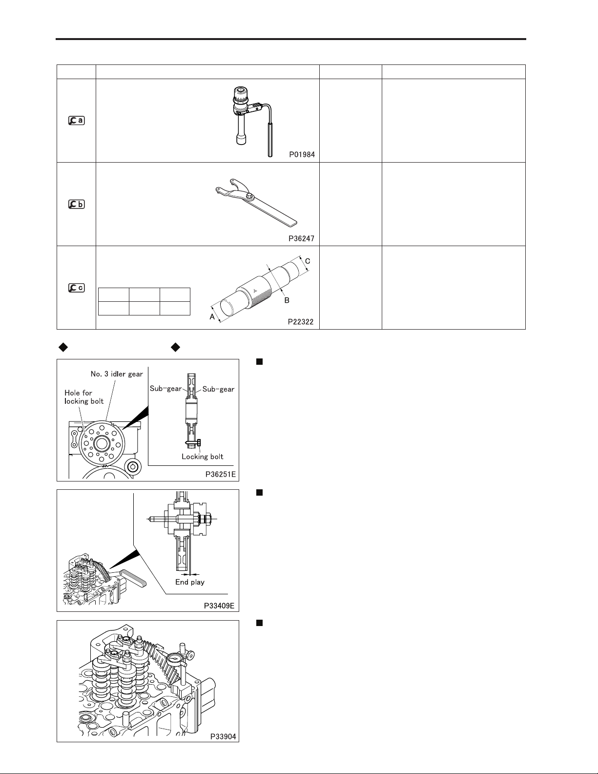
CYLINDER HEAD AND VALVE MECHANISM
Special tools (Unit: mm)
Mark Tool name and shape Part No. Application
Socket wrench MH063388 Installation of cylinder head
Pin wrench arm MH063473 Assembly of No. 3 idler gear
Idler gear push-puller
ABC
φ 32 φ 35 φ 32
Work before removal
MH061779
Locking sub-gears
• Before removing the No. 3 idler gear, install a locking bolt (M8 ×
1.25 mm, length 20 mm) into the dedicated hole to lock the subgears.
Inspection: End play of No. 3 idler gear
• If the measurement exceeds the limit, replace the defective
part(s).
Removal and installation of No. 3 idler
gear bushing
11-26
Inspection: Backlash between No. 2 and No. 3 idler gears
• If the measurement exceeds the limit, replace the defective
part(s).
Page 27
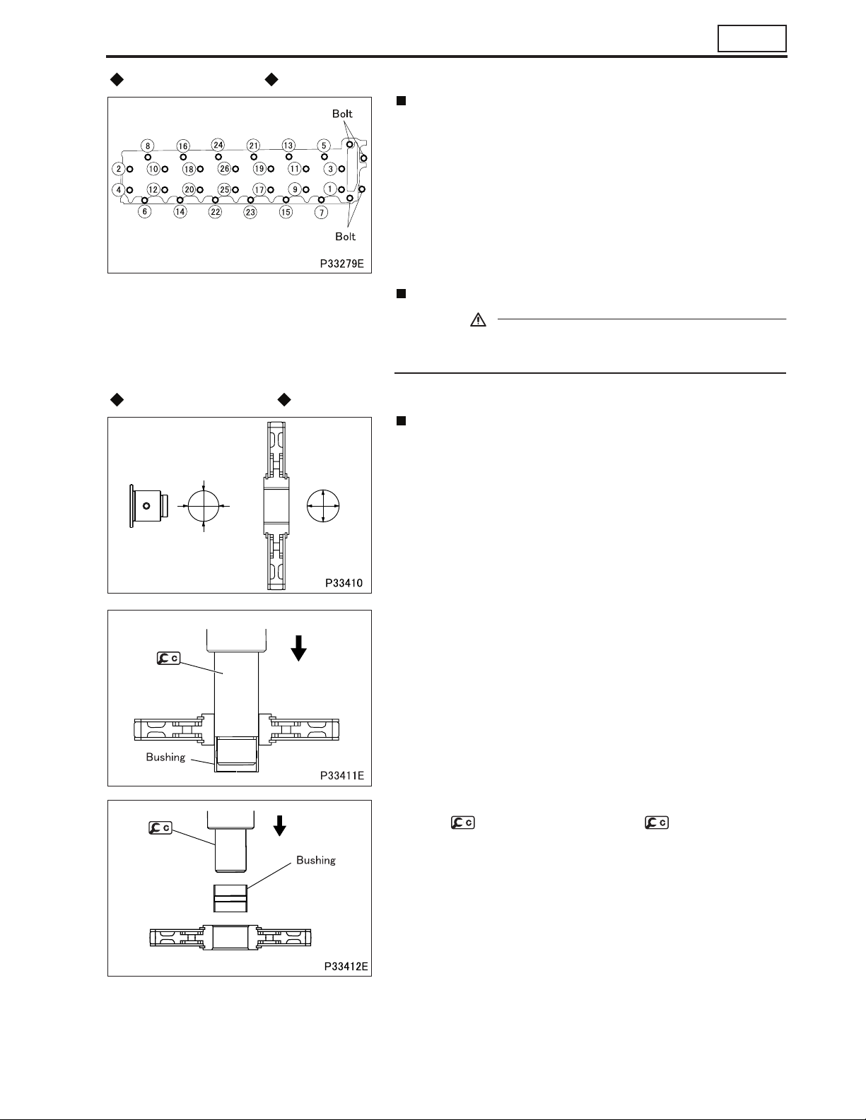
Removal procedure
Inspection procedure
11
Removal: Cylinder head
• Remove the bolts (× 4).
• Progressively loosen the cylinder head bolts in the order shown
in the illustration, going over them several times, before eventually removing them.
Removal: Cylinder head gasket
CAUTION
• Be careful not to scratch the cylinder head, crankcase and
flywheel housing when removing the cylinder head gasket.
Inspection: Clearance between No. 3 idler shaft and No. 3
idler gear bushing
• If the measurement exceeds the limit, replace the bushing.
Replacement of No. 3 idler gear bushing
[Removal]
[Installation]
• Using , press in the bushing until contacts the No. 3
idler gear.
• After installation, measure the clearance again.
• If the measurement is lower than the standard value, ream the
bushing.
11-27
Page 28

CYLINDER HEAD AND VALVE MECHANISM
Installation procedure
Installation: Sub-gears
• Install the No. 3 idler gear on a vice. Use shop towel to protect
the gear from direct contact with the vice.
• Install a sub-gear, a spring and pins on one side of the No. 3
idler gear.
• Hook each end A of the spring on a pin.
• Install a snap ring.
• Using , turn the sub-gear clockwise until the countermark
on the sub-gear is aligned with the stamped line on the No. 3
idler gear. Then, install a locking bolt (M8 × 1.25 mm, 20 mm
long) into the dedicated hole.
• Turn over the No. 3 idler gear and repeat the same procedure on
the other side of the No. 3 idler gear, installing another sub-gear,
a spring, pins and a snap ring.
Installation: Cylinder head
CAUTION
• Before fitting the cylinder head bolts, check the punch
marks on each bolt’s head. Do not use the bolt if there are
three punch marks.
The punch marks indicate the number of times each bolt
has been tightened using the torque-turn tightening method. Any bolt that already has three punch marks must be replaced.
11-28
Page 29
11
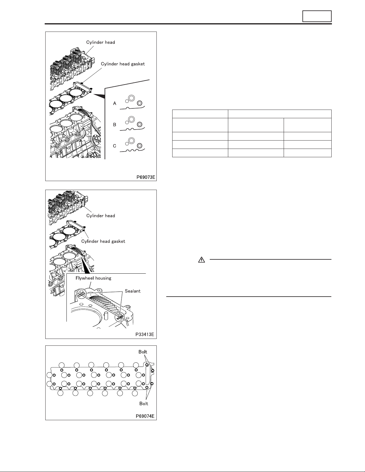
• The cylinder head gasket is a part that needs to be selected for
use. Choose the appropriate gasket in the following manner.
• Measure the piston protrusion from each cylinder. (See Piston.)
• Then, from the table below, choose the cylinder head gasket
having a thickness appropriate to the average protrusion of the
pistons.
• If the cylinder head has even one cylinder that exceeds the largest of the measured piston protrusions by 0.05mm or more, use
a gasket at least one size larger in thickness
(A → B, B → C).
Unit: mm
Piston protrusion Cylinder head gasket
Average piston
protrusion
0.804 to 0.872 A(1) 1.70 ± 0.05
0.873 to 0.941 B(2) 1.75 ± 0.05
0.942 to 1.011 C(3) 1.80 ± 0.05
• Identify the appropriate type of cylinder head gasket according
to the number of notches in its notched end.
Type by size
( ): No. of notches
Tightened
thickness
• Remove oil and any other contamination from the surfaces
where sealant is to be applied.
• Apply sealant onto the surfaces of the flywheel housing and
crankcase that will be fitted together.
• Within three minutes following the sealant application, install the
cylinder head onto the crankcase, with the cylinder head gasket
in between them, using the cylinder head bolts. Take care so
that the applied sealant is not displaced during installation.
Be sure to install the gasket in the illustrated position.
CAUTION
• Do not start the engine for at least an hour after installation.
• Whenever cylinder head bolts are loosened or removed after installation, the cylinder head gasket must be replaced
and sealant reapplied.
• Tighten the cylinder head bolts to a torque of 78N.m {8kgf.m} in
the order shown in the illustration.
19
25
17
15
23
21
3
11
1
9
2
7
13
5
14
6
8
10
4
22
24
16
26
18
12
20
• Further tighten the bolts in the illustrated order as follows.
11-29
Page 30
CYLINDER HEAD AND VALVE MECHANISM
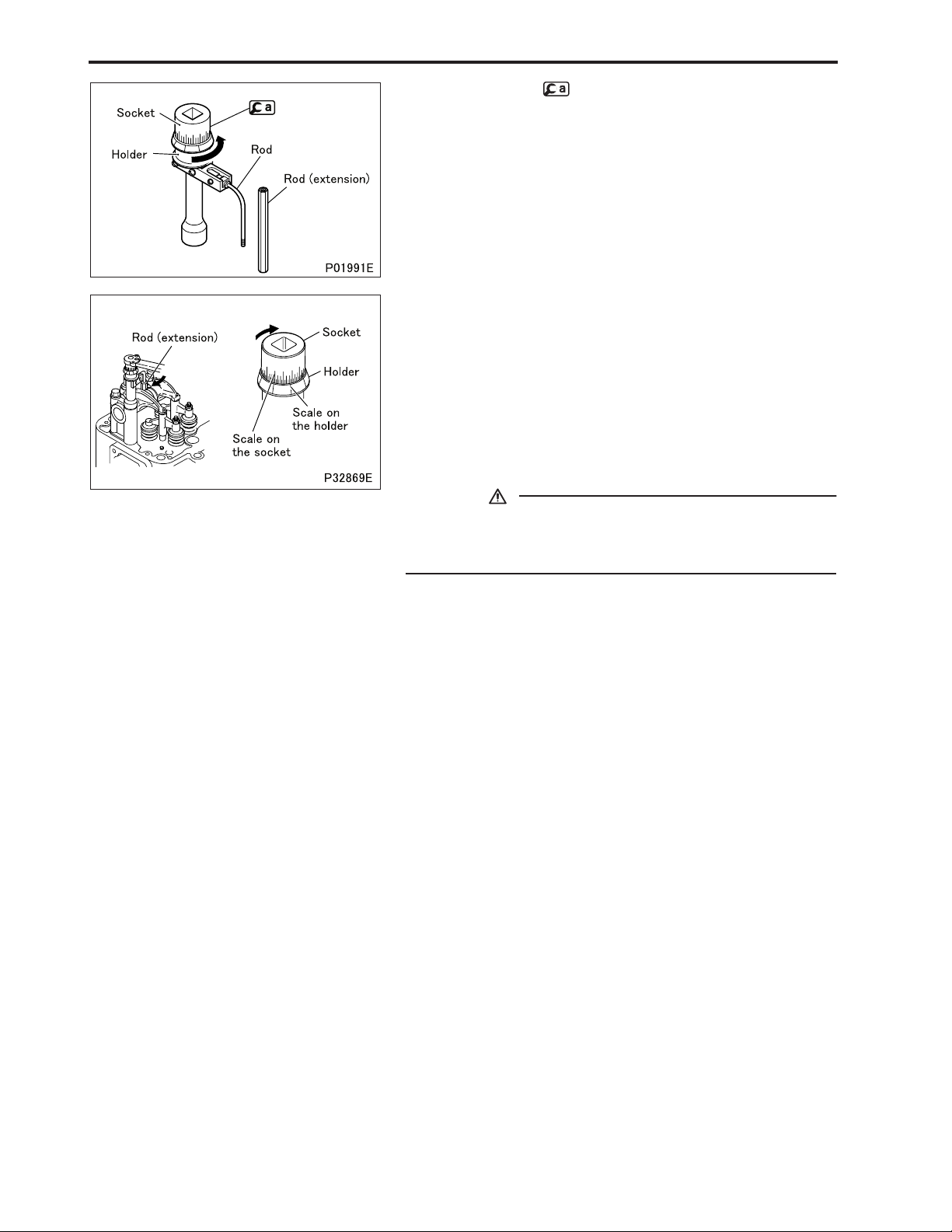
• Turn the holder of counterclockwise to pretension the inter-
nal spring.
• Set
the tool such that the rod (extension) is pressed against the
rocker shaft bracket by the force of the spring.
• Align any line on the holder scale with any line on the socket
scale. (This will be used as the reference point = 0°.)
• From the reference point, turn the socket by 90° in the direc-
tion shown. Each division on the holder scale represents 5°.
• Further turn the socket by 90° .
• After tightening the cylinder head bolts within the plastic region,
punch a mark on the bolt heads to record the number of times
that they have been tightened.
CAUTION
• Cylinder head bolts that have been tightened using the
torque-turn method must never be additionally tightened after the final angular tightening.
+5°
+5°
0
0
11-30
Page 31

M E M O
11
11-31
Page 32
CYLINDER HEAD AND VALVE MECHANISM
Cylinder Head
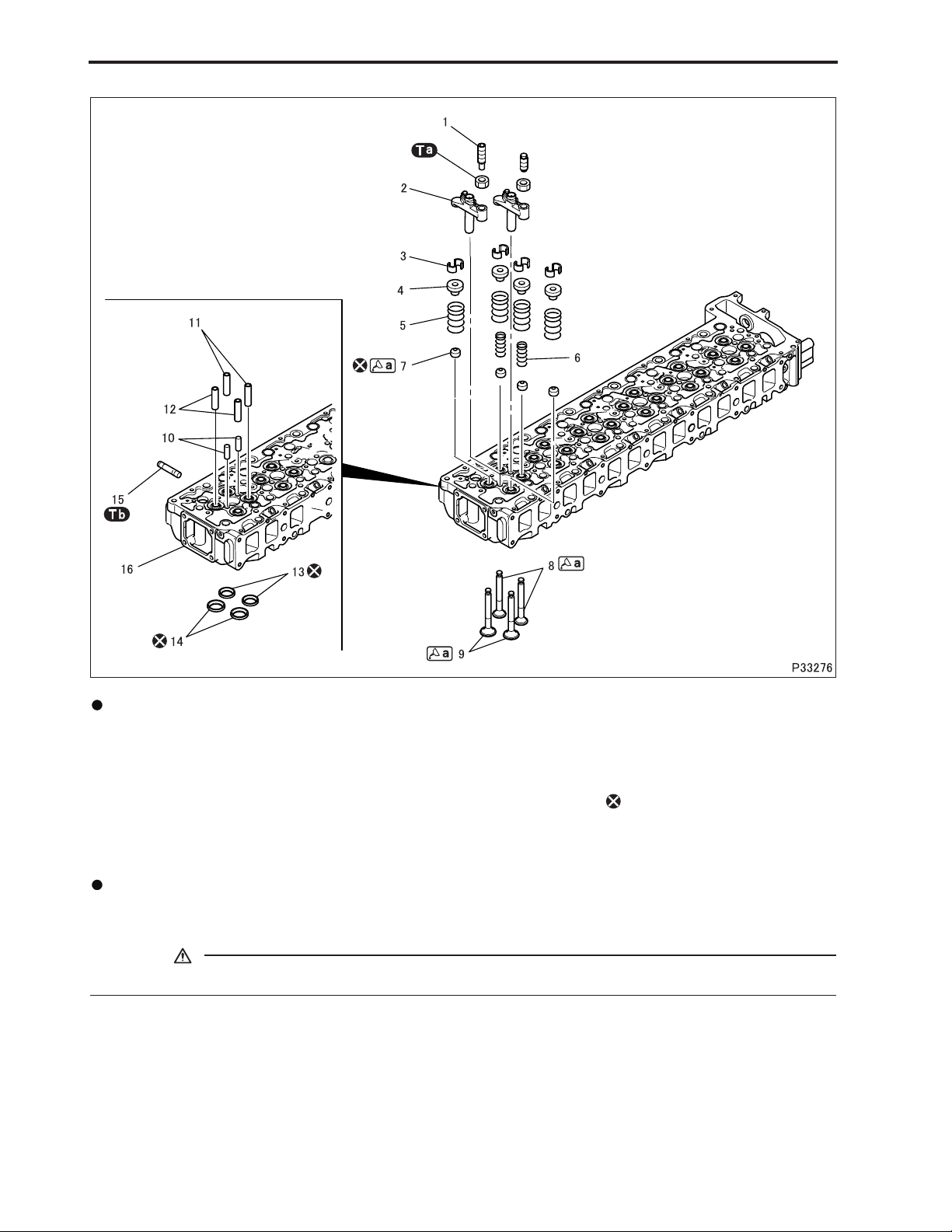
Disassembly sequence
1 Adjusting screw
2 Valve bridge
3 Valve cotter
4 Upper retainer
5 Outer valve spring
6 Inner valve spring
<Only exhaust valve>
7 Valve stem seal
8 Exhaust valve
9 Intake valve
10 Valve bridge guide
11 Exhaust valve guide
12 Intake valve guide
13 Exhaust valve seat
14 Intake valve seat
15 Stud bolt
16 Cylinder head
: Non-reusable parts
Assembly sequence
Follow the disassembly sequence in reverse.
CAUTION
• When an exhaust valve or intake valve has been removed, make sure to replace the valve stem seal.
11-32
Page 33
Service standards (Unit: mm)
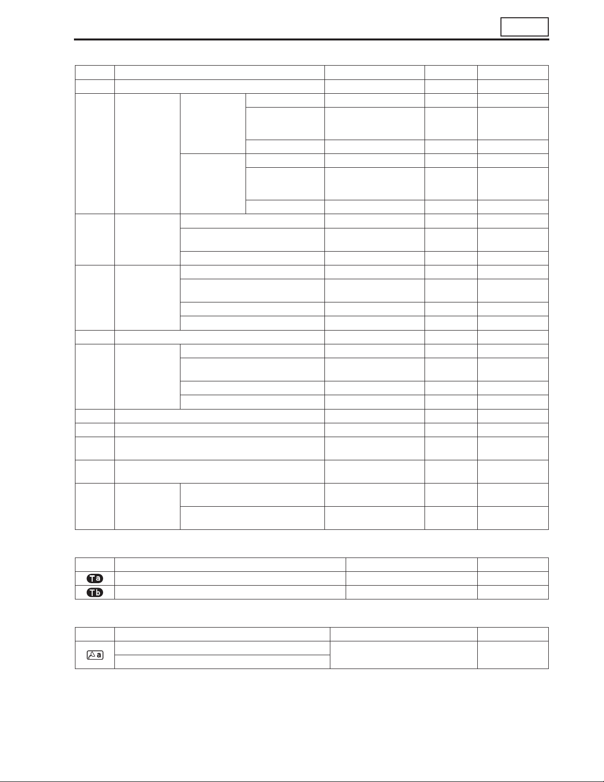
Location Maintenance item Standard value Limit Remedy
2, 10 Valve bridge-to-valve bridge guide clearance 0.01 to 0.04 0.1 Replace
Free length 71.7 68.1 Replace
Intake side
Outer valve
5
spring
Exhaust side
Free length 60.61 57.6 Replace
Inner valve
6
spring
8 Exhaust valve
8, 11 Exhaust valve stem-to-valve guide clearance 0.07 to 0.10 0.2 Replace
9 Intake valve
9, 12 Intake valve stem-to-valve guide clearance 0.06 to 0.09 0.2 Replace
10 Valve bridge guide in outside diameter 9.989 to 10 9.94 Replace
13 Exhaust valve seat width 2.3 to 2.7 3.3
14 Intake valve seat width 1.8 to 2.2 2.8
16 Cylinder head
Installed load
(41.8 in installed length)
Squareness – 2° or less Replace
Stem outside diameter φ8 φ7.85 Replace
Sinkage from cylinder head
bottom surface
Valve margin 1.5 1.2 Replace
Seat angle 45° ± 15’ – Correct
Stem outside diameter φ8 φ7.85 Replace
Sinkage from cylinder head bottom
surface
Valve margin 1.5 1.2 Replace
Seat angle 45° ± 15’ – Correct
Bottom surface distortion 0.08 or less 0.2
Height from top surface to
bottom surface
Installed load
(46.5 in installed
length)
Squareness – 2° or less Replace
Free length 66.47 63.1 Replace
Installed load
(46.5 in installed
length)
Squareness – 2° or less Replace
407 ± 20.6 N
{42 ± 2.1 kgf}
280 ± 14 N
{29 ± 1.4 kgf}
127 ± 6.3 N
{12.9 ± 1.9 kgf}
–0.060
–0.075
1.3 ± 0.2 1.55 Inspect
–0.025
–0.040
1.3 ± 0.2 1.55 Inspect
94.9 to 95.1 94.5 Replace
367 N
{37 kgf}
252 N
{26 kgf}
121 N
{12 kgf}
Replace
Replace
Replace
Correct or
replace
Correct or
replace
Correct or
replace
11
Tightening torque (Unit: N·m {kgf·m})
Mark Parts to be tightened Tightening torque Remarks
Lock nut (valve bridge adjusting screw tightening) 59 {6.0} –
Stud bolt 20 {2} –
Lubricant and/or sealant
Mark Points of application Specified lubricant and/or sealant Quantity
Lip of valve stem seal
Stem and end of valve
Engine oil As required
11-33
Page 34
CYLINDER HEAD AND VALVE MECHANISM
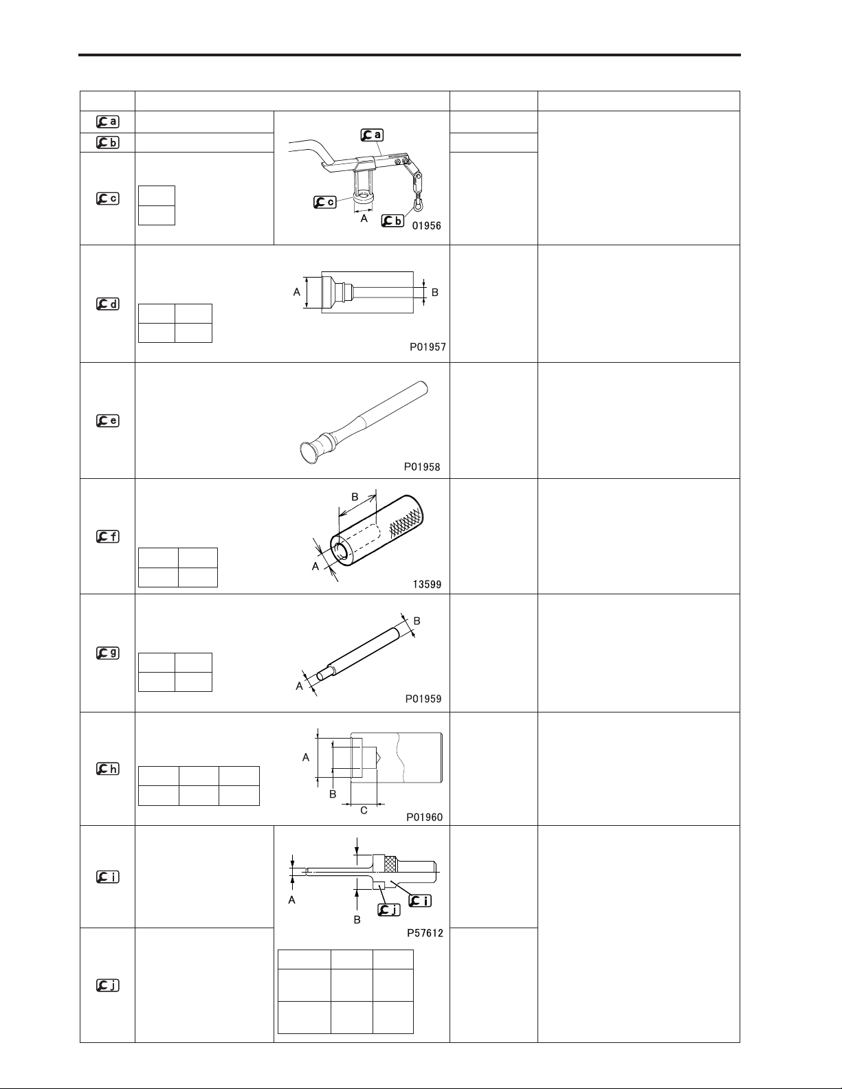
Special tools (Unit: mm)
Mark Tool name and shape Part No. Application
Valve lifter
Valve lifter hook MH061679
MH061668
Valve lifter seat
A
φ 38
Valve stem seal installer
AB
φ 25 φ 9
Valve lapper 30091-07500 Lapping valves and valve seats
Valve bridge guide
installer
AB
φ 10 37.2
MH061772
MH062689 Installation of valve stem seals
MH062724 Installation of valve bridge guides
Removal and installation of valve cotters
Valve guide remover
AB
φ 8 φ 12
Valve guide installer
ABC
φ 25.5 φ 13 17
Caulking tool body 31391-13100
AB
Installer ring
Intake
valve
Exhaust
valve
φ 8 φ 42
φ 8 φ 38
31391-10500 Removal of valve guides
MH062726 Installation of valve guides
MH062725
<Intake valve>
MH063605
<Exhaust valve>
Installation of valve seat
11-34
Page 35
Removal procedure
Inspection procedure
11
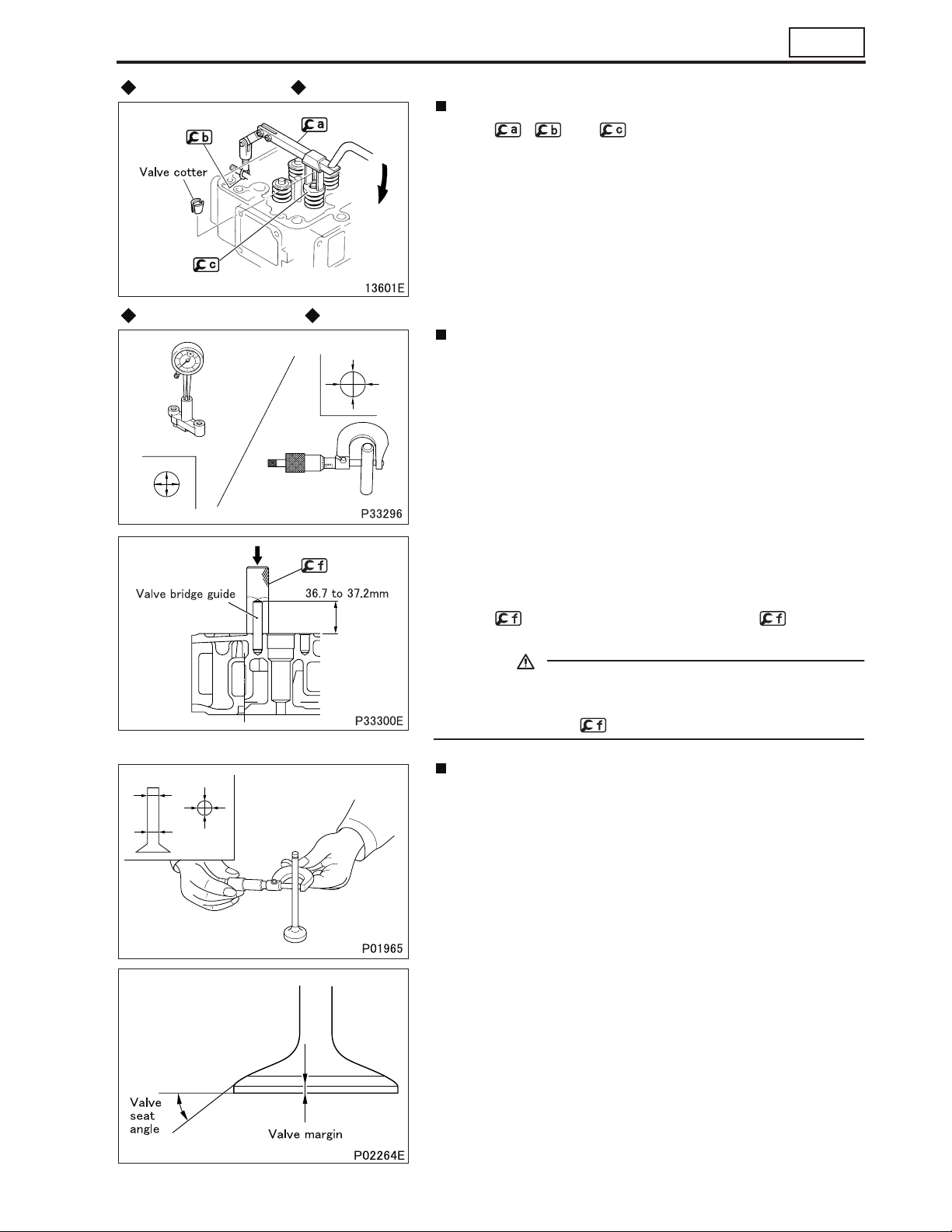
Removal: Valve cotters
• Using , and , remove the valve cotter while com-
pressing the valve spring(s) evenly.
Inspection: Valve bridge and valve bridge guide
(1) Valve bridge-to-guide clearance
• If the measurement exceeds the limit, replace the defective
part(s).
(2) Outside diameter of valve bridge guide
• If the measurement is less than the limit or the valve bridge
guide is worn extremely unevenly, replace the valve bridge
guide.
Replacement of valve bridge guide
[Installation]
• Before installation, ensure that no water, oil or other foreign mat-
ter is in the installation hole.
• Using , install the valve bridge guide until comes into
positive contact with the cylinder head.
CAUTION
• The valve bridge guide must be installed to the specified
depth of the cylinder head. Correct installation can only be
possible by using .
Inspection: Intake and exhaust valve
(1) Valve stem outside diameter
• Replace the valve if the stem’s outside diameter is below the
limit or is severely worn.
• When the valve has been replaced with a new one, make sure
to lap the valve and valve seat.
(2) Valve seat angle and valve margin
• Reface or replace the valve if the valve seat angle or valve mar-
gin exceeds the specified limits.
• After refacing or replacing the valve seat, make sure to lap the
valve and valve seat.
11-35
Page 36
CYLINDER HEAD AND VALVE MECHANISM
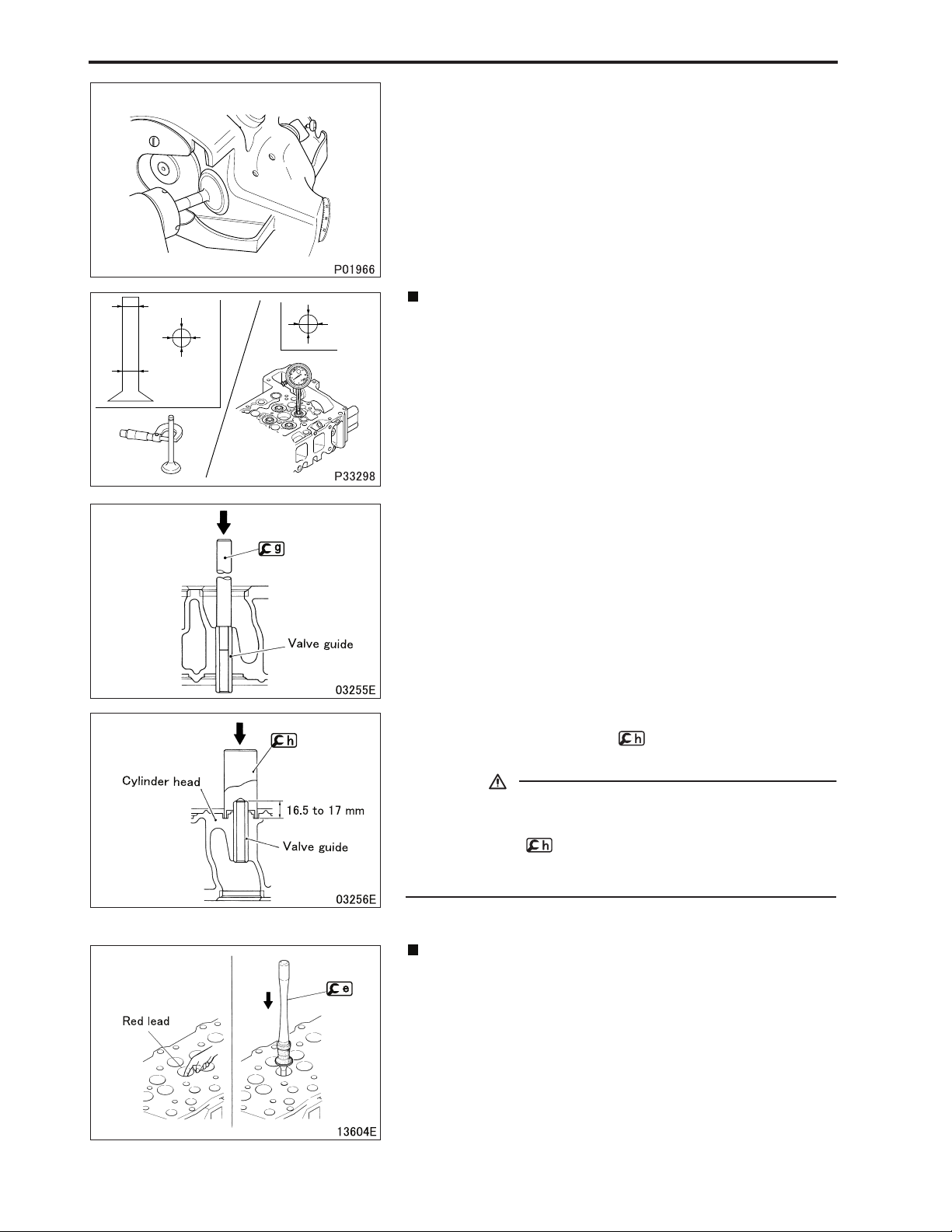
Refacing
• Limit grinding to a necessary minimum.
• If the valve margin is below the limit after grinding, replace the
valve.
• After grinding, make sure to lap the valve and valve seat.
Inspection: Valve-to-valve guide clearance
• If the clearance exceeds the specified limit, replace the defective
part(s).
Replacement of valve guides
[Removal]
[Installation]
• Install the valve guide until sits snugly on the cylinder
head.
CAUTION
• The valve guide must protrude from the cylinder head by
the specified amount. Correct installation can only be possible by using .
• The valve guides for the exhaust valves are longer than the
valve guides for the inlet valves.
Inspection: Contact between valve and valve seat
• Before starting inspection, check that the valve and valve guide
are intact.
• Apply an even coat of red lead to the valve contact surface of
the valve seat.
• Strike the valve once against the valve seat. Do not rotate the
valve during this operation.
11-36
Page 37
11
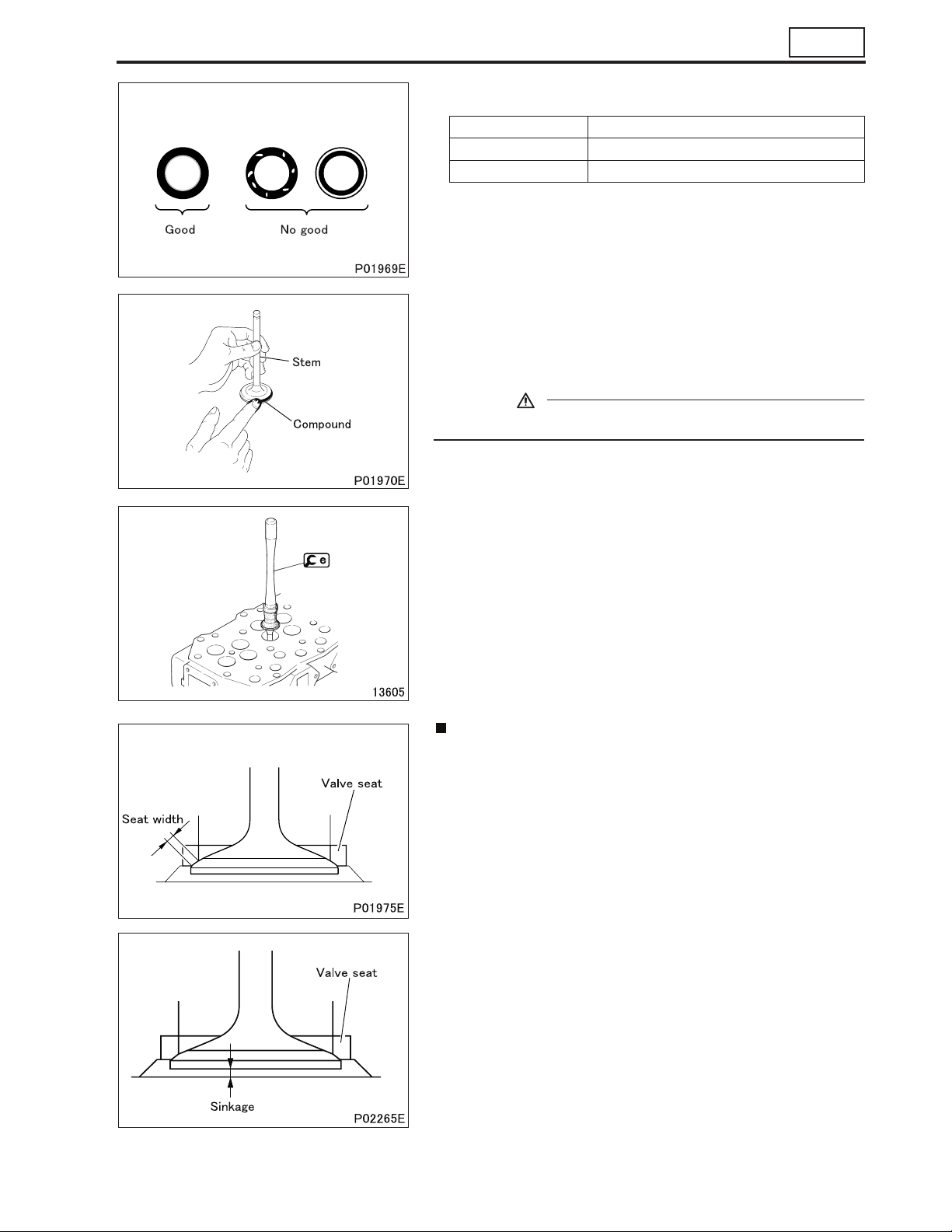
• If the red lead deposited on the valve indicates a poor contact
pattern, take either of the following corrective actions.
Contact pattern Corrective action
Minor defect Lapping
Serious defect Reface or replace valve and valve seat
Lapping
• Lap the valve in the following sequence.
• Apply a thin coat of lapping compound to the seat contact sur-
face of the valve. Adding a small amount of engine oil to the lapping compound can facilitate even application.
CAUTION
• Do not put any compound on the stem.
• Start with an intermediate-grit compound (120 to 150 grit) and
finish with a fine-grit compound (200 grit or more).
• Strike the valve several times against the valve seat while rotating the valve a little at a time.
• Wash away the compound with diesel fuel.
• Apply engine oil to the valve contact surface of the valve seat
and rub in the valve and seat well.
• Inspect the contact pattern of the valve and valve seat again.
• If the contact pattern is still defective, replace the valve seat.
Inspection: Valve seats
(1) Valve seat width
• If the measurement exceeds the limit, reface or replace the
valve seat.
• After refacing or replacing the valve seat, make sure to lap the
valve seat and valve.
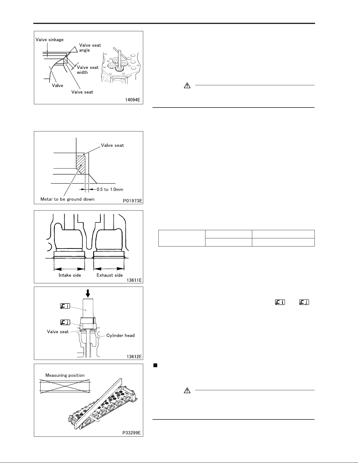
(2) Valve sinkage from cylinder head bottom surface
• Perform measurement keeping the valve in close contact with
the valve seat.
• If the measurement exceeds the limit, adjust or replace the defective part(s).
• After refacing or replacing the valve seat, make sure to lap the
valve seat and valve.
11-37
Page 38
CYLINDER HEAD AND VALVE MECHANISM
Refacing the valve seat
• Grind the valve seat using a valve seat cutter or valve seat
grinder.
• Place a piece of sandpaper of approximately #400 between the
cutter and valve seat and grind the valve seat lightly.
• Use a 15° or 75° cutter to cut the valve seat to a width within the
standard range.
CAUTION
• Make sure that the valve seat refacing does not cause the
valve sinkage to exceed the specified limit.
• Lap the valve and valve seat.
Replacement of valve seat
[Removal]
• The valve seats are installed by expansion fitting. To remove a
valve seat, grind inside the metal stock to reduce the wall thickness, then remove the valve seat at room temperature.
[Installation]
• Check that the diameters of the valve seat holes in the cylinder
head conform with the values shown below.
Diameters of the
valve seat holes
Intake side φ42 mm
Exhaust side φ38 mm
+0.025
0
+0.025
0
• Replace the cylinder head if necessary.
• Chill the valve seat thoroughly by immersing in it in liquid nitro-
gen.
• Install the valve seat in the cylinder head using and
• Lap the valve seat and valve.
Inspection: Cylinder head bottom surface distortion
• If the distortion exceeds the specified limit, rectify it using a sur-
face grinder.
CAUTION
• Make sure that the height of the cylinder head from the top
surface to the bottom surface is not reduced to a value below the specified limit.
.
11-38
Page 39
Installation procedure
11
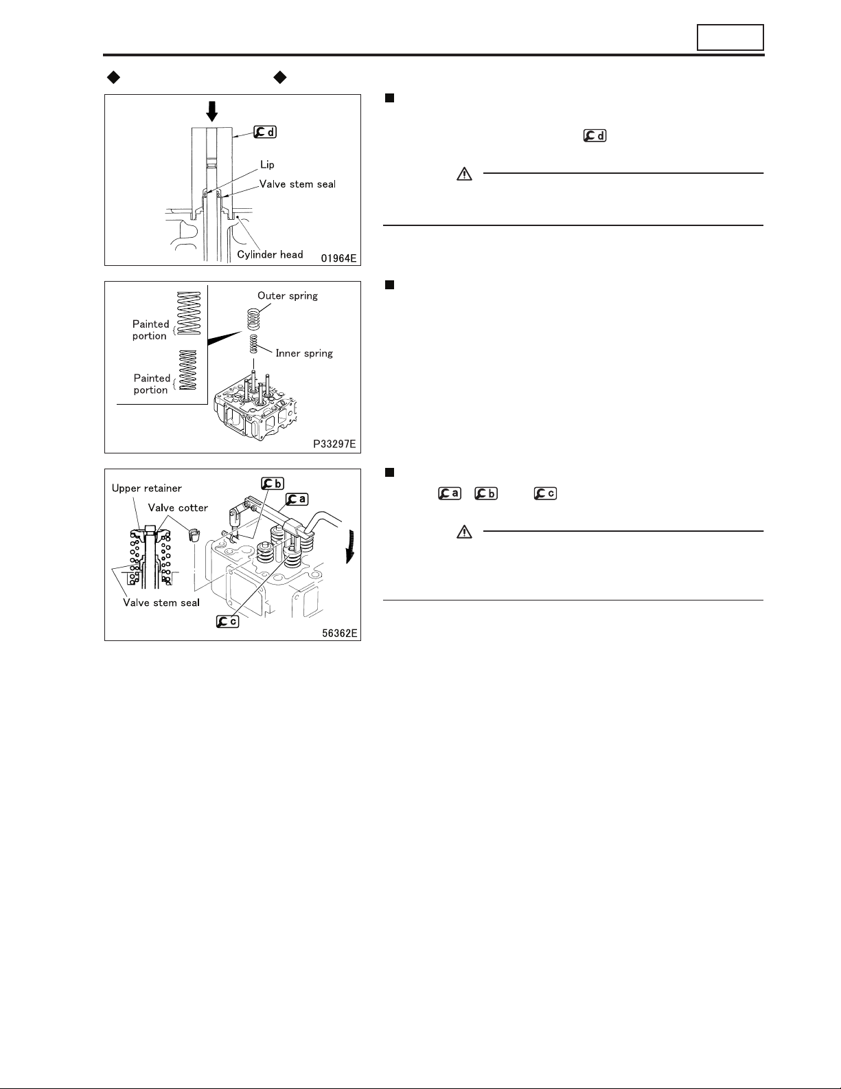
Installation: Valve stem seal
• Apply engine oil to the lip of the valve stem seal.
• Install the valve stem seal until sits snugly on the cylinder
head.
CAUTION
• After installing the valve stem seal, check that its spring is
not deformed or damaged.
Installation: Valve spring
• Install the outer and inner valve springs onto the cylinder head
while facing them as shown in the illustration.
Installation: Valve cotter
• Using , and , install the valve cotter while com-
pressing the valve spring(s) evenly.
CAUTION
• Do not compress the valve spring(s) too much, or the upper
retainer will contact the valve stem seal and damage will result.
11-39
Page 40
PISTON AND CONNECTING ROD, CYLINDER LINER
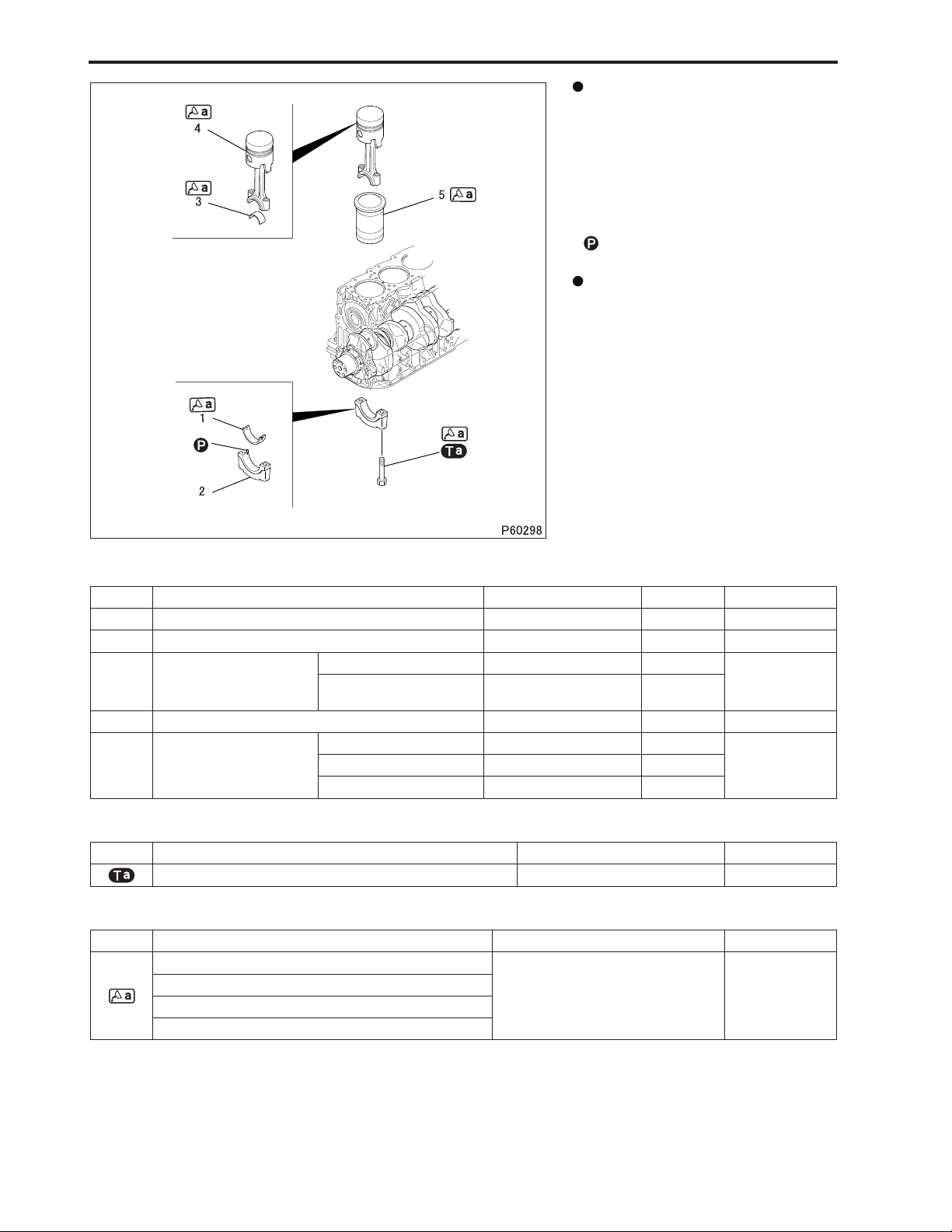
Disassembly sequence
1 Lower connecting rod bearing
2 Connecting rod cap
3 Upper connecting rod bearing
4 Piston and connecting rod
(See later sections.)
5 Cylinder liner
: Locating pin
Assembly sequence
Follow the disassembly sequence in reverse.
Service standards (Unit: mm)
Location Maintenance item Standard value Limit Remedy
– Piston projection from crankcase top surface 0.81 to 1.01 – Inspect
– Connecting rod end play 0.15 to 0.45 0.6 Inspect
Oil clearance 0.034 to 0.093 0.2
1, 3 Connecting rod bearing
4, 5 Piston and connecting rod-to-cylinder liner clearance 0.19 to 0.21 – Replace
5 Cylinder liner
Span when free –
Flange projection 0.03 to 0.10 –
Out of roundness 0.03 or less –
Less than
74.5
Replace
ReplaceBore φ118 to 118.03 φ118.25
Tightening torque (Unit: N·m {kgf·m})
Mark Parts to be tightened Tightening torque Remarks
Bolt (connecting rod cap installation) 29 {3} + 90° (± 5°)Wet
Lubricant and/or sealant
Mark Points of application Specified lubricant and/or sealant Quantity
Threaded portion of connecting rod bolt
Inside surface of connecting rod bearing
Outside periphery of cylinder liner
Outside periphery of piston
Engine oil As required
11-40
Page 41
Special tools (Unit: mm)
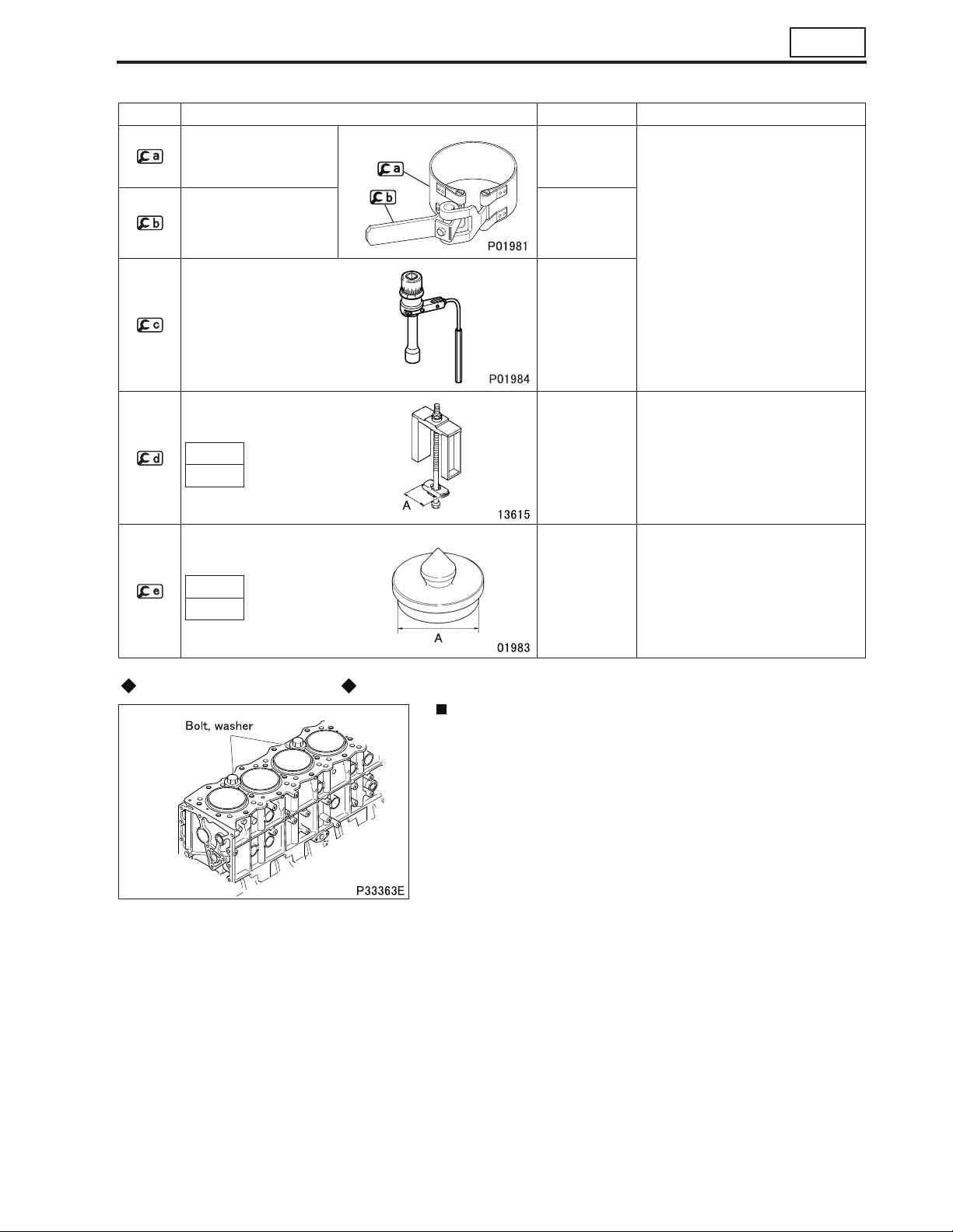
Mark Tool name and shape Part No. Application
Piston guide clamp MH061760
Piston guide lever MH061658
Installation of piston and connecting
rod
Socket wrench MH061560
Cylinder liner extractor
A
φ117.5
MH061761 Removal of cylinder liner
11
Cylinder liner installer
A
φ117.5
Inspection before removal
MH061771 Installation of cylinder liner
Retaining cylinder liners
• The cylinder liners may move up when the crankcase is turned
over, or the crankshaft is rotated after the pistons are installed.
To prevent this, retain the cylinder liners by holding their flanges
with bolts and washers.
11-41
Page 42
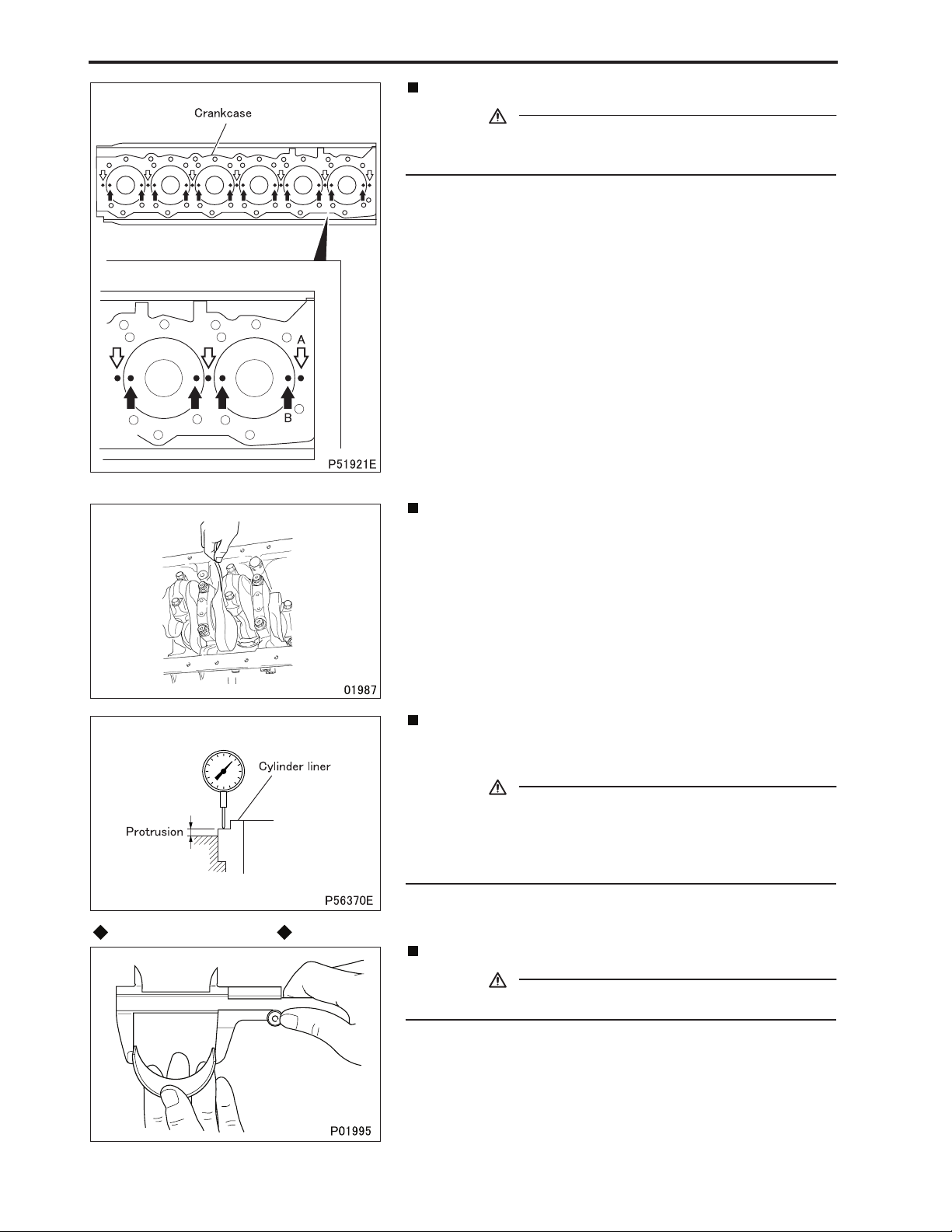
PISTON AND CONNECTING ROD, CYLINDER LINER
Inspection: Piston projection from crankcase top surface
CAUTION
• The amount of piston projection affects engine performance and must therefore be inspected without fail.
• Set the piston at the top dead center.
• Mark reference points A (seven points in total) on the top sur-
face of the crankcase as shown in the illustration. Using each of
the marks as a zero point, measure the amount of piston projection relative to the zero point (height of measurement point B –
height of reference point A).
• Make the measurements at the two measurement points B for
each cylinder (twelve points in total) using the reference point A
nearest to each measurement point, and calculate the average
value of all the measurements.
• If the average value is out of the standard value range, check
the clearances between all relevant parts.
Inspection procedure
Inspection: Connecting rod end play
• Measure the end play for every connecting rod.
• If any measurement exceeds the specified limit, replace the de-
fective part(s).
Inspection: Cylinder liner flange projection
• If the measurement deviates from the standard value, inspect
the installation and replace the defective part(s).
CAUTION
• If the cylinder liner flange protrusion is less than the specified value, the contact pressure of the cylinder head gasket
against the bore of the cylinder will not be high enough to
prevent gas leakage.
Inspection: Connecting rod bearing span when free
11-42
CAUTION
• Do not attempt to manually expand the bearings.
• If the span is less than the specified limit, replace both the upper
and lower bearings.
Page 43
11
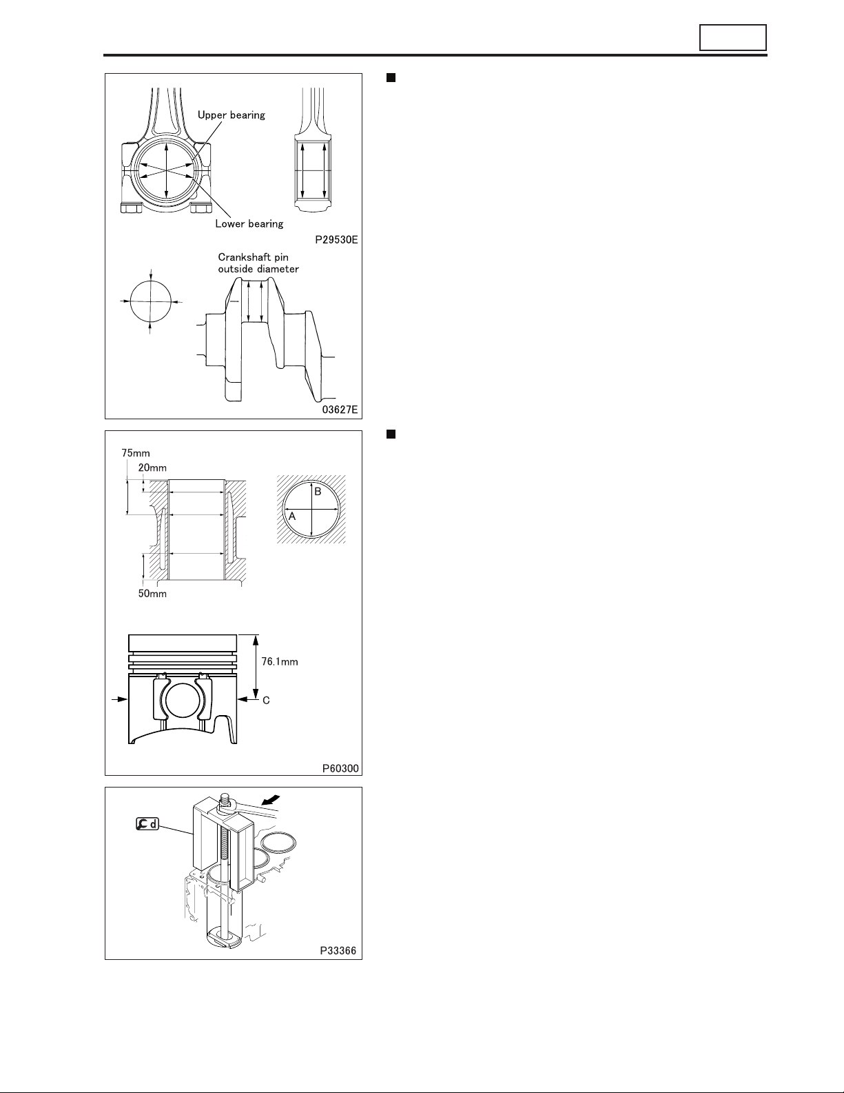
Inspection: Connecting rod bearing oil clearance
• Fit the lower bearing to the connecting rod cap and the upper
bearing to the connecting rod, then tighten the nut to a torque of
29 N
·m {3 kgf·m}.
• Measure the inside diameter of the bearing and the outside diameter of the crankshaft pin.
• If the clearance exceeds the limit, replace the defective part(s).
• If a bearing has to be replaced with an undersized one, machine
the crankshaft pin to the specified undersize diameter.
(See CRANKSHAFT AND CRANKCASE.)
Inspection: Clearance between piston and cylinder sleeve
• If the measurement deviates from the standard value, replace
the defective part(s).
A: Measuring point on the crankcase (in direction of the crank-
case axis).
B: Measuring point on the crankcase (vertical to the crankcase
axis).
C: Measuring point on the piston outer diameter (vertical to the
piston pin hole).
Replacement of cylinder liner
[Removal]
• If the cylinder liners will need to be reused for some reason or
other, make countermarks to ensure correct reassembly.
11-43
Page 44
PISTON AND CONNECTING ROD, CYLINDER LINER
[Installation]
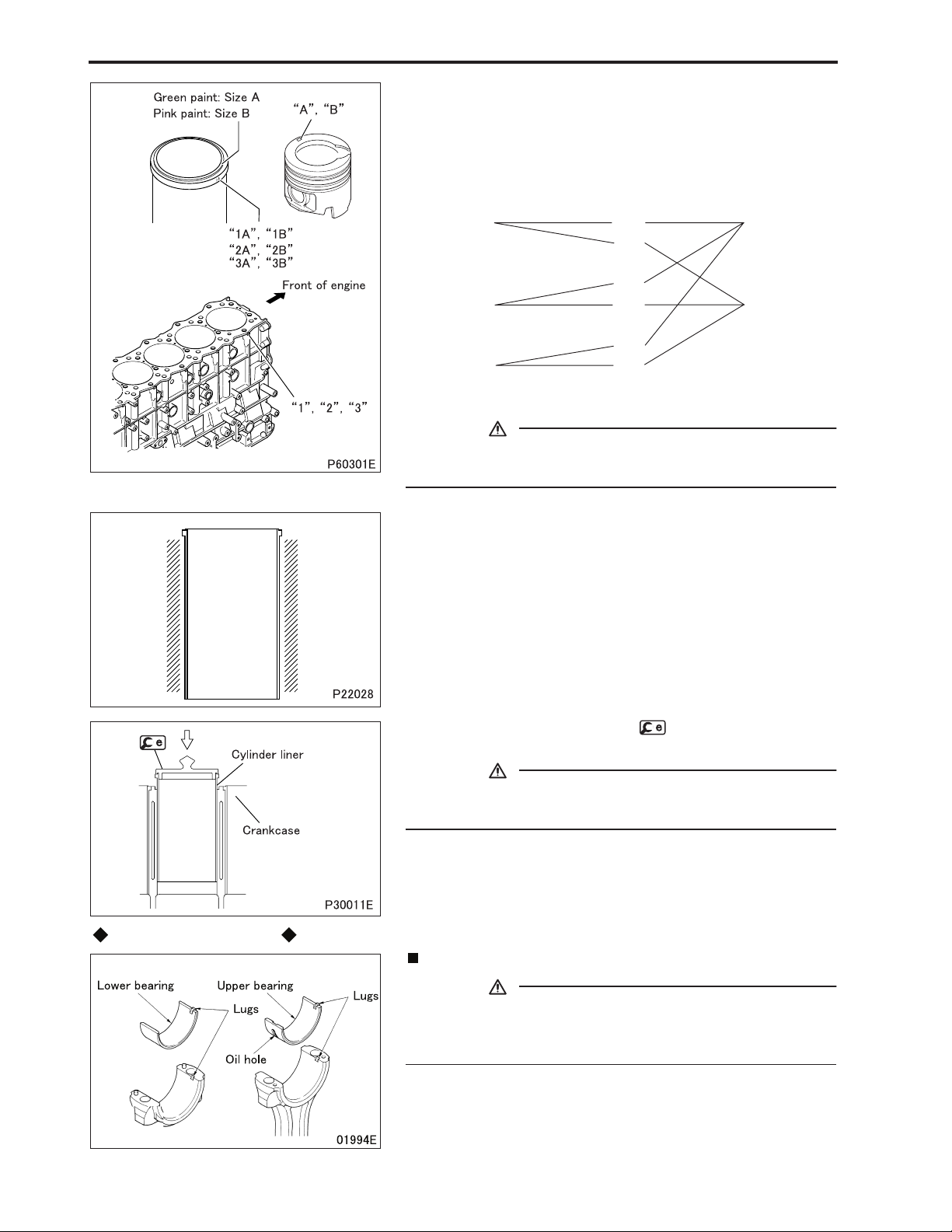
• The cylinder liner being installed must have the same size mark
as that on the crankcase as well as that on the piston.
Size mark
on crankcase
“1”
“2” “2B”
“3”
Size mark
on cylinder liner
“1B”
“2A”
“3A”
“3B”
Size mark
on piston
“A”“1A”
“B”
CAUTION
• Using a piston with the size mark different from the size
mark of the cylinder liner can lead to engine seizure.
• Apply a thin coat of engine oil onto the outside periphery
(hatched area) of the cylinder liner.
Installation procedure
• While pushing the top surface of evenly with hands, gently
insert the cylinder liner into the crankcase.
CAUTION
• Cylinder liners are thinly structured. Therefore, they must
be handled with extreme care.
Installation: Connecting rod bearings
CAUTION
• Do not reverse the positions of the lower bearing and the
upper bearing (with oil hole) when installing, as this may
cause seizure in the engine.
11-44
Page 45
11
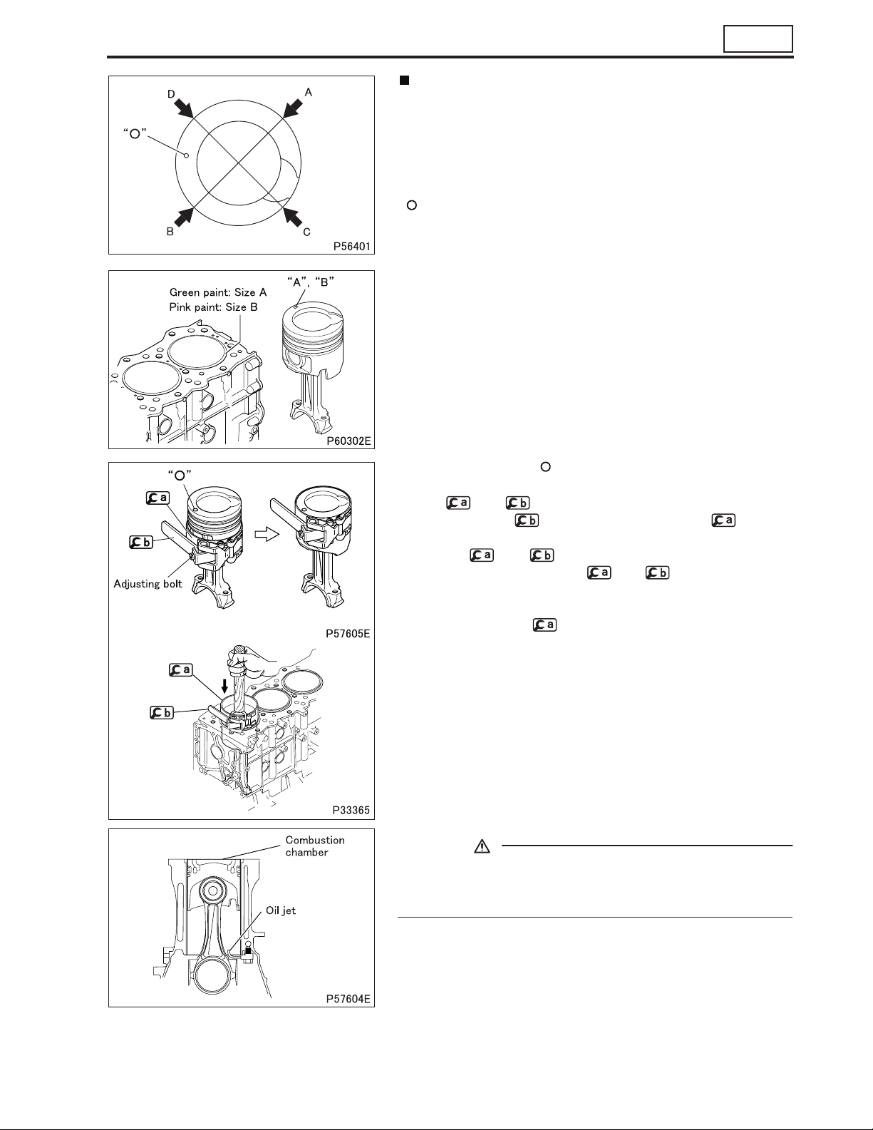
Installation: Piston and connecting rod
• Check that the piston ring end gaps are in their correct positions.
A: 1st compression ring gap
B: 2nd compression ring gap
C: Oil ring gap
D: Oil ring expander spring gap
“ ”: Front mark on piston
• Ensure that the size mark (“A”, “B”) on the piston is the same as
that on the cylinder liner.
• Face the front mark “ ” of the piston toward the front of the en-
gine.
• With and installed around the piston skirt, tighten the
adjusting bolt of until the inside diameter of matches
the outside diameter of the piston skirt.
• Remove and from the piston. Apply engine oil to the
following areas. Then, install and over the rings of the
piston.
• Outside surface of piston
• Inside surface of
• Cylinder liner inside surface
• Install the piston and connecting rod, taking care not to damage
the inside surface of the cylinder liner or the crank pin with the
connecting rod.
CAUTION
• Be careful not to scratch or damage head of the piston (a
part of the combustion chamber).
• Make sure that the connecting rod does not hit oil jet.
11-45
Page 46
PISTON AND CONNECTING ROD, CYLINDER LINER
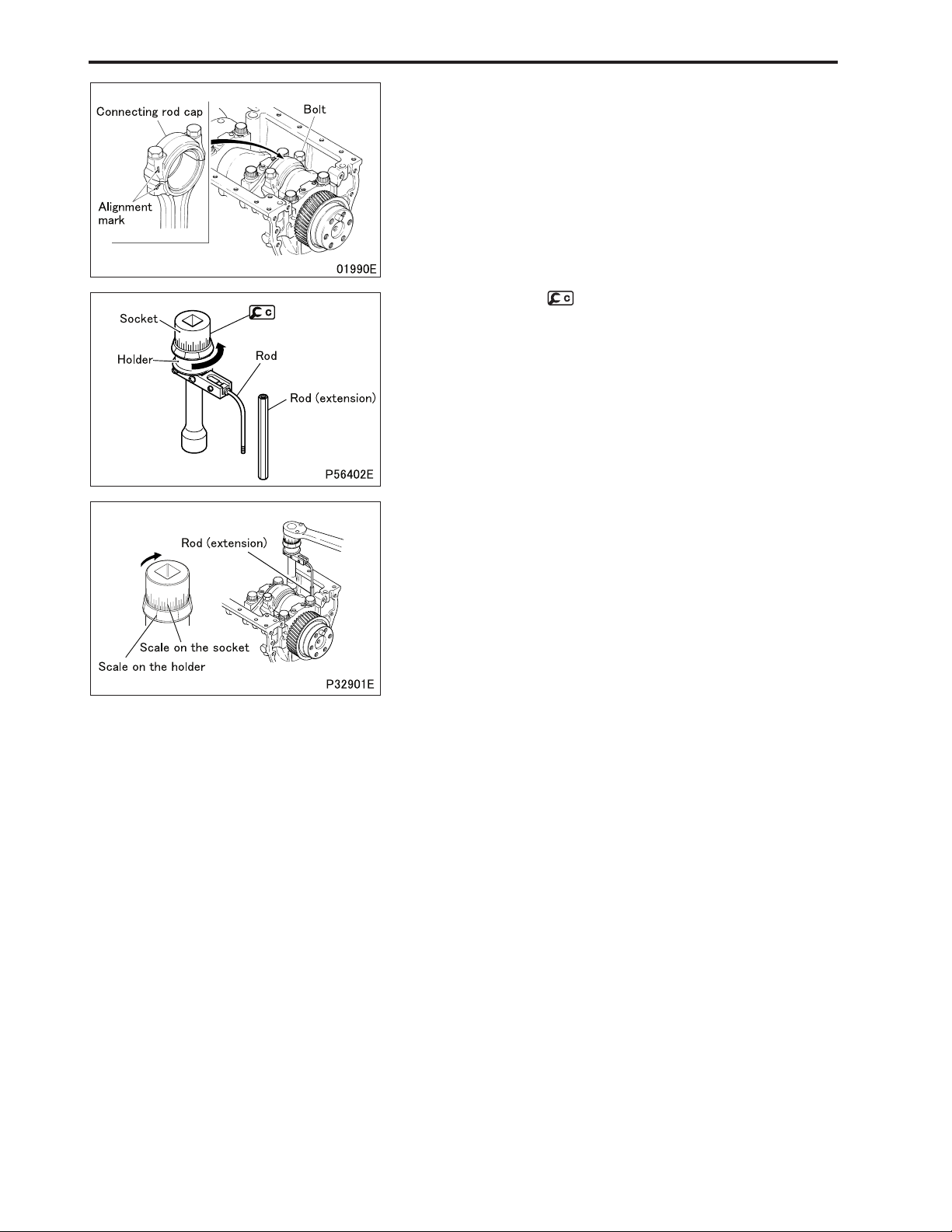
• After the piston and connecting rod have been installed, install
the connecting rod cap onto the connecting rod, ensuring that
the alignment marks are aligned. Tighten the bolts alternately as
follows.
• Tighten the bolts to a torque of 29 N
• Further tighten the bolts in the following sequence.
• Turn the holder of counterclockwise to preload the built-in
spring.
·m {3 kgf·m}.
• Set the tool such that the rod (extension) is pressed against the
crankshaft by the force of the spring.
• Align any line on the holder scale with any line on the socket
scale. (This will be used as the reference point = 0°.)
• From the reference point, turn the socket by 90° ± 5° in the di-
rection shown. Each division on the socket scale represents 5°.
• With the connecting rod cap installed, check the following items.
• Connecting rod end play
• Piston protrusion
11-46
Page 47

M E M O
11
11-47
Page 48
PISTON AND CONNECTING ROD, CYLINDER LINER
Piston and Connecting Rod
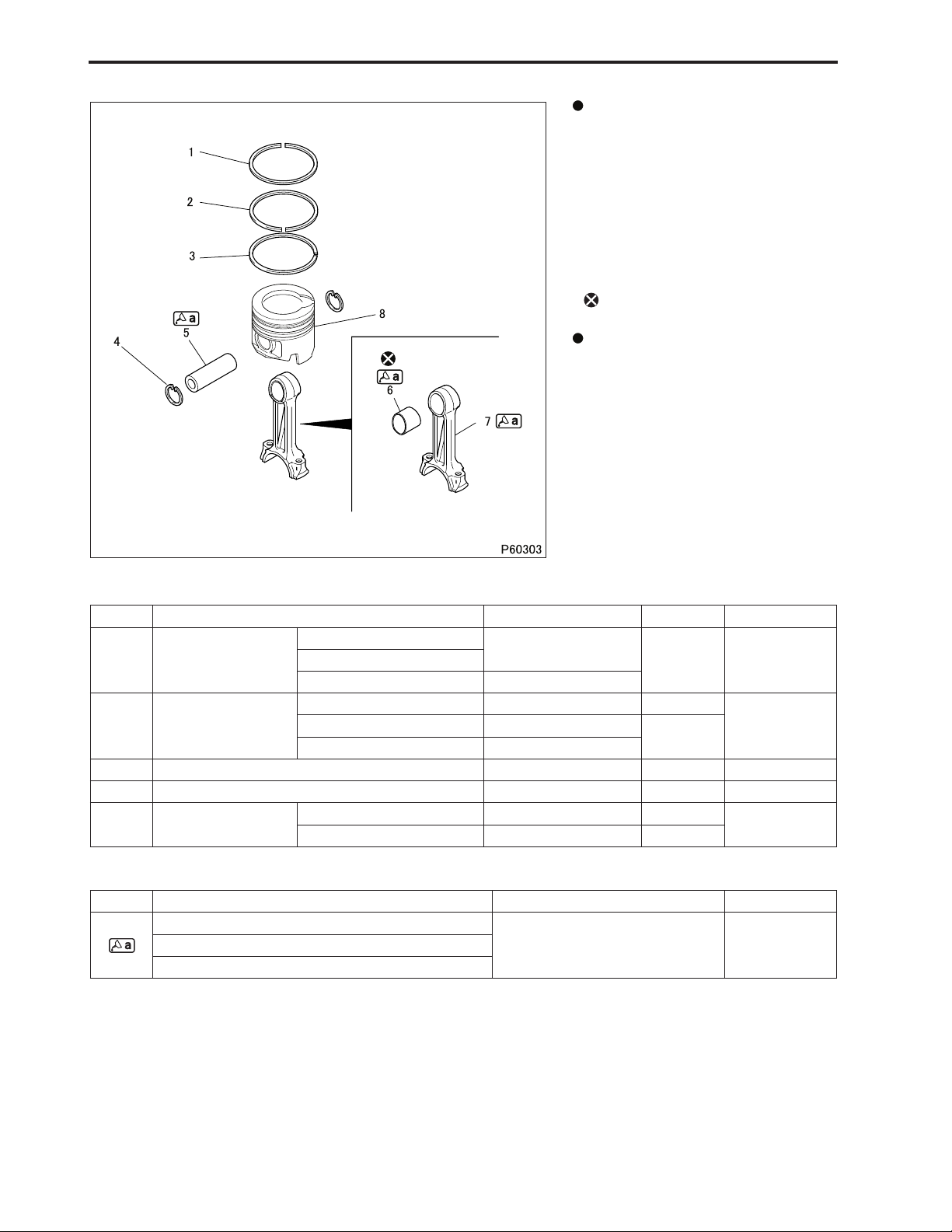
Disassembly sequence
1 1st compression ring
2 2nd compression ring
3 Oil ring
4 Snap ring
5 Piston pin
6 Connecting rod bushing
7 Connecting rod
8 Piston
: Non-reusable parts
Assembly sequence
Follow the disassembly sequence in reverse.
Service standards (Unit: mm)
Location Maintenance item Standard value Limit Remedy
1st compression ring
1 to 3 Piston ring end gap
Oil ring 0.3 to 0.55
1 to 3, 9
Piston ring side clearance in piston groove
5, 6 Piston pin-to-connecting rod bushing clearance 0.02 to 0.055 0.1 Replace
5, 8 Piston pin-to-piston clearance 0.004 to 0.022 0.05 Replace
7 Connecting rod
1st compression ring 0.13 to 0.18 0.2
Oil ring 0.025 to 0.065
Bend – 0.05
Twist – 0.1
0.45
+0.05
–0.10
1.5 Replace2nd compression ring
0.15
Replace2nd compression ring 0.065 to 0.105
Replace
Lubricant and/or sealant
Mark Points of application Specified lubricant and/or sealant Quantity
Piston pin outside surface
Engine oil As requiredConnecting rod bushing outside surface
Connecting rod bushing fitting surface of connecting rod
11-48
Page 49
Special tools
Mark Tool name and shape Part No. Application
11
Piston ring tool 30091-07100
Connecting rod bushing
puller kit
Removal procedure
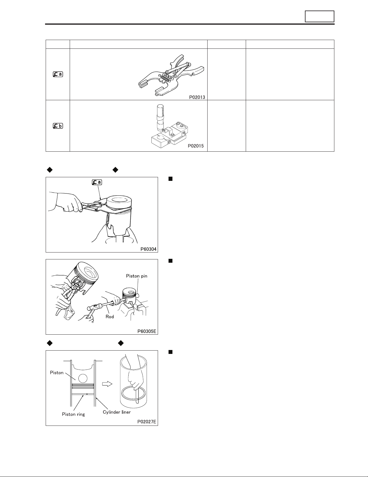
Removal: Piston ring
MH062556
Removal and installation of piston
rings
Removal and installation of connecting rod bushings
Inspection procedure
Removal: Piston pin
• Remove the piston pin by striking it with a rod and hammer.
• If the piston pin is difficult to remove, first heat the piston in hot
water or with a piston heater.
Inspection: Piston ring end gap
• Using the crown of a piston, push the piston ring horizontally into
a cylinder in the crankcase until it reaches the lower part of the
cylinder liner, where there is relatively small wear.
• Taking care not to move the piston ring, measure the end gap.
• If any of the rings has a gap exceeding the specified limit, re-
place all the piston rings as a set.
11-49
Page 50
PISTON AND CONNECTING ROD, CYLINDER LINER
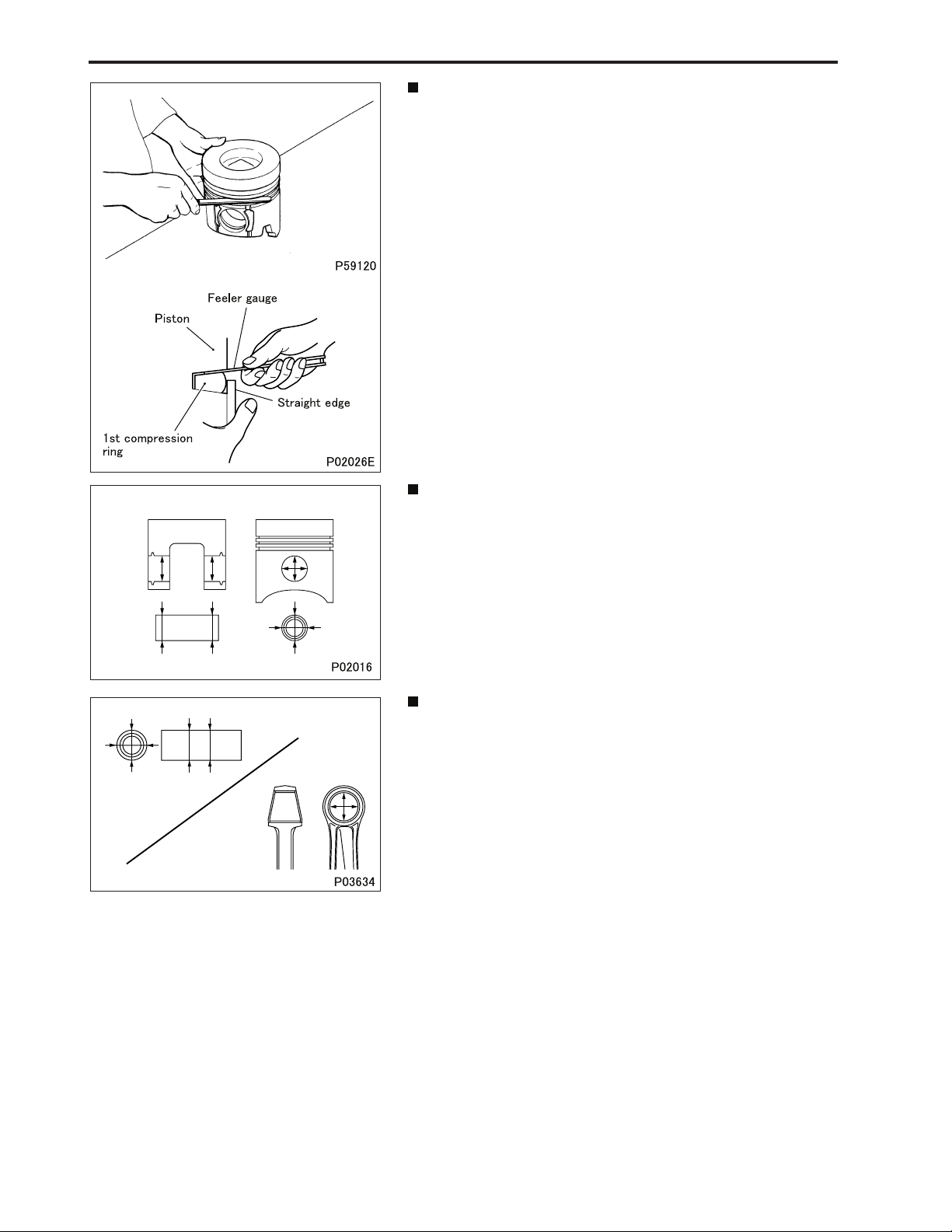
Inspection: Piston ring side clearance in piston groove
• Remove any carbon deposits from the ring groove in the piston.
• Measure the side clearance of each ring around the piston’s en-
tire periphery.
• If any of the measurements exceeds the specified limit, replace
the defective part(s). If any of the piston rings is defective, replace all the rings on the piston as a set.
• The side clearance of the 1st compression ring must be measured using a feeler gauge while holding the ring against the piston ring groove with a straight edge.
Inspection: Piston pin-to-piston clearance
• If the measurement exceeds the specified limit, replace the de-
fective part(s).
Inspection: Piston pin-to-connecting rod bushing clearance
• If any of the measurements exceeds the specified limit, replace
the bushing.
11-50
Page 51
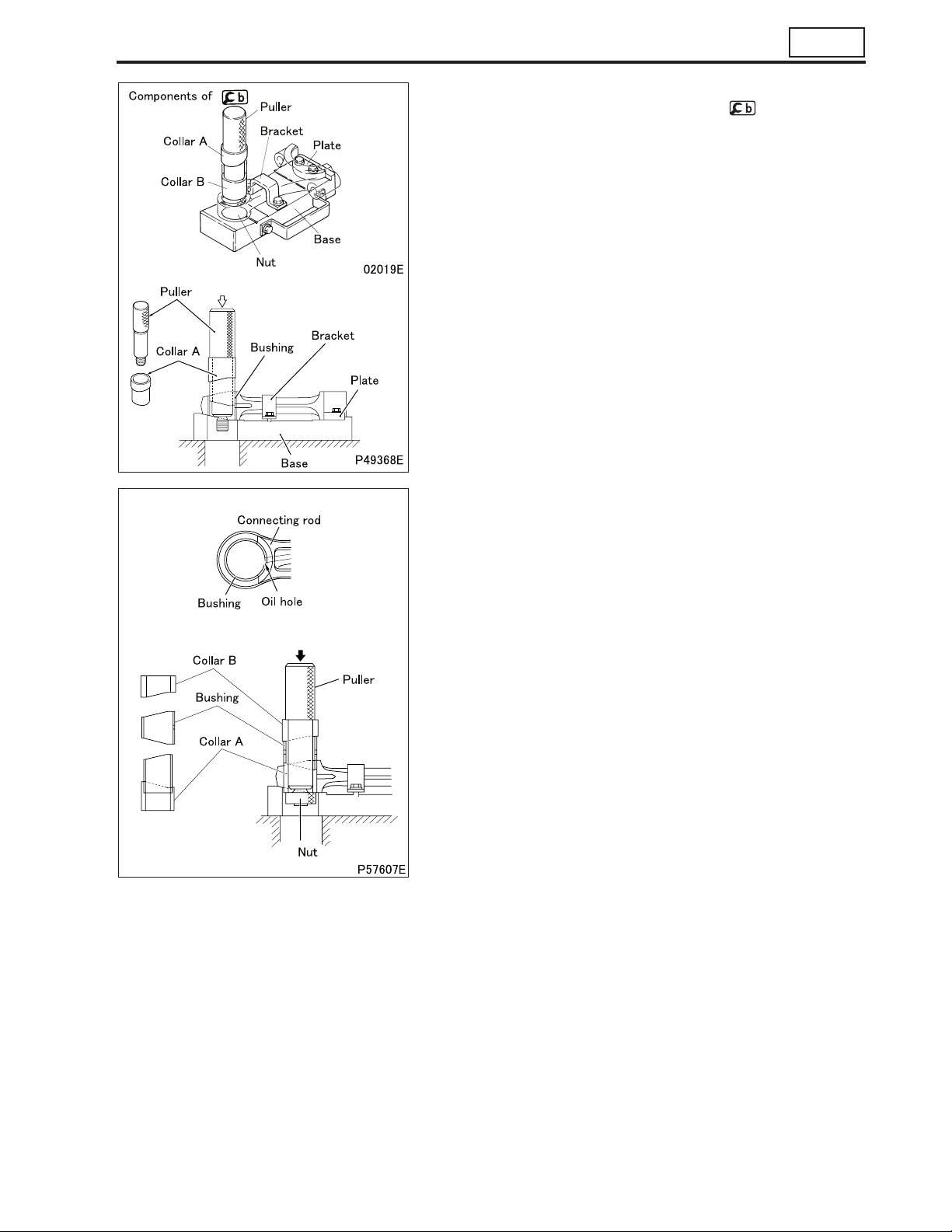
11
Replacement of connecting rod bushing
• Replace the connecting rod bushing using .
[Removal]
• Remove the upper bearing (if fitted) from the large end of the
connecting rod.
• Mount the connecting rod on the base and lock it in position with
the bracket and plate.
• Fit collar A over the puller with its ends facing in the illustrated directions. Then, slowly apply a pressure of approximately 49 kN
{5,000 kgf} to the puller with a press to force out the connecting
rod bushing.
[Installation]
• Apply engine oil to the outside surface of the connecting rod
bushing and the bushing fitting surface of the connecting rod.
• Fit collar B, the bushing, and collar A over the puller in the illustrated directions and lock this arrangement together with the nut.
• Align the oil holes in the connecting rod bushing and the connecting rod. Then, use a press to slowly apply a pressure of approximately 49 kN {5,000 kgf} to the puller until the bushing is
forced into place.
• After press-fitting the connecting rod bushing, measure the
clearance between the piston pin and connecting rod bushing.
• If the measurement is less than the standard clearance range,
ream the bushing.
11-51
Page 52
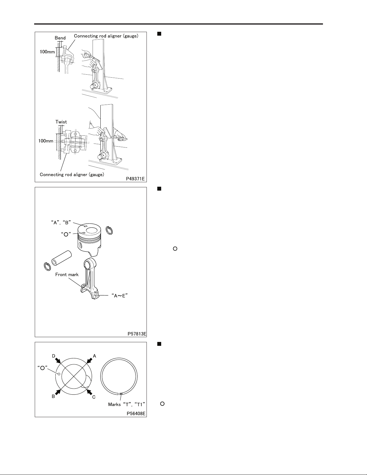
PISTON AND CONNECTING ROD, CYLINDER LINER
Inspection: Connecting rod bend and twist
• Mount the connecting rod on the connecting rod aligner. Also
mount the connecting rod bearings, piston pin, and connecting
rod cap to create the same conditions as are expected when the
connecting rod is mounted on a crankshaft. Tighten the nuts of
the connecting rod bearing cap to a torque of 29 N
• Measure the extent of bend and twist in the connecting rod.
• If either measurement exceeds the specified limit, replace the
connecting rod.
Installation: Piston and connecting rod
• If the piston and/or connecting rod have been replaced, assem-
ble them while paying attention to the following:
• The connecting rods on the same engine must all have the
same mass mark (A to E).
• Apply engine oil to the piston pin, and assemble the piston
and connecting rod with their marks facing in the illustrated directions.
“ ”: Front mark
• If the piston pin is difficult to insert, heat the piston in hot water
or with a piston heater.
·m {3 kgf·m}.
11-52
Installation: Piston rings
• With the manufacturer’s marks (found near the piston ring end
gaps) facing up, install the piston rings so that the end gap of
each ring is positioned as illustrated.
A: 1st compression ring end gap
B: 2nd compression ring end gap
C: Oil ring end gap
D: Oil ring’s expander spring end gap
“ ”: Front mark on piston
The manufacturer’s marks are present only on the 1st (“T”) and
2nd (“T1”) compression rings.
Page 53

M E M O
11
11-53
Page 54
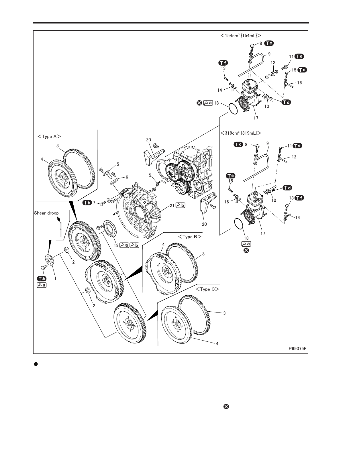
FLYWHEEL
Disassembly sequence
1 Washer plate
2 Pilot bearing
<Type A, Type B>
3 Ring gear
4 Flywheel
5 Engine speed sensor
6 Adapter <*a>
7 Plug
8 Eyebolt
11-54
9 Air outlet pipe
10 Air suction pipe
11 Eyebolt
12 Water inlet pipe
13 Eyebolt
14 Oil pipe
15 Eyebolt
16 Water outlet pipe
17 Air compressor (See Gr61.)
18 O-ring
19 Rear oil seal
20 Stiffener
21 Flywheel housing
: Non-reusable parts
*a: Varies depending on specifi-
cations
Page 55
Assembly sequence
Follow the disassembly sequence in reverse.
Service standards
Location Maintenance item Standard value Limit Remedy
Friction surface distortion 0.05 or less 0.2
Flywheel
4
<Type A, Type B>
Eccentricity of flywheel housing measured at spigot
21
joint section (when fitted)
Friction surface height
Friction surface runout
(when fitted)
Type A 21 20
Type B 44.5 43.5
– 0.2
– 0.2
Correct or
replace
Replace
Correct or
replace
Inspect or
replace
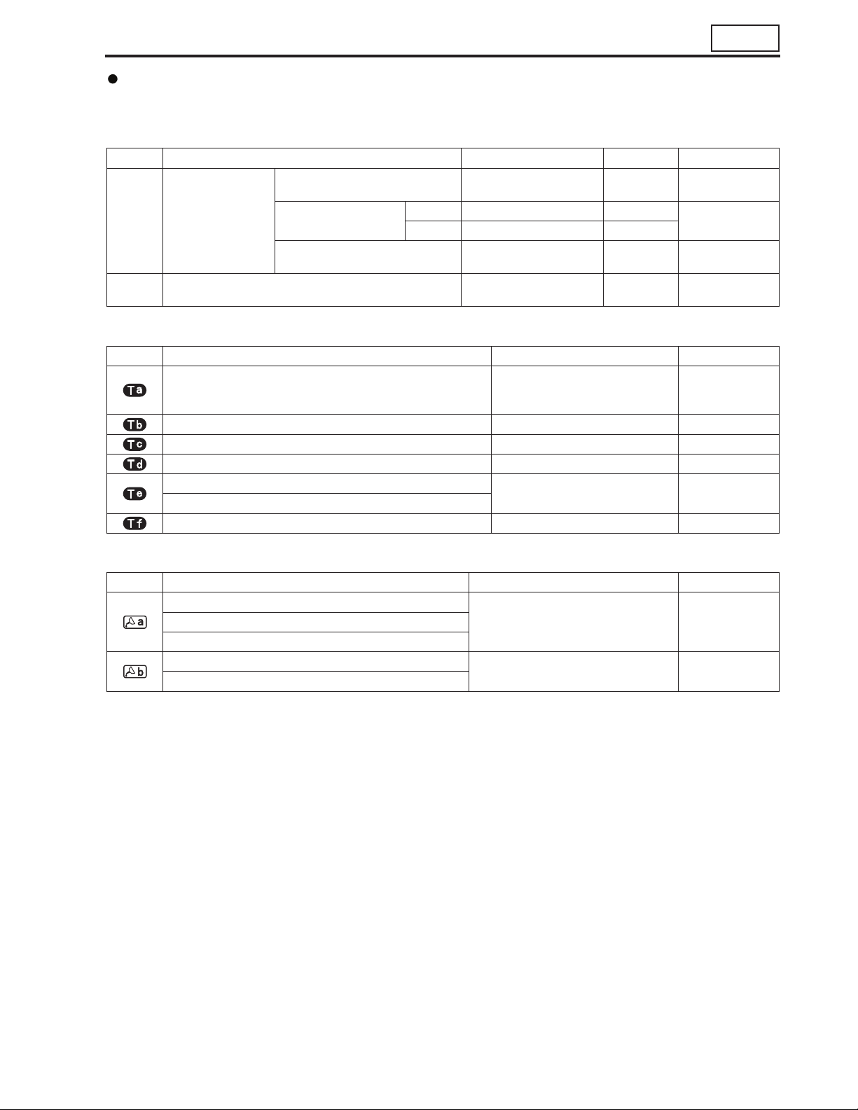
Tightening torque (Unit: N·m {kgf·m})
Mark Parts to be tightened Tightening torque Remarks
• Wet
• Can be reused
up to 3 times
Bolt (flywheel mounting) 98 {10} + 150°
Plug 88 {9} –
Eyebolt (air outlet pipe mounting) 98 {10} –
Bolt (air suction pipe mounting) 19 to 28 {1.9 to 2.8} –
Eyebolt (water inlet pipe mounting)
Eyebolt (water outlet pipe mounting)
Eyebolt (oil pipe mounting) 21 {2.1} –
50 {5.0} –
+10°
0
11
Lubricant and/or sealant
Mark Points of application Specified lubricant and/or sealant Quantity
Thread of bolts
Engine oil As requiredO-ring
Rear oil seal lip
Rear oil seal surface to be mated with flywheel housing
Engine mounting surface of flywheel housing
ThreeBond 1207C As required
11-55
Page 56
FLYWHEEL
Special tools
Mark Tool name and shape Part No. Application
Socket wrench MH062354
Installation of flywheel
Magnet base MH062356
Inspection before removal
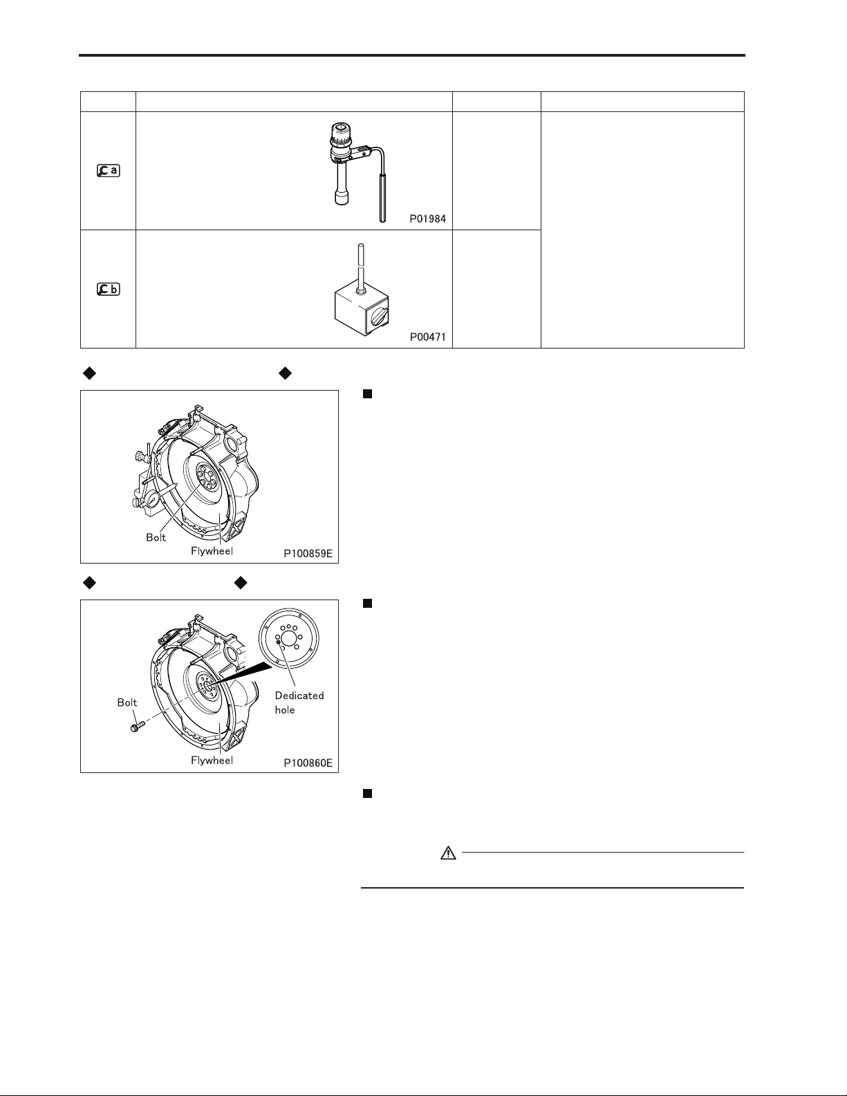
Inspection: Flywheel friction surface runout when fitted
• If the measurement exceeds the limit, check if the bolts are cor-
rectly tightened as well as the crankshaft mounting surface. Correct or replace the flywheel as required.
Removal procedure
Removal: Flywheel
• To remove the flywheel, use bolts (M16
mm) inserted into the dedicated holes in the flywheel.
Removal: Ring gear
• Heat the ring gear evenly with a gas burner or the like until it
reaches approximately 200°C, then remove it from the flywheel.
× 1.5 mm, Length 60
WARNING
• You may burn yourself if you touch the heated ring gear.
11-56
Page 57
Inspection procedure
11
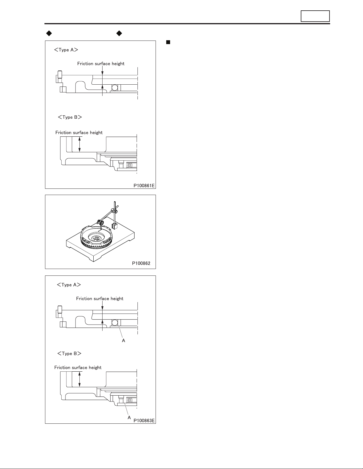
Inspection: Flywheel
(1) Friction surface height
• If the height is less than the limit, replace the flywheel.
(2) Friction surface distortion
• If the measurement exceeds the limit, rectify or replace the fly-
wheel.
• If the ring gear is evidently defective, replace the ring gear before inspecting the friction surface for distortion.
Rectification of friction surface
• Rectify the friction surface so that its height is not below the
specified limit, and it is parallel with surface A with an error not
exceeding 0.1 mm.
11-57
Page 58
FLYWHEEL
Installation procedure
Installation: Flywheel housing
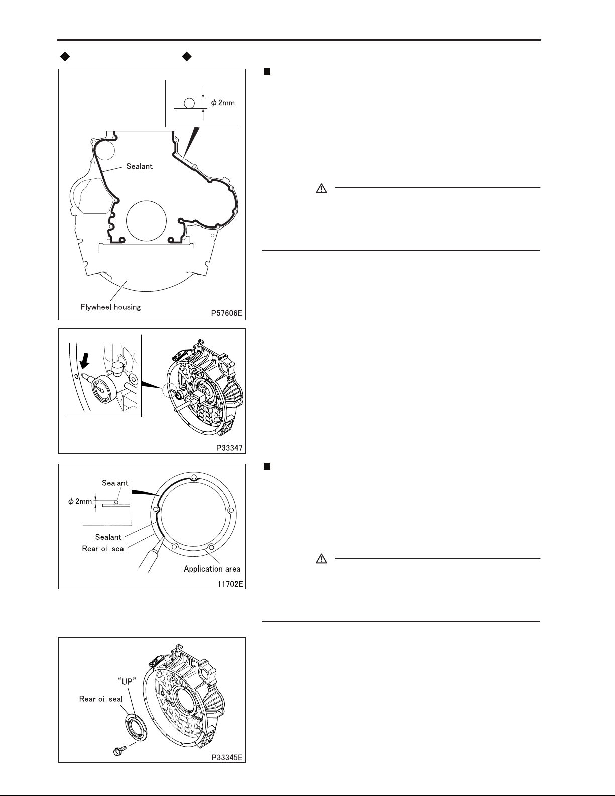
[Installation]
• Clean the flywheel housing surface where sealant is to be ap-
plied.
• Apply an even and continuous bead of sealant onto the flywheel
housing surface where the crankcase is to be mounted.
• Install the flywheel housing onto the crankcase within 3 minutes
following the application. Be careful not to smear the sealant
bead.
CAUTION
• Do not start the engine at least for an hour after the flywheel
housing has been installed.
• If the flywheel housing mounting bolts are subsequently
loosened, be sure to apply sealant again upon reassembly.
[Inspection]
• While turning the crankshaft, measure the flywheel housing for
any eccentricity at the location indicated in the illustration.
• If the eccentricity exceeds the limit, reassemble the flywheel.
• If the eccentricity still exceeds the limit after reassembly, replace
the defective part(s).
Installation: Rear oil seal
• Clean the rear oil seal surface where sealant is to be applied.
• Apply an even and continuous bead of sealant on the rear oil
seal as shown in the illustration.
• Install the rear oil seal onto the flywheel housing within 3 minutes following the application. Be careful not to smear the sealant bead.
CAUTION
• Do not start the engine at least for an hour after the rear oil
seal has been installed.
• If the rear oil seal mounting bolts are subsequently loosened, be sure to apply sealant again upon reassembly.
11-58
• Apply engine oil to the rear oil seal lip.
• Install the rear oil seal onto the flywheel housing ensuring that
the seal is faced in the illustrated direction.
Page 59
11
Installation: Air compressor
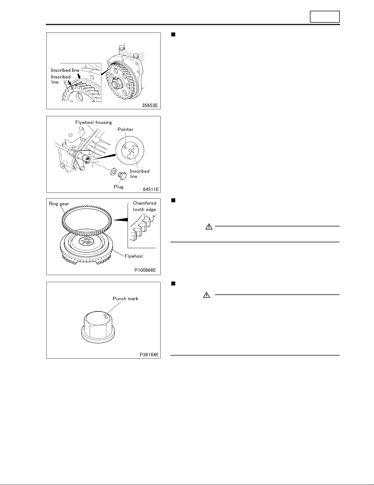
• Bring the No. 1 cylinder of the engine to top dead center of the
compression stroke.
• After aligning inscribed lines with each other, install the air compressor to the flywheel housing.
• Remove the inspection plug and check if the inscribed line is
aligned with the pointer.
• If not aligned, remove and refit the air compressor.
Installation: Ring gear
• Heat the ring gear evenly with a gas burner or the like until it
reaches approximately 200°C.
WARNING
• You may burn yourself if you touch the heated ring gear.
• Fit the ring gear with the side having non-chamfered tooth edges
toward the flywheel.
Installation: Flywheel
CAUTION
• Before installing a bolt, check the number of punch marks
on the bolt head. (Bolts with up to two punch marks can be
reused.)
The number of punch marks indicates the number of times
the bolt has been tightened in the past within the plastic region. If there are three punch marks (tightened three times
in the past), replace the bolt.
11-59
Page 60

FLYWHEEL
• Tighten the flywheel mounting bolts to a torque of 98 N·m {10
kgf·m}.
• Further tighten the bolts in the following procedure.
• Turn the holder of counterclockwise to preload the built-
in spring.
• Set such that the rod (extension) is pressed against
by the force of the spring.
• Align any line on the holder scale with any line on the socket
scale. (This will be used as the reference point = 0°.)
• From the reference point, turn the socket by 150° clock-
wise. Each division on the socket scale represents 5°.
• After tightening the bolt within the plastic region, make a
punch mark on the bolt head for subsequent identification.
+10°
0°
CAUTION
• The bolts should be tightened within the plastic region.
Never tighten them further than the specified angle.
11-60
Page 61

M E M O
11
11-61
Page 62
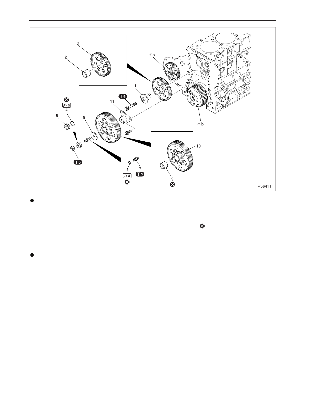
TIMING GEARS
Disassembly sequence
1 No. 1 idler shaft
2 No. 1 idler gear bushing
3 No.1 idler gear
4 O-ring
5 Collar
6 O-ring
Assembly sequence
Follow the disassembly sequence in reverse.
7 No. 2 idler bolt
8 Thrust plate
9 No. 2 idler gear bushing
10 No. 2 idler gear
11 No. 2 idler shaft
a: Air compressor gear
*
b: Crankshaft gear
*
: Non-reusable parts
11-62
Page 63
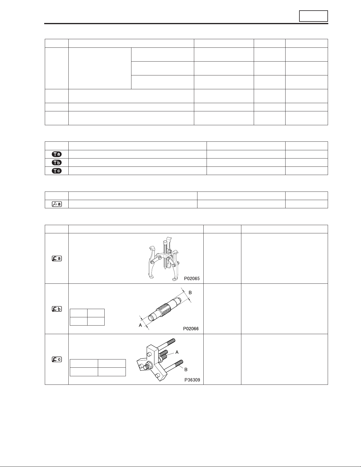
Service standards (Unit: mm)
Location Maintenance item Standard value Limit Remedy
No. 1 idler gear and air
compressor gear
– Backlash between gears
Clearance between No. 1 idler shaft and No. 1 idler
1, 2
gear bushing
3, 10 Idler gear end play 0.05 to 0.15 0.3 Replace
9, 11
Clearance between No. 2 idler gear bushing and No. 2
idler shaft
No. 1 idler gear and No. 2
idler gear
No. 1 idler gear and crankshaft gear
0.08 to 0.15 0.35 Replace
0.08 to 0.15 0.35 Replace
0.08 to 0.14 0.35 Replace
0.01 to 0.05 0.2 Replace
0.01 to 0.05 0.2 Replace
Tightening torque (Unit: N·m {kgf·m})
Mark Parts to be tightened Tightening torque Remarks
Bolt (No.1 idler gear mounting) 88 {9} –
Nut (collar mounting) 82 {8.4} –
No. 2 idler bolt 95 {9.7} –
Lubricant and/or sealant
Mark Points of application Specified lubricant and/or sealant Quantity
O-ring Engine oil As required
11
Special tools (Unit: mm)
Mark Tool name and shape Part No. Application
Gear puller MH061326 Removal of No. 1 idler shaft and gear
Idler gear push-puller
AB
φ 37 φ 40
No. 2 idler shaft puller
AB
× 1.25 M10 × 1.5
M12
MH062601
MH062562 Removal of No. 2 idler gear shaft
Removal and installation of No. 1 and
No. 2 idler gear bushings
11-63
Page 64
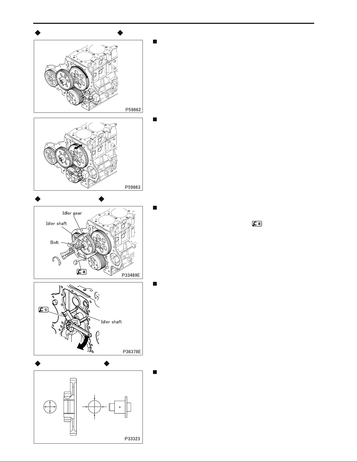
TIMING GEARS
Inspection before removal
Inspection: Backlash between gears
• For each pair of gears, measure the backlash at more than three
teeth.
• If any of the measurements exceeds the specified limit, replace
the defective part(s).
Inspection: Idler gear end play
• If the measurement exceeds the specified limit, replace the de-
fective part(s).
Removal procedure
Inspection procedure
Removal: No. 1 idler shaft and No. 1 idler gear
• With the bolt loosened by approximately 15 mm, pull out the No.
1 idler shaft from the crankcase using .
• Remove the bolt. Remove the No. 1 idler shaft and No. 1 idler
gear.
Removal: No. 2 idler shaft
Inspection: Clearance between No. 1 idler shaft and No. 1
idler gear bushing
[Inspection]
• If the measurement exceeds the limit, replace the bushing.
11-64
Page 65
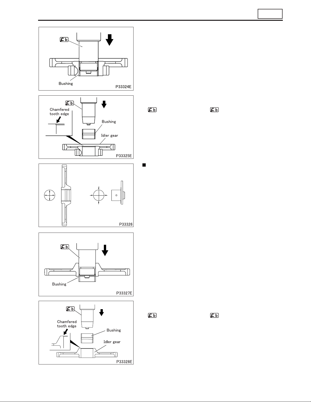
11
Replacement of No. 1 idler gear bushing
[Removal]
[Installation]
• Place the No. 1 idler gear as shown in the illustration. Using
, insert the bushing until contacts the chamfered tooth
edge of the gear.
• After installation, measure the clearance again.
• If the measurement is less than the standard value, ream the
bushing.
Inspection: Clearance between No. 2 idler gear bushing and
No. 2 idler shaft
[Inspection]
• If the measurement exceeds the limit, replace the bushing.
Replacement of No. 2 idler gear bushing
[Removal]
[Installation]
• Place the No. 2 idler gear as shown in the illustration. Using
, insert the bushing until contacts the chamfered tooth
edge of the gear.
• After installation, measure the clearance again.
• If the measurement is less than the standard value, ream the
bushing.
11-65
Page 66
TIMING GEARS
Installation: No. 2 idler shaft
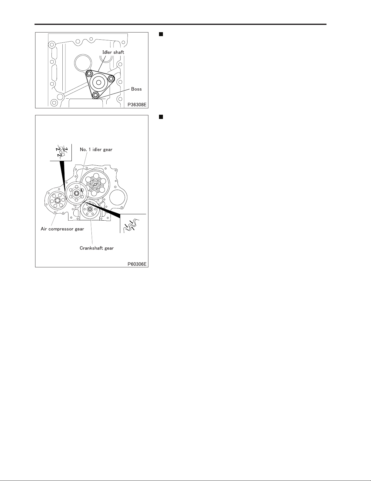
• Install the No. 2 idler shaft onto the crankcase ensuring that the
boss of the shaft faces down.
Installation: No. 1 idler gear
• Install the No. 1 idler gear such that the alignment mark “2” on
the gear is aligned with the alignment mark “2 2” on the air compressor gear.
• When installing the No. 1 idler gear, also ensure that the alignment mark “1 1” on the gear is aligned with the alignment mark
“1” on the crankshaft gear.
11-66
Page 67

M E M O
11
11-67
Page 68
CRANKSHAFT AND CRANKCASE
11-68
Page 69
11
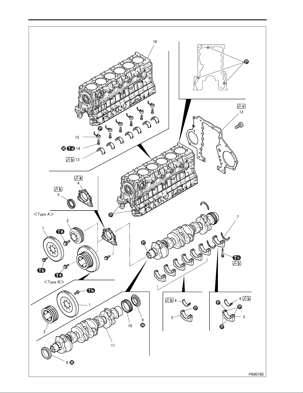
Disassembly sequence
1 Torsional damper
2 Crankshaft pulley
3 Front oil seal
4 Front cover
5 Main bearing cap
6 Lower main bearing
7 Thrust plate
CAUTION
• The check valve has been tightened using thread-locking compound and so, may deform during removal.
Once removed, the check valve must not be reused. Do not remove it unless defects are evident.
Assembly sequence
Follow the disassembly sequence in reverse.
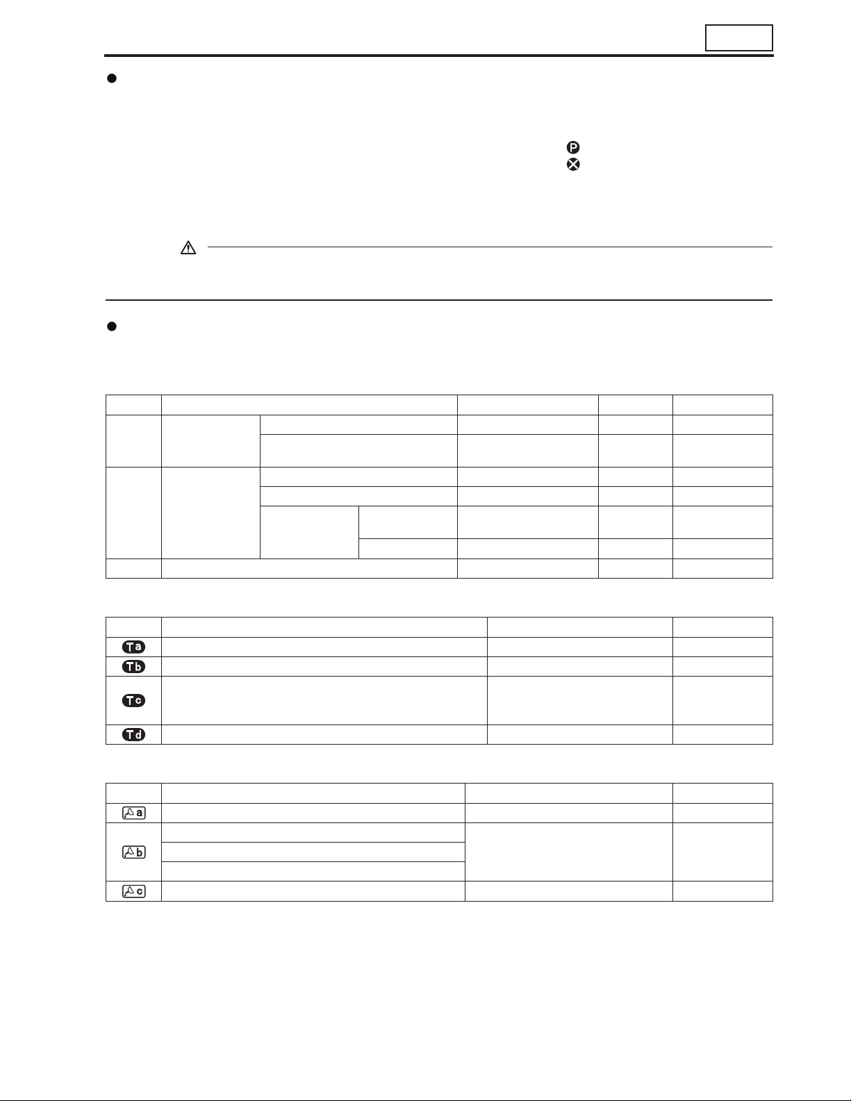
Service standards (Unit: mm)
Location Maintenance item Standard value Limit Remedy
Oil clearance 0.039 to 0.101 0.15 Replace
6, 13 Main bearing
11 Crankshaft
16 Distortion of crankcase top surface 0.07 or less 0.2 Replace
Span when free –
End play 0.10 to 0.25 0.4 Replace
Bend 0.025 or less 0.05 Rectify or replace
Pins and journals
8 Front oil seal slinger
9 Rear oil seal slinger
15 Oil jet
16 Crankcase
10 Crankshaft gear
11 Crankshaft
12 Rear plate
: Locating pin
: Non-reusable parts
13 Upper main bearing
14 Check valve
Less than
89.5
Out-of-roundness
Taper 0.006 or less – Rectify or replace
0.01 or less 0.03 Rectify or replace
Replace
Tightening torque (Unit: N·m {kgf·m})
Mark Parts to be tightened Tightening torque Remarks
Bolt (crankshaft pulley installation) 190 {19} –
Bolt (torsional damper installation) 78 {8} –
Bolt (main bearing cap installation) 78 + 90° {8 + 90° }
Check valve 34 {3.5} –
+10°
0
+10°
0
• Wet
• Reusable up
to 3 times
Lubricant and/or sealant
Mark Points of application Specified lubricant and/or sealant Quantity
Front cover surface to be mated with crankcase ThreeBond 1207C As required
Front oil seal lip
Engine oil As requiredThread of bolts
Inside surface of main bearing
Crankcase mounting surface of rear plate ThreeBond 1217H As required
11-69
Page 70
CRANKSHAFT AND CRANKCASE
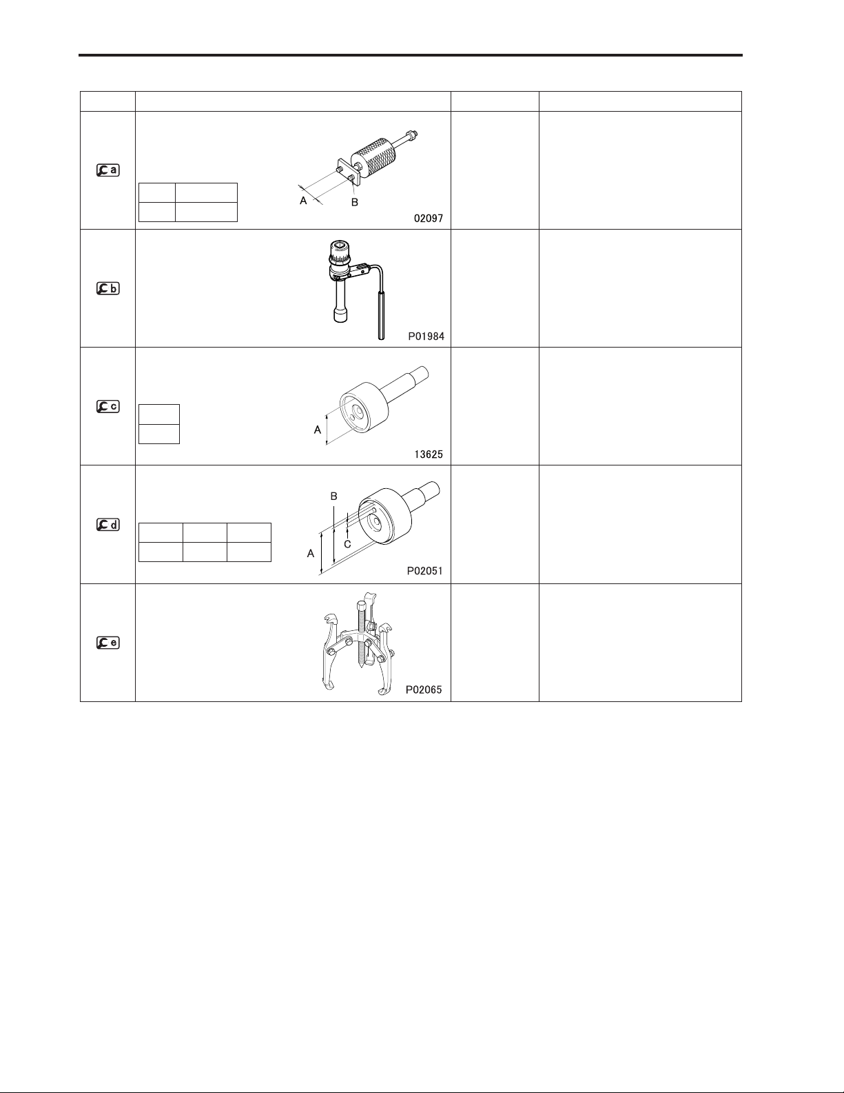
Special tools (Unit: mm)
Mark Tool name and shape Part No. Application
Main bearing cap extractor
AB
32 M8 × 1.25
Socket wrench MH061560 Installation of main bearing cap
Front oil seal slinger
installer
A
φ 76
Rear oil seal slinger installer
ABC
φ 104.5 φ 100 φ 14
MH061189 Removal of main bearing cap
MH062710 Installation of front oil seal slinger
MH061470 Installation of rear oil seal slinger
Gear puller MH061326 Removal of crankshaft gear
11-70
Page 71
Inspection before removal
Removal procedure
11
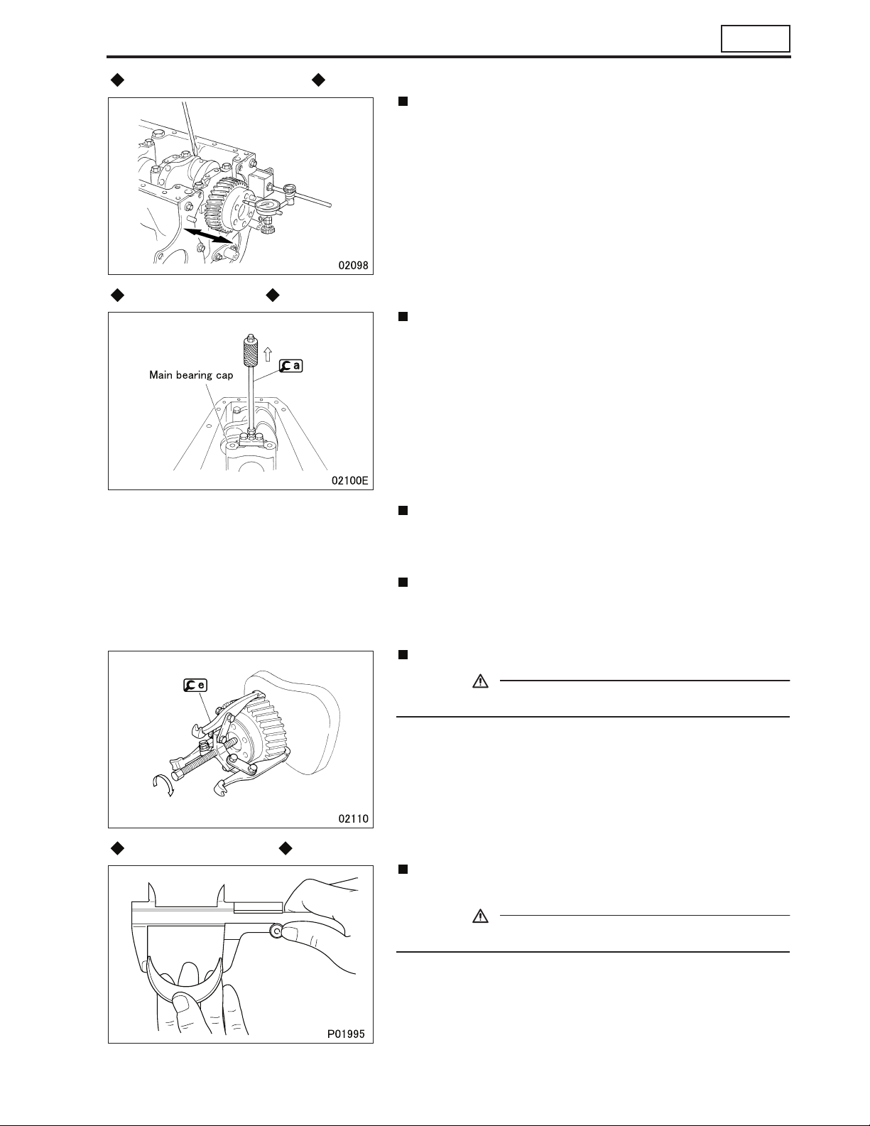
Inspection: Crankshaft end play
• If the measurement exceeds the specified limit, replace the
thrust plates with oversized ones.
Removal: Main bearing caps
Inspection procedure
Removal: Front oil seal slinger
• Taking care not to damage the crankshaft, split the rear oil seal
slinger using a chisel or a similar tool.
Removal: Rear oil seal slinger
• Taking care not to damage the crankshaft, split the rear oil seal
slinger using a chisel or a similar tool.
Removal: Crankshaft gear
CAUTION
• Do not tap off the crankshaft gear as this can damage it.
Inspection: Main bearing
(1) Main bearing span when free
CAUTION
• Do not attempt to manually expand the bearings.
• If the measurement exceeds the specified limit, replace the up-
per and lower bearings as a set.
11-71
Page 72
CRANKSHAFT AND CRANKCASE
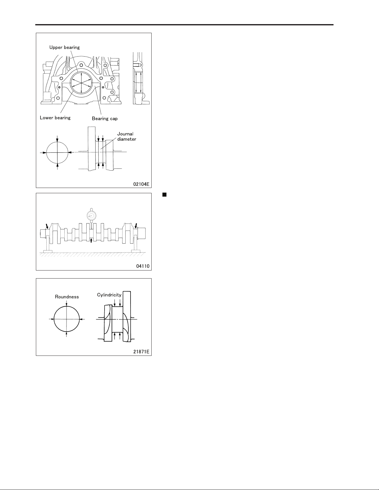
(2) Main bearing-to-crankshaft clearance (oil clearance)
• Fit the upper main bearing into the crankcase and the lower
main bearing into the main bearing cap.
• Tighten the main bearing cap bolts to a torque of 78 N·m {8
kgf·m}.
• Measure the inside diameter of the main bearing and the diameter of the corresponding crankshaft journal.
• If the difference between the measurements exceeds the specified limit, machine the crankshaft journal to one of the specified
undersize dimensions.
Inspection: Crankshaft
(1) Bend
• Measure the crankshaft at the center journal for bend while sup-
porting the shaft at the end journals.
• A half of the dial gauge reading obtained as the crankshaft is rotated by a full turn represents the bend of the crankshaft.
• If the measurement exceeds the specified limit, replace the
crankshaft.
(2) Roundness and cylindricity of crankshaft journals and
pins
• If any of the measurements exceeds the specified limits, grind
the crankshaft journal(s) and/or pin(s) to undersize(s) or replace
the crankshaft.
11-72
Page 73
11
2
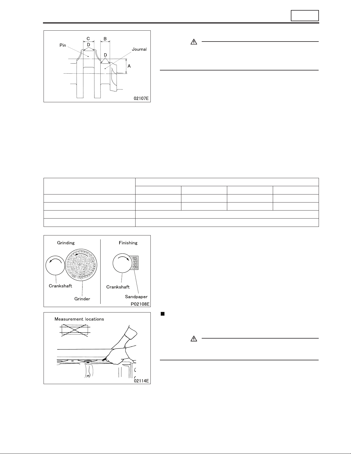
Grinding of crankshaft
CAUTION
• If the crankshaft pins and journals are ground to
undersizes, be sure to use bearings of corresponding
undersizes.
• Do not change the center-to-center distance A between the jour-
nal and pin.
A: 57.5 mm
• Do not change the journal width B and the pin width C.
B: 37 mm
C: 42 mm
• Finish the fillets D smoothly.
D: R4 ± 0.2 mm
• Carry out a magnetic inspection to check for cracks possibly
caused by grinding. Also, check that the hardness of the surface
has not dropped below Shore hardness number (Hs) 75.
• Replace the crankshaft if defects are evident.
Crankshaft undersize dimensions (Unit: mm)
0.25 0.50 0.75 1.00
Finished journal outside diameter 83.685 to 83.705 83.435 to 83.455 83.185 to 83.205 82.935 to 82.955
Finished pin outside diameter 69.67 to 69.69 69.42 to 69.44 69.17 to 69.19 68.92 to 68.94
Out-of-roundness 0.01 or less
Taper 0.006 or less
+0.2
0
+0.2
0
+0.025
–0.075
Undersizes
• When grinding, turn both the crankshaft and the grinder counterclockwise as viewed from the crankshaft front end.
• When finishing the crankshaft with whetstone or sandpaper, rotate the crankshaft clockwise.
Inspection: Distortion of crankcase top surface
• If the measurement exceeds the limit, correct the crankcase top
surface with a surface grinder.
CAUTION
• Do not grind the crankcase top surface so much as to compromise the correct piston projection.
11-73
Page 74
CRANKSHAFT AND CRANKCASE
Installation procedure
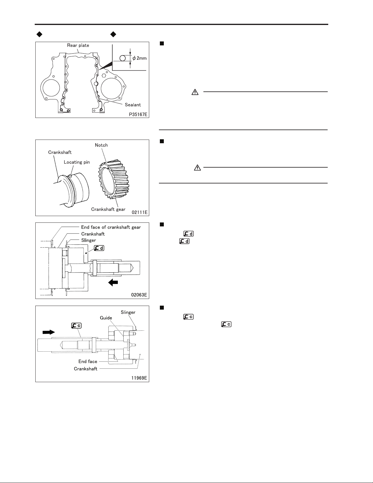
Installation: Rear plate
• Clean the rear plate surface where sealant is to be applied.
• Apply an even and continuous bead of sealant onto the rear
plate surface where the crankcase is to be mounted.
• Install the rear plate onto the crankcase within 3 minutes following the application. Be careful not to smear the sealant bead.
CAUTION
• Do not start the engine at least for an hour after the rear
plate has been installed.
• If the rear plate mounting bolts are subsequently loosened,
be sure to apply sealant again upon reassembly.
Installation: Crankshaft gear
• Heat the crankshaft gear to approximately 100°C with a burner
or the like.
WARNING
• Be careful not to get burned.
• Align the key fitted in the crankshaft with the slot in the crank-
shaft gear. Drive the gear into position by lightly striking its end
face with a plastic hammer.
Installation: Rear oil seal slinger
• Using , install the rear oil seal slinger onto the crankshaft
until comes into positive contact with the end face of the
crankshaft gear.
Installation: Front oil seal slinger
• Using , install the front oil seal slinger onto the crankshaft
until the end face of comes into positive contact with the
guide.
11-74
Page 75
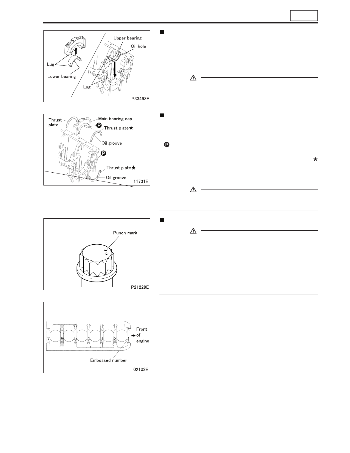
11
Installation: Main bearing
• Install the main bearings with their lugs aligned as shown in the
illustration. When the crankshaft journals have been ground to
an undersize, use undersized main bearings.
Available main bearing undersizes: 0.25 mm, 0.50 mm, 0.75
mm, 1.00 mm
CAUTION
• The upper main bearing has an oil hole. The lower main
bearing has no oil hole. Do not confuse the upper and lower
bearings, as this can cause seizure in the engine.
Installation: Thrust plate
• Install trust plates on both sides of the main bearing cap and the
rear end of the crankcase, ensuring that the oil grooves face outside.
: Locating pin
NOTE
• If oversized thrust plates are to be used, those with a
mark must be the same in size. Oversized thrust plates are
available in the following sizes: 2.6 mm, 2.75 mm and 2.9
mm.
CAUTION
• If thrust plates are installed with the oil grooves facing inside, the engine may seize.
Installation: Main bearing cap
CAUTION
• Before installing the main bearing cap bolts, check the
number of punch marks on the head of each bolt. (A bolt
with two or less marks is reusable.)
• The number of punch marks corresponds with the number
of times the main cap bolt has been tightened using the
torque-turn tightening method. Any bolt that has three
marks (i.e. that has been used three times) must be replaced.
• Starting at the front of the engine, fit the main bearing caps in
the order of the embossed numbers facing the illustrated direction.
11-75
Page 76
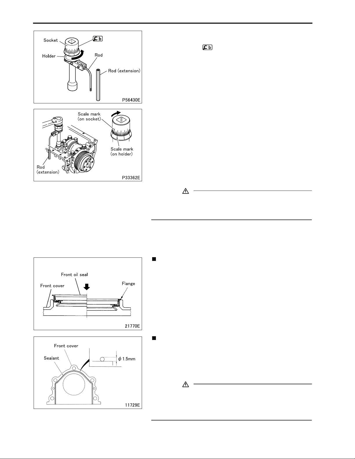
CRANKSHAFT AND CRANKCASE
• Tighten all the bolts to 78 N·m {8 kgf·m}, then additionally tighten
them according to the following procedure.
• Turn the holder of counterclockwise to pretension the inter-
nal spring.
• Set the tool such that the rod (extension) is pressed against the
crankshaft by the force of the spring.
• Align a scale mark on the socket with a scale mark on the holder. (This point will be the point of reference, or the 0° point.)
• Starting with this point of reference, turn the socket with a
wrench in the illustrated direction until the scale on the socket indicates 90°.
One graduation on the socket-side scale represents 5°.
• After tightening the bolts using the above torque-turn tightening
method, make a punch mark on the head of each bolt to indicate
the number of times that it has been used.
CAUTION
• The bolts that have been tightened using the torque-turn
method must never be additionally tightened after the final
angular tightening.
• After installing the main bearing cap, rotate the crankshaft by
hand. If it cannot be rotated smoothly, inspect the main bearing
caps for correct installation.
Installation: Front oil seal
• Install the front oil seal onto the front cover while pressing the
seal’s entire periphery evenly to prevent it from tilting.
• Install the front oil seal until its flange comes into positive contact
with the front cover.
Installation: Front cover
• Clean the front cover surface where sealant is to be applied.
• Apply an even and continuous bead of sealant onto the front
cover surface where the crankcase is to be mounted.
• Install the front cover onto the crankcase within 3 minutes following the application. Be careful not to smear the sealant bead.
CAUTION
• Do not start the engine at least for an hour after the front
cover has been installed.
• If the front cover mounting bolts are subsequently loosened, be sure to apply sealant again upon reassembly.
11-76
 Loading...