

Page 1
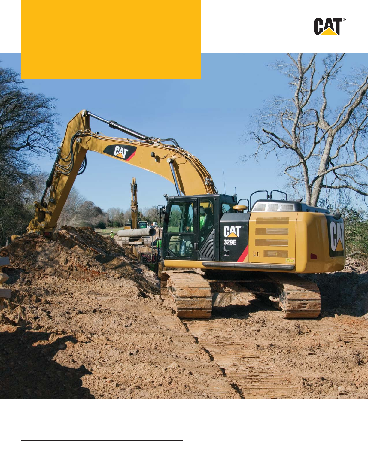
329E
Hydraulic Excavator
Engine Weight
Engine Model Cat
Net Power – SAE J1349/ISO 9249 173 kW 232 hp Maximum Operating Weight 31 279 kg 68,958 lb
Drive
Maximum Travel Speed 5.1 km/h 3.2 mph
Maximum Drawbar Pull 249 kN 55,977 lbf
®
C7.1 ACERT™ Minimum Operating Weight 29 057 kg 64,060 lb
Page 2
Introduction
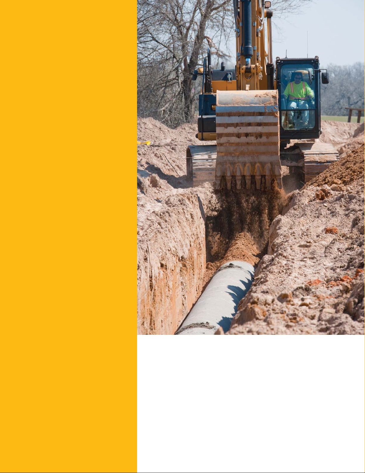
Since its introduction in the 1990s, the 300 Series
family of excavators has become the industry
standard in general, quarry, and heavy construction
applications. The all-new E Series and the 329E
will continue that trend-setting standard.
The 329E meets today’s U.S. emission standards.
It is also built with several new fuel-saving and
comfort-enabling features and bene ts that will
delight owners and operators.
If you are looking for more productivity and comfort,
less fuel consumption and emissions, and easier
and more sensible serviceability, you will nd
it in the all-new 329E and the E Series family
ofexcavators.
Contents
Engine ...................................................................3
Operator Station..................................................4
Hydraulics ............................................................5
Structures & Undercarriage .............................6
Front Linkage .......................................................7
Work Tools ............................................................8
Integrated Technologies ..................................10
Serviceability .....................................................11
Safety ..................................................................12
Complete Customer Care.................................13
Sustainability .....................................................14
Speci cations ....................................................15
Standard Equipment.........................................31
Optional Equipment...........................................32
2
Page 3
Engine
Reduced emissions, economical and reliable performance
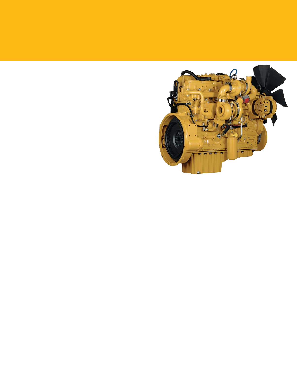
Cat® C7.1 ACERT™ Engine
The Cat C7.1 ACERT engine delivers more horsepower using
less fuel than the previous series engine.
Emissions Solution
The C7.1 ACERT engine is equipped to meet U.S.Tier4
Interim emission standards. Driven by customer input,
Caterpillar’s aftertreatment regeneration solution ensures
themachine works with no operator interventionneeded.
The machine comes with two modes of regeneration:
automatic and manual.
In automatic mode, the machine starts the regeneration
process once the ltering system reaches a certain level and
conditions are optimal. The system will not interrupt the
work process and can regenerate during machine operation.
Manual mode enables the operator to override the automatic
mode. With a touch of a button inside the cab, this mode
allows the operator to move the machine from ammableor
heat-restricted areas before initiating the regeneration process.
Biodiesel-Ready Fuel System
The C7.1 ACERT engine is equipped with an electroniccontrolled high-pressure fuel system that includes an electric
priming pump and three-layer fuel hose to allow the use
ofbiodiesel (meeting ASTM 6751 or EN 14214) up to B20
(biodiesel 20% mixture).
Cooling System
The cooling system features side-by-side-mounted hydraulic
oil cooler and engine radiator with a tilt-out condenser and
air-to-air aftercooler for easy cleaning. The fan automatically
adjusts to ambient temperatures to help reducefuel
consumption and noise.
Speed and Power Control
The E Series features speed control to maintain a constant
speed – regardless of load – to improve fuel economy.
Threedifferent power modes are offered: high power,
standard power, and economy power. The operator can
easily change between modes through the monitor or
consoleswitch to meet the needs for the job at hand –
alltohelp manage and conserve fuel.
3
Page 4
Operator Station
Comfort and convenience to keep people productive
Seats
The seat range includes air suspension, heated, and air cooled
options. Each option includes a reclining back, upper and lower
seat slide adjustments, and height and tilt angle adjustments
to meet operator needs for comfort and productivity.
Controls
The right and left joystick consoles can be adjusted to meet
individual preferences, improving operator comfort and
productivity during the course of a day. With the touch of the
button, one-touch idle reduces engine speed to help save fuel;
touch it again or move the joystick and the machine returns
to normal operating level. The heavy lift mode increases
machine system pressure to improve lift – a nice bene t in
certain situations. Heavy lift mode also reduces engine speed
and pump ow in order to improve controllability.
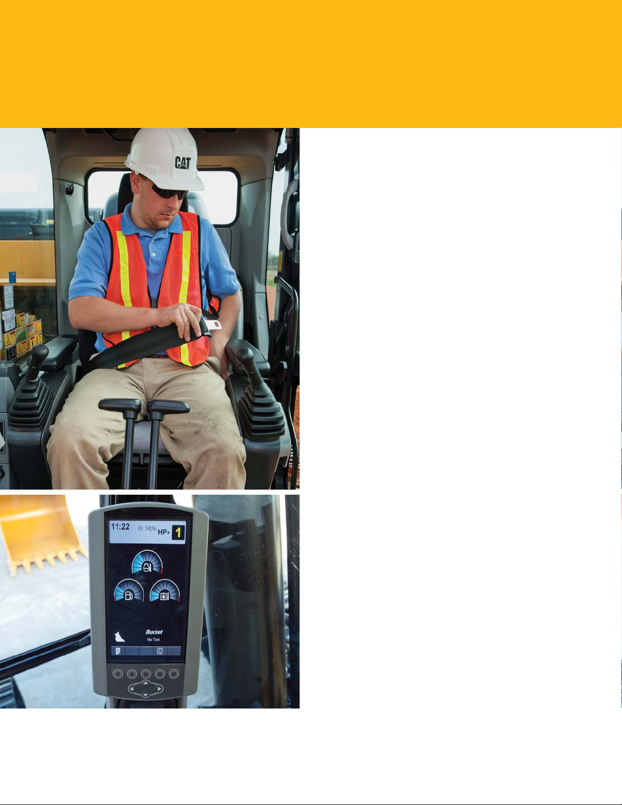
Monitor
The 329E is equipped with a new LCD (Liquid Crystal
Display) monitor that’s 40% bigger and has higher resolution
than the previous model’s monitor. In addition to an improved
keypad and added functionality, it’s programmable to provide
information in a choice of 42 languages to support today’s
diverse workforce.
An “Engine Shutdown Setting” accessible through the
monitor allows owners and operators to specify how long the
machine should idle before shutting down the engine, which
can save signicant amounts of fuel.
The image of the rearview camera is displayed directly on the
monitor. Up to two different camera images can be displayed
on the screen at the same time.
MP3-Ready Radio and Power Supply
The standard radio is equipped with a new auxiliary audio
port for MP3 players. Two 12-volt power supply sockets are
located near key storage areas for charging electronic devices.
Storage
Storage spaces are located in the front, rear, and side consoles.
Space near the auxiliary power supply holds MP3 players
and cell phones. The drink holder accommodates large mugs
with handles, and a shelf behind the seat stores large lunch
or toolboxes.
Automatic Climate Control
The climate control system features ve air outlets with
positive ltered ventilation, which makes working in the heat
and cold much more pleasant for operators.
4
Page 5
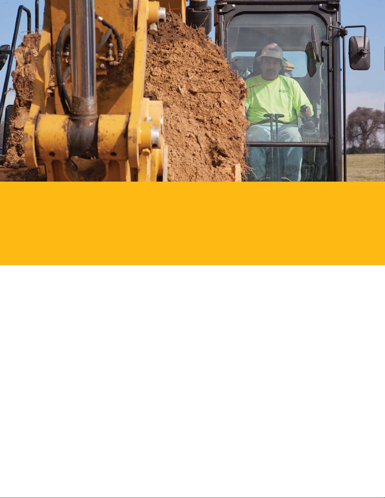
Hydraulics
Power to move more dirt, rock, and debris with speed and precision
Hydraulic Horsepower
Hydraulic horsepower is the actual machine power available to do work through implements and work tools. It’s much more
than just the engine power under the hood – it’s a core strength that differentiates Cat machines from other brands.
Main Control Valve and Auxiliary Valves
The 329E uses a high-pressure system to tackle the toughest of work in short order. The machine features a simple, highly
efcient back-to-back main control valve to improve fuel consumption and reliability. Also, shortened spool lengths and
abuilt-in drift reduction valve have been added for greater controllability.
Return Filter
The return lter is a capsule-type design with a cartridge inside. The Cat cartridge features a handle to help remove and change oil
without spillage or contamination. A sensor attached to the lter warns the operator if it is full or exceeds a certain pressure level.
Swing Priority Circuit
The swing priority circuit on the 329E uses an electric valve that’s operated by the machine’s Electronic Control Module
(ECM). Compared to using a hydraulic valve, an electric valve allows for more nely tuned control, which is critical during
material loading.
Electric Boom Regeneration Valve
An electric boom regeneration valve minimizes pump ow when the boom lowers down, which helps improve fuel ef ciency.
This unique Cat feature is optimized for any dial speed setting being used by the operator, which results in less pressure loss for
higher controllability and more productivity with lower operating costs.
Stick Regeneration Circuit
The 329E regenerates the ow of oil from the rod end to the head end of the stick cylinder during low-load, stick-in operation –
an approach that saves energy and expense.
5
Page 6
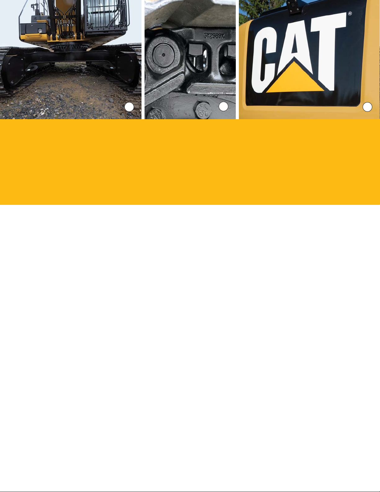
2
Structures & Undercarriage
Built to work in rugged environments
Frame
The upper frame (1) includes new reinforced mountings to support the RollOver Protective Structure (ROPS) cab; the lower frame is reinforced to increase
component durability.
Undercarriage
Fixed long undercarriage systems areavailable to support various work applications.
Heavy-duty track rollers, precision-forged carrier rollers (2), press-t pin master
joints, and enhanced track shoe bolts improve durability and reduce the risk of
machine downtimeand the need and cost toreplace components.
A segmented three-piece guiding guard is now offered to help maintain track
alignment and improve performance inmultiple applications.
A redesigned motor housing prevents mud packing anddebris buildup around seals.
31
Counterweights
Two counterweights (3) are available: 5.8 mt (6.3t) and 6.75 mt (7.4 t) options.
Thecounterweight removal system comes with new integrated links that enable easy
removal for maintenanceorshipping.
6
Page 7
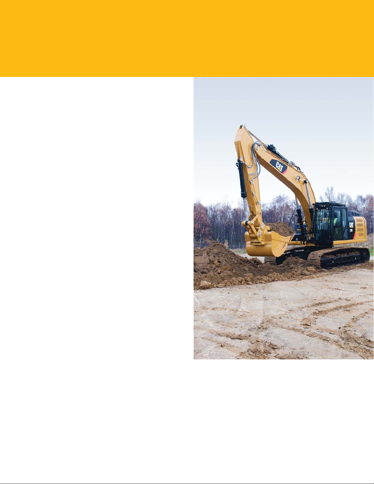
Front Linkage
Made for high stress and long service life
Booms and Sticks
The 329E is offered with a range of booms and sticks
(seelistbelow). Each is built with internal bafe plates for
added durability, and each undergoes ultrasound inspection
to ensure weld quality and reliability.
Large box-section structures with thick, multi-plate
fabrications, castings, and forgings are used in high-stress
areas such astheboom nose, boom foot, boom cylinder,
andstick foot to improve durability.
The boom nose pin retention method is a durable captured
ag design. Boom durability is improved with a number of
plate thickness changes. Also, the front linkage pins’ inner
bearing surfaces are welded, and a self-lubricated bearing
isused to extendservice intervals and increase uptime.
Selections
There are three basic boom options: HD, SLR, and ME.
Sticks match the boom descriptions and applications below:
HD = Heavy Duty
This type of boom is best used for reach applications where
conditions are optimal such as excavating basements, trenching
for utility lines, and sewer applications.
SLR = Super Long Reach
This conguration offers reaches to 60 feet. It is well suited
for ditch cleaning applications.
ME = Mass Excavation
Mass is best used for quarry, high-volume loading, and
other demanding applications. Mass fronts provide higher
digging forces due to the geometry of the boom and stick
relationship. Bucket linkage and cylinders are also built
forgreater durability.
7
Page 8
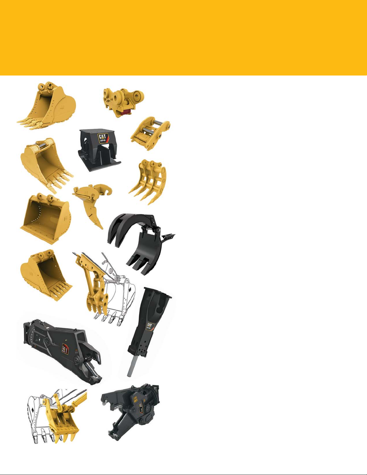
Work Tools
Dig, hammer, rip, and cut with condence
An extensive range of Cat Work Tools for the 329E includes
buckets, hydraulic hammers, multi-processors, scrap and
demolition shears, grapples, rippers, and thumbs. Each is
designed to optimize machine versatility and performance.
Couplers
Quick couplers allow one person to change work tools in
seconds for maximum performance and exibility on a job
site. One machine can move rapidly from task to task, and
a eet of similarly equipped machines can share a common
work tool inventory.
Cat Center-Lock™ Pin Grabber Coupler
Center-Lock is the pin grabber style of coupler and features
a patent-pending locking system. A highly visible secondary
lock clearly shows the operator when the coupler is engaged
or disengaged from the bucket or work tool.
Buckets
Cat Next Generation buckets are designed as an integral
part of the 329E system and feature new geometry for better
performance. The leading edge has been pushed forward,
resulting in more ef cient lling and better operator control
for greatly improved productivity. Wear coverage in the
corners and side cutter and sidebar protector coverage are
improved; a new lift eye design accepts a wide range of
shackle sizes. All benets are captured in a new bucket line
with a new bucket naming convention.
Four Durability Categories Suitable for Any Situation
Caterpillar offers four standard bucket categories for
excavators. Each category is based on intended bucket
durability when used in recommended applications and
material. Each bucket durability type is available as pin-on
or canbe used with a Quick Coupler. Red areas on bucket
images illustrate additional protection against wear as it
increases across each category.
8
Page 9
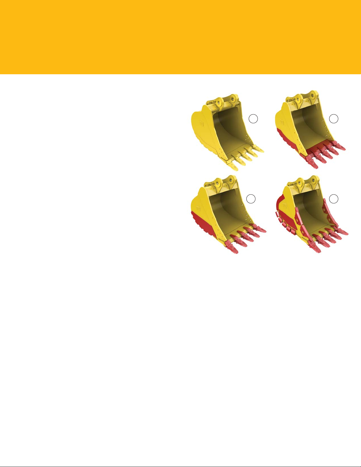
General Duty (GD)
GD buckets are for digging in low-impact, low-abrasion
material such as dirt, loam, and mixed compositions of dirt
and ne gravel.
Heavy Duty (HD)
The most popular bucket style, HD buckets are a good
starting point when digging conditions are not well known
like a wide range of impact and abrasion conditions that
include mixed dirt, clay, and rock.
Severe Duty (SD)
SD buckets are for higher abrasion conditions such as well
shot granite and caliche.
Extreme Duty (XD)
XD buckets are the new standard for high-abrasion
conditions, including high quartzite granite.
Specialty Buckets
In addition to the four levels of bucket durability categories,
several specialty buckets are available for the 329E, each with
a different purpose:
• Ditch cleaning for cleaning ditches, slope grading,
andother nish work
• Center-Lock Pin Grabber Performance for maximum
digging performance while keeping the versatility
andconvenience of a coupler
• Power for use in abrasive applications where breakout
force and cycle times are critical
• Wide tip for low-impact material where leaving a
smoother oor and minimal spillage are necessary
1 2
3 4
1) General Duty 2) Heavy Duty 3) Severe Duty 4) Extreme Duty
Hydraulic Kits
Caterpillar offers eld-installed hydraulic kits that
areuniquely designed to integrate Cat Work Tools with
Catexcavators. Hoses and tubes are pre-made, pre-shaped,
and pre-painted to make installation quick and easy.
Comprehensive Product Support
All Cat Work Tools are backed up by a world-wide network
of well-stocked parts depots and highly experienced service
and support personnel.
9
Page 10
1
Integrated Technologies
Solutions that make work easier and more efcient
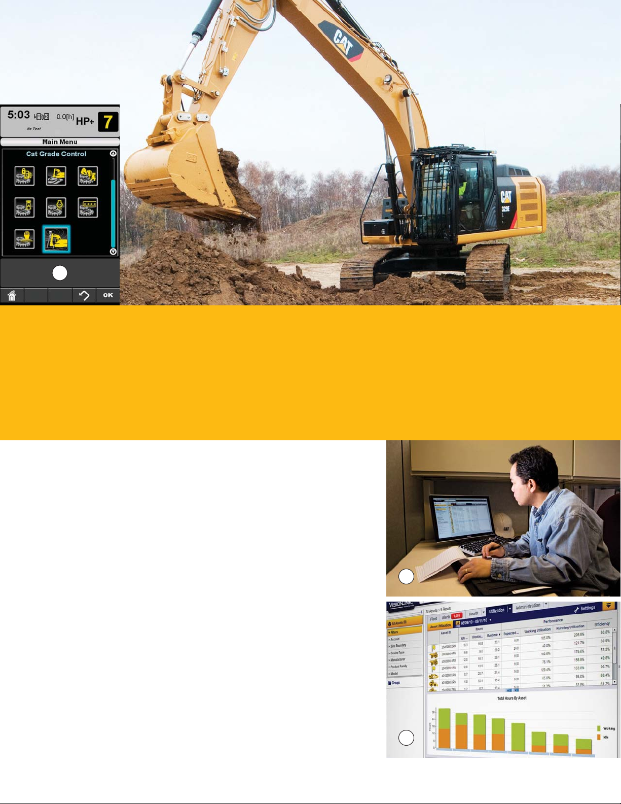
Cat® Grade Control Depth and Slope
This optional system combines traditional machine control and
guidance with standard factory-installed and calibrated components,
making the system ready to go to work the moment it leaves the factory.
The system utilizes internal front linkage sensors – well protected from
the harsh working environment – to give operators real-time bucket
tip position information through the cab monitor (1), which minimizes
the need and cost for traditional grade checking and improves job site
safety. It also helps the operator complete jobs in fewer cycles, which
means less fuel use. Cat dealers can upgrade the system to full threedimensional control by adding proven Cat AccuGrade™ positioning
technologies, including GPS and Universal Total Station (UTS).
Cat Product Link*
This deeply integrated machine monitoring system (2 and 3) is designed
to help customers improve their overall eet management effectiveness.
Eventsand diagnostic codes as well as hours, fuel consumption,idle
time, machine location, and other detailed information are transmitted
to a secure web based application called VisionLink™, which uses
powerful tools to communicate to users and dealers.
2
*Product Link licensing not available in all areas. Please consult your Cat dealer
foravailability.
10
3
Page 11
Serviceability
Fast, easy and safe access built in
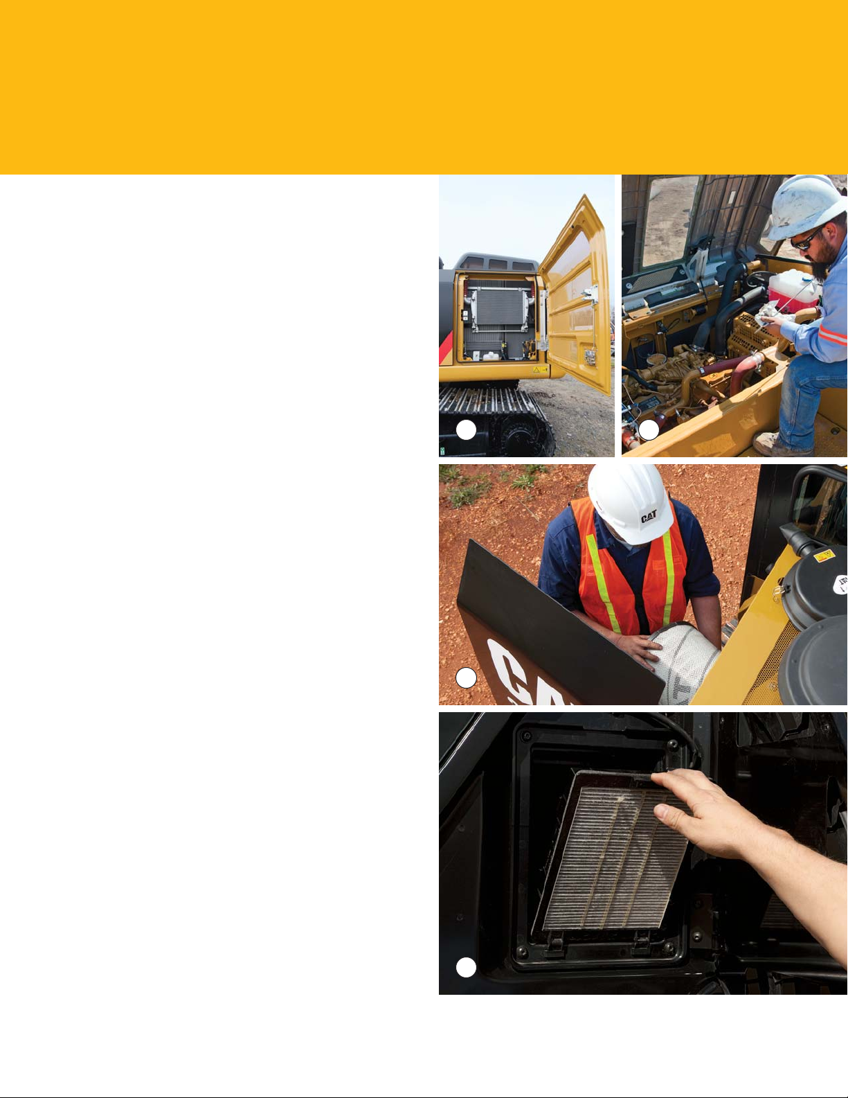
Service Doors
Wide service doors (1) and a new hood design (2) provideeasy
access to the engine and cooling compartments. Bothdoors
and hood feature enhanced hardware and a new screen
design to help minimize debris entry.
Compartments
The radiator, pump, and air cleaner (3) compartments provide
easy access to major components. The fresh air lter (4) is
located on the side of the cab to make it easier to reach and
replace as needed.
Other Service Improvements
The water separator with water level sensor has a primary
fuel lter element located in the pump compartment near
ground level; the electric priming pump is mounted on the
primary lter base and is easier to service than traditional
hand-priming pumps.
The fuel tank features a remote drain cock located in the
pump compartment to make it easy to remove water and
sediment during maintenance.
The engine oil check gauge and oil lter are situated in front
of the engine compartment for easy access, and a uniquely
designed drain cock helps prevent spills.
An optional QuickEvac™ system makes changing engine and
hydraulic oil easy to complete in minutes rather than hours.
1 2
3
4
11
Page 12
Safety
Features to help protect people
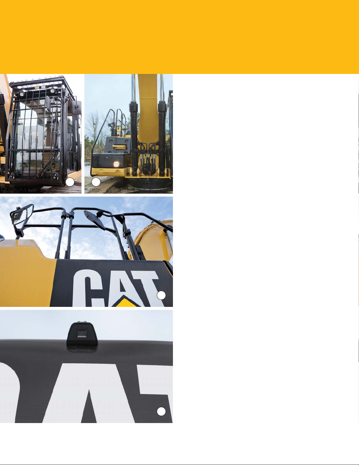
ROPS Cab
The ROPS-certied cab (1) allows a Falling Object Guard
Structure (FOGS) to be bolted directly to it to help protect
operators.
Sound Proong
Improved sealing and roof lining lower noise levels inside
thecab signicantly during machine operation.
Anti-Skid Plates
The surface of the upper structure and the top of the storage
box area are covered with anti-skid plates to help prevent service
personnel and operators from slipping during maintenance.
21
Steps, Hand and Guard Rails
Steps on the track frame and storage box (2) along with
extended hand and guard rails (3) to the upper deck enable
operators to more securely work on the machine.
Time Delay Cab and Boom Lights
For a predetermined amount of time after the engine start
key has been turned to the “OFF” position, lights will be
illuminated to enhance visibility. The time delay can vary
from0 to 90 seconds, which can be set through the monitor.
High Intensity Discharge (HID) Lights
Cab lights operate on a time delay for enhanced safety; lights
can be upgraded to HID for greater night time visibility.
Visibility – Windows
3
Increased glass coverage enhances visibility while meeting
thelatest ROPS regulations.
The 70/30 split conguration features an upper window
equipped with handles on the top and both sides so the
operator can easily slide it to store in the ceiling. The lower
window is removable and can be stored on the left wall of
thecab shell.
The large skylight provides enhanced overhead visibility,
excellent natural lighting, and good ventilation. The skylight
can be opened completely to become an emergency exit.
12
Monitor Warning System
The monitor is equipped with a buzzer that can warn operators
of critical events like “Engine Oil Pressure Decrease,” “Coolant
Temperature High,” or “Hydraulic Oil Temperature High” so
they can take any necessary action.
4
Rearview Camera
An optional rearview camera (4) housed in the counterweight
area is available as an attachment. The image projects through
the cab monitor to give the operator a clear picture of what’s
behind the machine.
Page 13
Complete Customer Care
Service you can count on
Product Support
Cat dealers utilize a worldwide parts network to maximize your machines’ uptime. Plus they can help
you save money with Cat remanufactured components.
Machine Selection
What are the job requirements and machine attachments? What production is needed? Your Cat dealer
can provide recommendations to help you make the right machine choices.
Purchase
Consider nancing options and day-to-day operating costs. Look at dealer services that can be included
in the machine’s cost to yield lower owning and operating costs over time.
Customer Support Agreements
Cat dealers offer a variety of customer support agreements and work with you to develop a plan to meet
your specic needs. These plans can cover the entire machine, including attachments, to help protect
your investment.
Operation
Improving operating techniques can boost your prots. Your Cat dealer has videos, literature, and other
ideas to help you increase productivity. Caterpillar also offers simulators and certied operator training
to help maximize the return on your investment.
Replacement
Repair, rebuild, or replace? Your Cat dealer can help you evaluate the cost involved so you can make the
best choice for your business.
13
Page 14
Sustainability
Generations ahead in every way
• The C7.1 ACERT engine, along with the Cat Clean Emissions Module (CEM), meets U.S. Tier 4
Interim emission standards.
• The 329E performs the same amount of work while burning 3% less fuel than the previous D Series
model, which means more efciency, less resources consumed, and fewer CO2 emissions.
• The 329E has the exibility of running on either ultra-low-sulfur diesel (ULSD) fuel with 15 ppm
of sulfur or less or biodiesel (B20) fuel blended with ULSD.
• A ground-level overll indicator rises when the tank is full to help the operator avoid spilling.
• The QuickEvac™ option ensures fast, easy, and secure changing of engine and hydraulic oil.
• The 329E is built to be rebuilt with major structures and components capable of being remanufactured
to reduce waste and replacement costs.
• An eco-friendly engine oil lter eliminates the need for painted metal cans and aluminum top plates.
The cartridge-style spin-on housing enables the internal lter to be separated and replaced; the used
internal element can be incinerated to help reduce waste.
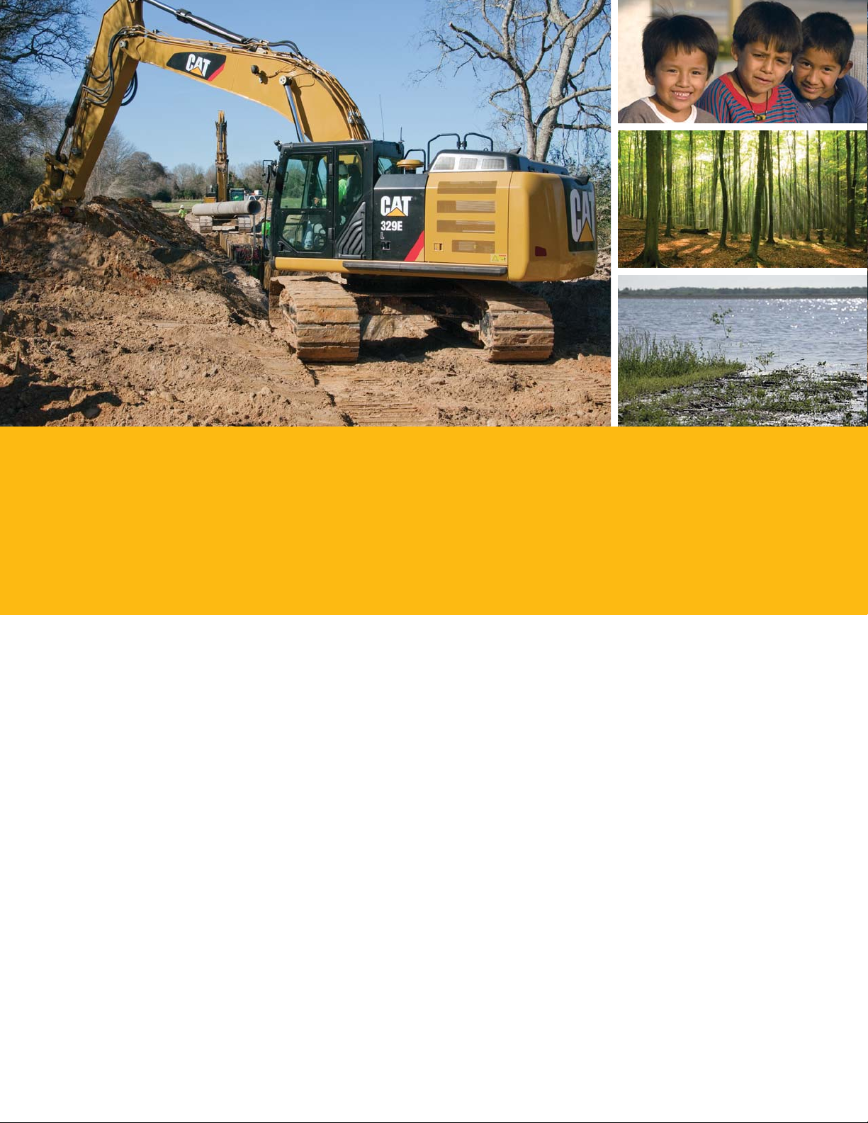
• The 329E is an efcient, productive machine that’s designed to conserve our natural resources
forgenerations ahead.
14
Page 15

329E Hydraulic Excavator Specications
Engine Hydraulic System Service Re ll Capacities
Engine Model Cat® C7.1 ACERT™ Main System – 494 L/min 130 gal/min Fuel Tank Capacity 520 L 137.37 gal
Net Power – 173 kW 232 hp Cooling System 44 L 11.62 gal
SAEJ1349/ISO9249
Gross Power – 180 kW 241 hp (with lter)
SAEJ1995
Bore 105 mm 4.13 in
Stroke 135 mm 5.31 in
Displacement 7.01 L 428 in (including tank)
Weights
Minimum Operating 29 057 kg 64,060 lb
Weight*
Maximum Operating 31 279 kg 68,958 lb
Weight**
*6.15 m (20'2'') reach boom, R2.65CB2
(8'8") stick, 5.8 mt (6.3 t) counterweight,
1.33 m (1.74 yd) bucket, 700 mm (28")
TG shoes.
** SLR boom, 7.85 m (25'9") stick, 6.75 mt
(7.4 t) counterweight, 0.6 m (0.78 yd)
bucket, 800 mm (32") shoes.
Maximum Flow
(Total)
Swing System – 247 L/min 65 gal/min
Maximum Flow
Maximum Pressure 38 000 kPa 5,511 psi
– Equipment
HeavyLift
Maximum Pressure 35 000 kPa 5,076 psi
–Equipment
Normal
Maximum Pressure 35 000 kPa 5,076 psi
– Travel
Maximum Pressure 27 503 kPa 3,989 psi
– Swing
Pilot System – 23.1 L/min 6.1 gal/min
Maximum Flow
Pilot System – 3920 kPa 569 psi
Maximum Pressure
Boom Cylinder – 140 mm 6 in
Bore
Boom Cylinder – 1407 mm 55 in
Stroke
Stick Cylinder – 150 mm 6 in
Bore
Stick Cylinder – 1646 mm 65 in
Stroke
DB Bucket Cylinder 135 mm 5 in
– Bore
DB Bucket Cylinder 1156 mm 46 in
– Stroke
TB Bucket Cylinder 150 mm 6 in
– Bore
TB Bucket Cylinder 1151 mm 45 in
– Stroke
Drive
Maximum 5.1 km/h 3.2 mph
TravelSpeed
Maximum
DrawbarPull
249 kN 55,977 lbf
Swing Mechanism
Engine Oil 22.5 L 5.94 gal
Swing Drive (each) 10 L 2.64 gal
Final Drive (each) 6 L 1.59 gal
Hydraulic System 310 L 81.89 gal
Hydraulic Tank 155 L 40.95 gal
Track
Number of Shoes (each side)
Long Undercarriage 50
Number of Track Rollers (eachside)
Long Undercarriage 9
Number of Carrier Rollers (eachside)
Long Undercarriage
2
Sound Performance
ISO 6396
Operator Noise (Closed) 72 dB(A)
Operator Noise (Open) 77 dB(A)
ISO 6395
Spectator Noise 105 dB(A)
• When properly installed and maintained,
the cab offered by Caterpillar, when tested
with doors and windows closed according
to ANSI/SAE J1166 OCT98, meets OSHA
and MSHA requirements for operator
sound exposure limits in effect at time
ofmanufacture.
• Hearing protection may be needed when
operating with an open operator station
and cab (when not properly maintained or
doors/windows open) for extended periods
or in noisy environment.
Standards
Brakes ISO 10265 2008
Cab/FOGS ISO 10262 1998
Swing Speed 9.8 rpm
Swing Torque 82.2 kN·m 60,628 lb ft
15
Page 16
329E Hydraulic Excavator Specications
Dimensions
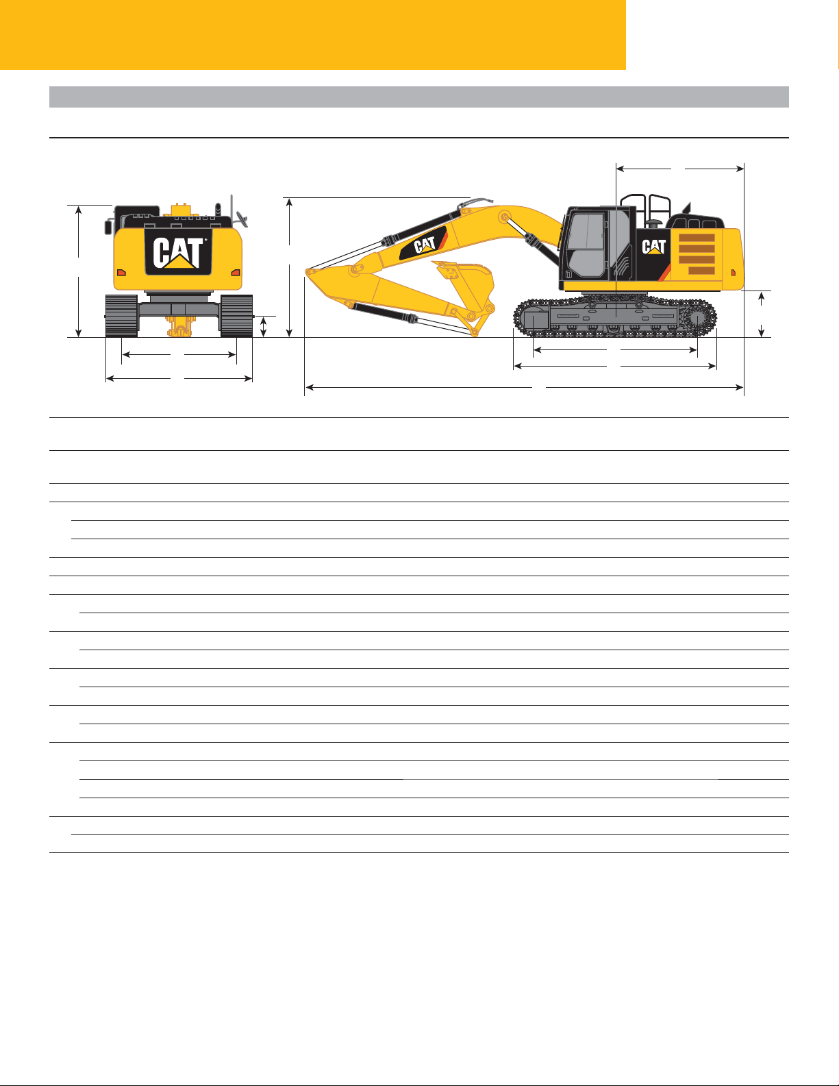
All dimensions are approximate.
3
9
1
6
7
4
5
8
HD Reach Booms Mass Boom Super Long Reach Boom
6.15 m (20'2") 5.55 m (18'3") 10.2 m (33'6")
Stick R3.2CB2 R2.65CB2 M2.5DB Super Long Reach
(10'6") (8'8") (8'2") 7.85 m (25'9")
mm (ft) mm (ft) mm (ft) mm (ft)
Shipping Height* 3372 (11'1") 3450 (11'4") 3520 (11'7") 3229 (10'7")
1
Shipping Height with Guard Rail 3328 (10'11") 3328 (10'11") 3328 (10'11") 3328 (10'11")
Shipping Height with Top Guard 3240 (10'8") 3240 (10'8") 3240 (10'8") 3240 (10'8")
Shipping Length 10 386 (34'1") 10 400 (34'1") 9830 (32'3") 14 443 (47'5")
2
Tail Swing Radius 3044 (10'0") 3044 (10'0") 3044 (10'0") 3044 (10'0")
3
Length to Center of Rollers
4
Long Undercarriage 3994 (13'1") 3994 (13'1") 3994 (13'1") 3994 (13'1")
Track Length
5
Long Undercarriage 4860 (15'11") 4860 (15'11") 4860 (15'11") 4860 (15'11")
Ground Clearance
6
Long Undercarriage 490 (1'7") 490 (1'7") 490 (1'7") 490 (1'7")
Track Gauge
7
Long Undercarriage 2590 (8'6") 2590 (8'6") 2590 (8'6") 2590 (8'6")
Transport Width
8
Long Undercarriage – 600 mm (24") Shoes 3190 (10'6") 3190 (10'6") 3190 (10'6") 3190 (10'6")
Long Undercarriage – 700 mm (28") Shoes 3290 (10'10") 3290 (10'10") 3290 (10'10") 3290 (10'10")
Long Undercarriage – 800 mm (32") Shoes 3390 (11'1") 3390 (11'1") 3390 (11'1") 3390 (11'1")
Cab Height 3044 (10'0") 3044 (10'0") 3044 (10'0") 3044 (10'0")
9
Cab Height with Top Guard 3240 (10'8") 3240 (10'8") 3240 (10'8") 3240 (10'8")
Counterweight Clearance** 1134 (3'9") 1134 (3'9") 1134 (3'9") 1134 (3'9")
10
2
10
*Including shoe lug height.
**Without shoe lug height.
16
Page 17
Working Ranges
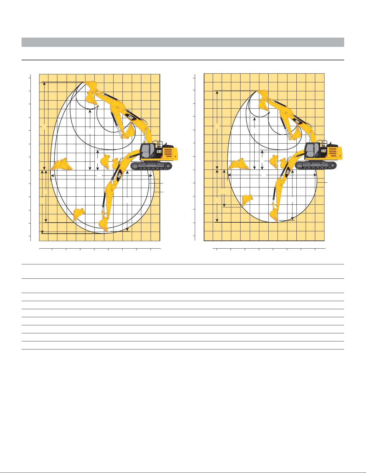
All dimensions are approximate.
Feet
35
30
25
20
15
10
5
0
5
10
15
20
25
Meters
11
10
9
8
7
6
3
5
4
3
2
1
0
1
2
7
3
1
4
5
6
7
8
11 10 9 8 7 6 5 4 3 2 1 0 1
4
5
2
6
35 30 25 20 15 10 5 0 Feet
R2.65CB2
(8'8")
R3.2CB2
(10'6")
Meters
Feet
35
30
25
20
15
10
5
0
5
10
15
20
25
Meters
11
10
9
8
7
6
3
5
4
3
2
1
0
1
2
3
4
5
6
7
8
7
1
4
5
2
6
11 10 9 8 7 6 5 4 3 2 1 0 1
35 30 25 20 15 10 5 0 Feet
M2.5DB
(8'2")
Meters
Stick
Maximum Digging Depth
1
Maximum Reach at Ground Level
2
Maximum Cutting Height
3
Maximum Loading Height
4
Minimum Loading Height
5
Maximum Depth Cut for 2440 mm (8'0") Level Bottom
6
Maximum Vertical Wall Digging Depth
7
HD Reach Booms
6.15 m (20'2")
R3.2CB2 R2.65CB2
(10'6") (8'8")
mm (ft) mm (ft)
7250 (23'9") 6700 (22'0")
10 680 (35'0") 10 200 (33'6")
10 010 (32'10") 9900 (32'6")
6950 (22'10") 6800 (22'4")
2290 (7'6") 2840 (9'4")
7090 (23'3") 6520 (21'5")
5980 (19'7") 5680 (18'8")
Mass Boom
5.55 m (18'3")
M2.5DB
(8'2")
mm (ft)
6100 (20'0")
9430 (30'11")
9130 (29'11")
6000 (19'8")
2470 (8'1")
5910 (19'5")
4250 (13'11")
17
Page 18
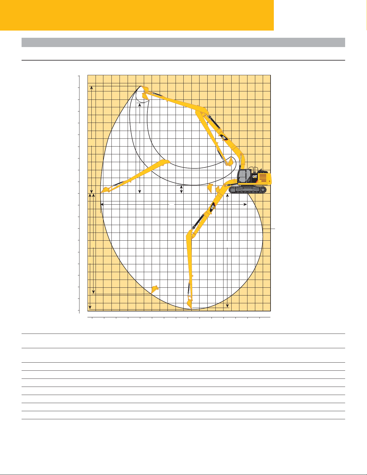
Working Ranges
All dimensions are approximate.
Feet Meters
15
50
14
45
13
12
40
11
35
10
99
30
88
25
77
3
66
20
55
15
44
10
3
2
5
1
0
0
1
5
2
10
3
4
15
5
20
6
7 6
7
25
8
1
30
9
10
35
11
40
12
13
45
14
50
15
19 18 17 16 15 14 13 12 11 10 9
65 60 55 50 45 40 35 30 25 20 15 10 5 0 -5
4
329E Hydraulic Excavator Specications
5
2
8 7 6 5 4
3 2 1 0 -1 -2
7.85 m (25'9")
Meters
Feet
Maximum Digging Depth
1
Maximum Reach at Ground Level
2
Maximum Cutting Height
3
Maximum Loading Height
4
Minimum Loading Height
5
Maximum Depth Cut for 2440 mm (8'0") Level Bottom
6
Maximum Vertical Wall Digging Depth
7
18
Super Long Reach Boom
10.2 m (33'6")
Super Long Reach Stick
7.85 m (25'9")
mm (ft)
14 750 (48'5")
18 420 (60'5")
13 620 (44'8")
11 420 (37'6")
1170 (3'10")
14 650 (48'1")
12 690 (41'8")
Page 19

Operating Weight and Ground Pressure
800 mm (32") 700 mm (28")
Triple Grouser Shoes Triple Grouser Shoes
kg (lb) kPa (psi) kg (lb) kPa (psi)
Long Undercarriage
HD Reach Boom – 6.15 m (20'2")
R3.2CB2 HD (10'6") 29 827 (65,757) 45.8 (6.64) 29 207 (64,390) 51.2 (7.43)
R2.65CB2 HD (8'8") 29 677 (65,427) 45.5 (6.60) 29 057 (64,060) 51.0 (7.40)
Mass Boom – 5.55 m (18'3")
M2.5DB (8'2") 30 117 (66,397) 46.2 (6.70) 29 497 (65,030) 51.7 (7.50)
Super Long Reach Boom – 10.2 m (33'6")
Super Long Reach – 7.85 m (25'9") 31 279 (68,958) 48.0 (6.96) 30 659 (67,591) 53.8 (7.80)
Major Component Weights
kg lb
Base Machine (with boom cylinder, without counterweight, front linkage and track)
Long Undercarriage 15 500 34,180
Counterweight
5.8 mt (6.3 t) 5810 12,810
6.75 mt (7.4 t) 6750 14,880
Boom (includes lines, pins and stick cylinder)
HD Reach Boom – 6.15 m (20'2") 1950 4,300
Mass Boom – 5.55 m (18'3") 2020 4,450
Super Long Reach – 10.2 m (33'6") 2800 6,170
Stick (includes lines, pins and bucket cylinder)
R3.2CB2 (10'6") HD 980 2,160
R2.65CB2 (8'8") HD 830 1,830
M2.5DB (8'2") 1020 2,250
Super Long Reach 1400 3,090
Track Shoe (Long/per two tracks)
700 mm (28") Triple Grouser 3920 8,640
700 mm (28") Triple Grouser Heavy Duty 4280 9,440
800 mm (32") Triple Grouser 4540 10,020
Buckets
CB1 1200HD – 1.33 m (1.74 yd) 1047 2,309
CB1 1350HD – 1.54 m (2.01 yd) 1096 2,416
DB 1500GD – 1.87 m (2.45 yd) 1227 2,705
A 1145DC – 0.6 m (0.78 yd) 288.9 637
All weights are rounded up to nearest 10 kg and lb except for buckets. Kg and lb were rounded up separately so some of the kg and lb do not match.
Base machine includes 75 kg (165 lb) operator weight, 90% fuel weight, and undercarriage with center guard.
700 mm (28") triple grouser heavy duty track shoe is not used in the calculation for operating weight and ground pressure.
19
Page 20

Bucket and Stick Forces
329E Hydraulic Excavator Specications
HD Reach Booms Mass Boom Boom
6.15 m (20'2") 5.55 m (18'3") 10.2 m (33'6")
CB-Family Bucket DB-Family Bucket A-Family Bucket
Stick R3.2CB2 R2.65CB2 M2.5DB Super Long Reach
(10'6") (8'8") (8'2") 7.85 m (25'9")
kN (lbf) kN (lbf) kN (lbf) kN (lbf)
General Duty
Bucket Digging Force (ISO) 180 (40,500) 180 (40,500) 212 (47,700) –
Stick Digging Force (ISO) 126 (28,300) 145 (32,600) 153 (34,400) –
Bucket Digging Force (SAE) 161 (36,200) 161 (36,200) 188 (42,300) –
Stick Digging Force (SAE) 123 (27,700) 141 (31,700) 148 (33,300) –
General Duty Capacity
Bucket Digging Force (ISO) 175 (39,300) 175 (39,300) – –
Stick Digging Force (ISO) 125 (28,100) 143 (32,100) – –
Bucket Digging Force (SAE) 158 (35,500) 158 (35,500) – –
Stick Digging Force (SAE) 122 (27,400) 139 (31,200) – –
Heavy Duty
Bucket Digging Force (ISO) 179 (40,200) 179 (40,200) 210 (47,200) –
Stick Digging Force (ISO) 126 (28,300) 145 (32,600) 152 (34,200) –
Bucket Digging Force (SAE) 158 (35,500) 158 (35,500) 185 (41,600) –
Stick Digging Force (SAE) 123 (27,700) 140 (31,500) 147 (33,000) –
Heavy Duty – Power
Bucket Digging Force (ISO) 196 (44,100) 196 (44,100) – –
Stick Digging Force (ISO) 128 (28,800) 147 (33,000) – –
Bucket Digging Force (SAE) 172 (38,700) 172 (38,700) – –
Stick Digging Force (SAE) 124 (27,900) 141 (31,700) – –
Severe Duty
Bucket Digging Force (ISO) 179 (40,200) 179 (40,200) – –
Stick Digging Force (ISO) 126 (28,300) 145 (32,600) – –
Bucket Digging Force (SAE) 158 (35,500) 158 (35,500) – –
Stick Digging Force (SAE) 123 (27,700) 140 (31,500) – –
Ditch Cleaning
Bucket Digging Force (ISO) – – – 60.49 (13,600)
Stick Digging Force (ISO) – – – 45.16 (10,150)
Super Long Reach
20
Page 21
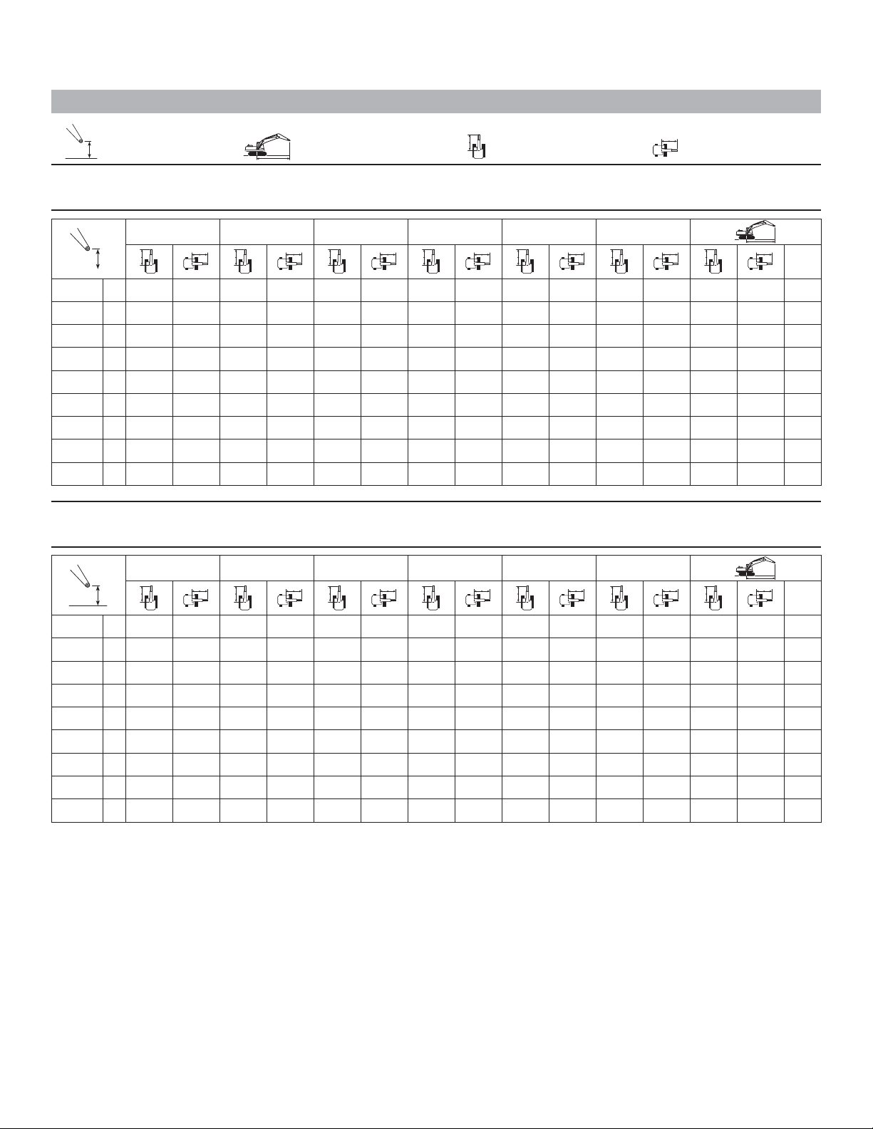
HD Reach Boom Lift Capacities
Load Point Height Load at Maximum Reach Load Radius Over Front Load Radius Over Side
Boom – 6.15 m (20'2") Counterweight – 5.8 mt (6.3 t) Bucket – None
Stick – R3.2CB2 (10'6") Shoes – 800 mm (32") triple grouser with step
1.5 m/5.0 ft 3.0 m/10.0 ft 4.5 m/15.0 ft 6.0 m/20.0 ft 7.5 m/25.0 ft 9.0 m/30.0 ft
7.5 m kg
25.0 ft lb
6.0 m kg
20.0 ft lb
4.5 m kg
15.0 ft lb
3.0 m kg
10.0 ft lb
1.5 m kg
5.0 ft lb
Ground
Line
–1.5 m kg
–5.0 ft lb
–3.0 m kg
–10.0 ft lb
–4.5 m kg
–15.0 ft lb
*9200 8500 *8350 6100 *5300 4700 8.82
*14 150 12 400 *10 750 8150 9050 5900 *6500 4500 *5450 4400 9.13
*30,450 26,700 *23,250 17,550 19,400 12,650 *12,000 9,650 29.95
*16 900 11 650 *12 200 7750 8800 5700 6750 4400 *5800 4250 9.19
kg
lb
*6750 *6750 *10 600 *10 600 *18 150 11 200 11 950 7400 8600 5500 7200 4650 8.52
*15,050 *15,050 *24,050 *24,050 *39,350 24,100 25,700 15,950 18,450 11,800 15,800 10,250 27.93
*12 100 *12 100 *17 150 *17 150 *17 050 11 250 12 000 7450 8600 5500 8250 5300 7.74
*27,150 *27,150 *38,900 *38,900 *36,900 24,250 25,750 16,000 18,600 11,900 18,300 11,750 25.28
*19 750 *19 750 *14 500 11 500 *10 750 7600 *9400 6850 6.51
*42,500 *42,500 *31,150 24,750 *22,750 16,400 *20,700 15,300 21.13
*36,450 25,100 *26,400 16,750 18,950 12,250 *13,700 9,450 *12,700 9,350 30.15
*18 150 11 300 12 100 7550 8650 5550 *6350 4350 8.99
*39,300 24,300 26,000 16,200 18,600 11,950 *14,000 9,550 29.50
*19,950 18,350 *18,200 13,050 *11,650 10,350 28.88
*7850 6200 *5350 5300 8.23
*16,700 13,300 *11,750 *11,750 26.83
Boom – 6.15 m (20'2") Counterweight – 5.8 mt (6.3 t) Bucket – None
Stick – R3.2CB2 (10'6") Shoes – 700 mm (28") triple grouser
*12,400 *12,400 23.54
m
ft
*5600 *5600 7.27
6.0 m/20.0 ft
*5600 *5600 7.27
*7850 6100 *5350 5250 8.23
*9200 8400 *8350 5950 *5300 4600 8.82
*19,950 18,050 *18,200 12,850 *11,650 10,200 28.88
*16,700 13,100 *11,750 11,600 26.83
*12,400 *12,400 23.54
7.5 m kg
25.0 ft lb
6.0 m kg
20.0 ft lb
4.5 m kg
15.0 ft lb
3.0 m kg
10.0 ft lb
1.5 m kg
5.0 ft lb
Ground
Line
–1.5 m kg
–5.0 ft lb
–3.0 m kg
–10.0 ft lb
–4.5 m kg
–15.0 ft lb
1.5 m/5.0 ft 3.0 m/10.0 ft 4.5 m/15.0 ft 7.5 m/25.0 ft 9.0 m/30.0 ft
*14 150 12 200 *10 750 8000 8850 5800 *6500 4400 *5450 4300 9.13
*30,450 26,250 *23,250 17,250 19,050 12,450 *12,000 9,450 29.95
*16 900 11 450 12 150 7650 8650 5600 6600 4300 *5800 4200 9.19
kg
lb
*6750 *6750 *10 600 *10 600 *18 150 11 000 11 750 7250 8400 5400 7050 4550 8.52
*15,050 *15,050 *24,050 *24,050 *39,350 23,650 25,200 15,650 18,100 11,600 15,500 10,050 27.93
*12 100 *12 100 *17 150 *17 150 *17 050 11 050 11 750 7300 8450 5400 8100 5200 7.74
*27,150 *27,150 *38,900 *38,900 *36,900 23,800 25,250 15,700 18,200 11,700 17,950 11,550 25.28
*19 750 *19 750 *14 500 11 300 *10 750 7450 *9400 6700 6.51
*42,500 *42,500 *31,150 24,300 *22,750 16,100 *20,700 15,000 21.13
*36,450 24,700 26,100 16,450 18,600 12,050 *13,700 9,250 *12,700 9,200 30.15
*18 150 11 100 11 850 7400 8500 5450 *6350 4250 8.99
*39,300 23,850 25,500 15,900 18,250 11,700 *14,000 9,350 29.50
*Indicates that the load is limited by hydraulic lifting capacity rather than tipping load. The above loads are in compliance with hydraulic excavator lift capacity
standard ISO 10567:2007. They do not exceed 87% of hydraulic lifting capacity or 75% of tipping load. Weight of all lifting accessories must be deducted from the
above lifting capacities. Lifting capacities are based on the machine standing on a firm, uniform supporting surface. The use of a work tool attachment point to
handle/lift objects, could affect the machine lift performance.
Always refer to the appropriate Operation and Maintenance Manual for specific product information.
m
ft
21
Page 22
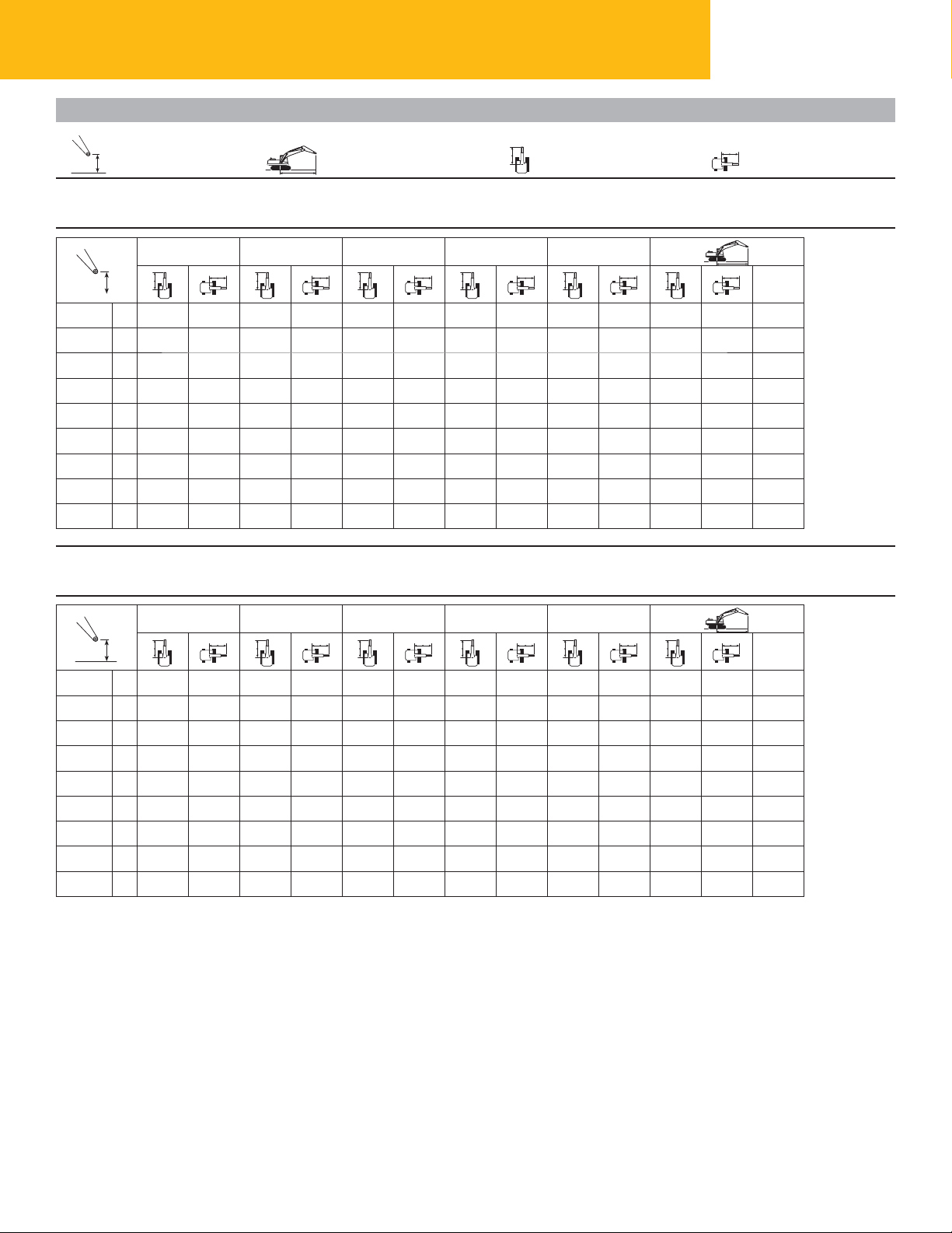
329E Hydraulic Excavator Specications
HD Reach Boom Lift Capacities
Load Point Height Load at Maximum Reach Load Radius Over Front Load Radius Over Side
Boom – 6.15 m (20'2") Counterweight – 5.8 mt (6.3 t) Bucket – None
Stick – R2.65CB2 (8'8") Shoes – 800 mm (32") triple grouser with step
1.5 m/5.0 ft 3.0 m/10.0 ft 4.5 m/15.0 ft 6.0 m/20.0 ft 7.5 m/25.0 ft
7.5 m kg
25.0 ft lb
6.0 m kg
20.0 ft lb
4.5 m kg
15.0 ft lb
3.0 m kg
10.0 ft lb
1.5 m kg
5.0 ft lb
Ground
Line
–1.5 m kg
–5.0 ft lb
–3.0 m kg
–10.0 ft lb
–4.5 m kg
–15.0 ft lb
kg
lb
*19,150 18,950 *16,300 *16,300 21.52
*8900 8750 *8350 6150 *6900 5900 7.70
*12 250 *12 250 *10 000 8450 *8950 6050 *6850 5150 8.33
*26,350 *26,350 *21,700 18,200 *19,550 13,050 *15,050 11,350 27.26
*15 450 12 200 *11 450 8100 9050 5900 *7000 4750 8.66
*33,250 26,300 *24,800 17,450 19,400 12,700 *15,400 10,500 28.40
*16 500 11 600 12 350 7800 8850 5750 7100 4650 8.72
*38,400 25,000 26,600 16,750 19,000 12,350 15,600 10,200 28.61
*17 550 11 350 12 150 7600 8700 5600 7300 4750 8.51
*10 350 *10 350 *17 950 11 350 12 050 7500 8700 5600 7950 5150 8.01
*23,600 *23,600 *38,950 24,400 25,950 16,200 18,700 12,050 17,500 11,350 26.26
*19 400 *19 400 *16 400 11 450 12 150 7600 9350 6000 7.17
*44,200 *44,200 *35,450 24,700 26,100 16,350 20,750 13,350 23.42
*17 250 *17 250 *13 100 11 750 *9550 8150 5.83
*40,000 24,450 26,100 16,350 18,750 12,100 16,050 10,450 27.92
*27,900 25,350 *20,900 18,400 18.85
*19,450 18,800 *15,750 13,200 *15,250 13,100 25.08
*7350 *7350 6.67
m
ft
Boom – 6.15 m (20'2") Counterweight – 5.8 mt (6.3 t) Bucket – None
Stick – R2.65CB2 (8'8") Shoes – 700 mm (28") triple grouser
1.5 m/5.0 ft 3.0 m/10.0 ft 4.5 m/15.0 ft 7.5 m/25.0 ft
7.5 m kg
25.0 ft lb
6.0 m kg
20.0 ft lb
4.5 m kg
15.0 ft lb
3.0 m kg
10.0 ft lb
1.5 m kg
5.0 ft lb
Ground
Line
–1.5 m kg
–5.0 ft lb
–3.0 m kg
–10.0 ft lb
–4.5 m kg
–15.0 ft lb
kg
lb
*10 350 *10 350 *17 950 11 150 11 850 7400 8500 5500 7800 5050 8.01
*23,600 *23,600 *38,950 23,950 25,450 15,900 18,350 11,800 17,150 11,100 26.26
*19 400 *19 400 *16 400 11 250 11 900 7450 9200 5900 7.17
*44,200 *44,200 *35,450 24,250 25,600 16,050 20,350 13,100 23.42
*17 250 *17 250 *13 100 11 550 *9550 8050 5.83
*12 250 *12 250 *10 000 8300 *8950 5950 *6850 5050 8.33
*26,350 *26,350 *21,700 17,900 19,400 12,800 *15,050 11,150 27.26
*15 450 12 000 *11 450 7950 8850 5800 *7000 4700 8.66
*33,250 25,850 *24,800 17,150 19,050 12,450 *15,400 10,300 28.40
*16 500 11 400 12 150 7650 8700 5650 6950 4550 8.72
*38,400 24,550 26,100 16,450 18,650 12,100 15,300 10,050 28.61
*17 550 11 150 11 900 7450 8550 5500 7150 4650 8.51
*40,000 24,000 25,600 16,050 18,400 11,850 15,750 10,250 27.92
*27,900 24,900 *20,900 18,050 18.85
*Indicates that the load is limited by hydraulic lifting capacity rather than tipping load. The above loads are in compliance with hydraulic excavator lift capacity
standard ISO 10567:2007. They do not exceed 87% of hydraulic lifting capacity or 75% of tipping load. Weight of all lifting accessories must be deducted from the
above lifting capacities. Lifting capacities are based on the machine standing on a firm, uniform supporting surface. The use of a work tool attachment point to
handle/lift objects, could affect the machine lift performance.
Always refer to the appropriate Operation and Maintenance Manual for specific product information.
6.0 m/20.0 ft
m
ft
*19,150 18,650 *16,300 *16,300 21.52
*8900 8600 *8350 6050 *6900 5800 7.70
*19,450 18,500 *15,750 12,950 *15,250 12,900 25.08
*7350 7300 6.67
22
Page 23
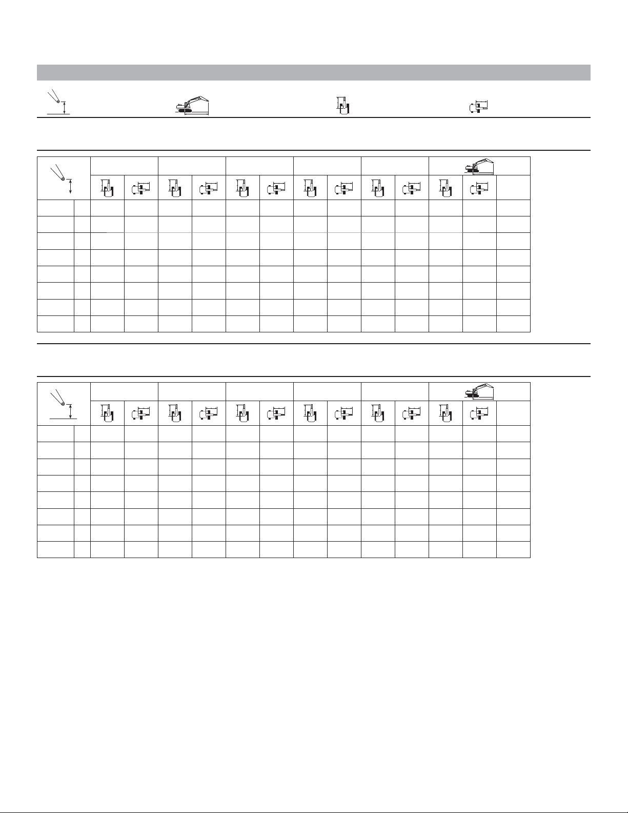
Mass Boom Lift Capacities
Load Point Height Load at Maximum Reach Load Radius Over Front Load Radius Over Side
Boom – 5.55 m (18'3") Counterweight – 5.8 mt (6.3 t) Bucket – None
Stick – M2.5DB (8'2") Shoes – 800 mm (32") triple grouser with step
1.5 m/5.0 ft 3.0 m/10.0 ft 4.5 m/15.0 ft 6.0 m/20.0 ft 7.5 m/25.0 ft
7.5 m kg
25.0 ft lb
6.0 m kg
20.0 ft lb
4.5 m kg
15.0 ft lb
3.0 m kg
10.0 ft lb
1.5 m kg
5.0 ft lb
Ground
Line
–1.5 m kg
–5.0 ft lb
–3.0 m kg
–10.0 ft lb
kg
lb
*12 250 *12 250 *10 400 8400 *8000 6000 7.43
*26,450 *26,450 *22,650 18,100 *17,600 13,300 24.31
*15 200 12 350 *11 650 8100 8950 5800 *8300 5450 7.80
*32,700 26,600 *25,300 17,400 19,250 12,500 *18,300 12,050 25.57
*17 550 11 700 12 400 7750 8800 5650 8200 5300 7.87
*37,900 25,200 26,600 16,700 18,900 12,200 18,050 11,650 25.81
*18 400 11 400 12 150 7550 8700 5600 8500 5450 7.63
*17 350 *17 350 *17 750 11 350 12 100 7500 9450 6050 7.08
*39,450 *39,450 *38,450 24,400 26,000 16,150 20,900 13,300 23.17
*21 150 *21 150 *15 550 11 500 *11 200 7650 *10 900 7500 6.10
*45,750 *45,750 *33,500 24,750 *24,000 16,600 19.88
*39,800 24,500 26,100 16,300 18,700 12,000 18,700 12,000 25.04
*9650 8650 *8050 7150 6.71
*21,200 18,550 *17,750 16,050 21.82
Boom – 5.55 m (18'3") Counterweight – 5.8 mt (6.3 t) Bucket – None
Stick – M2.5DB (8'2") Shoes – 700 mm (28") triple grouser
*8650 *8650 5.49
*19,250 *19,250 17.60
m
ft
6.0 m/20.0 ft
m
ft
*8650 *8650 5.49
*9650 8500 *8050 7050 6.71
*21,200 18,200 *17,750 15,750 21.82
*19,250 *19,250 17.60
7.5 m kg
25.0 ft lb
6.0 m kg
20.0 ft lb
4.5 m kg
15.0 ft lb
3.0 m kg
10.0 ft lb
1.5 m kg
5.0 ft lb
Ground
Line
–1.5 m kg
–5.0 ft lb
–3.0 m kg
–10.0 ft lb
1.5 m/5.0 ft 3.0 m/10.0 ft 4.5 m/15.0 ft 7.5 m/25.0 ft
*12 250 *12 250 *10 400 8250 *8000 5900 7.43
*26,450 *26,450 *22,650 17,800 *17,600 13,050 24.31
*15 200 12 150 *11 650 7950 8800 5700 8250 5350 7.80
*32,700 26,150 *25,300 17,100 18,900 12,250 18,200 11,850 25.57
*17 550 11 500 *12 150 7600 8650 5550 8050 5200 7.87
kg
lb
*17 350 *17 350 *17 750 11 150 11 850 7350 9300 5900 7.08
*39,450 *39,450 *38,450 23,950 25,500 15,850 20,500 13,050 23.17
*21 150 *21 150 *15 550 11 300 *11 200 7500 *10 900 7350 6.10
*45,750 *45,750 *33,500 24,300 *24,000 16,300 19.88
*37,900 24,750 26,100 16,400 18,550 11,950 17,700 11,450 25.81
*18 400 11 200 11 900 7400 8550 5450 8300 5350 7.63
*39,800 24,050 25,600 16,000 18,350 11,800 18,300 11,750 25.04
*Indicates that the load is limited by hydraulic lifting capacity rather than tipping load. The above loads are in compliance with hydraulic excavator lift capacity
standard ISO 10567:2007. They do not exceed 87% of hydraulic lifting capacity or 75% of tipping load. Weight of all lifting accessories must be deducted from the
above lifting capacities. Lifting capacities are based on the machine standing on a firm, uniform supporting surface. The use of a work tool attachment point to
handle/lift objects, could affect the machine lift performance.
Always refer to the appropriate Operation and Maintenance Manual for specific product information.
23
Page 24
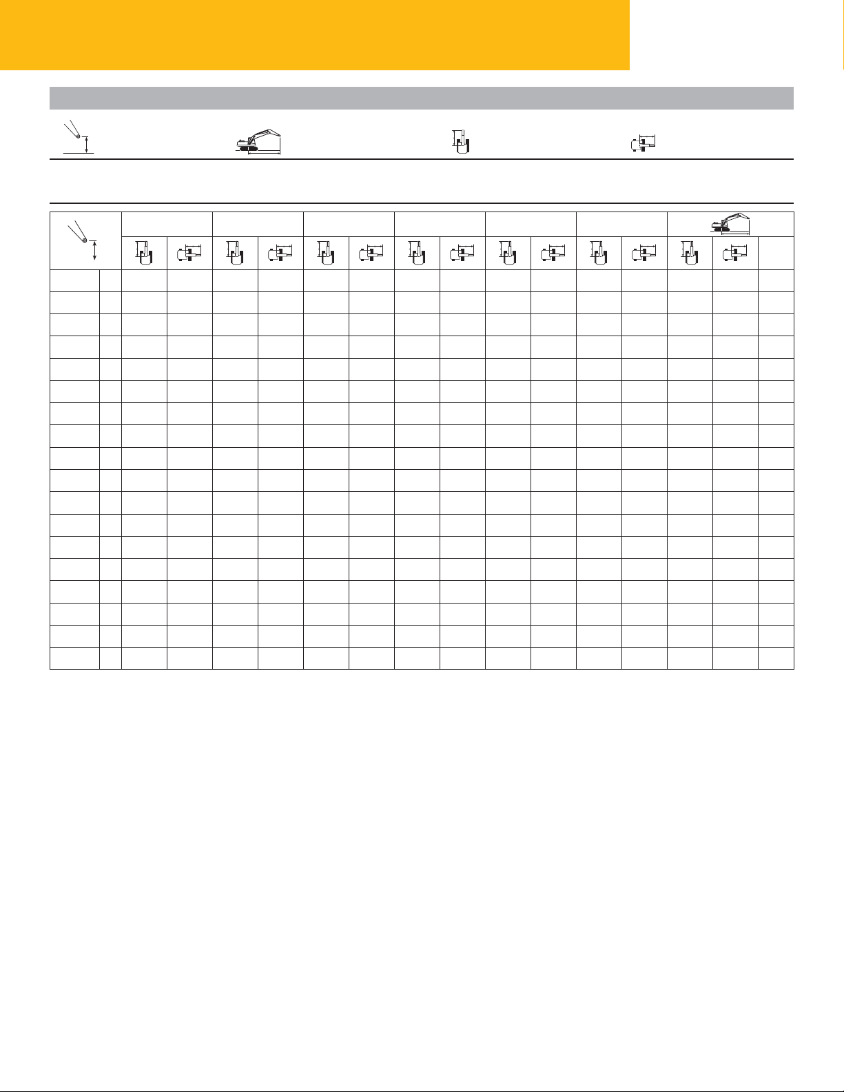
329E Hydraulic Excavator Specications
Super Long Reach Boom Lift Capacities
Load Point Height Load at Maximum Reach Load Radius Over Front Load Radius Over Side
Boom – 10.2 m (33'6") Counterweight – 6.75 mt (7.4 t) Bucket – None
Stick – 7.85 m (25'9") Super Long Reach Shoes – 800 mm (32") triple grouser with step
1.5 m/5.0 ft 3.0 m/10.0 ft 4.5 m/15.0 ft 6.0 m/20.0 ft 7.5 m/25.0 ft 9.0 m/30.0 ft
12.0 m kg
40.0 ft lb
10.5 m kg
35.0 ft lb
9.0 m kg
30.0 ft lb
7.5 m kg
25.0 ft lb
6.0 m kg
20.0 ft lb
4.5 m kg
15.0 ft lb
3.0 m kg
10.0 ft lb
1.5 m kg
5.0 ft lb
Ground kg
Line
–1.5 m kg
–5.0 ft lb
–3.0 m kg
–10.0 ft lb
–4.5 m kg
–15.0 ft lb
–6.0 m kg
–20.0 ft lb
–7.5 m kg
–25.0 ft lb
–9.0 m kg
–30.0 ft lb
–10.5 m kg
–35.0 ft lb
–12.0 m kg
–40.0 ft lb
–13.5 m kg
lb
*1650 *1650 *2150 *2150 *3550 *3550 *6500 7900 4750 6150 3800 *1550 1500 16.95
*3,600 *3,600 *4,800 *4,800 *8,000 *8,000 *14,950 17,050 10,250 13,300 8,100 *3,400 3,250 55.60
*2250 *2250 *2750 *2750 *3900 *3900 *6250 7650 4550 5950 3600 *1650 1500 16.58
*4,950 *4,950 *6,100 *6,100 *8,750 *8,750 *14,250 16,450 9,750 12,850 7,700 *3,650 3,300 54.34
*2850 *2850 *3350 *3350 *4450 *4450 *6550 7500 4400 5850 3450 *1850 1600 16.05
*6,300 *6,300 *7,500 *7,500 *10,000 *10,000 *14,950 16,150 9,450 12,550 7,450 *4,050 3,450 52.56
*3450 *3450 *4050 *4050 *5150
*7,700 *7,700 *9,050 *9,050 *11,650 *11,650 *16,500 16,050 9,350 12,450 7,350 *4,600 3,700 50.22
*4150 *4150 *4800 *4800 *6000 *6000 *8250 7500 4350 5800 3400 *2400 1850 14.47
*9,250 *9,250 *10,800 *10,800 *13,600 *13,600 *18,800 16,100 9,400 12,450 7,350 *5,350 4,100 47.23
*4850 *4850 *5650 *5650 *7050 *7050 *9650 7550 4450 5850 3450 *2950 2100 13.36
*10,900 *10,900 *12,750 *12,750 *15,950 *15,950 *22,100 16,300 9,600 12,600 7,500 *6,600 4,700 43.45
*5650 *5650 *6650 *6650 *8350 8350 *9950 7750 4600 5950 3600 *3900 2550 11.96
*12,700 *12,700 *15,000 *15,000 *19,000 *19,000 *21,300 16,700 9,950 12,900 7,750 *8,900 5,700 38.66
*4150 *4150 *4650 *4650 *1350 *1350 17.27
*1550 *1550 *5200
*3,550 *3,550 *12,200 *12,200 *17,800 *13,850 12,050 *11,550 9,400 *3,000 *3,000 56.74
*1650 *1650 *3600 *3600 *8250 *7350 5100 *6000 4050 *1450 *1450 17.19
*3,750 *3,750 *8,250 *8,250 *19,300 *15,850 11,050 *12,950 8,700 *3,150 *3,150 56.40
*7800 *7800 *10 100 *10 100 *8650 *7050 4850 *5800 3800 *4900 3300 10.15
*17,700 *17,700 *23,200 22,050 *18,350 *14,850 10,500 *12,100 8,250 *10,850 7,550 32.40
*5200 *8300 *6400 5600 *5350 4350 *1400 *1400 17.29
*5150 *7250 7450 4350 5800 3400 *2050 1700 15.36
7500
16,200
6750
14,600
6300
13,550
6050
13,000
5900
12,700
5900
12,700
5950
12,800
6100
13,150
6300
13,600
6600
14,300
*10,100 *10,100 *2,900 *2,900 56.63
m
ft
*1350 *1350 14.02
*2,950 *2,950 45.54
*1300 *1300 15.00
*2,800 *2,800 48.88
*1250 *1250 15.77
*2,750 *2,750 51.52
*1250 *1250 16.37
*2,750 *2,750 53.56
*1250 *1250 16.81
*2,750 *2,750 55.06
*1300 *1300 17.10
*2,800 *2,800 56.08
*5550 *5550 7.10
*Indicates that the load is limited by hydraulic lifting capacity rather than tipping load. The above loads are in compliance with hydraulic excavator lift capacity
standard ISO 10567:2007. They do not exceed 87% of hydraulic lifting capacity or 75% of tipping load. Weight of all lifting accessories must be deducted from the
above lifting capacities. Lifting capacities are based on the machine standing on a firm, uniform supporting surface. The use of a work tool attachment point to
handle/lift objects, could affect the machine lift performance.
Always refer to the appropriate Operation and Maintenance Manual for specific product information.
24
Page 25
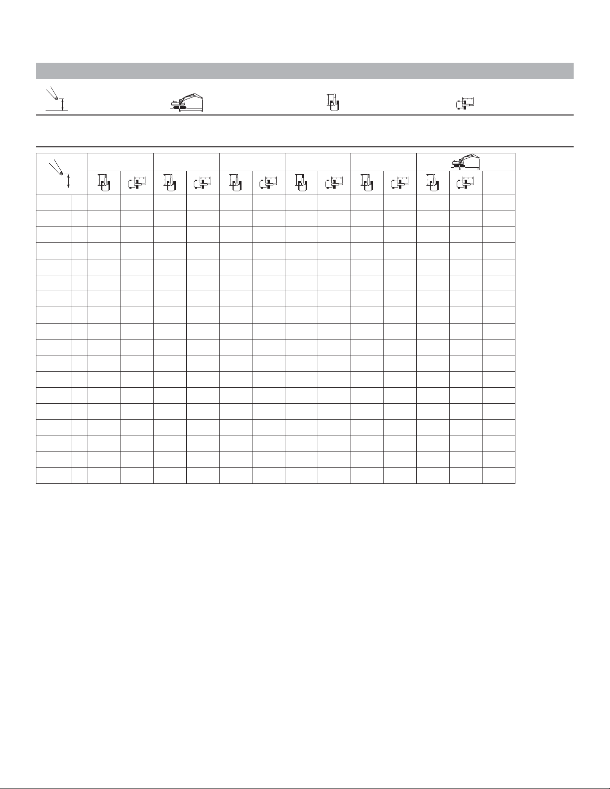
Super Long Reach Boom Lift Capacities
Load Point Height Load at Maximum Reach Load Radius Over Front Load Radius Over Side
Boom – 10.2 m (33'6") Counterweight – 6.75 mt (7.4 t) Bucket – None
Stick – 7.85 m (25'9") Super Long Reach Shoes – 800 mm (32") triple grouser with step
10.5 m/35.0 ft 12.0 m/40.0 ft 13.5 m/45.0 ft 15.0 m/50.0 ft 16.5 m/55.0 ft
12.0 m kg *1350 *1350 14.02
40.0 ft lb *3,350 *3,350 *2,950 *2,950 45.54
10.5 m kg *1300 *1300 15.00
35.0 ft lb *2,800 *2,800 48.88
9.0 m kg *2050 *2050 *1250 *1250 15.77
30.0 ft lb *3,950 *3,950 *2,750 *2,750 51.52
7.5 m kg *3000 2800 *2550 2300 *1250 *1250 16.37
25.0 ft lb *6,550 6,000 *5,150 4,850 *2,750 *2,750 53.56
6.0 m kg *3150 2750 *2950 2250 *1700 *1700 *1250 *1250 16.81
20.0 ft lb *6,900 5,850 *6,050 4,750 *2,850 *2,850 *2,750 *2,750 55.06
4.5 m kg *3500 3200 *3350 2600 *3300 2150 *2100 1750 *1300 *1300 17.10
15.0 ft lb *7,650 6,900 *7,350 5,600 *6,850 4,550 *3,850 3,750 *2,800 *2,800 56.08
3.0 m kg *4200 3750 *3850 3050 *3600 2500 3300 2050 *2350 1700 *1350 *1350 17.27
10.0 ft lb *9,050 8,050 *8,350 6,500 *7,850 5,350 7,000 4,400 *4,500 3,650 *2,900 *2,900 56.63
1.5 m kg *4650 3500 *4200 2850 3750 2350 3200 2000 *2550 1650 *1400 *1400 17.29
5.0 ft lb *10,100 7,550 *9,100 6,150 8,050 5,050 6,800 4,200 *4,800 3,500 *3,000 *3,000 56.74
Ground
kg *5150 3300 4300 2700 3650 2250 3100 1900 *2550 1600 *1450 *1450 17.19
Line
lb *11,100 7,050 9,250 5,800 7,800 4,800 6,650 4,050 *4,800 3,400 *3,150 *3,150 56.40
–1.5 m kg 5000 3100 4150 2550 3500 2150 3000 1800 *2400 1550 *1550 1500 16.95
–5.0 ft lb 10,750 6,600 8,950 5,500 7,550 4,600 6,500 3,900 *4,150 3,300 *3,400 3,250 55.60
–3.0 m kg 4850 2950 4050 2450 3450 2050 2950 1750 *1850 1550 *1650 1500 16.58
–10.0 ft lb 10,400 6,300 8,700 5,250 7,400 4,450 6,350 3,750 *3,650 3,300 54.34
–4.5 m kg 4750 2850 3950 2350 3400 2000 2950 1750 *1850 1600 16.05
–15.0 ft lb 10,200 6,100 8,500 5,100 7,250 4,300 6,300 3,700 *4,050 3,450 52.56
–6.0 m kg 4700 2800 3900 2350 3350 2000 2950 1750 *2050 1700 15.36
–20.0 ft lb 10,100 6,000 8,450 5,000 7,200 4,300 *4,950 3,750 *4,600 3,700 50.22
–7.5 m kg 4700 2800 3950 2350 3400 2000 *2400 1850 14.47
–25.0 ft lb 10,100 6,000 8,450 5,050 7,300 4,350 *5,350 4,100 47.23
–9.0 m kg 4750 2850 4000 2400 *2950 2100 13.36
–30.0 ft lb 10,200 6,100 8,600 5,150 *6,600 4,700 43.45
–10.5 m kg 4850 2950 *3900 2550 11.96
–35.0 ft lb 10,500 6,400 *8,900 5,700 38.66
–12.0 m kg *4900 3300 10.15
–40.0 ft lb *10,850 7,550 32.40
–13.5 m kg *5550 *5550 7.10
m
ft
*Indicates that the load is limited by hydraulic lifting capacity rather than tipping load. The above loads are in compliance with hydraulic excavator lift capacity
standard ISO 10567:2007. They do not exceed 87% of hydraulic lifting capacity or 75% of tipping load. Weight of all lifting accessories must be deducted from the
above lifting capacities. Lifting capacities are based on the machine standing on a firm, uniform supporting surface. The use of a work tool attachment point to
handle/lift objects, could affect the machine lift performance.
Always refer to the appropriate Operation and Maintenance Manual for specific product information.
25
Page 26
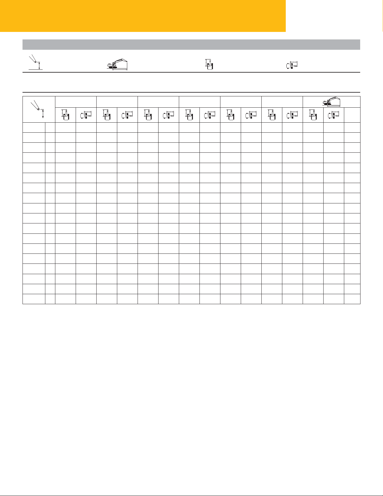
329E Hydraulic Excavator Specications
Super Long Reach Boom Lift Capacities
Load Point Height Load at Maximum Reach Load Radius Over Front Load Radius Over Side
Boom – 10.2 m (33'6") Counterweight – 6.75 mt (7.4 t) Bucket – None
Stick – 7.85 m (25'9") Super Long Reach Shoes – 700 mm (28") triple grouser
1.5 m/5.0 ft 3.0 m/10.0 ft 4.5 m/15.0 ft 6.0 m/20.0 ft 7.5 m/25.0 ft 9.0 m/30.0 ft
12.0 m kg
40.0 ft lb
10.5 m kg
35.0 ft lb
9.0 m kg
30.0 ft lb
7.5 m kg
25.0 ft lb
6.0 m kg
20.0 ft lb
4.5 m kg
15.0 ft lb
3.0 m kg
10.0 ft lb
1.5 m kg
5.0 ft lb
Ground kg
Line
–1.5 m kg
–5.0 ft lb
–3.0 m kg
–10.0 ft lb
–4.5 m kg
–15.0 ft lb
–6.0 m kg
–20.0 ft lb
–7.5 m kg
–25.0 ft lb
–9.0 m kg
–30.0 ft lb
–10.5 m kg
–35.0 ft lb
–12.0 m kg
–40.0 ft lb
–13.5 m kg
lb
*1650 *1650 *2150 *2150 *3550 *3550 *6500 7750 4650 6050 3700 *1550 1450 16.95
*3,600 *3,600 *4,800 *4,800 *8,000 *8,000 *14,950 16,700 10,000 13,000 7,950 *3,400 3,150 55.60
*2250 *2250 *2750 *2750 *3900 *3900 *6250 7500 4400 5850 3500 *1650 1500 16.58
*4,950 *4,950 *6,100 *6,100 *8,750 *8,750 *14,250 16,100 9,500 12,550 7,550 *3,650 3,250 54.34
*2850 *2850 *3350 *3350 *4450 *4450 *6550 7350 4300 5700 3400 *1850 1550 16.05
*6,300 *6,300 *7,500 *7,500 *10,000 *10,000 *14,950 15,800 9,200 12,250 7,250 *4,050 3,350 52.56
*3450 *3450 *4050 *4050 *5150
*7,700 *7,700 *9,050 *9,050 *11,650 *11,650 *16,500 15,650 9,100 12,150 7,150 *4,600 3,600 50.22
*4150 *4150 *4800 *4800 *6000 *6000 *8250 7300 4250 5650 3350 *2400 1800 14.47
*9,250 *9,250 *10,800 *10,800 *13,600 *13,600 *18,800 15,700 9,150 12,150 7,150 *5,350 4,000 47.23
*4850 *4850 *5650 *5650 *7050 *7050 *9650 7400 4350 5700 3400 *2950 2050 13.36
*10,900 *10,900 *12,750 *12,750 *15,950 *15,950 *22,100 15,950 9,350 12,300 7,300 *6,600 4,550 43.45
*5650 *5650 *6650 *6650 *8350 *8350 *9950 7550 4500 5850 3500 *3900 2450 11.96
*12,700 *12,700 *15,000 *15,000 *19,000 *19,000 *21,300 16,350 9,700 12,600 7,600 *8,900 5,550 38.66
*4150 *4150 *4650 4650 *1350 *1350 17.27
*1550 *1550 *5200
*3,550 *3,550 *12,200 *12,200 *17,800 *13,850 11,850 *11,550 9,200 *3,000 *3,000 56.74
*1650 *1650 *3600 *3600 *8250 *7350 5000 *6000 3950 *1450 1450 17.19
*3,750 *3,750 *8,250 *8,250 *19,300 *15,850 10,800 *12,950 8,500 *3,150 3,150 56.40
*7800 *7800 *10 100 10 000 *8650 *7050 4750 *5800 3700 *4900 3200 10.15
*17,700 *17,700 *23,200 21,600 *18,350 *14,850 10,250 *12,100 8,100 *10,850 7,350 32.40
*5200 *8300 *6400 5500 *5350 4300 *1400 *1400 17.29
*5150 *7250 7300 4250 5650 3350 *2050 1650 15.36
7350
15,900
6650
14,300
6150
13,250
5900
12,700
5750
12,400
5750
12,400
5800
12,500
5950
12,850
6150
13,300
6450
14,000
*10,100 10,000 *2,900 *2,900 56.63
m
ft
*1350 *1350 14.02
*2,950 *2,950 45.54
*1300 *1300 15.00
*2,800 *2,800 48.88
*1250 *1250 15.77
*2,750 *2,750 51.52
*1250 *1250 16.37
*2,750 *2,750 53.56
*1250 *1250 16.81
*2,750 *2,750 55.06
*1300 *1300 17.10
*2,800 *2,800 56.08
*5550 5500 7.10
*Indicates that the load is limited by hydraulic lifting capacity rather than tipping load. The above loads are in compliance with hydraulic excavator lift capacity
standard ISO 10567:2007. They do not exceed 87% of hydraulic lifting capacity or 75% of tipping load. Weight of all lifting accessories must be deducted from the
above lifting capacities. Lifting capacities are based on the machine standing on a firm, uniform supporting surface. The use of a work tool attachment point to
handle/lift objects, could affect the machine lift performance.
Always refer to the appropriate Operation and Maintenance Manual for specific product information.
26
Page 27
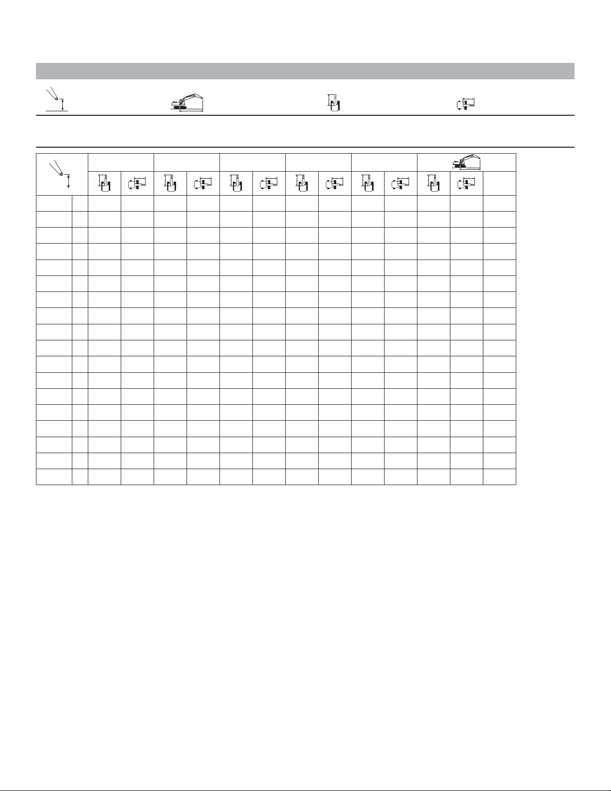
Super Long Reach Boom Lift Capacities
Load Point Height Load at Maximum Reach Load Radius Over Front Load Radius Over Side
Boom – 10.2 m (33'6") Counterweight – 6.75 mt (7.4 t) Bucket – None
Stick – 7.85 m (25'9") Super Long Reach Shoes – 700 mm (28") triple grouser
10.5 m/35.0 ft 12.0 m/40.0 ft 13.5 m/45.0 ft 15.0 m/50.0 ft 16.5 m/55.0 ft
12.0 m kg *1350 *1350 14.02
40.0 ft lb *3,350 *3,350 *2,950 *2,950 45.54
10.5 m kg *1300 *1300 15.00
35.0 ft lb *2,800 *2,800 48.88
9.0 m kg *2050 *2050 *1250 *1250 15.77
30.0 ft lb *3,950 *3,950 *2,750 *2,750 51.52
7.5 m kg *3000 2750 *2550 2250 *1250 *1250 16.37
25.0 ft lb *6,550 5,900 *5,150 4,750 *2,750 *2,750 53.56
6.0 m kg *3150 2700 *2950 2200 *1700 *1700 *1250 *1250 16.81
20.0 ft lb *6,900 5,700 *6,050 4,650 *2,850 *2,850 *2,750 *2,750 55.06
4.5 m kg *3500 3150 *3350 2550 *3300 2100 *2100 1700 *1300 *1300 17.10
15.0 ft lb *7,650 6,750 *7,350 5,500 *6,850 4,450 *3,850 3,650 *2,800 *2,800 56.08
3.0 m kg *4200 3700 *3850 3000 *3600 2450 3200 2000 *2350 1650 *1350 *1350 17.27
10.0 ft lb *9,050 7,900 *8,350 6,400 *7,850 5,200 6,850 4,300 *4,500 3,550 *2,900 *2,900 56.63
1.5 m kg *4650 3450 *4200 2800 3700 2300 3100 1950 *2550 1600 *1400 *1400 17.29
5.0 ft lb *10,100 7,400 *9,100 6,000 7,900 4,950 6,650 4,100 *4,800 3,400 *3,000 *3,000 56.74
Ground
kg 5100 3200 4200 2650 3550 2200 3050 1850 *2550 1550 *1450 1450 17.19
Line
lb 10,950 6,900 9,050 5,650 7,600 4,700 6,500 3,950 *4,800 3,300 *3,150 3,150 56.40
–1.5 m kg 4900 3000 4050 2500 3450 2100 2950 1800 *2400 1500 *1550 1450 16.95
–5.0 ft lb 10,550 6,450 8,750 5,350 7,400 4,500 6,300 3,800 *4,150 3,200 *3,400 3,150 55.60
–3.0 m kg 4750 2850 3950 2400 3350 2000 2900 1700 *1850 1500 *1650 1500 16.58
–10.0 ft lb 10,200 6,150 8,500 5,100 7,200 4,300 6,200 3,650 *3,650 3,250 54.34
–4.5 m kg 4650 2750 3850 2300 3300 1950 2850 1700 *1850 1550 16.05
–15.0 ft lb 9,950 5,950 8,300 4,950 7,100 4,200 6,150 3,600 *4,050 3,350 52.56
–6.0 m kg 4600 2700 3850 2250 3300 1950 2850 1700 *2050 1650 15.36
–20.0 ft lb 9,850 5,850 8,250 4,900 7,050 4,150 *4,950 3,650 *4,600 3,600 50.22
–7.5 m kg 4600 2700 3850 2300 3300 1950 *2400 1800 14.47
–25.0 ft lb 9,850 5,850 8,250 4,900 7,100 4,200 *5,350 4,000 47.23
–9.0 m kg 4650 2750 3900 2350 *2950 2050 13.36
–30.0 ft lb 10,000 5,950 8,400 5,050 *6,600 4,550 43.45
–10.5 m kg 4750 2850 *3900 2450 11.96
–35.0 ft lb 10,250 6,200 *8,900 5,550 38.66
–12.0 m kg *4900 3200 10.15
–40.0 ft lb *10,850 7,350 32.40
–13.5 m kg *5550 5500 7.10
m
ft
*Indicates that the load is limited by hydraulic lifting capacity rather than tipping load. The above loads are in compliance with hydraulic excavator lift capacity
standard ISO 10567:2007. They do not exceed 87% of hydraulic lifting capacity or 75% of tipping load. Weight of all lifting accessories must be deducted from the
above lifting capacities. Lifting capacities are based on the machine standing on a firm, uniform supporting surface. The use of a work tool attachment point to
handle/lift objects, could affect the machine lift performance.
Always refer to the appropriate Operation and Maintenance Manual for specific product information.
27
Page 28

329E Hydraulic Excavator Specications
Work Tool Offering Guide*
Boom Type HD Reach Boom Mass Boom
Stick Size R3.2 (10'6") R2.65 (8'8") M2.5 (8'2")
Hydraulic Hammer H120E s H120E s H120E s
Multi-Processor MP20 MP20 MP20
Mobile Scrap and Demolition Shear S320B S320B S320B
Compactor (Vibratory Plate) CVP110 CVP110 CVP110
Contractors’ Grapple G120B – G130B G120B – G130B G120B – G130B
Trash Grapple
Thumbs
Rippers
Rakes
Center-Lock Pin Grabber Coupler
Dedicated Quick Coupler
*Matches are dependent on excavator configurations. Consult your Cat dealer for proper work tool match.
**Pin-on only.
***Boom Mount.
H130E s H130E s H130E s
H140D s H140D s H140D s
MP30**
S325B** S325B S325B
S340B*** S340B*** S340B***
These work tools are available for the 329E.
Consult your Cat dealer for proper match.
28
Page 29
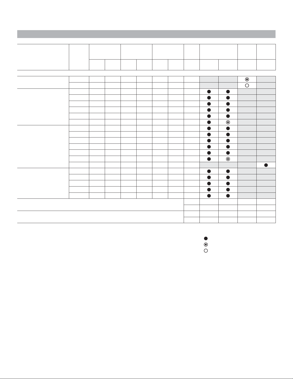
Bucket Specifications and Compatibility
Width Reach Boom (HD) Reach Boom
Linkage mm in (10'6") (8'8") (25'9") (8'2")
Without Quick Coupler
Ditch Cleaning (DC)
General Duty (GDC)
Heavy Duty (HD)
Severe Duty (SD)
A 1238 49 0.57 0.75 289 637 100%
A 770 30 0.69 0.90 377 830 100%
CB 600 24 0.63 0.83 724 1,595 100%
CB 750 30 0.86 1.13 810 1,785 100%
CB 900 36 1.09 1.43 907 1,998 100%
CB 1050 42 1.34 1.75 979 2,157 100%
CB 1200 48 1.58 2.07 1070 2,358 100%
CB 1350 54 1.83 2.40 1164 2,564 100%
CB 600 24 0.52 0.68 763 1,681 100%
CB 750 30 0.71 0.93 847 1,866 100%
CB 900 36 0.91 1.19 935 2,061 100%
CB 1050 42 1.12 1.46 1024 2,256 100%
CB 1200 48 1.33 1.74 1095 2,413 100%
CB 1350 54 1.54 2.02 1188 2,618 100%
DB 1500 60 1.88 2.46 1624 3,579 100%
CB 600 24 0.52 0.68 810 1,784 90%
CB 750 30 0.71 0.93 902 1,987 90%
CB 900 36 0.91 1.19 999 2,202 90%
CB 1050 42 1.12 1.46 1097 2,417 90%
CB 1200 48 1.33 1.74 1178 2,595 90%
Super
Long Mass
Capacity Weight Fill
R3.2 HD R2.65 HD 7.85 m M2.5
m yd kg lb %
Maximum load pin-on (payload + bucket) kg 4955 4485 1145 5725
lb 10,921 9,885 2,524 12,618
Maximum standard bucket width mm 1524 1524 – 1676
in 60 60 – 66
The above loads are in compliance with hydraulic excavator standard EN474, they do not exceed 87%
of hydraulic lifting capacity or 75% of tipping capacity over the side with front linkage fully extended
atground line with bucket curled. 1800 kg/m (3,000 lb/yd)
Capacity based on ISO 7451. 1200 kg/m (2,000 lb/yd)
Bucket weight with General Duty tips.
Caterpillar recommends using appropriate work tools to maximize the value customers receive from our products. Use of work tools, including buckets, which are
outside of Caterpillar’s recommendations or specifications for weight, dimensions, flows, pressures, etc. may result in less-than-optimal performance, including
but not limited to reductions in production, stability, reliability, and component durability. Improper use of a work tool resulting in sweeping, prying, twisting and/or
catching of heavy loads will reduce the life of the boom and stick.
Maximum Material Density:
2100 kg/m (3,500 lb/yd)
29
Page 30
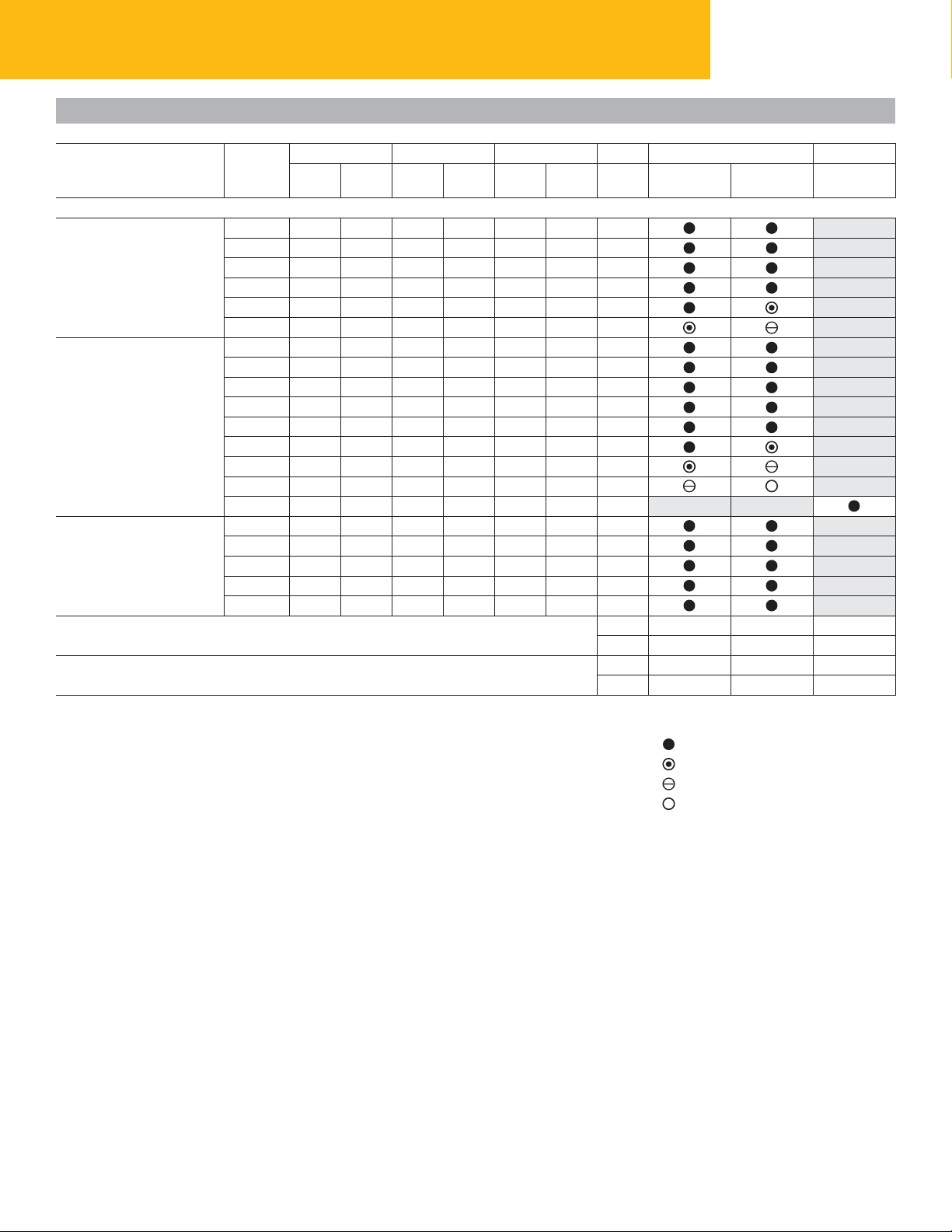
Bucket Specifications and Compatibility
329E Hydraulic Excavator Specications
With Center Lock Coupler
General Duty (GDC)
Heavy Duty (HD)
Severe Duty (SD)
Width
Linkage
CB 600 24 0.63 0.83 724 1,595 100%
CB 750 30 0.86 1.13 810 1,785 100%
CB 900 36 1.09 1.43 907 1,998 100%
CB 1050 42 1.34 1.75 979 2,157 100%
CB 1200 48 1.58 2.07 1070 2,358 100%
CB 1350 54 1.83 2.40 1164 2,564 100%
CB 600 24 0.52 0.68 763 1,681 100%
CB 750 30 0.71 0.93 847 1,866 100%
CB 900 36 0.91 1.19 935 2,061 100%
CB 1050 42 1.12 1.46 1024 2,256 100%
CB 1200 48 1.33 1.74 1095 2,413 100%
CB 1350 54 1.54 2.02 1188 2,618 100%
CB 1500 60 1.76 2.30 1285 2,831 100%
CB 1650 66 1.97 2.58 1357 2,990 100%
DB 1500 60 1.88 2.46 1624 3,579 100%
CB 600 24 0.52 0.68 810 1,784 90%
CB 750 30 0.71 0.93 902 1,987 90%
CB 900 36 0.91 1.19 999 2,202 90%
CB 1050 42 1.12 1.46 1097 2,417 90%
CB 1200 48 1.33 1.74 1178 2,595 90%
mm in
Maximum load with coupler (payload + bucket) kg 4450 3980 5167
Maximum standard bucket width with coupler mm 1676 1676 1676
Capacity Weight Fill
m yd kg lb %
Reach Boom (HD)
R3.2 HD R2.65 HD
(10'6") (8'8")
lb 9,809 8,773 11,388
in 66 66 66
Mass Boom
M2.5
(8'2")
The above loads are in compliance with hydraulic excavator standard EN474, they do not exceed 87%
of hydraulic lifting capacity or 75% of tipping capacity over the side with front linkage fully extended
atground line with bucket curled. 1800 kg/m (3,000 lb/yd)
Capacity based on ISO 7451. 1500 kg/m (2,500 lb/yd)
Bucket weight with General Duty tips. 1200 kg/m (2,000 lb/yd)
Caterpillar recommends using appropriate work tools to maximize the value customers receive from our products. Use of work tools, including buckets, which are
outside of Caterpillar’s recommendations or specifications for weight, dimensions, flows, pressures, etc. may result in less-than-optimal performance, including
but not limited to reductions in production, stability, reliability, and component durability. Improper use of a work tool resulting in sweeping, prying, twisting and/or
catching of heavy loads will reduce the life of the boom and stick.
Maximum Material Density:
2100 kg/m (3,500 lb/yd)
30
Page 31

Standard equipment may vary. Consult your Cat dealer for details.
329E Standard Equipment
ENGINE
C7.1 diesel engine
Biodiesel capable
Meets EPA Tier 4 (Interim) emission
standards
2300 m (7,500 ft) altitude capability
Electric priming pump
Automatic engine speed control
Standard, economy and high power modes
Two-speed travel
Side-by-side cooling system
Radial seal air lter
Primary lter with water separator and
Fuel differential indicator switch in fuel line
1×4 micron main lters
1×10 micron primary fuel line lter
HYDRAULIC SYSTEM
Regeneration circuit for boom and stick
Reverse swing dampening valve
Automatic swing parking brake
High-performance hydraulic return lter
Capability of installing HP stackable valve
Capability of installing additional auxiliary
Capability of installing boom lowering control
Capability of installing Cat Bio hydraulic oil
water separator indicator switch
and medium and QC valve
pump and circuit
device and stick lowering check valve
CAB
Pressurized operator station
with positive ltration
Mirror package
Sliding upper door window
(left-hand cab door)
Glass-breaking safety hammer
Removable lower windshield
with in cab storage bracket
Coat hook
Beverage holder
Literature holder
Radio with MP3 auxiliary audio port
Two stereo speakers
Storage shelf suitable for lunch or toolbox
Color LCD display with warning, lter/ uid
change, and working hour information
Adjustable armrest
Height adjustable joystick consoles
Neutral lever (lock out) for all controls
Travel control pedals
with removable hand levers
Capability of installing two additional pedals
Two power outlets, 10 amp (total)
Laminated glass front upper window
and tempered other windows
UNDERCARRIAGE
Grease Lubricated Track GLT2, resin seal
Towing eye on base frame
ELECTRICAL
80 amp alternator
Circuit breaker
Capability to electrically connect a beacon
LIGHTS
Boom light with time delay
Cab lights with time delay
Exterior lights integrated into storage box
SECURITY
Cat one key security system
Door locks
Cap locks on fuel and hydraulic tanks
Lockable external tool/storage box
Signaling/warning horn
Secondary engine shutoff switch
Openable skylight for emergency exit
Rearview camera ready
31
Page 32

329E Optional Equipment
Optional equipment may vary. Consult your Cat dealer for details.
ENGINE
Electric refueling pump with auto shut off
Starting kit, cold weather, –32° C (–26° F)
Jump start receptacle
Quick drains, engine and hydraulic oil
HYDRAULIC SYSTEM
Control pattern quick-changer, two way
Additional circuit
Boom and stick lines
High-pressure line
Medium-pressure line
Cat quick coupler line – high- and
medium-pressure capable
Quick coupler for high pressure
Tool control system
Tool 20, Electronic Control device,
(common), 1/2P, common circuit
Tool 21, Electronic Control device, 1/2P,
one-way circuit
Tool 25, Electronic Control device, 1P,
two-way circuit
CAB
Cab hatch emergency exit
Seat, high-back air suspension
with heater and cooling
Seat, high-back air suspension with heater
Seat, high-back mechanical suspension
Sunscreen
Windshield wiper, lower with washer
AM/FM radio
Air pre- lter
Travel alarm
Left foot switch
Left pedal
Straight travel pedal
UNDERCARRIAGE
600 mm (24") double grouser shoes
700 mm (28") triple grouser shoes
800 mm (32") triple grouser shoes
900 mm (35") triple grouser shoes
Guard, full length for long FG undercarriage
Guard, heavy-duty bottom
Center track guiding guard
Segmented (3 piece) track guiding guard
COUNTERWEIGHT
5.8 mt (6.3 t)
6.75 mt (7.4 t)
FRONT LINKAGE
Bucket linkage, CB2 family
without lifting eye
Bucket linkage, CB2 family with lifting eye
Mass 5.55 m (18'3") boom
Mass 2.5DB m (8'2") stick
SLR 10.2 m (33'6") boom
SLR 7.85 m (25'9") stick
LIGHTS
Working lights, cab mounted with time delay
HID lights, cab mounted with time delay
Halogen boom lights
HID boom lights
SECURITY
FOGS, bolt-on
Guard, cab front, mesh
Guard, vandalism
Cat MSS (anti-theft device)
Rearview camera
TECHNOLOGY
Cat Grade Control Depth and Slope
Product Link
32
Page 33

Notes
33
Page 34

Notes
34
Page 35

35
Page 36

329E Hydraulic Excavator
For more complete information on Cat products, dealer services, and industry solutions,
visit us on the web at www.cat.com
© 2011 Caterpillar Inc.
All rights reserved
Materials and specications are subject to change without notice. Featured machines
in photos may include additional equipment. See your Cat dealer for available options.
CAT, CATERPILLAR, SAFETY.CAT.COM, their respective logos, “Caterpillar Yellow”
and the “Power Edge” trade dress, as well as corporate and product identity used herein,
are trademarks of Caterpillar and may not be used without permission.
20
AEHQ6293 (07-2011)
(Americas)
 Loading...