

Page 1

Cerrar SIS
Page 1 of 3
325D L Excavator A3R00001-UP (MACHINE) POWERED BY C7 Engine(SEBP4513 - ...
16/4/2019
https://127.0.0.1/sisweb/sisweb/techdoc/techdoc_print_page.jsp?returnurl=/sisweb/sisweb/...
Pantalla anterior
Producto: EXCAVATOR
Modelo: 325D L EXCAVATOR A3R
Configuración: 325D L Excavator A3R00001-UP (MACHINE) POWERED BY C7 Engine
Especificaciones
C7 Engines for Caterpillar Built Machines
Número de medio -SENR9938-30 Fecha de publicación -01/05/2014 Fecha de actualización -06/06/2014
i04371168
Connecting Rod
SMCS - 1218
Page 2
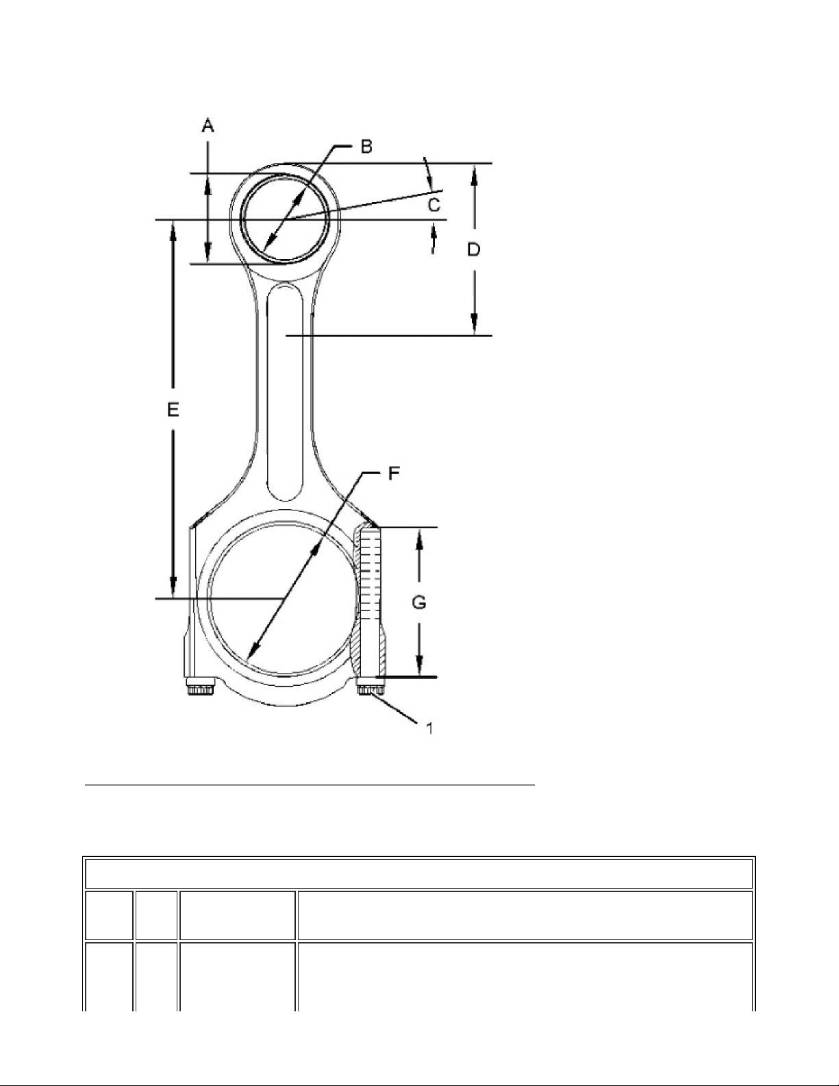
Illustration 1 g01405580
Page 2 of 3
325D L Excavator A3R00001-UP (MACHINE) POWERED BY C7 Engine(SEBP4513 - ...
16/4/2019
https://127.0.0.1/sisweb/sisweb/techdoc/techdoc_print_page.jsp?returnurl=/sisweb/sisweb/...
Table 1
Specification for 213-3193 Connecting Rod
Item Qty
A 1 211-0595
Part Specification Description
Handle the fractured connecting rod with care. Use a soft jawed
Connecting
vise in order to hold the connecting rod while loosening the
Rod
Page 3

connecting rod cap bolts. Use a soft faced hammer in order to tap
the connecting rod cap, if necessary.
Page 3 of 3
325D L Excavator A3R00001-UP (MACHINE) POWERED BY C7 Engine(SEBP4513 - ...
16/4/2019
https://127.0.0.1/sisweb/sisweb/techdoc/techdoc_print_page.jsp?returnurl=/sisweb/sisweb/...
Bore for piston pin bearing is
43.191 ± 0.013 mm (1.7004 ± 0.0005 inch).
B 1
2W-0027
Bearing
C - -
D - -
E - -
F - -
G 2
229-6266 Bolt Length of the bolt is
After installation, bore in the bearing is
40.028 ± 0.008 mm (1.5759 ± 0.0003 inch).
The bearing joint for the piston pin bearing must be positioned to
the angle above the centerline on either side is 12 ± 5 degrees.
Before installation of the piston pin bearing, connecting rod small
end must be heated from
175 to 260 °C (347 to 500 °F).
Distance for heating the connecting rod for the installation of the
piston pin bearing is
75 ± 5 mm (3.0 ± 0.2 inch).
Distance between the center of the connecting rod bores is
200 mm (7.9 inch).
Bore in the connecting rod for the bearing for the crankshaft
connecting rod journal is
75.000 ± 0.013 mm (2.9527 ± 0.0005 inch).
65.0 ± 0.5 mm (2.56 ± 0.02 inch).
- - -
Copyright 1993 - 2019 Caterpillar Inc.
Todos los derechos reservados.
Red privada para licenciados del SIS.
Use the following procedure to tighten the connecting rod bolts:
1. Before installing the rod cap, clean the mating surfaces of the
connecting rod with compressed air or a steel brush.
2. Lubricate the seating faces of the cap with 4C-5599 Anti-Seize
Compound or clean engine oil.
2. Install new bolts (1) and torque each bolt to
70 ± 5 N·m (50 ± 4 lb ft).
3. Place an index mark on each connecting rod cap bolt and tighten
each bolt for an additional turn of 120 ± 5 degrees.
Tue Apr 16 15:26:55 EST 2019
 Loading...