

Page 1
®
®
Engine
Engine Model Cat®C7 with
ACERT™ Technology
Net Flywheel Power 140 kW 188 hp
Weights
Operating Weight – Minimum 23 860 kg 52,602 lb
• Base Machine, Reach Boom, R2.5CB1 (8 ft 2 in) Stick,
0.63 m3(0.82 yd3) Bucket, 600 mm (24 in) Shoes.
Operating Weight 24 790 kg 54,660 lb
• Base Machine, Reach Boom, R2.95CB1 (9 ft 8 in) Stick,
1.1 m3(1.44 yd3) Bucket, 800 mm (32 in) Shoes.
Operating Weight – Maximum 26 250 kg 57,871 lb
• Base Machine, Mass Boom, M2.5DB (8 ft 2 in) Stick,
2.34 m3(3.06 yd3) Bucket, 800 mm (32 in) Shoes.
NOTE – The above configurations do not include any
optional attachments.
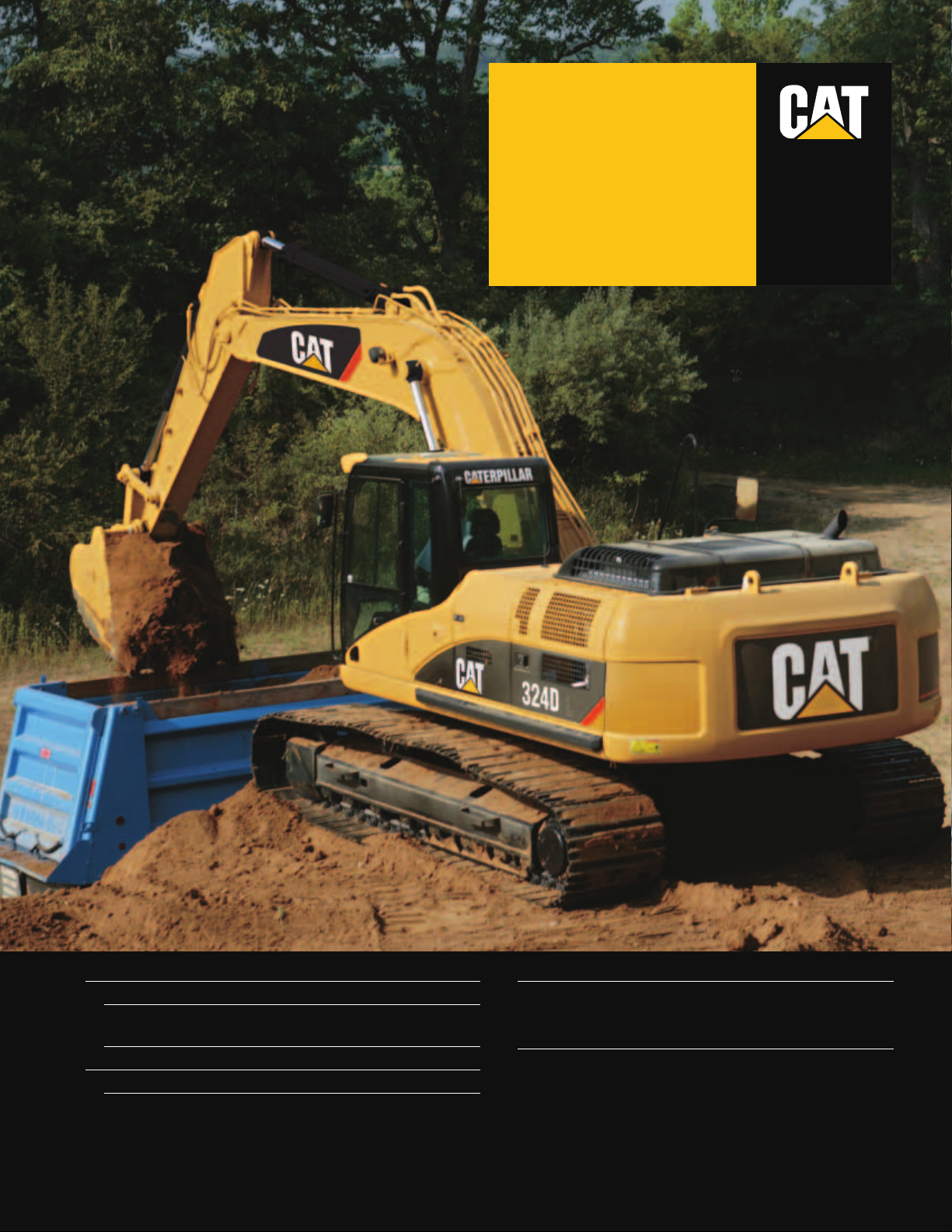
324D L
Hydraulic Excavator
Page 2
2
324D L Hydraulic Excavator
The D Series incorporates innovations for improved performance and versatility.
Service and Maintenance
Fast, easy service has been designed in
with extended service intervals,
advanced filtration, convenient filter
access and user-friendly electronic
diagnostics for increased productivity
and reduced maintenance costs. pg. 12
Versatility
Caterpillar offers a wide variety of
factory-installed attachments that
enhance performance and job site
management. pg. 11
Operator Comfort
Provides maximum space, wider
visibility and easy access to switches.
The monitor is a full-color graphical
display that allows the operator to
understand the machine information
easily. Overall, the new cab provides
a comfortable environment for the
operator. pg. 6
✔
Hydraulics
The hydraulic system has been designed
to provide reliability and outstanding
controllability. An optional Tool
Control System provides enhanced
flexibility. pg. 5
C7 with ACERT™ Technology
ACERT™ Technology works at the
point of combustion to optimize engine
performance and provide low exhaust
emissions to meet U.S. EPA Tier 3
emission regulations, with exceptional
performance capabilities and proven
reliability. pg. 4
✔
Page 3
✔ New Feature
3
Complete Customer Support
Your Cat®dealer offers a wide range
of services that can be set up under a
customer support agreement when you
purchase your equipment. The dealer will
help you choose a plan that can cover
everything from machine configuration
to eventual replacement. pg. 13
Work Tools – Attachments
A variety of work tools, including
buckets, couplers, hammers, and shears
are available through Cat Work Tools.
pg. 10
✔
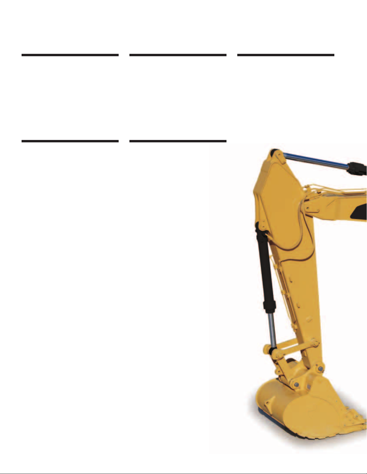
Booms, Sticks and Bucket Linkages
Three lengths of booms and five sticks
are available, offering a range of
configurations suitable for a wide
variety of application conditions.
The bucket linkage pins have been
enlarged to improve reliability and
durability. All Booms and Sticks
are stress relieved. pg. 9
Structures
Caterpillar®design and manufacturing
techniques assure outstanding durability
and service life from these important
components. pg. 8
Page 4
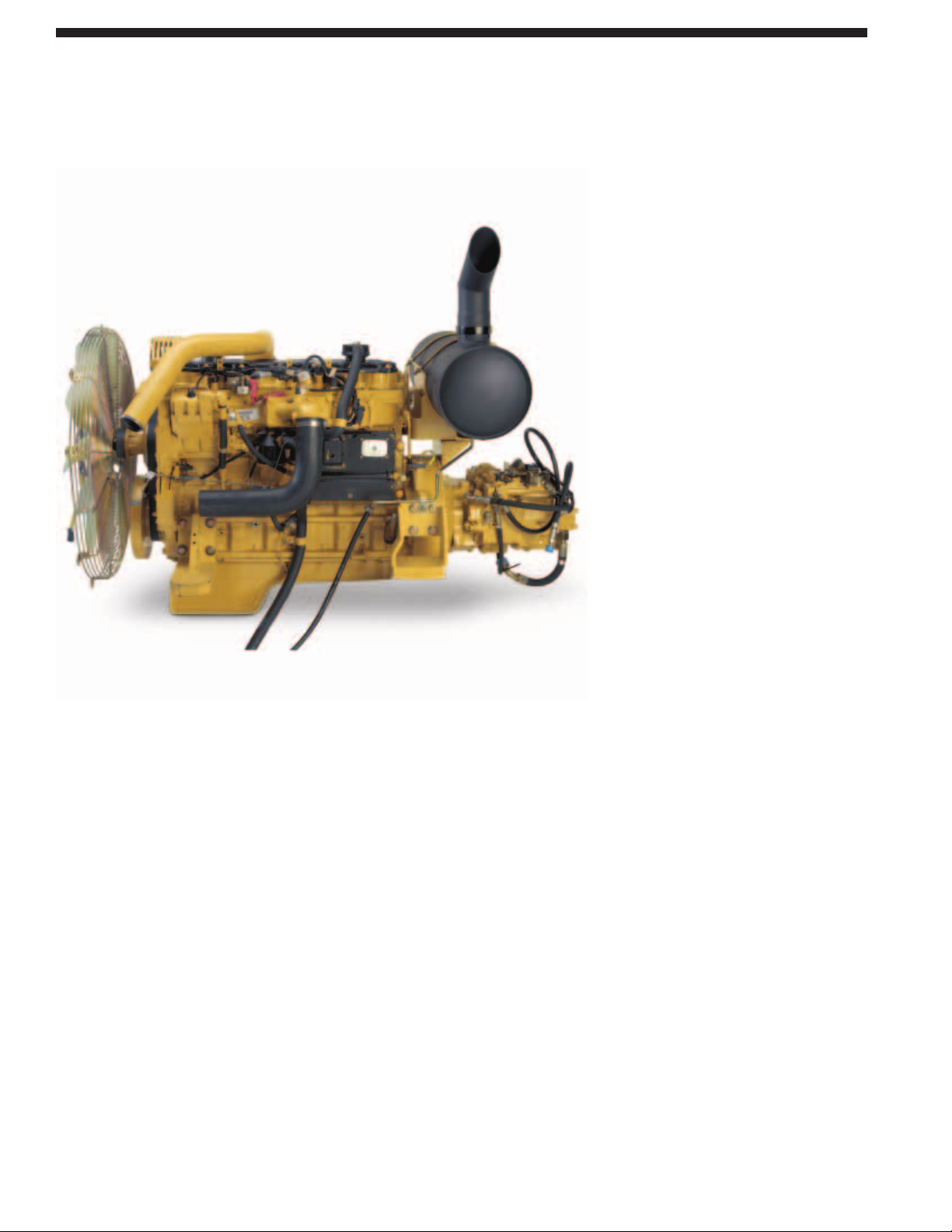
Cat C7. The Cat C7 with ACERT™
Technology introduces a series of
evolutionary, incremental improvements
that provide breakthrough engine
technology. The building blocks of
ACERT Technology are fuel delivery,
air management and electronic control.
ACERT Technology optimizes engine
performance while meeting U.S. EPA
Tier 3 emission regulations.
Performance. The 324D L, equipped
with the C7 engine with ACERT™
Technology, provides 12% more
horsepower as compared to the
3126B ATAAC HEUI in the 325C L.
Automatic Engine Speed Control.
The two-stage, one-touch control
maximizes fuel efficiency and reduces
sound levels.
ADEM™ A4 Engine Controller.
The ADEM A4 electronic control
module manages fuel delivery to get the
best performance per liter of fuel used.
The engine management system provides
flexible fuel mapping, allowing the
engine to respond quickly to varying
application needs. It tracks engine and
machine conditions while keeping the
engine operating at peak efficiency.
Electronic Control Module.
The Electronic Control Module (ECM)
works as the “brain” of the engine’s
control system, responding quickly
to operating variables to maximize
engine efficiency. Fully integrated with
sensors in the engine’s fuel, air, coolant,
and exhaust systems, the ECM stores
and relays information on conditions
such as rpm, fuel consumption, and
diagnostic information.
Fuel Delivery. The Cat C7 features
electronic controls that govern the
fuel injection system. Multiple injection
fuel delivery involves a high degree
of precision. Precisely shaping the
combustion cycle lowers combustion
chamber temperatures, generating
fewer emissions and optimizing fuel
combustion. This translates into more
work output for your fuel cost.
Cooling System. The cooling fan
is directly driven from the engine.
An electrically controlled viscous clutch
fan is available as an attachment to
reduce fan noise. The optimum fan
speed is calculated based on the target
engine speed, coolant temperature,
hydraulic oil temperature and actual
fan speed. The Cat C7 delivered a
completely new layout that separates
the cooling system from the engine
compartment.
Air Cleaner. The radial seal air filter
features a double-layered filter core
for more efficient filtration and is
located in a compartment behind
the cab. A warning is displayed on
the monitor when dust accumulates
above a preset level.
Noise Reduction Technologies.
The engine mounts are rubber-isolating
mounts matched with the engine package.
Further noise reduction has been achieved
through design changes to the isolated
top cover, oil pan, multiple injection
strategy, insulated timing cover, sculpted
crankcase and gear train refinements.
4
C7 with ACERT™ Technology
The Cat®C7 gives the 324D exceptional power and fuel efficiency unmatched in the industry
for consistently high performance in all applications.
Page 5
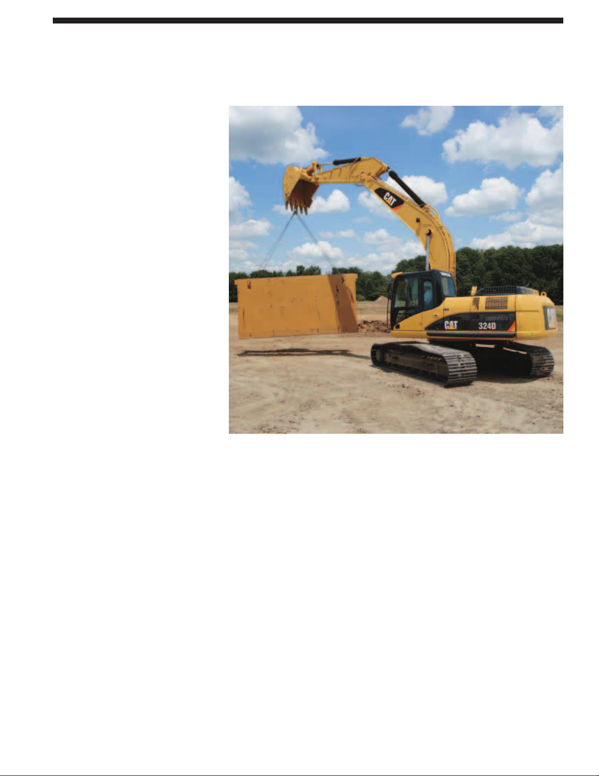
Component Layout. The 324D hydraulic
system and component locations have
been designed to provide a high level
of system efficiency. The main pumps,
control valves and hydraulic tank are
located close together to allow for shorter
tubes and lines between components
that reduce friction loss and pressure
drops in the lines. The layout further
provides greater operator comfort by
placing the radiator on the cab side of
the upper structure. This allows incoming
air to enter the engine compartment
from the operator side and hot air and
corresponding engine sound to exit on
the opposite side away from the operator.
This reduces engine compartment
heat and sound being transmitted
to the operator.
Pilot System. The pilot pump is
independent from the main pumps
and controls the front linkage, swing
and travel operations.
Hydraulic Cross Sensing System.
The hydraulic cross sensing system
utilizes each of two hydraulic pumps
to 100 percent of engine power, under
all operating conditions. This improves
productivity with faster implement
speeds and quicker, stronger pivot turns.
Boom and Stick Regeneration Circuit.
Boom and stick regeneration circuit
saves energy during boom-down and
stick-in operation which increases
efficiency, reduces cycle times and
pressure loss for higher productivity,
lower operating costs and increased
fuel efficiency.
Auxiliary Hydraulic Valve. The auxiliary
valve is standard on the 324D. Control
Circuits are available as attachments,
allowing for operation of high and
medium pressure tools such as shears,
grapples, hammers, pulverizers, multiprocessors and vibratory plate compactors.
Hydraulic Cylinder Snubbers.
Snubbers are located at the rod-end
of the boom cylinders and both ends
of the stick cylinders to cushion shocks
while reducing sound levels and
extending component life.
5
Hydraulics
Cat®hydraulics deliver power and precise control to keep material moving.
Page 6
6
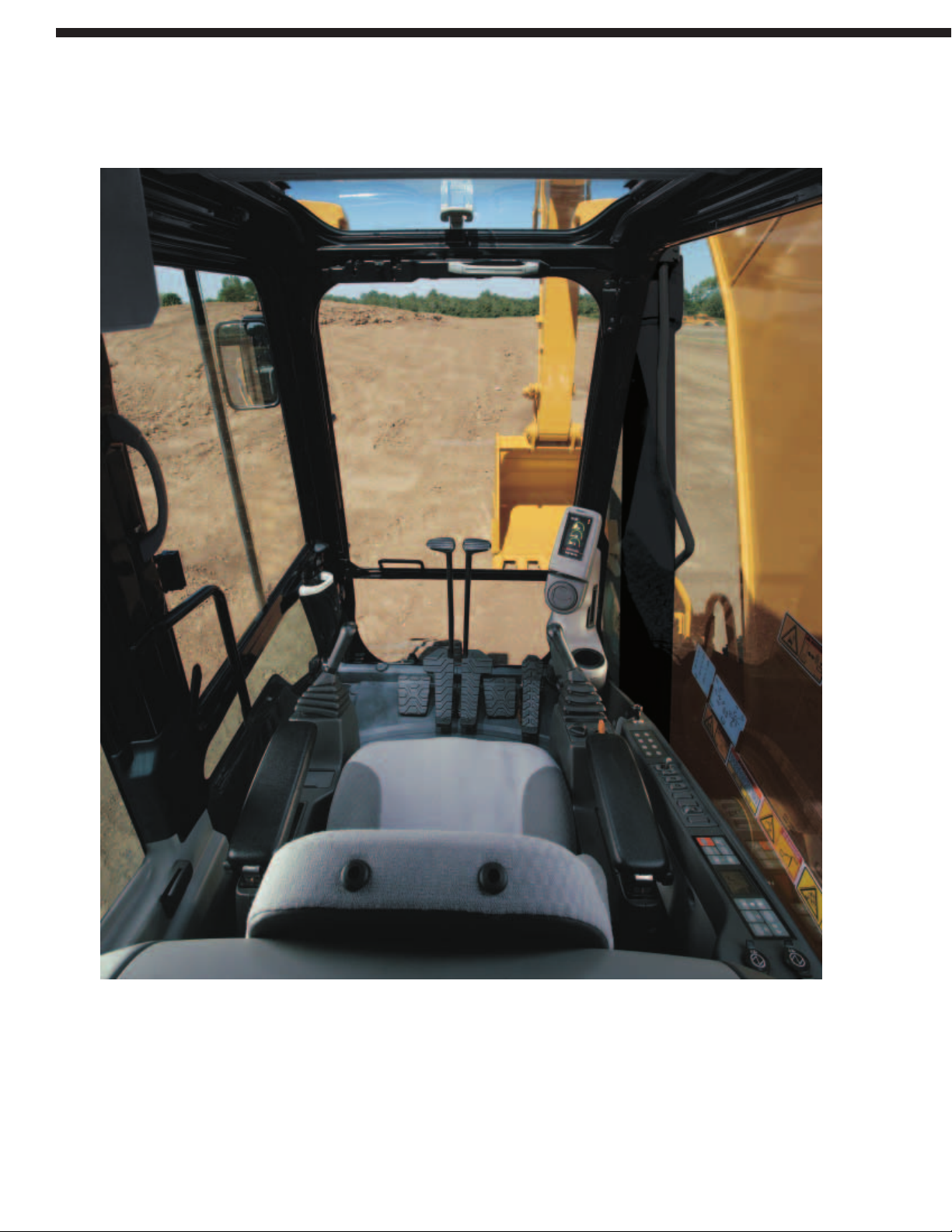
Designed for comfort, simple and easy operation, the 324D allows the operator to focus
on production.
Operator Comfort
Page 7
Operator Station. The workstation is
spacious, quiet and comfortable, assuring
high productivity during a long work
day. The air conditioner and attachment
switches are conveniently located on the
right-hand wall, and the key switch and
throttle dial are on the right-hand console.
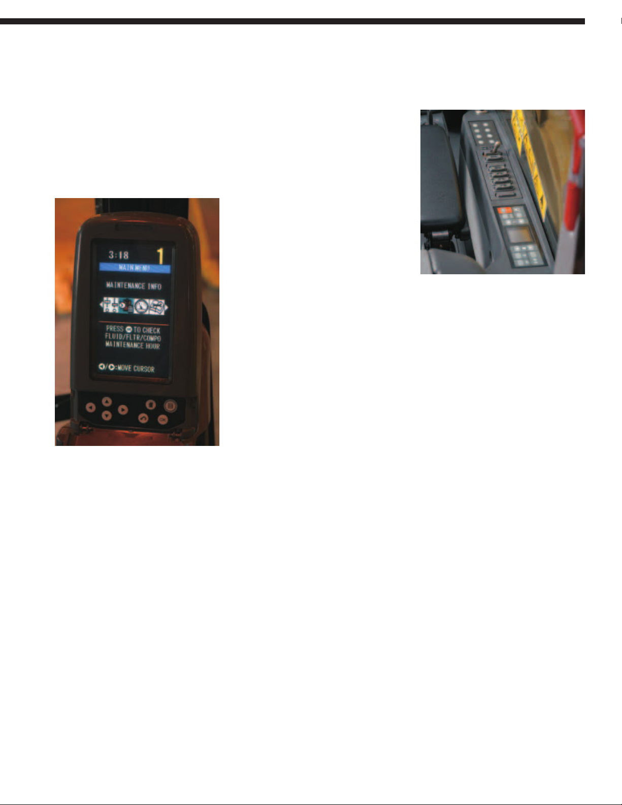
Monitor. The monitor is a full color
400x234 pixels Liquid Crystal Display
(LCD) graphic display. The monitor
angle can be adjusted to minimize sun
glare and has the capability of displaying
information in twenty-seven different
languages.
Pre-Start Check. Prior to starting the
machine, the system will check for low
fluid levels for the engine oil, hydraulic
oil and engine coolant and warn the
operator through the monitor in the
event display area.
Gauge Display. Three analog gauges,
fuel level, hydraulic oil temperature
and coolant temperature, are displayed
in this area.
Event Display. Machine information
is displayed in this area with the icon
and language.
Multi-information Display. This area
is reserved for displaying various
information which is convenient
for the operator. The “CAT” logo
is displayed when no information
is available to be displayed.
Standard Cab Equipment. To enhance
operator comfort and productivity, the
cab includes a lighter, drink holder, coat
hook, service meter, literature holder,
magazine rack and storage compartment.
Seat. A new optional air suspension seat
is available in the 324D. The standard
and optional seats provide a variety of
adjustments to suit the operator’s size
and weight including fore/aft, height and
weight. Wide adjustable armrests and a
retractable seat belt are also included.
Joystick Control. Joystick controls have
low lever effort and are designed to
match the operator’s natural wrist and
arm position. The operator can operate
joystick controls with an arm on the
armrest and the horizontal and vertical
strokes have been designed to reduce
operator fatigue.
Hydraulic Activation Control Lever.
For added safety, this lever must be
in the operate position to activate the
machine control functions.
Automatic Climate Control.
Fully automatic climate control adjusts
temperature and flow, and determines
which air outlet is best in each situation
with a touch of a button.
Console. Redesigned consoles feature
a simple, functional design to reduce
operator fatigue, ease of switch operation
and excellent visibility. Both consoles
have attached armrests with height
adjustments.
Cab Exterior. The exterior design uses
thick steel tubing along the bottom
perimeter of the cab, improving the
resistance of fatigue and vibration.
This design allows the FOGS to be
bolted directly to the cab, at the factory
or as an attachment later, enabling the
machine to meet specifications and
job site requirements.
Cab Mounts. The cab shell is attached
to the frame with viscous rubber cab
mounts, which dampen vibrations
and sound levels while enhancing
operator comfort.
Windows. All glass is affixed directly
to the cab for excellent visibility
eliminating window frames. The upper
front windshield opens, closes and
stores on the roof above the operator
with a one-touch action release system.
Wipers. Pillar-mounted wipers increase
the operator’s viewing area and offer
continuous and intermittent modes.
Skylight. An enlarged skylight with
sunshade provides excellent visibility
and ventilation.
7
Page 8
Robotic Welding. Up to 95% of the
structural welds on a Caterpillar
®
Excavator are completed by robots.
Robotic welds achieve over three times
the penetration of manual welds.
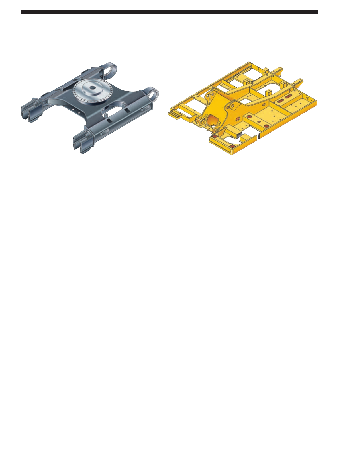
Carbody Design and Track Roller
Frames. X-shaped, box-section carbody
provides excellent resistance to torsion
bending. Robot-welded track roller
frames are press-formed, pentagonal
units to deliver exceptional strength
and service life.
Main Frame. Rugged main frame
is designed for maximum durability
and efficient use of materials.
Undercarriage. Durable Cat
®
undercarriage absorbs stresses and
provides excellent stability.
Swing Bearing. The swing bearing
utilizes cross roller bearings versus
the traditional ball bearing design.
The cross roller bearing design allows
for more surface contact to absorb the
stresses that are a result of the high
swing torque that Cat offers. It provides
exceptional machine stability and
reduces machine pitching during
boom down operation.
Rollers and Idlers. Sealed and lubricated
track rollers, carrier rollers, and idlers
provide excellent service life, to keep
the machine in the field longer.
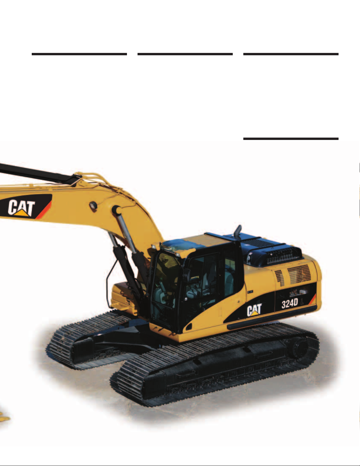
Long Undercarriage. The long (L)
undercarriage maximizes stability
and lift capacity. This long, wide,
and sturdy undercarriage offers
a very stable work platform.
8
Structures
324D structural components and undercarriage are the backbone
of the machine’s durability.
Page 9
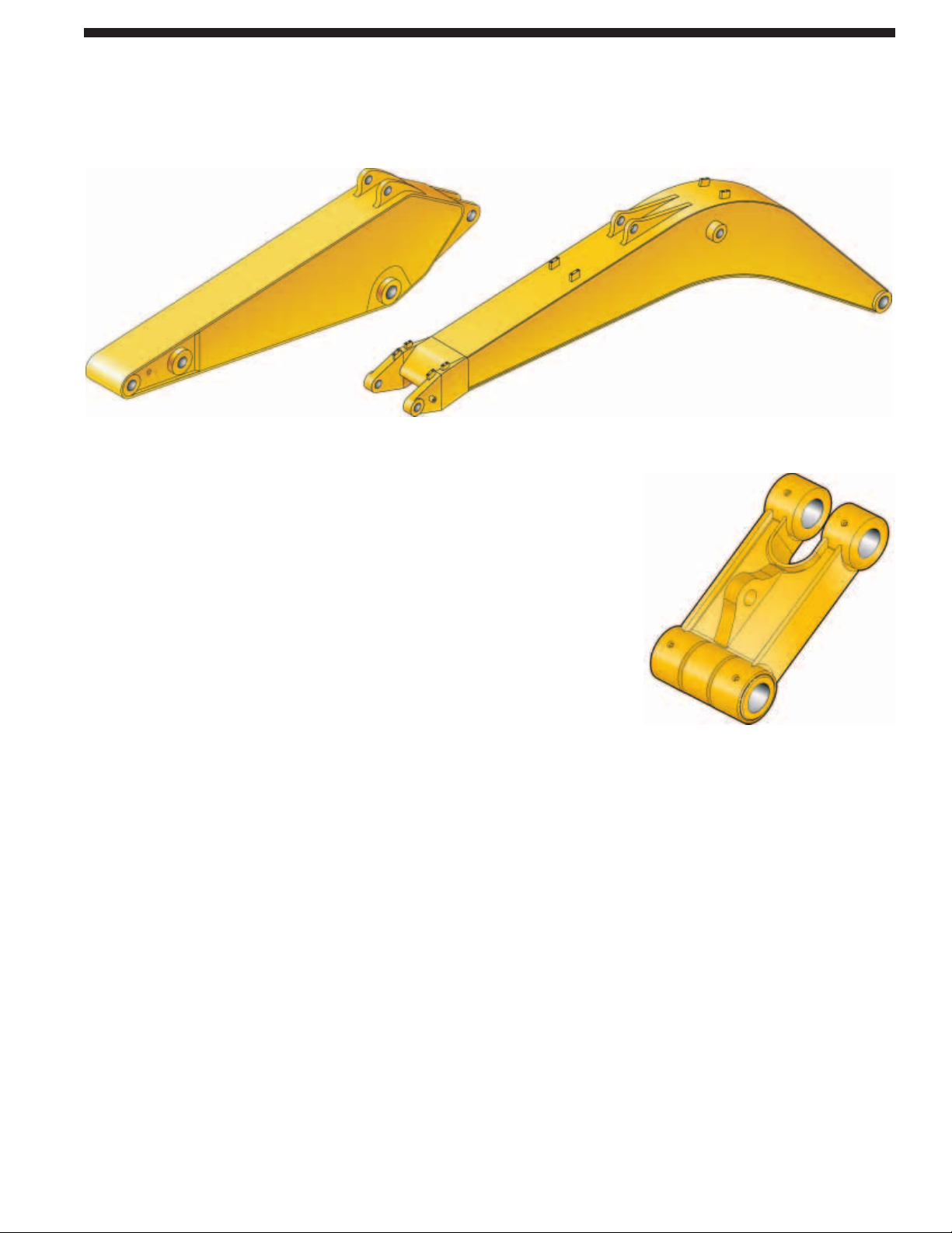
Reach Boom. The reach boom features
an optimum design that maximizes
digging envelopes with three stick
choices:
R3.6B and R2.95CB Sticks. These sticks
have enough capacity for excellent
reach and depth in trenching and
general construction applications.
R2.5CB Stick. This stick has been
designed with enough reach and depth
to match a large-capacity bucket and
higher stick digging forces than the
longer reach sticks.
Mass Excavation Boom. The mass
excavation boom maximizes productivity.
The mass version offers significantly
higher digging forces and allows use
of larger buckets.
M2.5DB. The DB Stick uses a D-family
bucket and was designed for high volume
earth moving, powerful digging force
and a large capacity bucket. Combined
with a Mass boom, this stick delivers
outstanding productivity.
Super Long Reach. This configuration
offers reaches to over 8.3 m (60 feet).
It is well suited for ditch cleaning
applications.
Linkage Pins. The bucket linkage pins
have been enlarged to improve reliability
and durability. All the pins in the front
linkages have thick chrome plating,
giving them high wear and corrosion
resistance.
Bucket Linkage. The power link
improves durability, increases machinelifting capability in key lifting positions
and with the integrated lift-eye it is
easier to use than compared to the
previous power link.
9
Booms, Sticks and Bucket Linkages
Built for performance and long service life, Caterpillar®booms and sticks are large, welded,
box-section structures with thick, multi-plate fabrications in high stress areas.
Page 10
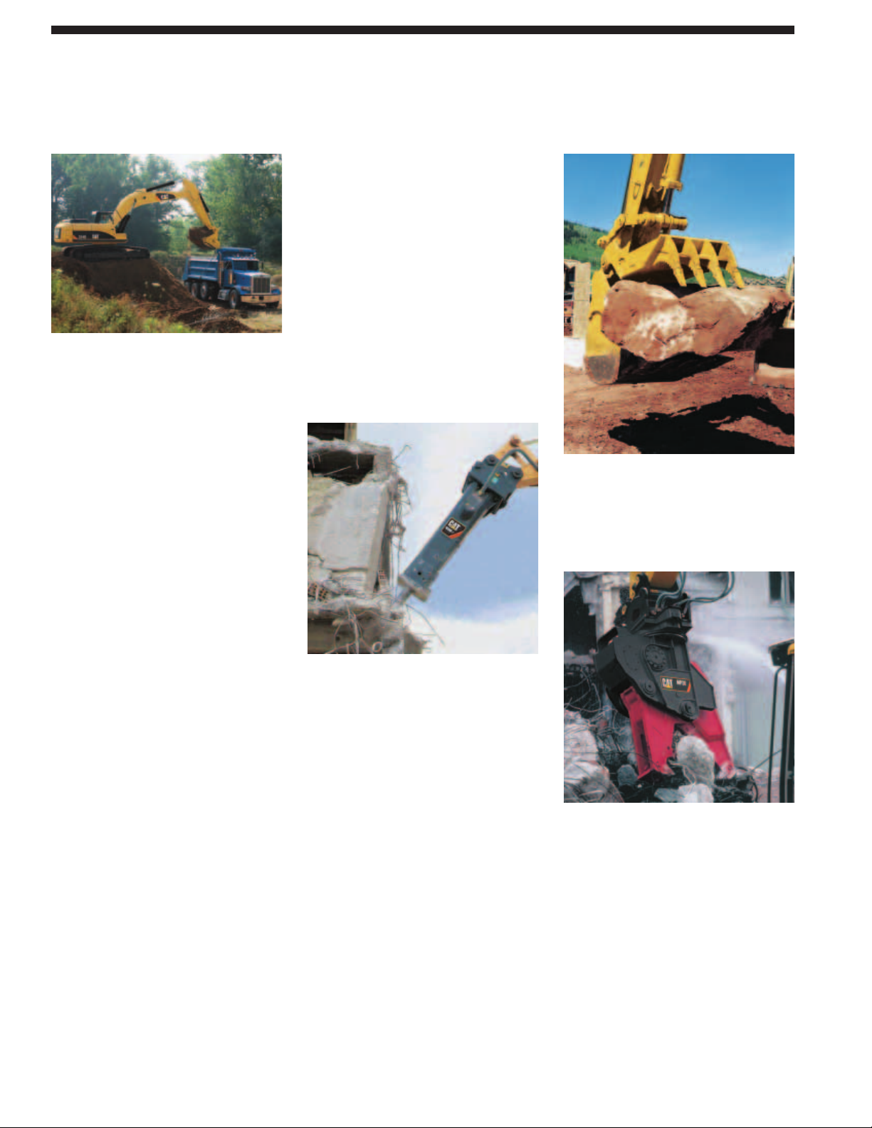
Heavy Duty Buckets. Heavy-duty (HD)
buckets are used for a wide range
of moderately abrasive applications
such as mixed dirt, clay and rock.
HD buckets have best loading and
dumping characteristics and will empty
easier in cohesive material. More robust
construction than the GP buckets.
General Purpose Capacity (GP-C)
Buckets. General Purpose Capacity
Buckets are best for digging in soft
to hard ground with low to moderately
abrasive materials.
Heavy-Duty Power (HDP) Buckets.
For use in moderately abrasive
applications where breakout force
and cycle times are critical. Maximizes
tip force and improves cycle times in
most materials.
Heavy Duty Rock Buckets. Heavy duty
rock for aggressive bucket loading in
highly abrasive application such as shot
rock and granite. Features include:
• Thickest wear plates to extend the
life of bucket in severe applications
• Side wear plated extend further up
the side of the bucket for maximum
protection in rocky soils
• Buckets accept sidebar protectors for
best sidebar protection, or sidecutters
for best fill characteristics and
bucket wear protection
Ditch Cleaning (DC) Buckets.
These wide shallow buckets are best
for bank forming, ditch cleaning,
and finishing.
Caterpillar Ground Engaging Tools
(GET). All bucket in the CB/DB Family
utilize the Caterpillar K Series
®
GET.
This GET system uses a vertical retainer
that is easier to remove and install than
the Cat J Series pin. The tip shapes
are more aggressive and offer better
penetration than the previous generation
of tips. There are also a variety of side
cutters and sidebar protectors to match
operating conditions.
Hammer
Cat Hydraulic Hammers are precisely
matched to Cat machines for optimum
performance in a wide variety of
demolition and construction applications.
Thumb
Cat thumbs multiply the capabilities
of your excavator. This Highly versatile
tool works in conjunction with the
bucket to transform an excavator into
a versatile material-handling machine.
Multi-processor
Multi-processors do the work of many
types of demolition tools by use of
interchangeable jaw sets. Changing jaws
allows a single unit to crush, pulverize
and perform a variety of specialized
cutting tasks, such as cutting steel
rebar and tanks.
10
Work Tools – Attachments
The 324D has an extensive selection of work tools to optimize machine performance.
Page 11
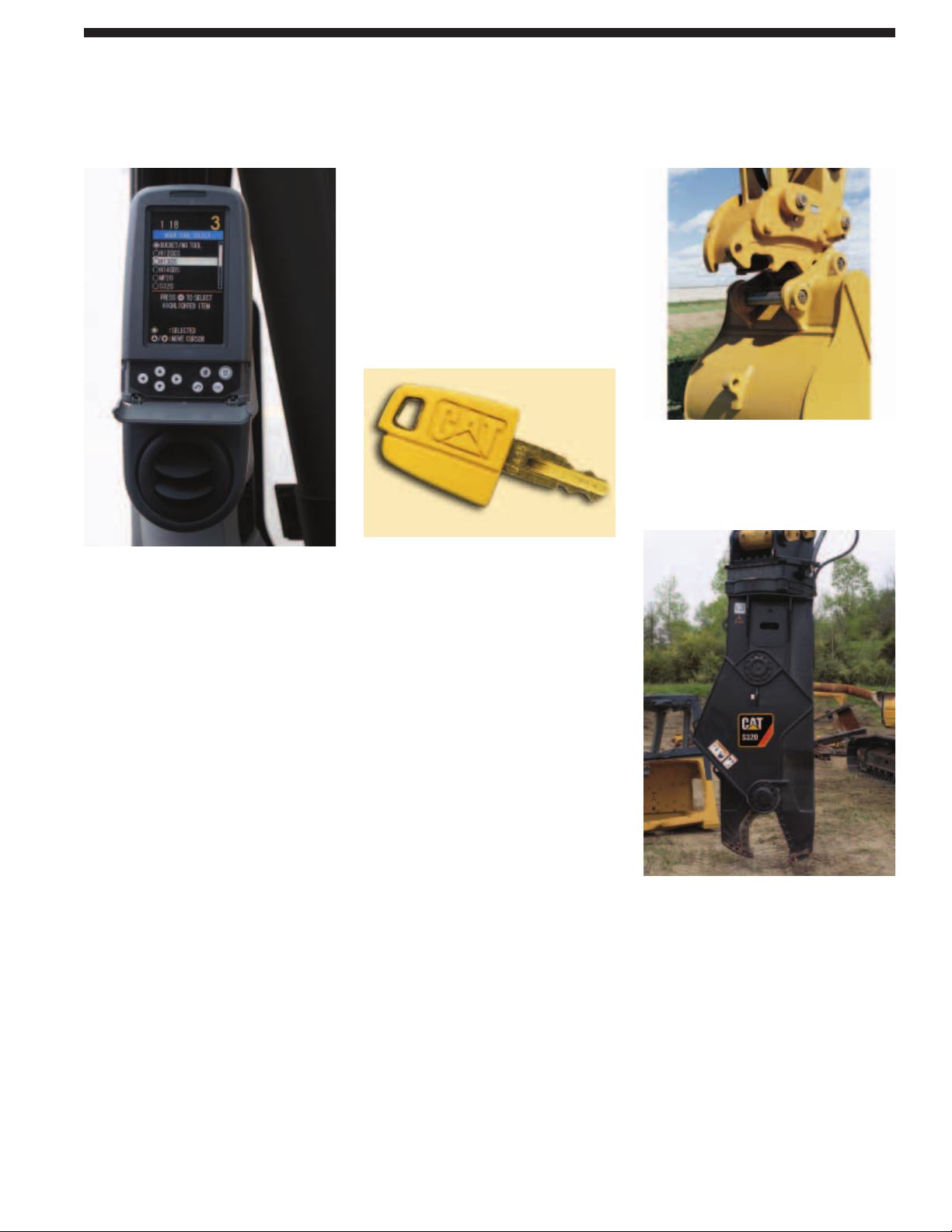
Tool Control System. This system offers
the most flexibility and versatility of the
auxiliary options offered. This system
is available in two configurations, as a
stand-alone system or with a medium
pressure circuit and third pump.
This system is capable of running
either one-way or two-way tools
and one one-pump or two pump tools.
The additional of the medium pressure
circuit allows use of tools that rotate
such as grapples, shears or multiprocessors. Up to 10 different tool
settings can be pre-programmed and
selected through the monitor.
Auxiliary Hydraulics Options. There are
four different options that can be factory
installed to meet the various demands for
hydra-mechanical tools. Single-Function,
Double-Function, Tool Control System
without Medium Pressure and Tool
Control System with Medium Pressure
are available as a factory installed option.
Single-Function Auxiliary Hydraulics.
This circuit utilizes one-way flow
action with two pumps and can run
tools such as hammers and vibratory
plate compactors.
Double-Function Auxiliary Hydraulics.
This circuit utilizes two-way flow and
one pump and is capable of running
tools such as a thumb, tilt-bucket or
non-rotating grapples or shears.
Machine Security. An optional Machine
Security System is available from the
factory on the 324D L. This system
controls when the machine can be
operated and utilizes specific keys
to prevent unauthorized machine use,
a significant theft deterrent.
Product Link. The machine is pre-wired
to accept Product Link systems to be
installed in the field. Product Link is
also available as a factory installed
attachment. Product Link can assist
with Fleet Management that will keep
track of hours, location, security and
product health.
Pin Grabber Plus Hydraulic Pin Grabber
Increases versatility of the excavator
by allowing the machine to pick up a
wide variety of work tools without
leaving the cab.
360 Scrap Shear
Caterpillar Scrap Shears feature 360°
rotation and a high force-to-weight
ratio. Used for demolishing steel
structures, and preparing bulk scrap
(such as cars, farm machinery and
railroad cars) for further processing.
11
Versatility
A wide variety of optional factory-installed attachments are available to enhance
performance and improve job site management.
Page 12
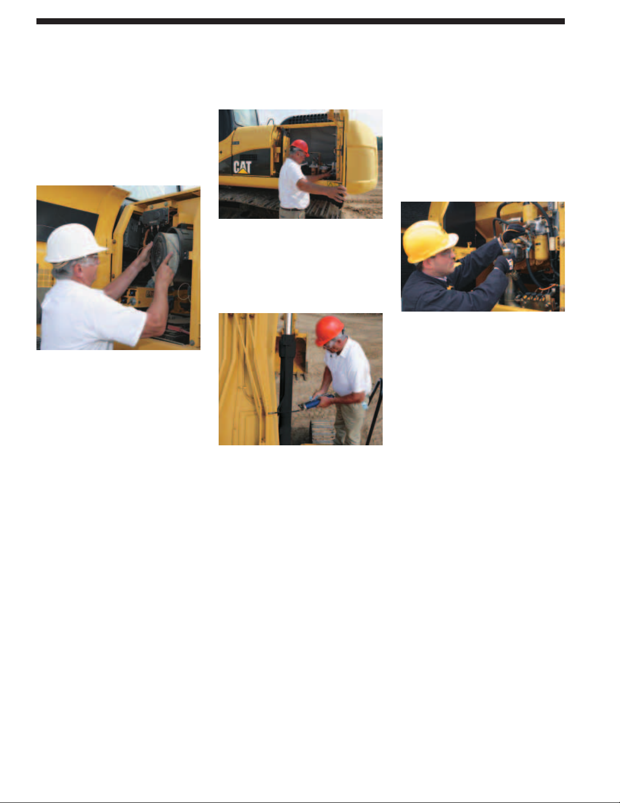
Ground Level Service. The design and
layout of the 324D was made with the
service technician in mind. Many service
locations are easily accessible at ground
level allowing critical maintenance to
get done quickly and efficiently.
Air Filter Compartment. The air filter
features a double-element construction
for superior cleaning efficiency.
When the air cleaner plugs, a warning
is displayed on the monitor screen
inside the cab.
Pump Compartment. A service door
on the right side of the upper structure
allows ground-level access to the pump
and pilot filter.
Radiator Compartment. The left rear
service door allows easy access to the
engine radiator, oil cooler and air-to-airafter-cooler. A reserve tank and drain
cock are attached to the radiator for
simplified maintenance.
Greasing Points. A concentrated remote
greasing block on the boom delivers
grease to hard-to-reach locations on
the front.
Capsule Filter. The hydraulic return
filter, a capsule filter, is situated outside
the hydraulic tank. This filter prevents
contaminants from entering the system
when hydraulic oil is changed and
keeps the operation clean.
Fan Guard. Engine radiator fan is
completely enclosed by fine wire mesh,
reducing the risk of an accident.
Anti-Skid Plate. Anti-skid plate covers
top of storage box and upper structure
to prevent slipping during maintenance.
Diagnostics and Monitoring. The 324D
is equipped with S•O•SSMsampling ports
and hydraulic test ports for the hydraulic
system, engine oil, and for coolant.
A test connection for the Cat Electronic
Technician (Cat ET) service tool is
located in the cab.
Extended Service Interval. 324D service
and maintenance intervals have been
extended to reduce machine service
time and increase machine availability.
12
Service and Maintenance
Simplified service and maintenance features save you time and money.
Page 13
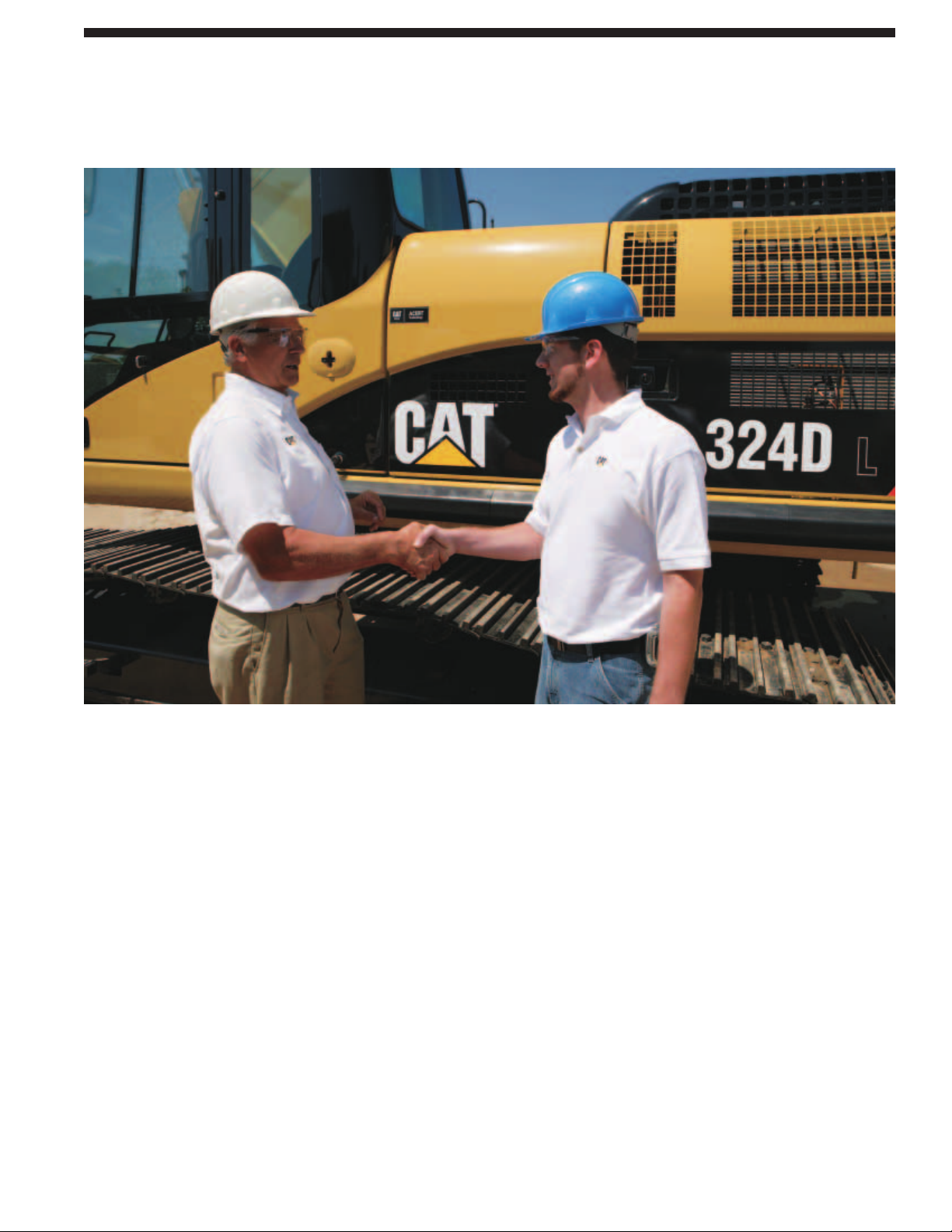
Product Support. You will find nearly
all parts at our dealer parts counter.
Cat dealers utilize a worldwide computer
network to find in-stock parts to minimize
machine down time. Save money with
remanufactured components.
Machine Selection. Make detailed
comparisons of the machines you are
considering before you buy. What are
the job requirements, machine
attachments and operating hours?
What production is needed? Your Cat
dealer can provide recommendations.
Customer Support Agreements.
Cat dealers offer a variety of product
support agreements, and work with
customers to develop a plan the best
meets specific needs. These plans can
cover the entire machine, including
attachments, to help protect the
customer’s investment.
Operation. Improving operating
techniques can boost your profits.
Your Cat dealer has videotapes,
literature and other ideas to help you
increase productivity, and Caterpillar
offers certified operator training classes
to help maximize the return on your
investment.
Maintenance Services. Repair option
programs guarantee the cost of repairs
up front. Diagnostic programs such
as Scheduled Oil Sampling, Coolant
Sampling and Technical Analysis help
you avoid unscheduled repairs.
Replacement. Repair, rebuild, or
replace? Your Cat dealer can help
you evaluate the cost involved so
you can make the right choice.
SAFETY.CAT.COM™.
13
Complete Customer Support
Cat®dealer services help you operate longer with lower costs.
Page 14

14
324D L Hydraulic Excavator specifications
Drive
Maximum Drawbar Pull 227 kN 51,032 lb
Maximum Travel Speed 5.4 km/h 3.4 mph
Hydraulic System
Main Implement System – 220 L/min 58 gal/min
Maximum Flow (2x)
Max. pressure – Equipment 35 000 kPa 5,076 psi
Max. pressure – 36 000 kPa 5,221 psi
Equipment – Heavy
Max. pressure – Travel 35 000 kPa 5,076 psi
Max. pressure – Swing 24 500 kPa 3,553 psi
Pilot System – Maximum flow 32.4 L/min 9 gal/min
Pilot System – 3900 kPa 566 psi
Maximum pressure
Boom Cylinder – Bore 135 mm 5.3 in
Boom Cylinder – Stroke 1305 mm 51.4 in
Stick Cylinder – Bore 140 mm 5.5 in
Stick Cylinder – Stroke 1660 mm 65.4 in
B1 Family Bucket Cylinder – Bore 120 mm 4.7 in
B1 Family Bucket Cylinder – Stroke 1104 mm 43.5 in
CB1 Family Bucket Cylinder – Bore 130 mm 5.1 in
CB1 Family Bucket Cylinder – Stroke 1156 mm 45.5 in
DB Family Bucket Cylinder – Bore 150 mm 5.9 in
DB Family Bucket Cylinder – Stroke 1151 mm 45.3 in
Sound Performance
Performance ANSI/SAE J1166 APR 90
• When properly installed and maintained, the cab offered
by Caterpillar, when tested with doors and windows closed
according to ANSI/SAE J1166 OCT 98, meets OSHA and
MSHA requirements for operator sound exposure limits
in effect at time of manufacture.
• Hearing protection may be needed when operating with an
open operator station and cab (when not properly maintained
or doors/windows open) for extended periods or in noisy
environment.
Standards
Brakes SAE J1026 APR90
Cab/FOGS SAE J1356 FEB88
Engine
Engine Model Cat®C7 with ACERT™ Technology
Net Flywheel Power 140 kW 188 hp
Net Power – ISO 9249 140 kW 188 hp
Net Power – SAE J1349 139 kW 186 hp
Net Power – EEC 80/1269 140 kW 188 hp
Bore 110 mm 4.33 in
Stroke 127 mm 5 in
Displacement 7.2 L 439.4 in
3
• The 324D L meets U.S. EPA Tier III and EU Stage III engine
emissions requirements.
• Net flywheel power advertised is the power available at the
flywheel when the engine is equipped with fan, air cleaner,
muffler and alternator.
• No engine derating needed up to 2300 m (7,500 ft).
Weights
Operating Weight 24 790 kg 54,660 lb
• Base Machine, Reach Boom, R2.95CB1 (9 ft 8 in) Stick, 1.1 m
3
(1.44 yd3) Bucket, 800 mm (32 in) Shoes.
NOTE – The above configuration does not include any
optional attachments.
Track
Standard w/Long Undercarriage 800 mm 32 in
Optional 700 mm 28 in
Optional – Double Grouser 600 mm 23.62 in
Number of Shoes Each Side – 51
Long Undercarriage
Number of Track Rollers 8
Each Side – Long Undercarriage
Number of Carrier Rollers 2
Each Side – Long Undercarriage
Swing Mechanism
Swing Speed 9.6 rpm
Swing Torque 73.4 kN·m 54,137 lb ft
Service Refill Capacities
Fuel Tank Capacity 520 L 137 gal
Cooling System 31 L 8.2 gal
Engine Oil 30 L 8 gal
Swing Drive 10 L 2.6 gal
Final Drive (each) 6 L 1.6 gal
Hydraulic System (including tank) 300 L 79 gal
Hydraulic Tank 145 L 38 gal
Page 15
15
324D L Hydraulic Excavator specifications
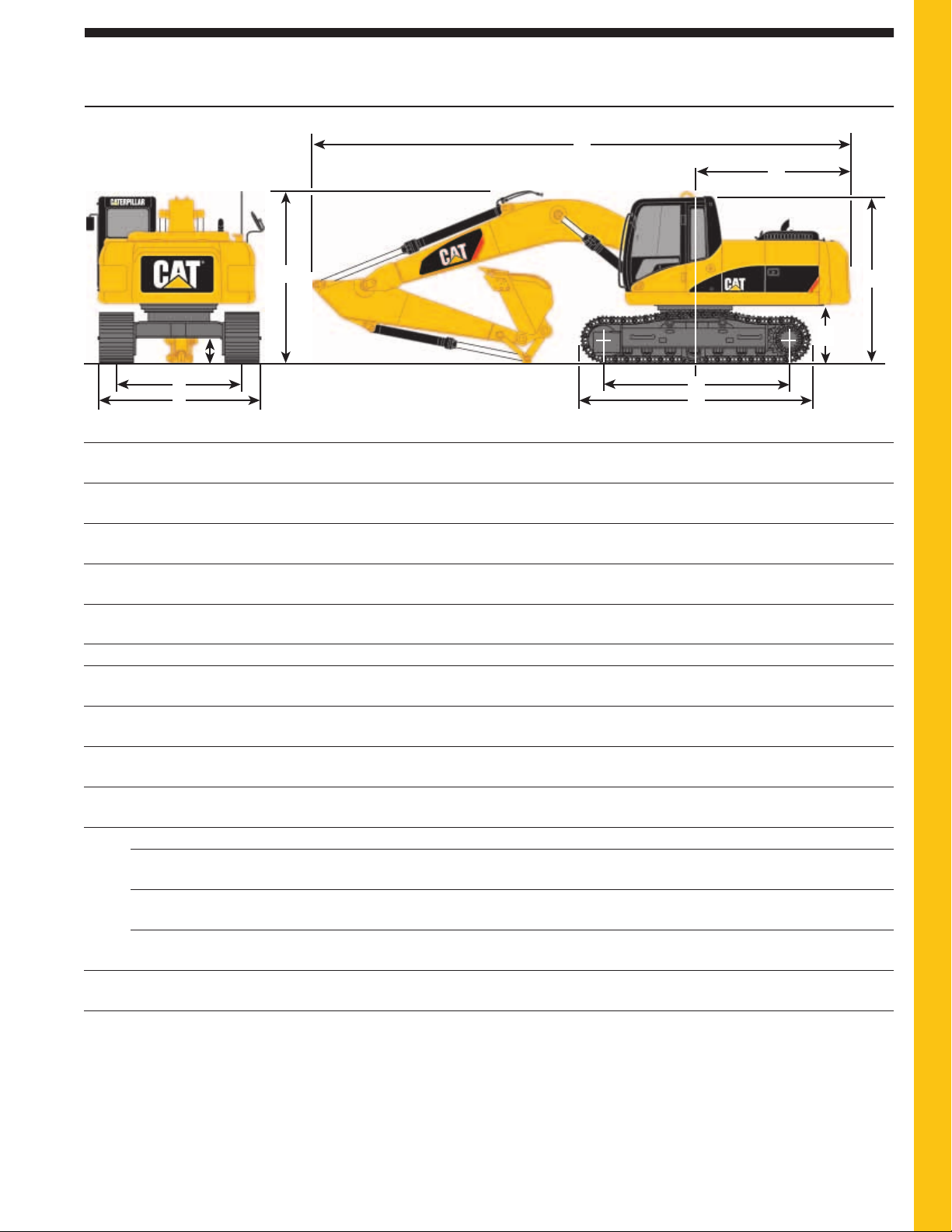
Dimensions
All dimensions are approximate.
2
3
1
10
6
7
8
Boom Options Reach Boom Mass Boom
5.9 m (19'4") 5.3 m (17'5")
Stick Options R3.6B1 R2.95CB1 R2.5CB1 M2.5DB
(11'10") (9'8") (8'2") (8'2")
1 Shipping height 3430 mm 3170 mm 3300 mm 3450 mm
(11'3") (10'5") (10'10") (11'4")
2 Shipping length 10 050 mm 10 060 mm 10 100 mm 9480 mm
(33'0") (33'0") (33'2") (31'1")
3 Tail swing radius 3000 mm 3000 mm 3000 mm 3000 mm
(9'10") (9'10") (9'10") (9'10")
Undercarriage
4 Length to center of rollers 3830 mm 3830 mm 3830 mm 3830 mm
(12'7") (12'7") (12'7") (12'7")
5 Track length 4630 mm 4630 mm 4630 mm 4630 mm
(15'2") (15'2") (15'2") (15'2")
6 Ground clearance 440 mm 440 mm 440 mm 440 mm
(1'5") (1'5") (1'5") (1'5")
7 Track gauge 2590 mm 2590 mm 2590 mm 2590 mm
(8'6") (8'6") (8'6") (8'6")
8 Transport width
800 mm (32") shoes (standard) 3390 mm 3390 mm 3390 mm 3390 mm
(11'1") (11'1") (11'1") (11'1")
700 mm (28") shoes (optional) 3290 mm 3290 mm 3290 mm 3290 mm
(10'10") (10'10") (10'10") (10'10")
600 mm (24") shoes (optional) 3190 mm 3190 mm 3190 mm 3190 mm
(10'6") (10'6") (10'6") (10'6")
9 Cab height 2980 mm 2980 mm 2980 mm 2980 mm
(9'9") (9'9") (9'9") (9'9")
10 Counterweight clearance 1060 mm 1060 mm 1060 mm 1060 mm
(3'6") (3'6") (3'6") (3'6")
4
5
9
Page 16
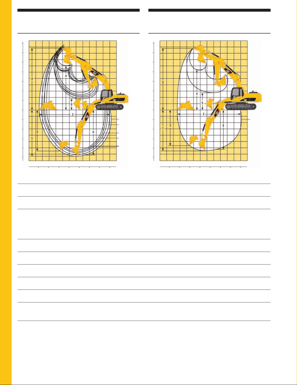
Reach Excavator Working Ranges
16
324D L Hydraulic Excavator specifications
Reach (R) boom configuration
Mass Excavator Working Ranges
Mass (M) boom configuration
MetersFeet
35
10
30
9
8
25
7
20
6
5
15
4
10
3
2
5
1
0
0
1
5
2
3
10
4
15
5
6
20
7
25
8
5101520253035
01234567891011 1
0
3.6 m (11'10")
2.95 m (9'8")
Pin Grabber
2.95 m (9'8")
2.5 m (8'2")
Pin Grabber
2.5 m (8'2")
Meters
Feet
MetersFeet
35
10
30
9
8
25
7
20
6
5
15
4
10
3
2
5
1
0
0
1
5
2
3
10
4
15
5
6
20
7
25
8
01234567891011 1
05101520253035
2.5 m (8'2")
s
Meter
Feet
Boom Options Reach Boom Mass Boom
5.9 m (19'4") 5.3 m (17'5")
Stick Options R3.6B1 R2.95CB1 R2.5CB1 R2.95CB1 R2.5CB1 M2.5DB
(11'10") (9'8") (8'2") (9'8") (8'2") (8'2")
Bucket Options GP-C 1.17 m3HD 1.35 m
3
HD 1.35 m
3
HD 1.35 m
3
HD 1.35 m
3
HD 1.87 m
(1.53 yd3) (1.77 yd3) (1.77 yd3) (1.77 yd3) (1.77 yd3) (2.45 yd3)
with Pin with Pin
Grabber Grabber
Coupler Coupler
1 Maximum 7328 mm 6846 mm 6396 mm 7134 mm 6684 mm 6488 mm
digging depth (24'1") (22'6") (21'0") (23'5") (21'11") (21'3")
2 Maximum reach 10 549 mm 9829 mm 9395 mm 10 094 mm 9700 mm 9446 mm
at ground level (34'7") (32'3") (30'10") (33'1") (31'10") (31'0")
3 Maximum 9887 mm 9946 mm 9750 mm 10 249 mm 10 054 mm 9849 mm
cutting height (32'5") (32'8") (32'0") (33'8") (33'0") (32'4")
4 Maximum 7043 mm 6590 mm 6394 mm 6302 mm 6106 mm 6302 mm
loading height (23'1") (21'7") (21'0") (20'8") (20'0") (20'8")
5 Minimum 1884 mm 2365 mm 2823 mm 2077 mm 2535 mm 2731 mm
loading height (6'2") (7'9") (9'3") (6'10") (8'4") (9'0")
6 Maximum depth 7174 mm 6672 mm 6199 mm 6974 mm 6505 mm 6298 mm
cut for 2440 mm (23'6") (21'11") (20'4") (22'11") (21'4") (20'8")
(8') level bottom
7 Maximum 6575 mm 6075 mm 5633 mm 3877 mm 3490 mm 5694 mm
vertical wall (21'7") (19'11") (18'6") (12'9") (11'5") (18'8")
digging depth
3
Page 17
17
324D L Hydraulic Excavator specifications
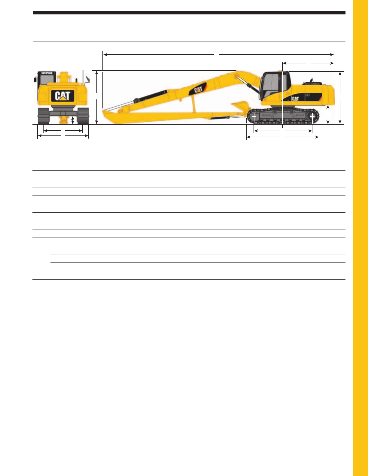
Dimensions
All dimensions are approximate.
2
3
1
6
7
8
Boom Options Super Long Reach Boom
10.2 m (33'6")
Stick Options 7.85 m (25'9")
1 Shipping height 3150 mm (10'4")
2 Shipping length 14 340 mm (47'1")
3 Tail swing radius 3000 mm (9'10")
4 Length to center of rollers 3830 mm (12'7")
5 Track length 4630 mm (15'2")
6 Ground clearance 440 mm (1'5")
7 Track gauge 2590 mm (8'6")
8 Transport width
800 mm (32") shoes (standard) 3390 mm (11'1")
700 mm (28") shoes (optional) 3290 mm (10'10")
600 mm (24") shoes (optional) 3190 mm (10'6")
9 Cab height 2980 mm (9'9")
10 Counterweight clearance 1060 mm (3'6")
9
10
4
5
Page 18
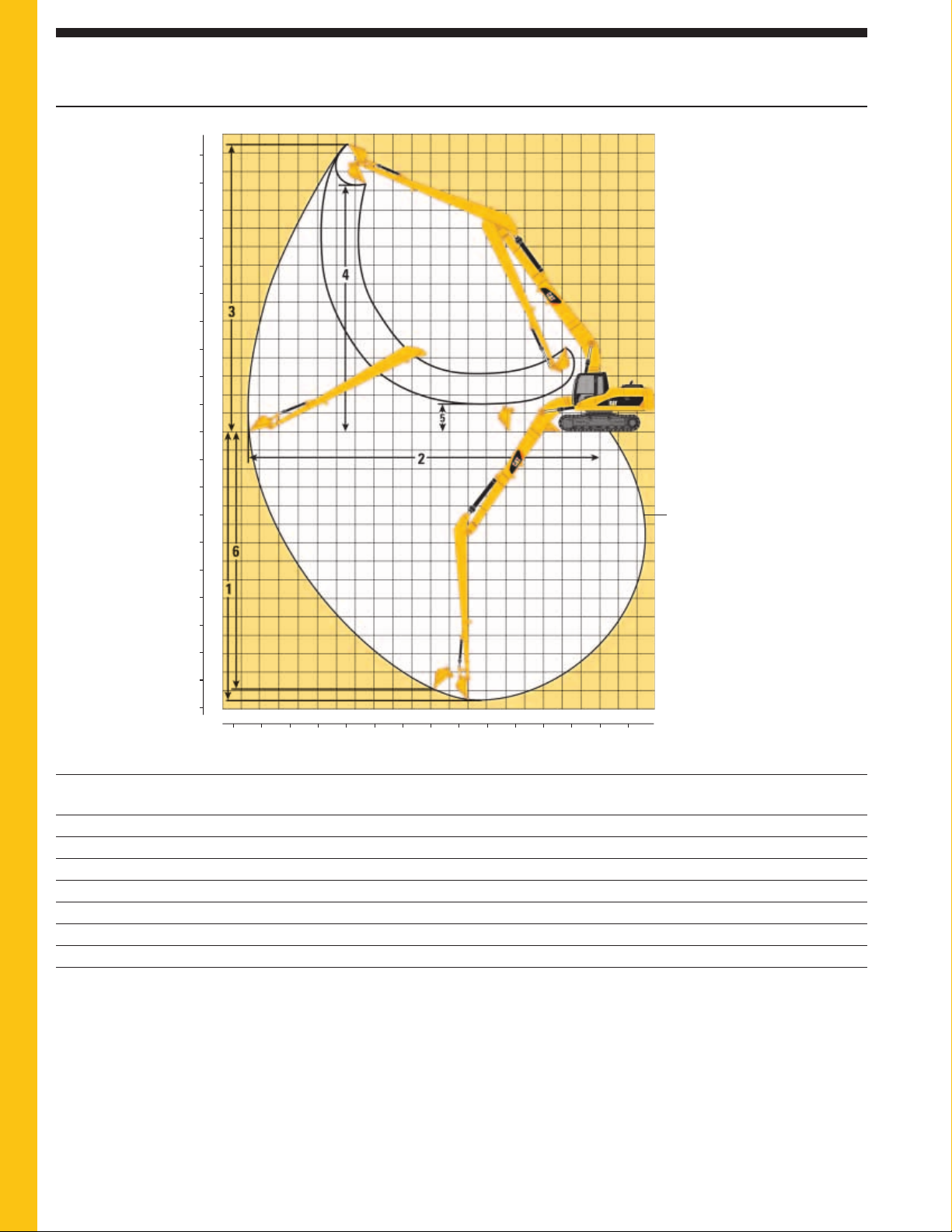
Reach Excavator Working Ranges
18
324D L Hydraulic Excavator specifications
Reach (R) boom configuration
Meters
Feet
15
50
14
45
13
12
40
11
35
10
9
9
30
8
8
25
7
7
6
6
20
5
5
15
4
4
10
3
2
5
1
0
0
1
5
2
10
3
4
15
5
20
6
7
25
8
30
9
10
35
11
40
12
13
45
14
50
15
161819 17
506065 55
121315 10 911
14
87654
35 304045 25 20 15 10 5 -50
3210 -2-1
10.2 m (33'6")
Meters
Feet
Boom Options Super Long Reach Boom
10.2 m (33'6")
Stick Options 7.85 m (25'9")
3
Bucket Options DC 0.61 m
(0.8 yd3)
1 Maximum digging depth 14 594 mm (47'11")
2 Maximum reach at ground level 18 603 mm (61'0")
3 Maximum cutting height 15 411 mm (50'7")
4 Maximum loading height 13 285 mm (43'7")
5 Minimum loading height 1483 mm (4'10")
6 Maximum vertical wall digging depth 13 922 mm (45'7")
Page 19

19
324D L Hydraulic Excavator specifications
Bucket and Stick Forces
Stick Options R3.6B1 R2.95CB1 R2.95CB1 R2.5CB1 R2.5CB1 M2.5DB
with Pin with Pin
Grabber Grabber
Coupler Coupler
kN lb kN lb kN lb kN lb kN lb kN lb
Power Buckets
Bucket Digging Force (ISO) 172 38,667 186 41,814 150 33,721 186 41,814 150 33,721 239 53,729
Stick Digging Force (ISO) 113 25,471 127 28,551 119 26,752 148 33,272 137 30,799 147 33,047
Bucket Digging Force (SAE) 152 34,171 163 36,644 145 32,597 163 36,644 146 32,822 210 47,210
Stick Digging Force (SAE) 111 24,954 123 27,651 118 26,527 143 32,148 136 30,574 142 31,923
HD and HDR Buckets
Bucket Digging Force (ISO) 147 33,047 166 37,318 143 32,148 167 37,543 144 32,372 215 48,334
Stick Digging Force (ISO) 111 24,954 124 27,876 117 26,303 144 32,372 135 30,349 143 32,148
Bucket Digging Force (SAE) 132 29,675 147 33,047 131 29,450 147 33,047 132 29,675 190 42,714
Stick Digging Force (SAE) 108 24,279 120 26,977 114 25,628 139 31,248 131 29,450 138 31,024
Major Component Weights
kg lb
Base machine with counterweight (without front linkage)
With 800 mm (32") shoes 20 740 45,724
Two boom cylinders (each) 227 500
Counterweight
Standard counterweight 4520 9,965
Super long reach counterweight 6760 14,903
Boom (includes lines, pins and stick cylinder)
Reach boom 5.9 m (19'5") 2033 4,482
Mass boom 5.3 m (17'5") 2138 4,713
Super long reach boom 10.2 m (33'5") 3580 7,893
Stick (includes lines, pins, bucket cylinder and linkage)
R3.6B1 (11'10") 1199 2,643
R2.95CB1 (9'8") 1208 2,663
R2.5CB1 (8'2") 1149 2,533
M2.5DB (8'2") 1470 3,241
Super long reach stick 7.85 m (25'9") 1610 3,549
Page 20
Bucket Specifications and Compatibility
20
324D L Hydraulic Excavator specifications
Bucket Type Adaptor Capacity* Width Tip Teeth Total Reach Boom
3
m
yd3mm in mm in Qty kg lb R3.6B1 R2.95CB1 R2.5CB1
Radius Weight Stick
CB1 Family Buckets
General Purpose – K90 0.63 0.82 610 24 1656.3 65.2 3 729 1,606 — ss
Capacity
K90 0.86 1.12 762 30 1656.3 65.2 4 847 1,868 — ss
K90 1.09 1.43 914 36 1656.3 65.2 5 951 2,097 — ss
K90 1.34 1.75 1067 42 1656.3 65.2 5 1024 2,258 — ss
K90 1.58 2.07 1219 48 1656.3 65.2 6 1121 2,471 — ns
K90 1.83 2.39 1372 54 1656.3 65.2 7 1218 2,684 — *n
Heavy Duty K100 0.53 0.69 610 24 1686.3 66.4 3 780 1,720 — ss
K100 0.73 0.95 762 30 1686.3 66.4 3 858 1,891 — ss
K100 0.93 1.22 914 36 1686.3 66.4 4 982 2,165 — ss
K100 1.14 1.49 1067 42 1686.3 66.4 5 1073 2,365 — ss
K100 1.35 1.77 1219 48 1686.3 66.4 5 1143 2,519 — ss
K100 1.57 2.05 1372 54 1686.3 66.4 6 1238 2,730 — nn
K100 1.78 2.33 1524 60 1686.3 66.4 7 1334 2,941 — **
K100 1.99 2.60 1676 66 1686.3 66.4 7 1406 3,101 — ∴ *
Heavy Duty Rock K100 0.73 0.95 762 30 1686.3 66.4 3 965 2,127 — ss
K100 0.93 1.22 914 36 1686.3 66.4 4 1073 2,365 — ss
K100 1.14 1.49 1067 42 1686.3 66.4 5 1174 2,588 — ss
K100 1.35 1.77 1219 48 1686.3 66.4 5 1259 2,775 — ss
Heavy Duty Power K100 1.12 1.46 1067 42 1592.1 62.7 5 1060 2,337 — ss
K100 1.33 1.74 1219 48 1592.1 62.7 5 1137 2,507 — ss
K100 1.53 2.00 1372 54 1592.1 62.7 6 1237 2,727 — ns
Ditch Cleaning N/A 1.25 1.63 1534 60 1262.0 49.7 — 739 1,629 — ss
N/A 1.53 2.00 1830 72 1262.0 49.7 — 837 1,845 — ss
Assumptions for maximum material density rating:
1. Front linkage fully extended at ground line
2. Bucket curled
3. 100% bucket fill factor
Based on SAE J296, some calculations of capacity specs fall on borderlines. Rounding
*
may allow two buckets to have the same English rating, but different metric ratings.
s 2100 kg/m3(3,500 lb/yd3) max material density
n 1800 kg/m3(3,000 lb/yd3) max material density
* 1500 kg/m3(2,500 lb/yd3) max material density
∴ 1200 kg/m3(2,000 lb/yd3) max material density
— Not Available
Page 21
21
324D L Hydraulic Excavator specifications
Bucket Specifications and Compatibility
Bucket Type Adaptor Capacity* Width Tip Teeth Total Reach Boom
3
m
yd
3
mm in mm in Qty kg lb R3.6B1
B Family Buckets
General Purpose – K80 0.57 0.74 610 24 1524.0 60.0 3 646 1,425 s
Capacity K80 0.77 1.01 762 30 1524.0 60.0 4 704 1,551 s
K80 0.95 1.24 914 36 1524.0 60.0 5 798 1,760 s
K80 1.17 1.53 1067 42 1524.0 60.0 5 857 1,889 s
K80 1.39 1.82 1219 48 1524.0 60.0 6 1002 2,208 n
K80 1.57 2.05 1372 54 1524.0 60.0 6 1011 2,228 n
Heavy Duty K90 0.54 0.70 610 24 1578.0 62.1 3 680 1,500 s
K90 0.77 1.00 762 30 1578.0 62.1 4 772 1,702 s
K90 0.84 1.10 914 36 1578.0 62.1 5 852 1,878 s
K90 1.07 1.40 1067 42 1578.0 62.1 5 913 2,013 s
K90 1.22 1.60 1219 48 1578.0 62.1 6 1007 2,220 s
K90 1.38 1.80 1372 54 1578.0 62.1 6 1084 2,389 n
Heavy Duty Rock K90 0.54 0.70 610 24 1578.0 62.1 3 731 1,612 s
K90 0.77 1.00 762 30 1578.0 62.1 4 828 1,826 s
K90 0.84 1.10 914 36 1578.0 62.1 5 922 2,033 s
K90 1.07 1.40 1067 42 1578.0 62.1 5 992 2,187 s
Heavy Duty Power K90 0.84 1.10 914 36 1404.0 55.3 5 843 1,858 s
K90 0.99 1.30 1067 42 1404.0 55.3 5 902 1,989 s
K90 1.15 1.50 1219 48 1404.0 55.3 6 1003 2,211 s
Ditch Cleaning N/A 0.99 1.30 1524 60 1143.0 45.0 — 736 1,623 s
N/A 1.24 1.62 1830 72 1143.0 45.0 — 844 1,861 s
Radius Weight Stick
Assumptions for maximum material density rating:
1. Front linkage fully extended at ground line
2. Bucket curled
3. 100% bucket fill factor
Based on SAE J296, some calculations of capacity specs fall on borderlines. Rounding
*
may allow two buckets to have the same English rating, but different metric ratings.
s 2100 kg/m3(3,500 lb/yd3) max material density
n 1800 kg/m3(3,000 lb/yd3) max material density
Page 22
Bucket Specifications and Compatibility
22
324D L Hydraulic Excavator specifications
Bucket Type Adaptor Capacity* Width Tip Teeth Total Mass Boom
3
m
yd
3
mm in mm in Qty kg lb M2.5DB
DB Family Buckets
General Purpose K100 0.94 1.23 762 30 1753.4 69.0 3 993 2,189 s
K100 1.19 1.56 914 36 1753.4 69.0 4 1088 2,398 s
K100 1.46 1.91 1067 42 1753.4 69.0 5 1200 2,646 s
K100 1.73 2.26 1219 48 1753.4 69.0 5 1288 2,839 n
K100 2.00 2.62 1372 54 1753.4 69.0 6 1401 3,089 *
K100 2.27 2.97 1524 60 1753.4 69.0 7 1515 3,339 ∴
K100 2.55 3.34 1676 66 1753.4 69.0 7 1602 3,532 ∴
Heavy Duty K110 0.74 0.97 762 30 1779.1 70.0 3 1070 2,358 s
K110 0.95 1.24 914 36 1779.1 70.0 4 1216 2,682 s
K110 1.18 1.54 1067 42 1779.1 70.0 4 1310 2,889 s
K110 1.41 1.84 1219 48 1779.1 70.0 5 1441 3,178 s
K110 1.64 2.15 1372 54 1779.1 70.0 5 1539 3,393 n
K110 1.87 2.45 1524 60 1779.1 70.0 6 1672 3,686 *
K110 2.10 2.75 1676 66 1779.1 70.0 7 1805 3,979 ∴
K110 2.34 3.06 1829 72 1779.1 70.0 7 1904 4,197 ∴
Heavy Duty Rock K110 0.74 0.97 762 30 1779.1 70.0 3 1131 2,493 s
K110 0.95 1.24 914 36 1779.1 70.0 4 1293 2,849 s
K110 1.18 1.54 1067 42 1779.1 70.0 4 1400 3,086 s
K110 1.41 1.84 1219 48 1779.1 70.0 5 1547 3,411 s
K110 1.64 2.15 1372 54 1779.1 70.0 5 1660 3,659 *
Heavy Duty Power K110 0.95 1.24 914 36 1681.8 66.2 4 1192 2,628 s
K110 1.40 1.83 1219 48 1681.8 66.2 5 1421 3,132 s
K110 1.63 2.13 1372 54 1681.8 66.2 5 1518 3,346 n
K110 1.86 2.43 1524 60 1681.8 66.2 6 1650 3,637 *
Ditch Cleaning N/A 1.63 2.13 1524 60 1410.0 55.5 — 1088 2,399 n
N/A 1.91 2.50 1830 72 1410.0 55.5 — 1217 2,683 *
Radius Weight Stick
Assumptions for maximum material density rating:
1. Front linkage fully extended at ground line
2. Bucket curled
3. 100% bucket fill factor
Based on SAE J296, some calculations of capacity specs fall on borderlines. Rounding
*
may allow two buckets to have the same English rating, but different metric ratings.
s 2100 kg/m3(3,500 lb/yd3) max material density
n 1800 kg/m3(3,000 lb/yd3) max material density
* 1500 kg/m3(2,500 lb/yd3) max material density
∴ 1200 kg/m3(2,000 lb/yd3) max material density
Page 23

23
324D L Hydraulic Excavator specifications
324D L Work Tool Matching Guide
Boom Options Reach Boom Mass Boom
5.9 m (19'4") 5.3 m (17'5")
Stick Options R3.6B1 R2.95CB1 R2.5CB1 M2.5DB
(11'10") (9'8") (8'2") (8'2")
Hydraulic Hammer H120Cs/ H120Cs/ H120Cs/ H120Cs/
H130s/ H130s/ H130s/ H130s/
H140Ds H140Ds H140Ds H140Ds
Multi-Processor MP15/MP20 MP15/MP20 MP15/MP20 N/A
MP30 N/A
360° Scrap Shear S320 S320 S320 S320
S340 N/A
Mechanical Shear S115 S115 S115 S115
Mechanical Pulverizer P115 P120 P120 P120
Trash Grapple** Available as field installed attachment only
Contractors’ Grapple** Available as field installed attachment only
Rotating Sorting/Demolition Grapple G315 G315 G315 G315
Vibratory Plate Compactor CVP110 CVP110 CVP110 CVP110
Hydraulic Thumb** Available as field installed attachment only
Dedicated Quick Coupler** Available as field installed attachment only
Pin-Grabber Quick Coupler Available as factory or field installed attachment N/A
** S325 only without PG Coupler.
** Contact Cat Work Tools for availability and proper matching.
Page 24
➤
➤
➤
➤
➤
➤
➤
➤
➤
➤
➤
➤
➤
➤
➤
➤
➤
➤
➤
➤
➤
➤
➤
➤
➤
➤
➤
➤
➤
➤
➤
➤
➤
➤
➤
➤
➤
➤
➤
➤
➤
➤
➤
➤
➤
➤
➤
➤
➤
➤
➤
➤
➤
➤
➤
➤
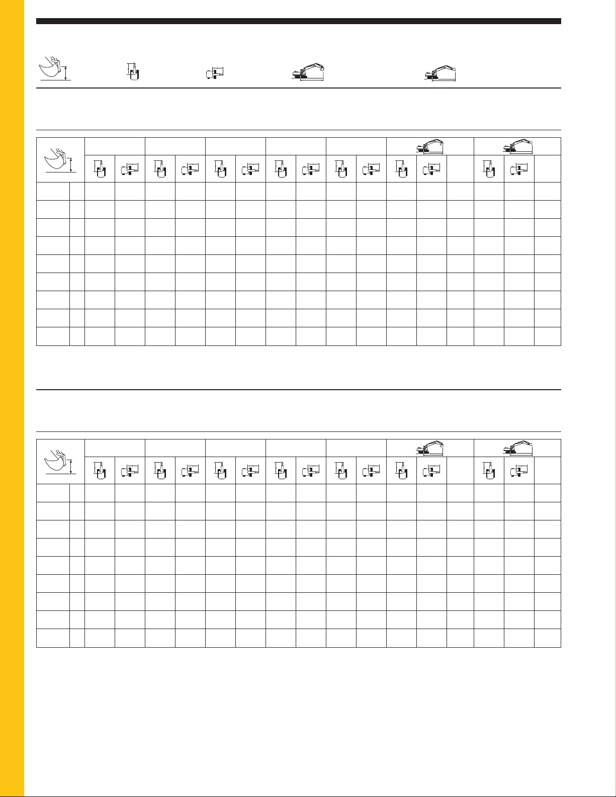
Reach Boom Lift Capacities
➤
➤
➤
➤
24
324D L Hydraulic Excavator specifications
Load Point
Height
Load Radius
Over Front
BOOM – 5.9 m (19'4")
R3.6B1 STICK – 3.6 m (11'10")
Load Radius
Over Side
Load at Maximum
Reach – Bucket Curled
BUCKET – 1067 mm (42") HDP
with General Duty Tips
902 kg (1,989 lb)
SHOES – 800 mm (32") triple grouser
UNDERCARRIAGE – Long
HEAVY LIFT – On
Load at Maximum
Reach – Bucket Extended
3.0 m (10.0 ft) 4.5 m (15.0 ft) 6.0 m (20.0 ft) 7.5 m (25.0 ft) 9.0 m (30.0 ft)
m
ft ft
7.5 m kg *3630 *3630 *3260 *3260 7.65 *2810 *2810 7.49
25 ft lb *8,000 *8,000 *7,250 *7,250 24.8 *6,190 *6,190 24.6
6.0 m kg *4770 4410 *3130 *3130 8.59 *2580 *2580 8.82
20 ft lb *10,200 9,450 *6,900 *6,900 28.0 *5,700 *5,700 28.6
4.5 m kg *5390 4320 *3720 3010 *3140 2880 9.18 *2510 *2510 9.66
15 ft lb *11,800 9,250 *7,050 6,400 *6,900 6,400 30.1 *5,550 *5,550 31.6
3.0 m kg *13 090 *13 090 *8750 *8750 *6970 6070 *6040 4150 4710 2950 *3270 2630 9.5 *2540 2440 10.16
10 ft lb *28,850 *28,850 *18,850 *18,850 *15,100 13,050 *13,150 8,900 *9,750 6,300 *7,200 5,800 31.2 *5,600 5,400 33.3
1.5 m kg *7120 *7120 *11 340 8950 *8310 5690 6290 3950 4620 2860 *3530 2530 9.58 *2650 2270 10.38
5 ft lb *17,050 *17,050 *24,450 19,250 *18,000 12,250 13,500 8,500 9,900 6,100 *7,750 5,600 31.4 *5,850 5,000 34.1
Ground kg *6530 *6530 *13 130 8370 8760 5380 6100 3780 4530 2770 *3960 2560 9.41 *2860 2230 10.35
Line lb *14,950 *14,950 *28,400 18,000 18,800 11,550 13,100 8,100 9,700 5,950 *8,700 5,650 30.9 *6,300 4,900 34.0
–1.5 m kg *9060 *9060 *13 830 8100 8550 5190 5980 3670 4490 2740 8.99 *3200 2300 10.05
–5 ft lb *20,600 *20,600 *29,950 17,400 18,350 11,150 12,850 7,900 9,900 6,050 29.5 *7,050 5,100 33.0
–3.0 m kg *13 070 *13 070 *13 560 8060 8480 5130 5950 3650 5130 3140 8.27 *3730 2540 9.47
–10 ft lb *29,700 *29,700 *29,350 17,300 18,200 11,050 12,800 7,850 11,350 6,950 27.0 *8,250 5,600 31.0
–4.5 m kg *16 150 *16 150 *12 220 8190 8570 5220 6490 4000 7.17 *4670 3050 8.54
–15 ft lb *36,250 36,000 *26,300 17,600 18,450 11,250 14,550 8,950 23.3 *10,400 6,750 27.9
* Limited by hydraulic capacity rather than tipping load. The above loads are in compliance with SAE hydraulic excavator lift capacity rating standard J1097.
They do not exceed 87% of hydraulic lifting capacity or 75% of tipping capacity. Weight of all lifting accessories must be deducted from the above
lifting capacities.
m
BOOM – 5.9 m (19'4")
R2.95CB1 STICK – 2.95 m (9'8")
BUCKET – 914 mm (36") HD
with General Duty Tips
982 kg (2,165 lb)
SHOES – 800 mm (32") triple grouser
UNDERCARRIAGE – Long
HEAVY LIFT – On
1.5 m (5.0 ft) 3.0 m (10.0 ft) 4.5 m (15.0 ft) 6.0 m (20.0 ft) 7.5 m (25.0 ft)
m
ft ft
7.5 m kg *4130 *4130 6.94 *2990 *2990 8.26
25 ft lb *9,150 *9,150 22.4 *6,600 *6,600 26.8
6.0 m kg *5270 4220 *3920 3710 7.96 *2900 *2900 9.19
20 ft lb *10,800 9,000 *8,650 8,300 26.0 *6,400 *6,400 30.0
4.5 m kg *6490 6220 *5920 4170 *3930 3160 8.6 *2940 2620 9.74
15 ft lb *14,100 13,350 *12,950 8,950 *8,650 7,000 28.1 *6,450 5,800 31.9
3.0 m kg *10 050 9470 *7690 5920 6380 4040 *4090 2870 8.94 *3070 2430 9.98
10 ft lb *21,650 20,400 *16,650 12,750 13,700 8,650 *9,000 6,350 29.3 *6,750 5,350 32.7
1.5 m kg *12 400 8760 *8910 5600 6210 3880 *4430 2770 9.02 *3310 2390 9.94
5 ft lb *26,750 18,850 *19,300 12,050 13,350 8,350 *9,750 6,100 29.6 *7,300 5,250 32.6
Ground kg *4830 *4830 *13 710 8330 8730 5350 6070 3750 4620 2830 8.84 *3700 2490 9.62
Line lb *11,200 *11,200 *29,650 17,900 18,750 11,500 13,050 8,050 10,200 6,250 29.0 *8,150 5,500 31.6
–1.5 m kg *5140 *5140 *8880 *8880 *13 930 8180 8580 5220 5990 3680 5010 3070 8.39 *4340 2790 9.0
–5 ft lb *11,550 *11,550 *20,250 *20,250 *30,200 17,600 18,450 11,250 12,900 7,900 11,050 6,800 27.5 *9,600 6,150 29.5
–3.0 m kg *9620 *9620 *14 460 *14 460 *13 180 8220 8580 5220 6020 3710 5880 3630 7.62 *3770 3450 7.97
–10 ft lb *21,650 *21,650 *32,950 *32,950 *28,500 17,650 18,450 11,250 13,270 8,170 13,050 8,050 24.9 *8,200 7,700 26.0
–4.5 m kg *15 780 *15 780 *11 200 8430 *8000 5380 *7120 4880 6.41
–15 ft lb *33,900 *33,900 *24,000 18,150 *16,850 11,600 *15,700 11,000 20.8
* Limited by hydraulic capacity rather than tipping load. The above loads are in compliance with SAE hydraulic excavator lift capacity rating standard J1097.
They do not exceed 87% of hydraulic lifting capacity or 75% of tipping capacity. Weight of all lifting accessories must be deducted from the above
lifting capacities.
Always refer to the appropriate Operation and Maintenance Manual for specific product information.
m
Page 25
25
324D L Hydraulic Excavator specifications
➤
➤
➤
➤
➤
➤
➤
➤
➤
➤
➤
➤
➤
➤
➤
➤
➤
➤
➤
➤
➤
➤
➤
➤
➤
➤
➤
➤
➤
➤
➤
➤
➤
➤
➤
➤
➤
➤
➤
➤
➤
➤
➤
➤
➤
➤
➤
➤
➤
➤
➤
➤
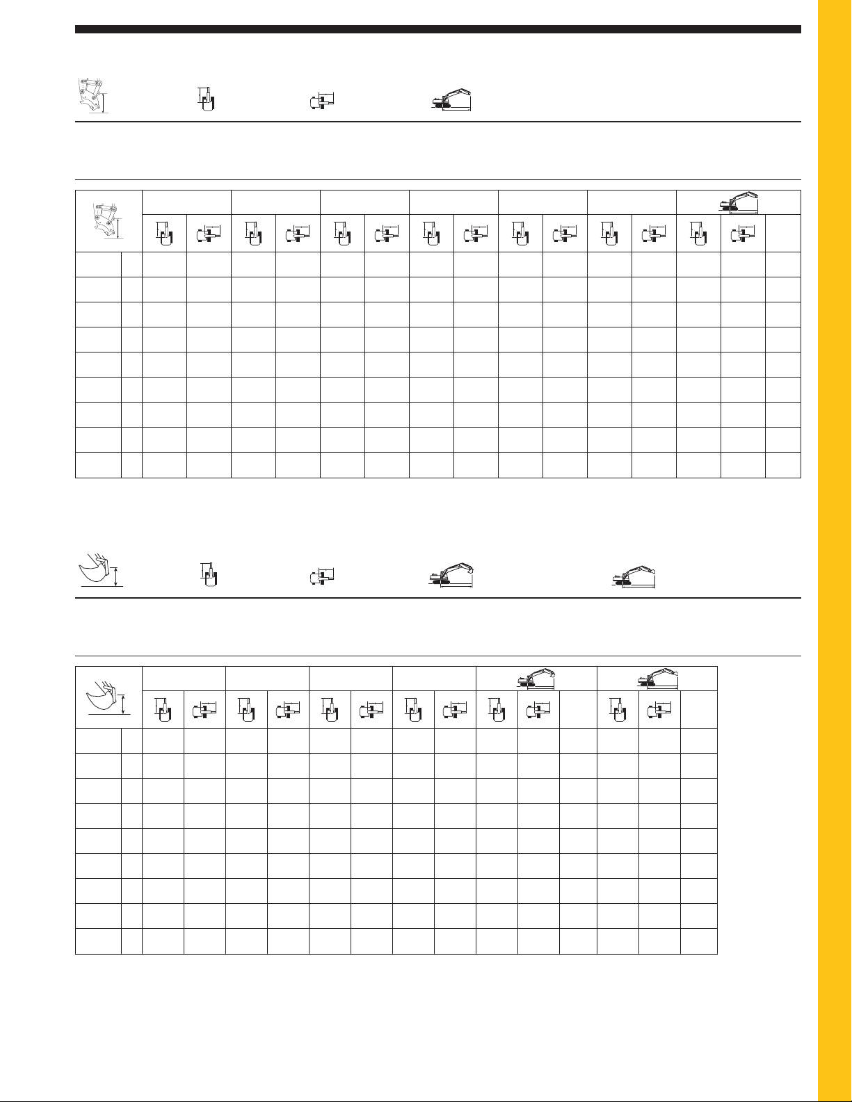
Reach Boom Lift Capacities
➤
➤
➤
➤
➤
➤
➤
➤
Load Point
Height
Load Radius
Over Front
BOOM – 5.9 m (19'4")
R2.95CB1 STICK – 2.95 m (9'8")
Load Radius
Over Side
BUCKET – No Bucket
Bare Quick Coupler
Load at Maximum
Reach – Coupler Curled
SHOES – 800 mm (32") triple grouser
UNDERCARRIAGE – Long
HEAVY LIFT – On
1.5 m (5.0 ft) 3.0 m (10.0 ft) 4.5 m (15.0 ft) 6.0 m (20.0 ft) 7.5 m (25.0 ft) 9.0 m (30.0 ft)
7.5 m kg *4590 *4590 6.97
25 ft lb *10,200 *10,200 22.5
6.0 m kg *5690 4570 *4340 4060 7.99
20 ft lb *11,800 9,800 *9,600 9,050 26.0
4.5 m kg *6800 6490 *6280 4480 *4290 3500 8.62
15 ft lb *14,800 13,950 *13,750 9,650 *9,450 7,750 28.2
3.0 m kg *10 270 9630 *7980 6150 6660 4330 *4410 3200 8.96
10 ft lb *22,100 20,750 *17,300 13,250 14,300 9,300 *9,700 7,050 29.4
1.5 m kg *12 630 8920 *9190 5820 6470 4150 4850 3110 *4700 3080 9.04
5 ft lb *27,250 19,200 19,800 12,550 13,950 8,950 10,690 6,850 *10,350 6,800 29.7
Ground kg *5290 *5290 *13 960 8500 8930 5570 6320 4020 4910 3130 8.86
Line lb *12,200 *12,200 *30,200 18,300 19,200 12,000 13,600 8,650 10,800 6,900 29.1
–1.5 m kg *5450 *5450 *9350 *9350 *14 200 8360 8780 5440 6240 3950 5280 3350 8.41
–5 ft lb *12,200 *12,200 *21,300 *21,300 30,500 17,950 18,900 11,700 13,450 8,500 11,650 7,400 27.6
–3.0 m kg *10 000 *10 000 *14 960 *14 960 *13 450 8390 8780 5440 6280 3980 6110 3880 7.64
–10 ft lb *22,500 *22,500 *34,100 *34,100 *29,100 18,050 18,900 11,750 13,840 8,770 13,550 8,600 25.0
–4.5 m kg *16 030 *16 030 *11 480 8590 *8310 5590 *7390 5090 6.44
–15 ft lb *34,450 *34,450 *24,600 18,500 *17,600 12,100 *16,300 11,400 20.9
* Limited by hydraulic capacity rather than tipping load. The above loads are in compliance with SAE hydraulic excavator lift capacity rating standard J1097.
They do not exceed 87% of hydraulic lifting capacity or 75% of tipping capacity. Weight of all lifting accessories must be deducted from the above
lifting capacities.
m
ft
Load Point
Height
Load Radius
Over Front
BOOM – 5.9 m (19'4")
R2.5CB1 STICK – 2.5 m (8'2")
Load Radius
Over Side
BUCKET – 914 mm (36") HD
with General Duty Tips
982 kg (2,165 lb)
Load at Maximum
Reach – Bucket Curled
SHOES – 800 mm (32") triple grouser
UNDERCARRIAGE – Long
HEAVY LIFT – On
Load at Maximum
Reach – Bucket Extended
3.0 m (10.0 ft) 4.5 m (15.0 ft) 6.0 m (20.0 ft) 7.5 m (25.0 ft
mm
ft ft
7.5 m kg *6110 *6110 *5830 5540 6.4 *4060 *4060 7.73
25 ft lb *13,650 13,400 *12,950 12,600 20.6 *9,000 *9,000 25.0
6.0 m kg *6220 *6220 *5500 4130 7.49 *3950 3320 8.74
20 ft lb *13,600 13,550 *12,150 9,250 24.4 *8,700 7,400 28.5
4.5 m kg *8410 *8410 *7020 6150 *6330 4120 *5500 3470 8.17 *3990 2860 9.32
15 ft lb *18,100 *18,100 *15,250 13,200 *13,850 8,850 *12,100 7,700 26.7 *8,800 6,350 30.5
3.0 m kg *10 880 9280 *8170 5860 6350 4010 5040 3140 8.53 *4170 2640 9.57
10 ft lb *23,400 20,000 *17,650 12,600 13,600 8,600 11,150 6,950 28.0 *9,150 5,850 31.4
1.5 m kg *12 980 8620 8950 5550 6200 3880 4900 3030 8.61 4210 2600 9.53
5 ft lb *28,000 18,550 19,250 11,950 13,300 8,300 10,800 6,700 28.3 9,250 5,700 31.3
Ground kg *13 930 8270 8710 5340 6080 3770 5030 3100 8.42 4420 2720 9.2
Line lb *30,150 17,800 18,700 11,500 13,050 8,100 11,100 6,850 27.6 9,750 6,000 30.2
–1.5 m kg *9100 *9100 *13 820 8200 8610 5250 6030 3730 5510 3400 7.95 *4690 3090 8.53
–5 ft lb *20,800 *20,800 *29,950 17,650 18,500 11,300 13,000 8,000 12,150 7,500 26.1 *10,300 6,850 27.9
–3.0 m kg *16 530 *16 530 *12 750 8300 8660 5290 6600 4090 7.13 *3340 *3340 7.43
–10 ft lb *37,800 36,450 *27,550 17,850 18,600 11,400 14,650 9,100 23.3 *7,250 *7,250 24.2
–4.5 m kg *14 110 *14 110 *10 260 8580 *7340 5790 5.81
–15 ft lb *30,250 *30,250 *21,850 18,500 *16,180 *12,760 19.1
* Limited by hydraulic capacity rather than tipping load. The above loads are in compliance with SAE hydraulic excavator lift capacity rating standard J1097.
They do not exceed 87% of hydraulic lifting capacity or 75% of tipping capacity. Weight of all lifting accessories must be deducted from the above
lifting capacities.
Always refer to the appropriate Operation and Maintenance Manual for specific product information.
Page 26
➤
➤
➤
➤
➤
➤
➤
➤
➤
➤
➤
➤
➤
➤
➤
➤
➤
➤
➤
➤
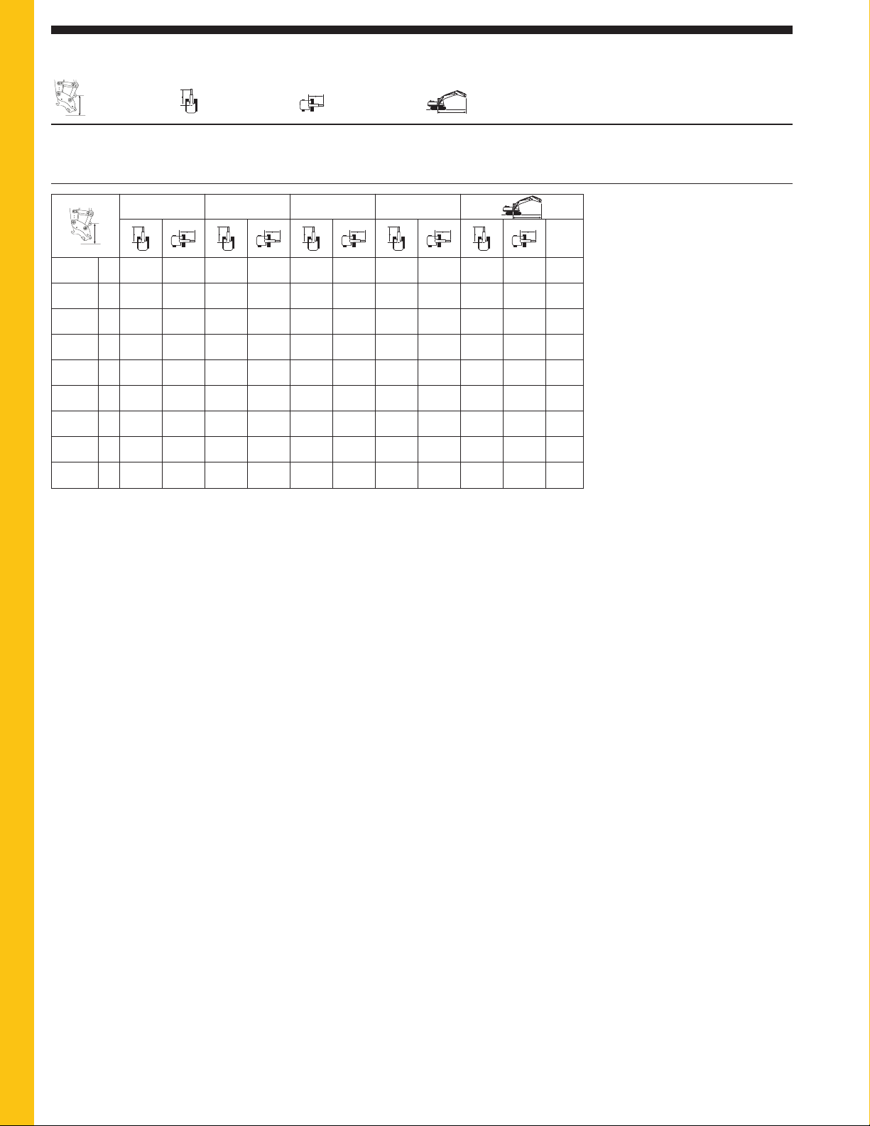
Reach Boom Lift Capacities
➤
➤
➤
➤
26
324D L Hydraulic Excavator specifications
Load Point
Height
Load Radius
Over Front
BOOM – 5.9 m (19'4")
R2.5CB1 STICK – 2.5 m (8'2")
Load Radius
Over Side
BUCKET – No Bucket
Bare Quick Coupler
Load at Maximum
Reach – Coupler Curled
SHOES – 800 mm (32") triple grouser
UNDERCARRIAGE – Long
HEAVY LIFT – On
3.0 m (10.0 ft) 4.5 m (15.0 ft) 6.0 m (20.0 ft) 7.5 m (25.0 ft)
m
ft
7.5 m kg *6530 *6530 *6300 5890 6.43
25 ft lb *14,600 14,300 *14,000 13,400 20.7
6.0 m kg *6580 *6580 *6010 4500 *5910 4480 7.52
20 ft lb *14,400 14,250 *13,240 9,920 *13,050 10,000 24.5
4.5 m kg *8640 *8640 *7330 6410 *6700 4450 5830 3800 8.19
15 ft lb *18,650 *18,650 *15,950 13,800 14,600 9,550 *12,900 8,450 26.8
3.0 m kg *11 090 9440 *8450 6090 6630 4300 5350 3460 8.55
10 ft lb *23,850 20,350 *18,300 13,100 14,250 9,250 11,800 7,650 28.0
1.5 m kg *13 230 8790 9150 5780 6460 4150 5190 3330 8.63
5 ft lb *28,550 18,950 19,700 12,450 13,900 8,950 11,450 7,350 28.3
Ground kg *14 200 8460 8910 5560 6340 4030 5310 3390 8.45
Line lb *30,750 18,200 19,150 12,000 13,650 8,700 11,700 7,470 27.7
–1.5 m kg *9520 *9520 *14 100 8390 8810 5470 6290 3990 5760 3670 7.97
–5 ft lb *21,750 *21,750 30,550 18,050 18,950 11,800 13,550 8,600 12,750 8,100 26.1
–3.0 m kg *16 990 *16 990 *13 030 8470 8850 5510 6820 4330 7.15
–10 ft lb *38,850 36,700 *28,200 18,200 19,050 11,900 15,150 9,600 23.4
–4.5 m kg *14 370 *14 370 *10 540 8730 *7590 5960 5.84
–15 ft lb *30,850 *30,850 *22,500 18,800 *16,700 13,450 18.9
* Limited by hydraulic capacity rather than tipping load. The above loads are in compliance with SAE hydraulic excavator lift capacity rating standard J1097.
They do not exceed 87% of hydraulic lifting capacity or 75% of tipping capacity. Weight of all lifting accessories must be deducted from the above
lifting capacities.
Always refer to the appropriate Operation and Maintenance Manual for specific product information.
Page 27
27
324D L Hydraulic Excavator specifications
➤
➤
➤
➤
➤
➤
➤
➤
➤
➤
➤
➤
➤
➤
➤
➤
➤
➤
➤
➤
➤
➤
➤
➤
➤
➤
➤
➤
➤
➤
➤
➤
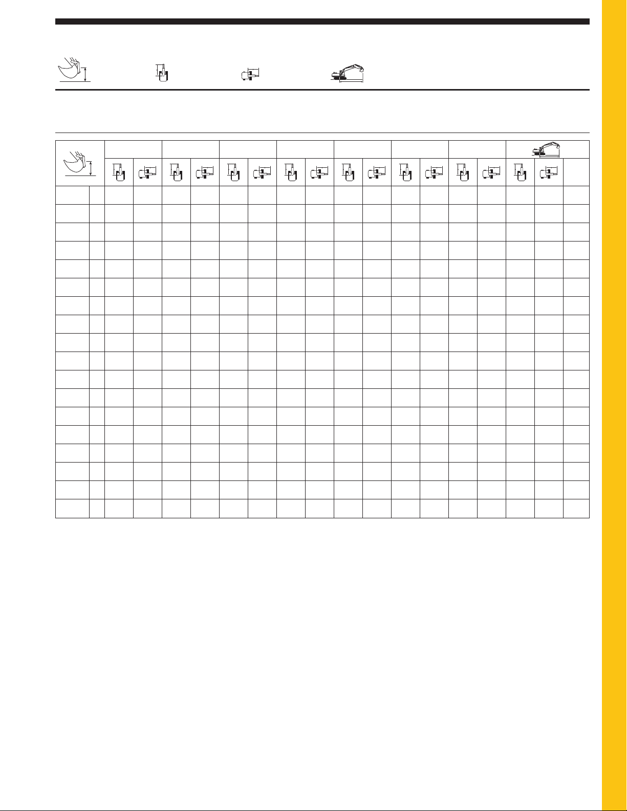
Super Long Reach Boom Lift Capacities
➤
➤
➤
➤
Load Point
Height
BOOM – 10.2 m (33'6")
STICK – 7.85 m (25'9")
Load Radius
Over Front
Load Radius
Over Side
BUCKET – 1142 mm (45")
Ditch Cleaning Bucket
291 kg (642 lb)
Load at Maximum
Reach – Bucket Curled
SHOES – 800 mm (32") triple grouser
UNDERCARRIAGE – Long
HEAVY LIFT – On
6.0 m (20.0 ft) 7.5 m (25.0 ft) 9.0 m (30.0 ft) 10.5 m (35.0 ft) 12.0 m (40.0 ft) 13.5 m (45.0 ft) 15.0 m (50.0 ft)
12.0 m kg *980 *980 15.24
40.0 ft lb *2,200 *2,200 49.56
10.5 m kg *1630 *1630 *1710 *1710 *930 *930 16.16
35.0 ft lb *3,650 *3,650 *3,550 *3,550 *2,050 *2,050 52.72
9.0 m kg *1610 *1610 *1680 *1680 *900 *900 16.89
30.0 ft lb *3,600 *3,600 *3,700 3,700 *2,000 *2,000 55.21
7.5 m kg *1730 *1730 *1710 *1710 *870 *870 17.01
25.0 ft lb *3,750 *3,750 *3,800 3,650 *1,920 *1,920 57.11
6.0 m kg *1820 *1820 *1790 1680 *870 *870 17.62
20.0 ft lb *4,000 *4,000 *3,900 3,550 *1,930 *1,930 58.32
4.5 m kg *2070 *2070 *1960 *1960 *1890 1600 *880 *880 17.99
15.0 ft lb *4,500 *4,500 *4,300 *4,300 *4,150 3,400 *1,940 *1,940 59.02
3.0 m kg *2860 *2860 *2530 *2530 *2300 *2300 *2130 1910 *2010 1510 *910 880 18.22
10.0 ft lb *6,200 *6,200 *5,500 *5,500 *5,000 *5,000 *4,650 4,100 *4,400 3,200 *2,002 1,940 59.76
1.5 m kg *5290 *5290 *4060 *4060 *3330 *3330 *2860 2820 *2540 2230 *2300 1780 *2140 1420 *930 860 18.32
5.0 ft lb *11,400 *11,400 *8,750 *8,750 *7,200 *7,200 *6,200 6,050 *5,500 4,800 *5,000 3,800 *4,650 3,000 *2,050 1,900 59.91
Ground kg *6250 5670 *4690 4220 *3770 3260 *3180 2580 *2770 2060 *2480 1660 *2270 1330 *950 850 18.28
Line lb *13,500 12,250 *10,150 9,100 *8,150 7,050 *6,900 5,550 *6,000 4,400 *5,400 3,550 *4,950 2,850 *2,090 1,880 59.83
–1.5 m kg *6950 5140 *5220 3830 *4160 2980 *3470 2370 *2990 1910 *2650 1550 2240 1260 *1000 860 18.12
–5.0 ft lb *15,050 11,100 *11,300 8,250 *9,000 6,400 *7,500 5,100 *6,500 4,100 5,750 3,300 4,800 2,700 *2,200 1,900 59.58
–3.0 m kg *7400 4820 *5600 3570 *4470 2770 *3710 2210 3090 1790 2580 1460 2180 1200 *1080 890 17.82
–10.0 ft lb *16,050 10,400 *12,150 7,700 *9,700 5,950 *8,050 4,750 6,650 3,850 5,550 3,100 4,650 2,550 *2,380 1,960 58.40
–4.5 m kg *7650 4670 *5850 3410 4550 2640 3650 2100 3000 1710 2520 1400 2140 1160 *1180 960 17.36
–15.0 ft lb *16,550 10,050 *12,700 7,350 9,800 5,650 7,850 4,500 6,450 3,650 5,400 3,000 4,600 2,500 *2,600 2,060 56.90
–6.0 m kg *7710 4630 5840 3340 4480 2570 3590 2040 2950 1660 2480 1370 2130 1150 *1310 1090 16.74
–20.0 ft lb *16,700 9,950 12,550 7,200 9,650 5,500 7,700 4,400 6,350 3,550 5,350 2,950 4,600 2,450 *2,920 2,130 54.87
–7.5 m kg *7600 4670 5850 3350 4460 2550 3570 2030 2950 1650 2490 1380 2160 1180 *1500 1230 15.94
–25.0 ft lb *16,450 10,050 12,600 7,200 9,600 5,500 7,700 4,350 6,350 3,550 5,400 2,950 *3,310 2,710 52.22
–9.0 m kg *7310 4800 *5780 3420 4510 2600 3610 2060 2990 1690 2550 1440 *1770 1480 14.92
–30.0 ft lb *15,800 10,350 *12,450 7,350 9,750 5,600 7,800 4,450 6,450 3,650 5,550 3,150 *3,900 3,260 46.02
–10.5 m kg *6800 4990 *5420 3550 *4430 2710 *3670 2160 *3010 1800 *2200 1870 13.63
–35.0 ft lb *14,600 10,800 *11,600 7,700 *9,500 5,850 *7,800 4,700 *6,350 3,950 *4,850 4,190 44.77
–12.0 m kg *5970 5280 *4780 3770 *3870 2890 *3090 2350 *2590 *1930 11.96
–40.0 ft lb *12,650 11,450 *10,100 8,200 *8,150 6,300 *6,350 5,150 *5,710 4,310 38.77
–12.0 m kg *4620 *4620 *3630 *3630 *2700 *2700
–40.0 ft lb
* Limited by hydraulic capacity rather than tipping load. The above loads are in compliance with SAE hydraulic excavator lift capacity rating standard J1097.
They do not exceed 87% of hydraulic lifting capacity or 75% of tipping capacity. Weight of all lifting accessories must be deducted from the above
lifting capacities.
Always refer to the appropriate Operation and Maintenance Manual for specific product information.
m
ft
Page 28
Mass Boom Lift Capacities
➤
➤
➤
➤
➤
➤
➤
➤
➤
➤
➤
➤
➤
➤
➤
➤
➤
➤
➤
➤
➤
➤
➤
➤
➤
➤
➤
➤
28
324D L Hydraulic Excavator specifications
Load Point
Height
Load Radius
Over Front
BOOM – 5.3 m (17'5")
M2.5DB STICK – 2.5 m (8'2")
Load Radius
Over Side
Load at Maximum
Reach – Bucket Curled
BUCKET – 1219 mm (48") HD
with General Duty Tips
1441 kg (3,177 lb)
SHOES – 800 mm (32") triple grouser
UNDERCARRIAGE – Long
HEAVY LIFT – On
Load at Maximum
Reach – Bucket Extended
3.0 m (10.0 ft) 4.5 m (15.0 ft) 6.0 m (20.0 ft) 7.5 m (25.0 ft)
mm
ft ft
7.5 m kg *5600 *5600 *5350 5040 6.42 *3610 *3610 7.81
25 ft lb *12,500 12,400 *11,900 11,500 20.7 *8,000 *8,000 25.3
6.0 m kg *5740 *5740 *5110 3680 *5040 3660 7.51 *3490 2880 8.81
20 ft lb *12,550 *12,550 *11,260 8,110 *11,150 8,200 24.5 *7,700 6,450 28.8
4.5 m kg *7980 *7980 *6550 5760 *5840 3700 5050 3020 8.19 *3540 2420 9.39
15 ft lb *17,150 *17,150 *14,200 12,350 *12,750 7,900 *11,150 6,700 26.8 *7,800 5,350 30.8
3.0 m kg *10 420 8920 *7700 5470 5950 3600 4600 2700 8.54 *3710 2200 9.64
10 ft lb *22,400 19,200 *16,650 11,750 12,750 7,700 10,150 5,950 28.0 *8,150 4,850 31.6
1.5 m kg *12 500 8220 8570 5160 5800 3470 4460 2590 8.63 3760 2160 9.6
5 ft lb *26,950 17,700 18,400 11,100 12,450 7,400 9,850 5,700 28.3 8,300 4,750 31.5
Ground kg *13 420 7850 8320 4940 5680 3360 4600 2670 8.44 3960 2280 9.26
Line lb *29,050 16,850 17,850 10,600 12,200 7,200 10,150 5,900 27.7 8,750 5,050 30.4
–1.5 m kg *8390 *8390 *13 310 7780 8220 4850 5640 3320 5090 2980 7.97 *4040 2640 8.59
–5 ft lb *19,250 *19,250 *28,850 16,700 17,650 10,400 12,100 7,100 11,250 6,600 26.1 *8,850 5,850 28.1
–3.0 m kg *15 790 *15 790 *12 250 7900 8270 4900 6190 3680 7.15 *2680 *2680 7.49
–10 ft lb *36,150 35,400 *26,450 16,950 17,750 10,550 13,750 8,200 23.3 *5,800 *5,800 24.4
–4.5 m kg *13 610 *13 610 *9780 8200
–15 ft lb *29,150 *29,150 *20,850 17,650
* Limited by hydraulic capacity rather than tipping load. The above loads are in compliance with SAE hydraulic excavator lift capacity rating standard J1097.
They do not exceed 87% of hydraulic lifting capacity or 75% of tipping capacity. Weight of all lifting accessories must be deducted from the above
lifting capacities.
Always refer to the appropriate Operation and Maintenance Manual for specific product information.
Page 29

29
324D L Hydraulic Excavator specifications
Standard Equipment
Standard equipment may vary. Consult your Caterpillar®dealer for details.
Electrical
65 Ampere alternator
Base machine light (frame)
Lights, cab mounted (Two)
Horn
Pre-start monitoring system – checks for low fluids
(engine oil, coolant, hydraulic oil) prior to starting
machine
Operator Environment
Air conditioner, heater, defroster with automatic
climate control
AM/FM Radio with antenna and 2 speakers
Ashtray with 24 volt lighter
Beverage/cup holder
Bolt-on Falling object Guarding System (FOGS) capability
Cab Glass
Openable and retractable two-piece front windshield
Skylight, pop-up, polycarbonate
Coat hook
Floor mat
Instrument panel and gauges
Joysticks, console mounted, pilot operated
Light, interior
Literature compartment
Monitor, full graphic color display
Neutral lever (lock out) for all controls
Polycarbonate side windows
Positive filtered ventilation
Pressurized cab
Seat, suspension, with high back and head rest
Seat belt, retractable – 76 mm (3 in)
Storage compartment suitable for lunch box cooler
Sun shade (for skylight)
Travel control pedals with removable hand levers
Windshield wiper and washer (upper and lower)
Engine/Power Train
C7 with ACERT™ Technology
Air intake heater
Air-to-air aftercooler (ATAAC)
24 volt electric start
Hydraulic electronic unit injectors (HEUI)
2300 m (7,500 ft) altitude capability without derate
Automatic engine speed control with one touch low idle
Cooling
Protection of 43° C (110° F) to –18° C (0° F) at
50% concentration
Electric priming pump
Straight line travel
Two-speed auto-shift travel
Water separator in fuel line
Water level indicator for water separator
Undercarriage
Grease lubricated track
Hydraulic track adjusters
Idler and center section track guards
Other Standard Equipment
Automatic swing parking brake
Auxiliary hydraulic valve
Capability of stackable valves (max of 3) for main valve
Capability of auxiliary circuit
Counterweight with lifting eyes
Door locks, cap locks and Caterpillar
®
one key
security system
Fine swing control
Fully pressurized hydraulic system
Heavy lift
Mirrors (frame-right, cab left)
S•O•SSMquick sampling valves for engine and hydraulic oil
Travel alarm
Product Link PL321SR
Page 30

Optional Equipment
Optional equipment may vary. Consult your Caterpillar®dealer for details.
Engine/Power Train
High ambient cooling
For conditions up to 52° C (125° F)
Prefilter, air
Starting, Cold weather package
Two additional maintenance free batteries
High capacity starter motor
Heavy-duty cable
Jump-start receptacle
Ether aid
Block heater
Undercarriage
Track shoes
600 mm (24 in) double grouser
790 mm (31 in) triple grouser
800 mm (32 in) Heavy-duty triple grouser
Heavy-duty rollers
Auxiliary Hydraulics
Hammer Circuit
For single function (1 way/2 pump) hydraulic tools
Thumb Circuit
For double function (2 way/1 pump) hydraulic tools
Tool Control System
For single or double function, (1 or 2 way, 1 or 2 pump)
hydraulic tools
Joysticks with additional switches
Program up to 10 tools in memory
Capability of adding medium pressure
Medium pressure circuit for tools requiring
medium pressure
Hydraulic pin grabber quick coupler and controller
Lines for booms and sticks
Work Tools
Wide offering of buckets, tips and sidecutters
Front Linkage
Booms
Reach 5.9 m (19 ft 4 in)
Mass 5.3 m (17 ft 5 in)
Super Long Reach 10.2 m (33 ft 6 in)
Sticks
Reach 3.6 m (11 ft 10 in)
Reach 2.95 m (9 ft 8 in)
Reach 2.5 m (8 ft 2 in)
Mass 2.5 m (8 ft 2 in)
Bucket Linkage
B1 Family
CB1 Family
DB Family
Boom Lowering Control Device
Electrical
Machine Security System
Power supply (12V-10 AMP)
Guarding
Falling Object Guarding System (FOGS)
Front windshield guard
Full length, wire mesh
Heavy-duty bottom guards
Rubber bumpers
Track guiding guards
Sprocket end, idler end guard
Two-piece full length (center guard removed)
Vandalism guards
Operator Environment
Hand control pattern changer (ISO-SAE)
Rear window, secondary exit
Sunscreen – roller type
Seat, high back with air suspension and heater
Third pedal, straight travel
30
324D L Hydraulic Excavator specifications
Page 31

31
324D L Hydraulic Excavator specifications
Notes
Page 32

For more complete information on Cat products, dealer services,
and industry solutions, visit us on the web at www.cat.com
© 2009 Caterpillar
All Rights Reserved
Printed in U.S.A.
Materials and specifications are subject to change without notice.
Featured machines in photos may include additional equipment.
See your Caterpillar dealer for available options.
CAT, CATERPILLAR, ACERT, SAFETY.CAT.COM, their respective logos, “Caterpillar Yellow”
and the POWER EDGE trade dress, as well as corporate and product identity used
herein, are trademarks of Caterpillar and may not be used without permission.
AEHQ5663-03 (2-09)
Replaces AEHQ5663-02
NACD, LACD
324D L Hydraulic Excavator
R
 Loading...