

Page 1
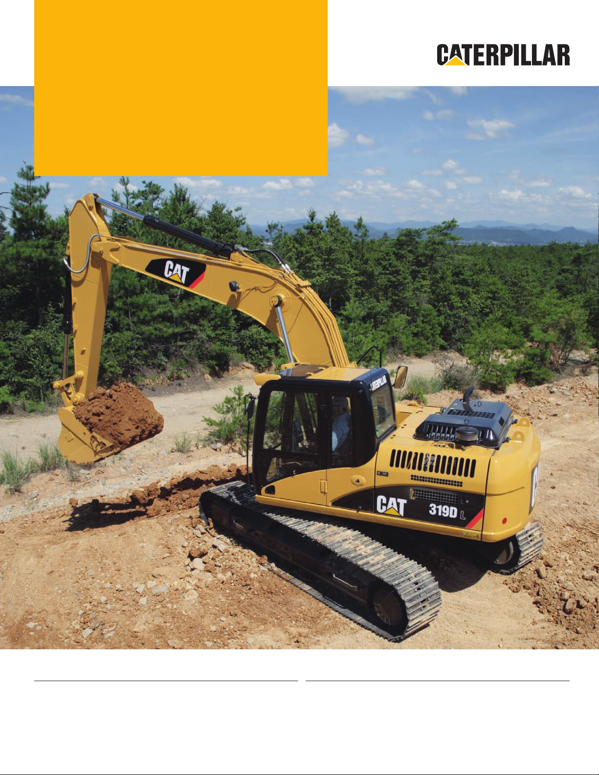
319D L/
®
319D LN
Hydraulic Excavators
Engine
Engine Model Cat® C4.2 engine ACERT™
Gross Power 98 kW 131 hp
Net Power (SAE J1349) 93 kW 125 hp
Weights
Operating Weight – Long Narrow
Undercarriage
Operating Weight – Long Undercarriage 19 900 kg 43,872 lb
19 480 kg 42,946 lb
Page 2
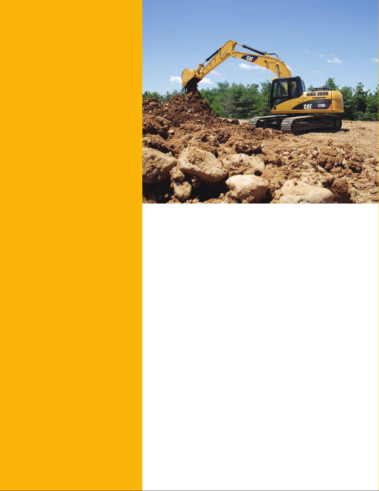
319D L/319D LN Features
Comfortable Operator Station
Spacious and quiet, this world class cab lets the
operator focus on performance and production.
Industry Leading Performance
The 319D L/319D LN with a Cat® C4.2 ACERT™
engine and overall system efficiency delivers
industry-leading productivity.
Maximum Versatility
Easily configure and operate a large variety of
work tools with the Cat Tool Control System.
Proven Reliability
Caterpillar® design and manufacturing techniques
provide maximum uptime with outstanding
durability and service life.
Low Emissions Engine
Do more work using less fuel with the Cat
C4.2 ACERT engine. It meets U.S. EPA Tier 3
and EU Stage IIIA emission standards while
maintaining the power and performance
expected from Caterpillar.
Long Narrow (LN) Undercarriage
The long narrow version of the undercarriage
allows for permit-free transportability in most
areas since it meets the 2590 mm (8 ft 6 in)
transport width limit with 600 mm (24 in)
track shoes.
Contents
Operator Station ..................................................3
Engine ...................................................................4
Hydraulics ............................................................5
Undercarriage and Structures .........................6
Front Linkage .......................................................6
Versatility ..............................................................7
Serviceability .......................................................8
Customer Support ...............................................9
319D L/319D LN Hydraulic Excavator
Specifications ....................................................10
319D L/319D LN Standard Equipment ............11
319D L/319D LN Optional Equipment ..............11
Achieve high productivity and lower operating costs
with the Cat® 319D L/319D LN Hydraulic Excavator.
Unmatched versatility, improved controllability, easy
operation and a comfortable, redesigned operator station
help make the 319D an industry-leading performer.
2
Page 3
Operator Station
New levels of comfort, visibility and operation
Cab
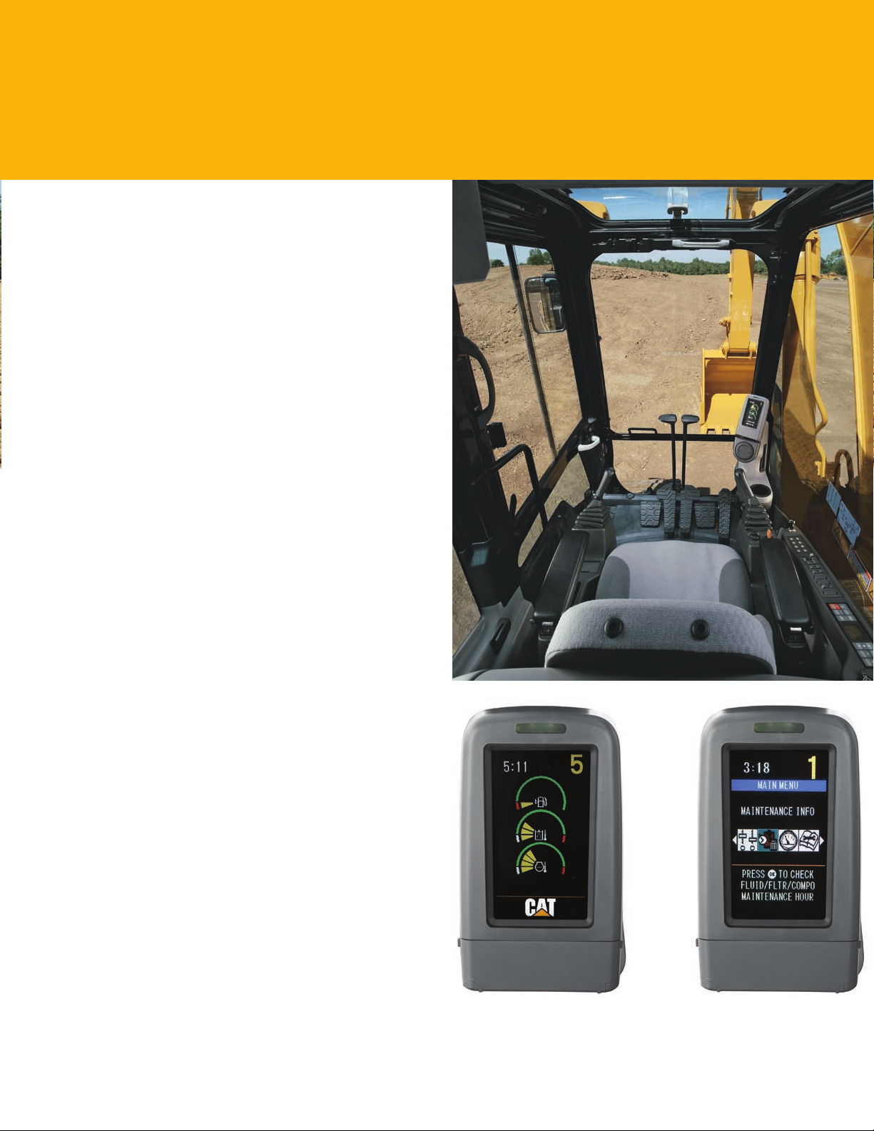
Experience a spacious, quiet and comfortable operator
station. The cab is pressurized to reduce the amount of
dust that enters the cab, keeping the operator comfortable
the entire shift, while assuring high productivity during long
work hours.
The comfortable seat adjusts to suit the operator’s
•
size and weight. Available as an option is a heated,
air suspension seat.
Standard air conditioning with automatic climate
•
control adjusts temperature and airow.
Low effort joystick controls are designed to match the
•
operator’s natural wrist and arm position. Joysticks can
be operated with arms on the armrest. The horizontal
and vertical strokes are designed to reduce fatigue.
Prestart Check and Monitor Display
Prior to starting the machine, the system checks for low
engine oil, hydraulic oil and engine coolant uid levels and
warns the operator through a color Liquid Display (LCD)
monitor. The LCD monitor displays vital operating and
performance information in 27 different languages for
operator convenience.
Cab Exterior
The 319D L/319D LN provide a new cab design that allows
the Falling Object Guard System (FOGS) to be bolted
directly to the cab, at the factory or in the eld, enabling
the machine to meet specications and job site requirements.
The cab shell is attached to the frame with viscous rubber cab
mounts that dampen vibrations and sound levels to enhance
operator comfort.
Machine Security System
An optional Machine Security System (MSS) utilizes
a programmable key, deterring theft, vandalism and
unauthorized usage. MSS uses electronically coded keys
selected by the customer to limit usage by individuals or
time parameters.
3
Page 4
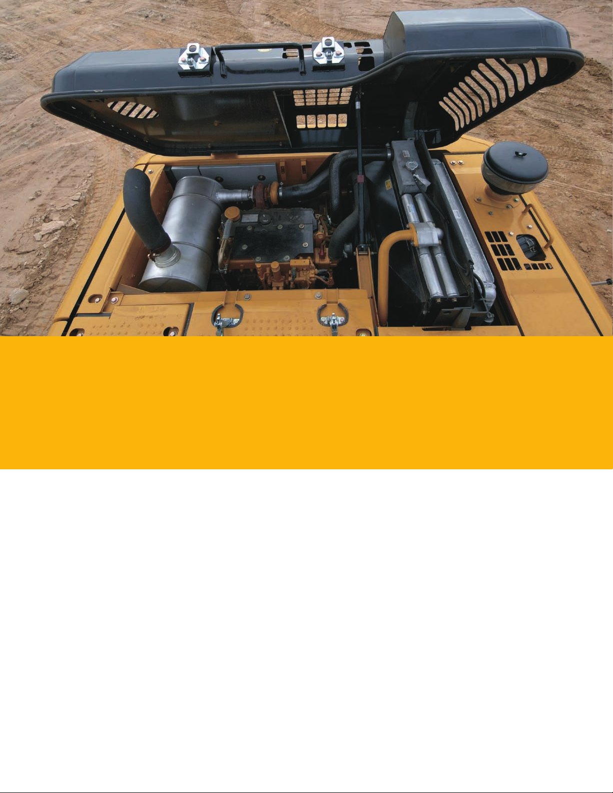
Engine
Clean, quiet operation with reduced fuel consumption.
The Cat C4.2 engine with ACERT Technology optimizes performance and meets U.S. EPA Tier 3 and EU Stage IIIA
regulations. In conjunction with integrated electronics, ACERT Technology reduces emissions during the combustion process
by using advanced technology in the air and fuel system. The Cat C4.2 engine delivers exceptional power, allowing more
hydraulic pressure to drive productivity and reduce your cost per tone of material moved.
Automatic Engine Control and Fuel Delivery
A two-stage control and one-touch low idle button maximizes fuel efciency and reduces sound levels. Fuel delivery is managed
by the ADEM™ A4 Engine Controller for the best performance per liter (gallon) of fuel used. Flexible fuel mapping allows the
engine to respond quickly to varying application needs. Electronic controls govern the fuel injection system. Multiple injection
fuel delivery involves a high level of precision and by precisely shaping the combustion cycle, lowers combustion chamber
temperatures, generates fewer emissions and optimizes fuel combustion. This means more work output for your fuel cost.
Crankshaft and Pistons
A forged, one-piece, induction hardened crankshaft enhances balance, decreases vibration and improves abrasion resistance.
Heat resistant, aluminum alloy pistons have a short compression height for greater efciency and longer life.
Economy Mode
Accessible through the in-cab monitor, economy mode allows you to balance the demands of performance and fuel economy
while maintaining the breakout forces and lift capacity enjoyed at standard power.
4
Page 5
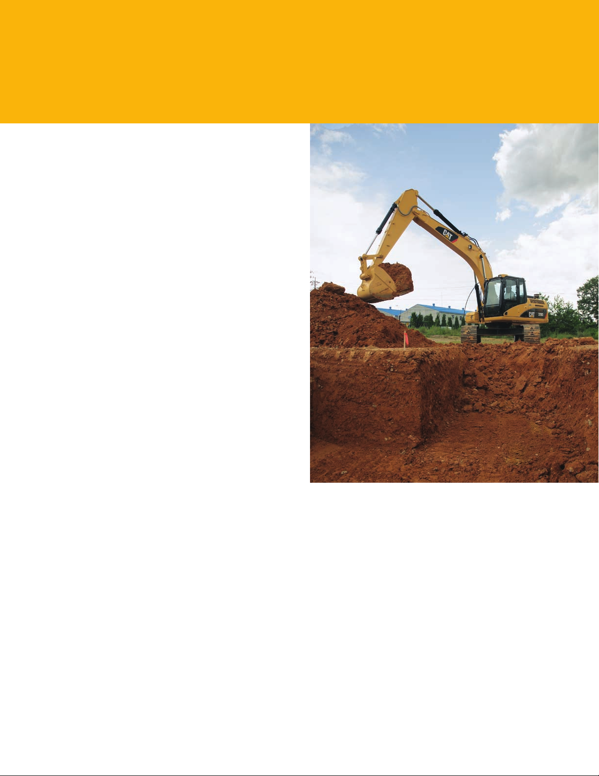
Hydraulics
High efficiency and performance with low effort and precise control.
Outstanding Performance
With two percent more hydraulic pressure for additional lift
and breakout forces, the 319D L/319D LN hydraulic system
is designed for high efciency and performance. Auxiliary
hydraulic and electrical lines are routed to the boom foot
as standard, making installation of hydraulic circuits much
easier. This compact design utilizes shorter tubes and lines,
reducing friction and pressure drops, resulting in a more
efcient use of power.
Hydraulic snubbers at the rod end of the boom cylinders
•
and both ends of the stick cylinders cushion shock,
reduce sound and increase cylinder life.
Flow is reduced to a minimum when controls are
•
in neutral to reduce fuel consumption and extend
component life.
Hydraulic Cross-Sensing System uses two hydraulic
•
pumps up to 100 percent of available hydraulic power
under all operating conditions, improving productivity
with faster implement speeds and quicker, stronger
pivot turns.
A longer undercarriage (versus 318C L/318C LN) and
•
heavy counterweight option that provides additional
300 kg (600 lb) provide increased stability to better
utilize breakout forces and hydraulic lifting capability.
Boom and Stick Regeneration Circuit
The boom and stick electronic regeneration circuit saves
energy during boom-down and stick-in operation, increasing
efciency and lowering operating costs.
Easy Operation
Work mode and power mode switches have been eliminated
making full power available at all times. Operators do not
need to learn different modes, an automatic boom and swing
priority function automatically selects the best mode based
on joystick movement.
5
Page 6
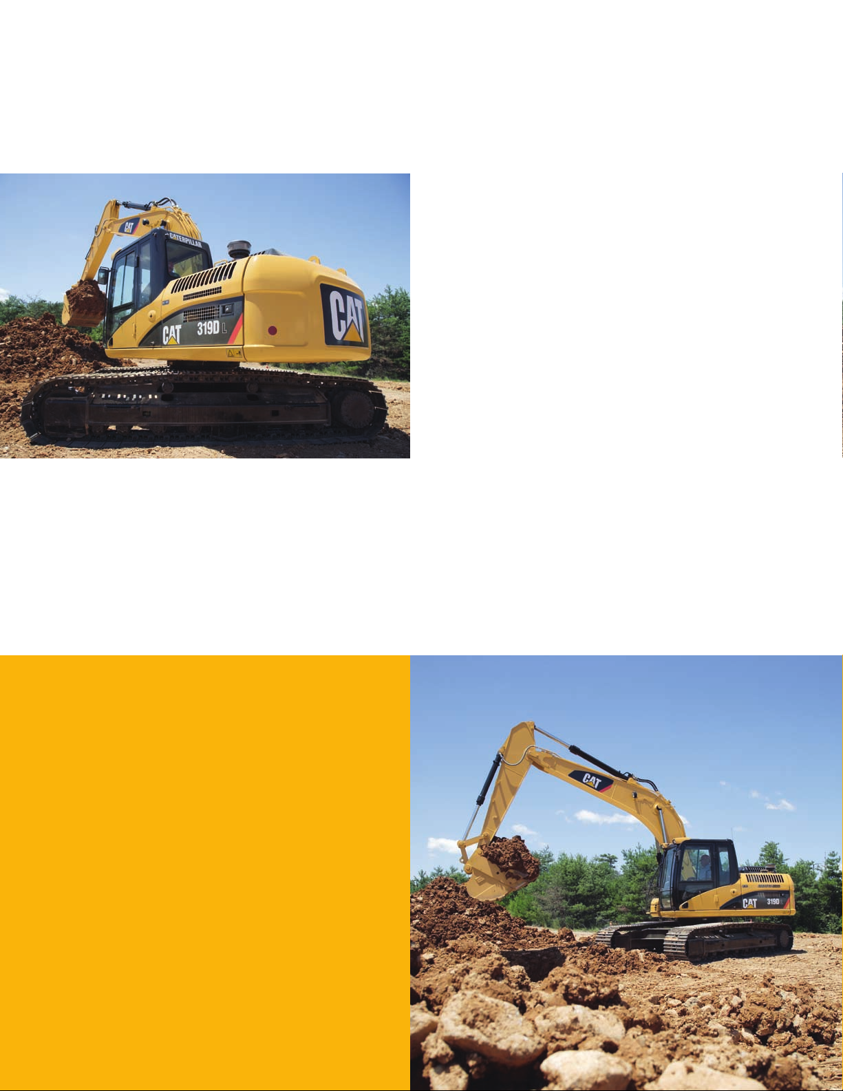
Undercarriage and Structures
Excellent stability and maneuverability.
Caterpillar uses advanced engineering and software to
analyze all structures, creating a durable, reliable machine
for the toughest applications. More than 70 percent of
the structural welds are robotic and achieve additional
penetration over manual welds. These structural components
and undercarriage are the backbone of the machine’s durability.
Carbody Design
X-shaped, box section carbody provides excellent resistance
to torsional bending. Robot-welded track roller frames are
press-formed, pentagonal units that deliver exceptional
strength and service life. Integral to the track roller frame
are the standard idler and center guards, which help maintain
track alignment when traveling or working on slopes.
Grease Lubricated Track
Track links are assembled and sealed with grease to decrease
wear and increase life by as much as 25 percent, when
compared to dry seal undercarriages.
Front Linkage
Performance, reliability and durability.
Built for performance and long service life, Cat booms
and sticks are welded, box-section structures with thick
multi-plate high strength steel fabrications. The 319D L/
319D LN offers one boom with three different stick options.
Sticks
The three stick options provide exibility to optimize and
match reach, dig depth and lifting and digging forces to
the application.
Travel Motors
Travel motors with automatic speed selection let the 319D L/
319D LN automatically change up and down from high and
low speeds in a smooth, controlled manner.
Boom
The boom is designed for maximum digging capability
and is robotic welded to ensure consistent quality.
This allows excellent all-around versatility and a large
working envelope.
6
Page 7
Versatility
Do more with less.
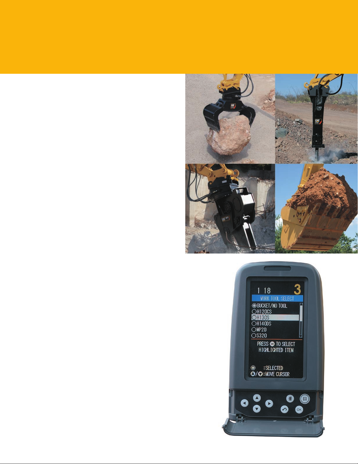
Work Tools
Caterpillar offers a variety of work tools including Hammers,
Thumbs, Grapples, Multi-Processors, Shears, Pulverizers,
Vibratory Compactors and Rippers to t your needs. A wide
range of buckets are also available to optimize machine
performance.
Auxiliary hydraulic and electrical lines are routed to the
boom foot as standard for easier retrot of auxiliary
hydraulic circuits, therefore reducing time, parts and cost
required to add a work tool.
Hydraulic Pin Grabber Coupler
An optional hydraulic pin grabber coupler is available to pick
up a wide variety of buckets and work tools without having
to leave the cab, thus maximizing productivity.
Cat K-Series™ Tooth System
The Cat K-Series Tooth System provides more wear material,
a longer tip and adapter life, a one-piece vertical drive
retainer, reliable tip retention and easy installation and
removal, improving performance and penetration.
Enhanced Systems
Work tool functionality has increased the versatility of the
machine with the enhancement of the following:
Optional Combined Function Circuit enables one or
•
two pump ow in one or two directions. This single
hydraulic circuit runs tools such as a hydraulic thumb,
hammer, plate compactor, tilting bucket and auger.
Tool Control System stores up to 10 different tool
•
settings through the in-cab monitor. Cat Work Tools
are selectable with preset ows and pressures.
Optional Priority Flow System offers all the advantages
•
of the Combined Function Circuit plus true priority ow
for hydraulic work tools such as rotary mowers.
Transportability
The 319D L/319D LN (depending on overall machine
conguration) can typically meet federal gross weight
transport limits for truck, trailer and machine combined.
The Long Narrow (LN) undercarriage provides additional
exibility to meet the transport width limit of 2590 mm
(8 ft 6 in) when equipped with 600 mm (24 in) track shoes,
which is critical in some areas. This all adds up to more
permit-free transportability, lowering operating costs and
allowing frequent movement of the machine with less hassle.
7
Page 8
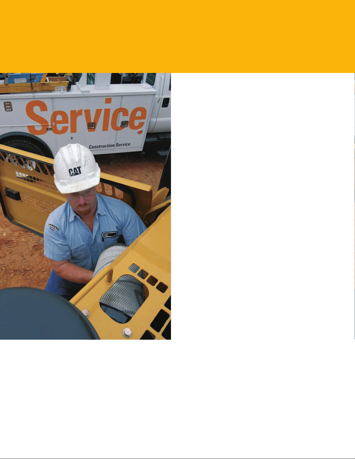
Serviceability
Simplified service and maintenance saves time and money.
Designed with the service technician in mind, many service
locations are at ground level so critical maintenance can be
done quickly and efciently. Longer maintenance intervals
reduce cost and increase machine availability.
LCD monitor has the capability to memorize working
•
hours for lters, uids, components and work tools.
Working time histories and recommended change
intervals can be displayed.
Engine oil level check, fuel lters and priming pump are
•
conveniently located on the front of the engine for easy
maintenance.
An optional electronic fuel water sensor is available
•
to alert the operator when the water level is high.
Product Link assists with eet management by tracking
•
hours, location and product health.
New anti-skid plates over the top of the storage box
•
and upper structure help prevent slipping and mud from
falling into the upper structure.
Sampling Ports
Equipped with S·O·SSM sampling ports and test ports for
hydraulics, engine oil and coolant for quick diagnostics.
A test connection for the Cat Electronic Technician (Cat ET)
service tool is now located in the cab.
Air Cleaner
A double-layered lter core in the radial seal air lter gives
more efcient ltration. A warning is displayed on the monitor
when dust accumulates above a preset level. This lter is
conveniently located in the compartment behind the cab.
An optional pre-cleaner is also available to extend lter life
and reduce maintenance costs.
Capsule Filter
Capsule-type, hydraulic return lter is accessible from
outside the tank and prevents contaminants from entering
the system when changing the hydraulic oil.
Radiator Compartment
Horizontal air conditioner condenser swings out for easy
cleaning. Removable screens are located in front of the radiator
and hydraulic cooler, reducing cleaning time and effort.
8
Page 9
Customer Support
Unmatched support makes the difference.
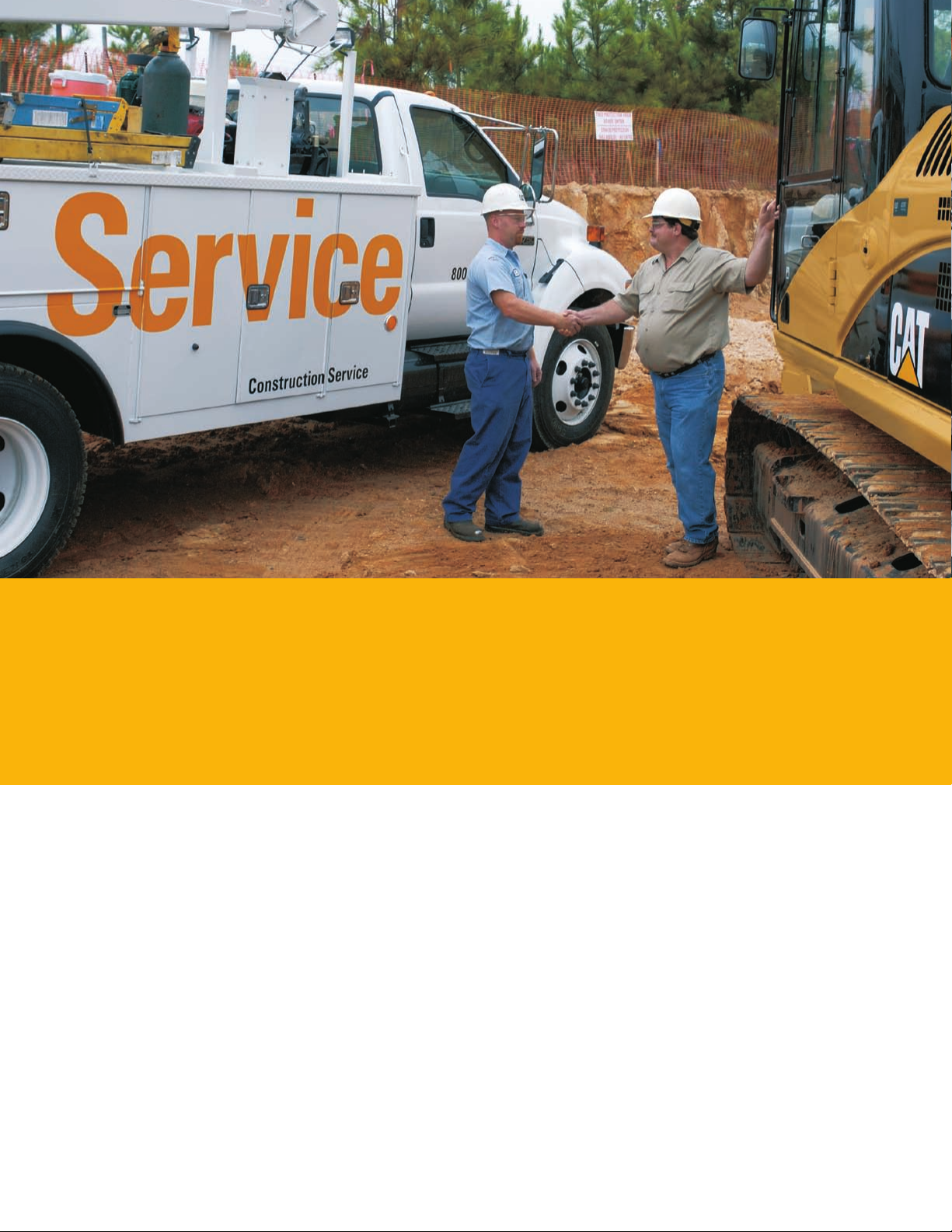
Your Cat dealer is ready to assist you with your purchase decision and everything after.
Make detailed comparisons of the machines you are considering before you buy – with estimates of component life,
•
preventive maintenance and the true cost of production.
Customize the machine that is right for you using the Build and Quote application on your dealer’s web site or www.cat.com.
•
Get the latest training literature and trained staff.
•
Repair option programs guarantee the cost of repairs up front.
•
Nearly all parts are available at dealer parts counters.
•
Financing packages are exible to meet your needs.
•
Your Cat dealer can evaluate the cost involved in repairing, rebuilding and replacing your machine, so you can make the
•
right choice.
SAFETY.CAT.COM™
9
Page 10
319D L/319D LN Hydraulic Excavator Specifications
Engine
Engine Model Cat® C4.2 engine
ACERT™
Gross Power 98 kW 131 hp
Net Power
(SAE J1349)
ISO 9249 93 kW 125 hp
Bore 102 mm 4 in
Stroke 130 mm 5.1 in
Displacement 4.2 L 259 in
The 319D L/319D LN meets U.S. EPA
•
Tier 3 and EU Stage IIIA Directive/97/68/
EC emission requirements.
Net power advertised is the power available
•
at the ywheel when the engine is equipped
with fan, air cleaner, mufer and alternator.
No engine power derating required below
•
2300 m (7,500 ft) altitude.
93 kW 125 hp
3
Weights
Operating Weight –
Long Undercarriage
Operating Weight
– Long Narrow
Undercarriage
Long undercarriage: 700 mm (28 in) track
•
shoes, 3.2 m (10 ft 6 in) stick, 0.77 m3
(1.0 yd3) bucket.
Long Narrow undercarriage: 600 mm
•
(24 in) track shoes, 3.2 m (6 ft 10 in) stick
and 0.77 m3 (1.0 yd3) bucket.
19 900 kg 43,872 lb
19 480 kg 42,946 lb
Swing Mechanism
Swing Torque 50.7 kN·m 37,394 lb ft
Swing Speed 11.1 rpm
Drive
Maximum
Travel Speed
Maximum
Drawbar Pull
4.8 km/h 3 mph
206.7 kN 46,466 lb
Hydraulic System
Main Implement
System – Maximum
Flow (2x)
Maximum Pressure
– Implements
Maximum Pressure
– Travel
Maximum Pressure
– Swing
Pilot System
– Maximum Flow
Pilot System
– Maximum Pressure
Boom Cylinder
– Bore
Boom Cylinder
– Stroke
Stick Cylinder – Bore 130 mm 5.1 in
Stick Cylinder
– Stroke
Bucket Cylinder
– Bore
Bucket Cylinder
– Stroke
176 L/min 46.5
gal/min
35 000 kPa 5,076 psi
35 000 kPa 5,076 psi
23 000 kPa 3,336 psi
26.7 L/min 7.1 gal/min
4120 kPa 598 psi
120 mm 4.7 in
1193 mm 47 in
1364 mm 53.7 in
110 mm 4.3 in
1048 mm 41.3 in
Service Refill Capacities
Fuel Tank 300 L 79.3 gal
Cooling System 22 L 5.8 gal
Engine Oil 19.5 L 5.2 gal
Swing Drive (each) 8 L 2.1 gal
Final Drive (Each) 10 L 2.6 gal
Hydraulic System
(Including Tank)
Hydraulic Tank 106 L 28 gal
190 L 50.2 gal
Standards
Cab/FOGS SAE J1356
FEB 88/ISO 10262
Sound Performance
Performance ANSI/SAE J1166
OCT 98
When properly installed and maintained,
•
the cab offered by Caterpillar, when tested
with doors and windows closed according
to ANSI/SAE J1166 OCT 98, meets OSHA
and MSHA requirements for operator
sound exposure limits in effect at time of
manufacture.
Hearing protection may be needed when
•
operating with an open operator station
and cab (when not properly maintained or
doors/windows/open) for extended periods
or in noisy environment.
10
Page 11
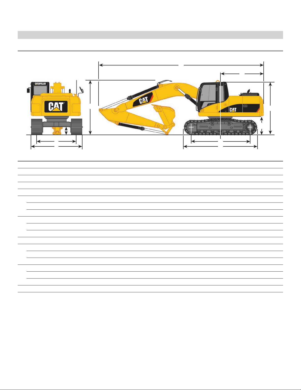
Boom Options Reach Reach Reach
Stick Options 2.25 m (7'5") 2.7 m (8'10") 3.2 m (10'6")
1 Shipping Height 3120 mm (10'2") 3080 mm (10'1") 3530 mm (11'7")
2 Shipping Length 8820 mm (28'11") 8780 mm (28'10") 8760 mm (28'9")
3 Tail Swing Radius 2500 mm (8'2") 2500 mm (8'2") 2500 mm (8'2")
4 Length to Center of Rollers
319D L 3650 mm (12'0") 3650 mm (12'0") 3650 mm (12'0")
319D LN 3650 mm (12'0") 3650 mm (12'0") 3650 mm (12'0")
5 Track Length
319D L 4450 mm (14'7") 4450 mm (14'7") 4450 mm (14'7")
319D LN 4450 mm (14'7") 4450 mm (14'7") 4450 mm (14'7")
6 Ground Clearance 440 mm (1'5") 440 mm (1'5") 440 mm (1'5")
7 Track Gauge
319D L 2200 mm (7'3") 2200 mm (7'3") 2200 mm (7'3")
319D LN 1990 mm (6'6") 1990 mm (6'6") 1990 mm (6'6")
8 Transport Width 600 mm (24") Shoes 700 mm (28") Shoes 790 mm (31") Shoes
319D L 2800 mm (9'2") 2900 mm (9'6") 2990 mm (9'10")
319D LN 2595 mm (8'6")
9 Cab Height 2870 mm (9'5") 2870 mm (9'5") 2870 mm (9'5")
10 Counterweight Clearance 1030 mm (3'5")* 1030 mm (3'5")* 1030 mm (3'5")*
* Includes lug height
Dimensions
All dimensions are approximate.
6
8
7
1
9
2
5
4
3
10
11
Page 12

Operating Weights
Caterpillar designed and built track-type undercarriage.
Track Width Operating Weight Operating Weight Operating Weight
2.25 m (7'5")* 2.7m (8'10")* 3.2 m (10'6")*
319D L 600 mm (24") triple grouser 19 450 kg 42,880 lb 19 460 kg 42,902 lb 19 520 kg 43,034 lb
700 mm (28") triple grouser 19 830 kg 43,718 lb 19 840 kg 43,740 lb 19 900 kg 43,872 lb
790 mm (31") triple grouser 20 100 kg 44,313 lb 20 110 kg 44,335 lb 20 180 kg 44,489 lb
319D LN 500 mm (20") triple grouser 19 150 kg 42,219 lb 19 160 kg 42,241 lb 19 230 kg 42,395 lb
600 mm (24") triple grouser 19 410 kg 42,792 lb 19 420 kg 42,814 lb 19 480 kg 42,946 lb
* with SAE 0.77 m3( 1.0 yd3) and 3.6 ton counterweight.
319D L/319D LN Hydraulic Excavator Specifications
12
Page 13
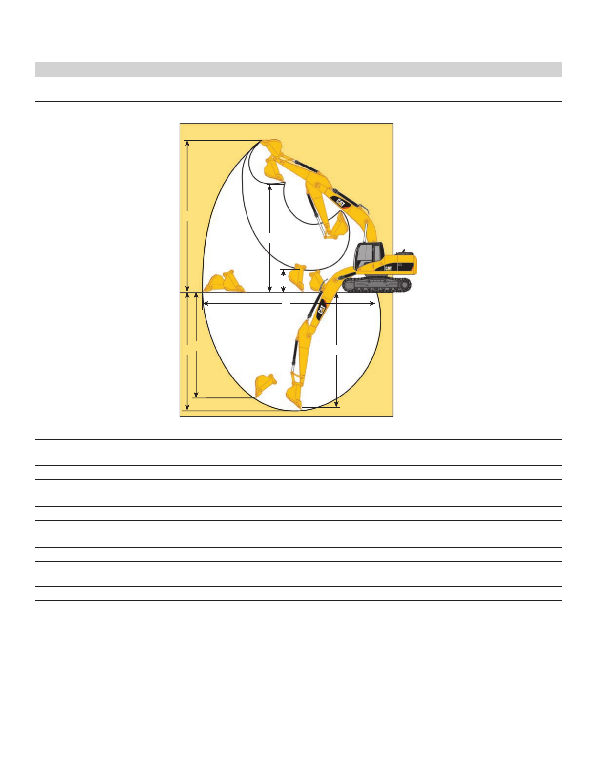
Working Ranges
All dimensions are approximate.
Boom Reach Reach Reach
5.3 m (17'5") 5.3 m (17'5") 5.3 m (17'5")
Stick 3.2 m (10'6")* 2.7 m (8'10")* 2.25 m (7'5")*
Bucket 0.77 m3(1.0 yd3) 0.77 m3(1.0 yd3) 0.77 m3(1.0 yd3)
1 Maximum Digging Depth 6890 mm (22'7") 6390 mm (21'0") 5940 mm (19'6")
2 Maximum Reach at Ground Level 9640 mm (31'8") 9110 mm (29'11") 8660 mm (28'5")
3 Maximum Cutting Height 9610 mm (31'6") 9190 mm (30'2") 8880 mm (29'2")
4 Maximum Loading Height 6840 mm (22'5") 6440 mm (21'2) 6140 mm (20'2")
5 Minimum Loading Height 1840 mm (6'0") 2330 mm (7'8") 2790 mm (9'2")
6 Maximum Depth Cut for 6720 mm (22'1") 6180 mm (20'3") 5680 mm (18'8")
2440 m (8') Level Bottom
7 Maximum Vertical Wall Digging Depth 5710 mm (18'9") 5110 mm (16'9") 4550 mm (14'11")
Minimum Front Swing Radius 3070 mm (10'1") 3120 mm (10'3") 3120 mm (10'3")
Stick Digging Force (SAE) 80.7 kN (18,142 lb) 89.9 kN (20,210 lb) 105.1 kN (23,627 lb)
Bucket Digging Force (SAE) 113.9 kN (25,606 lb) 112.3 kN (25,246 lb) 132.1 kN (29,697 lb)
* Measurements shown are for machines equipped with the 0.77 m3(1.0 yd3) buckets.
2
3
1
7
6
4
5
13
Page 14

Buckets
Buckets have tapered sides, angled corner teeth, dual radius curvature, horizontal wear strips and holes for optional side cutters.
HEAVY DUTY Recommended Maximum Material Density
Buckets Width Capacity 2.25 m (7'5") Stick 2.7 m (8'10") Stick (10'6") Stick
mm in m
3
yd
3
kg/m
3
lb/yd
3
kg/m
3
lb/yd
3
kg/m
3
lb/yd
3
239-2529 616 24 0.45 0.59 1800 3,034 1800 3,034 1800 3,034
239-2530 757 30 0.58 0.76 1800 3,034 1800 3,034 1800 3,034
239-2531 924 36 0.78 1.01 1800 3,034 1800 3,034 1500 2,528
239-2532 1052 42 0.92 1.20 1800 3,034 1500 2,528 1200 2,023
239-2533 1230 48 1.02 1.40 1500 2,528 1200 2,023 1200 2,023
Material Densities
Material kg/m3* lb/yd3** Material kg/m3* lb/yd3**
Clay, dry 1480 2,500 Gravel, pit run 1930 3,250
Clay, wet 1660 2,800 Rock/dirt, 50% 1720 2,900
Earth, dry 1510 2,550 Sand, dry 1420 2,400
Earth, wet 1600 2,700 Sand, wet 1840 3,100
Loam 1250 2,100 Sand & Clay 1600 2,700
Gravel, dry 1510 2,550 Stone, crushed 1600 2,700
Gravel, wet 2020 3,400 Top soil 950 1,600
* kilograms per loose cubic meter
** pounds per loose cubic yard
For densities of other materials see Caterpillar Performance Handbook.
319D L/319D LN Hydraulic Excavator Specifications
14
Page 15

Undercarriage
Caterpillar designed and built track-type undercarriage
Track Width Ground Pressure
3.2 m (10'6") Stick 319D L 319D LN
600 mm (24") triple grouser 40.6 kPa (5.9 psi) 40.5 kPa (5.9 psi)
700 mm (28") triple grouser 35.5 kPa (5.1 psi) –
790 mm (31") triple grouser 31.9 kPa (4.6 psi) –
Undercarriage
Caterpillar designed and built track-type undercarriage
Track Width Ground Pressure
R2.7 m (8'10") 319D L 319D LN
600 mm (24") triple grouser 40.5 kPa (5.9 psi) 40.4 kPa (5.9 psi)
700 mm (28") triple grouser 35.4 kPa (5.1 psi) –
790 mm (31") triple grouser 31.8 kPa (4.6 psi) –
Undercarriage
Caterpillar designed and built track-type undercarriage
Track Width Ground Pressure
2.25 m (7'5") Stick 319D L 319D LN
600 mm (24") triple grouser 40.5 kPa (5.9 psi) 40.4 kPa (5.9 psi)
700 mm (28") triple grouser 35.4 kPa (5.1 psi) –
790 mm (31") triple grouser 31.8 kPa (4.6 psi) –
15
Page 16
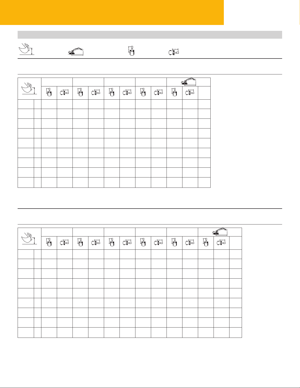
Load at
Maximum Reach
Load Point
Height
Load Radius
Over Front
Load Radius
Over Side
Reach Boom Lift Capacities
R2.7 STICK – 2.7 m (8'10")
BUCKET – 0.77 m3(1.0 yd3)
UNDERCARRIAGE – Long
SHOES – 600 mm (24") triple grouser
BOOM – Reach 5.3 m (17.4 ft)
COUNTERWEIGHT – 3.6 mt (7,940 lb)
* Indicates that the load is limited by hydraulic lifting capacity rather than tipping load. The above loads are in compliance with hydraulic excavator lift
capacity standard ISO 10567:2007. They do not exceed 87% of hydraulic lifting capacity or 75% of tipping load. Weight of all lifting accessories must be
deducted from the above lifting capacities. Lifting capacities are based on the machine standing on a firm, uniform supporting surface.
3.0 m (10.0 ft) 4.5 m (15.0 ft) 6.0 m (20.0 ft) 7.5 m (25.0 ft)
m
ft
7.5 m kg *1750 *1750 6.03
25.0 ft lb *3,700 *3,700 19.43
6.0 m kg *3700 *3700 *2300 *2300 7.09
20.0 ft lb *8,000 7,950 *5,000 *5,000 23.09
4.5 m kg *4050 3650 *3000 2350 *2350 2200 7.71
15.0 ft lb *8,800 7,750 *5,150 4,900 25.20
3.0 m kg *6200 5550 *4800 3450 *4250 2300 *2450 1950 8.10
10.0 ft lb *13,300 11,900 *10,450 7,350 *8,850 4,850 *5,350 4,250 26.54
1.5 m kg *8100 5050 *5700 3200 4200 2200 *2600 1800 8.24
5.0 ft lb *17,400 10,850 *12,300 6,900 8,950 4,650 *5,700 3,950 27.04
Ground kg *9050 4800 5950 3050 4100 2100 *2900 1850 8.08
Line lb *19,500 10,300 12,700 6,550 8,750 4,450 *6,400 4,000 26.35
–1.5 m kg *7300 *7300 *9050 4750 5850 3000 *3500 2050 7.59
–5.0 ft lb *15,750 *15,750 *19,550 10,200 12,550 6,400 *7,700 4,450 24.87
–3.0 m kg *10 550 *9750 *8300 4800 5900 3000 *4600 2550 6.74
–10.0 ft lb *23,900 *20,800 *17,900 10,300 12,600 6,500 *10,200 5,600 21.98
–4.5 m kg *8650 *8650 6250 5000 *5000 3900 5.27
–15.0 ft lb *18,400 *18,400 *13,200 10,750 *10,950 8,850 16.99
R3.2 STICK – 3.2 m (10'6")
BUCKET – 0.77 m3(1.0 yd3)
UNDERCARRIAGE – Long
SHOES – 600 mm (24") triple grouser
BOOM – Reach 5.3 m (17.4 ft)
COUNTERWEIGHT – 3.6 mt (7,940 lb)
* Indicates that the load is limited by hydraulic lifting capacity rather than tipping load. The above loads are in compliance with hydraulic excavator lift
capacity standard ISO 10567:2007. They do not exceed 87% of hydraulic lifting capacity or 75% of tipping load. Weight of all lifting accessories must be
deducted from the above lifting capacities. Lifting capacities are based on the machine standing on a firm, uniform supporting surface.
Always refer to the appropriate Operation and Maintenance Manual for specific product information.
1.5 m (5.0 ft) 3.0 m (10.0 ft) 4.5 m (15.0 ft) 6.0 m (20.0 ft) 7.5 m (25.0 ft)
m
ft
7.5 m kg *1750 *1750 6.84
25.0 ft lb *3,750 *3,750 22.11
6.0 m kg *3150 *3150 *1850 *1850 7.78
20.0 ft lb *6,950 *6,950 *4,050 *4,050 25.37
4.5 m kg *3600 *3600 *3250 2400 *1900 *1900 8.32
15.0 ft lb *7,800 *7,800 *6,850 5,050 *4,150 *4,150 27.24
3.0 m kg *5450 *5450 *4400 3500 *3900 2300 *2000 1700 8.63
10.0 ft lb *11,700 *11,700 *9,500 7,450 *8,500 4,900 *4,350 3,700 28.30
1.5 m kg *7500 5150 *5350 3250 4200 2200 *2100 1600 8.76
5.0 ft lb *16,100 11,100 *11,550 6,950 8,950 4,650 *4,600 3,500 28.73
Ground kg *8750 4850 5950 3050 4100 2100 *2300 1600 8.61
Line lb *18,900 10,350 12,700 6,500 8,750 4,450 *5,100 3,500 28.24
–1.5 m kg *7100 *7100 *9100 4700 5800 2950 4050 2050 *2700 1750 8.16
–5.0 ft lb *16,300 *16,300 *19,650 10,100 12,450 6,350 8,600 4,350 *6,000 3,850 26.73
–3.0 m kg *7800 *7800 *11 600 9550 *8600 1750 5800 2950 *3450 2150 7.36
–10.0 ft lb *16,950 *16,950 *26,100 20,500 *18,600 10,150 12,450 6,350 *7,700 4,700 24.05
–4.5 m kg *10 100 9850 *7150 4900 *4700 3050 6.07
–15.0 ft lb *21,550 21,100 *15,200 10,500 *10,300 6,800 19.66
319D L/319D LN Hydraulic Excavator Specifications
16
Page 17
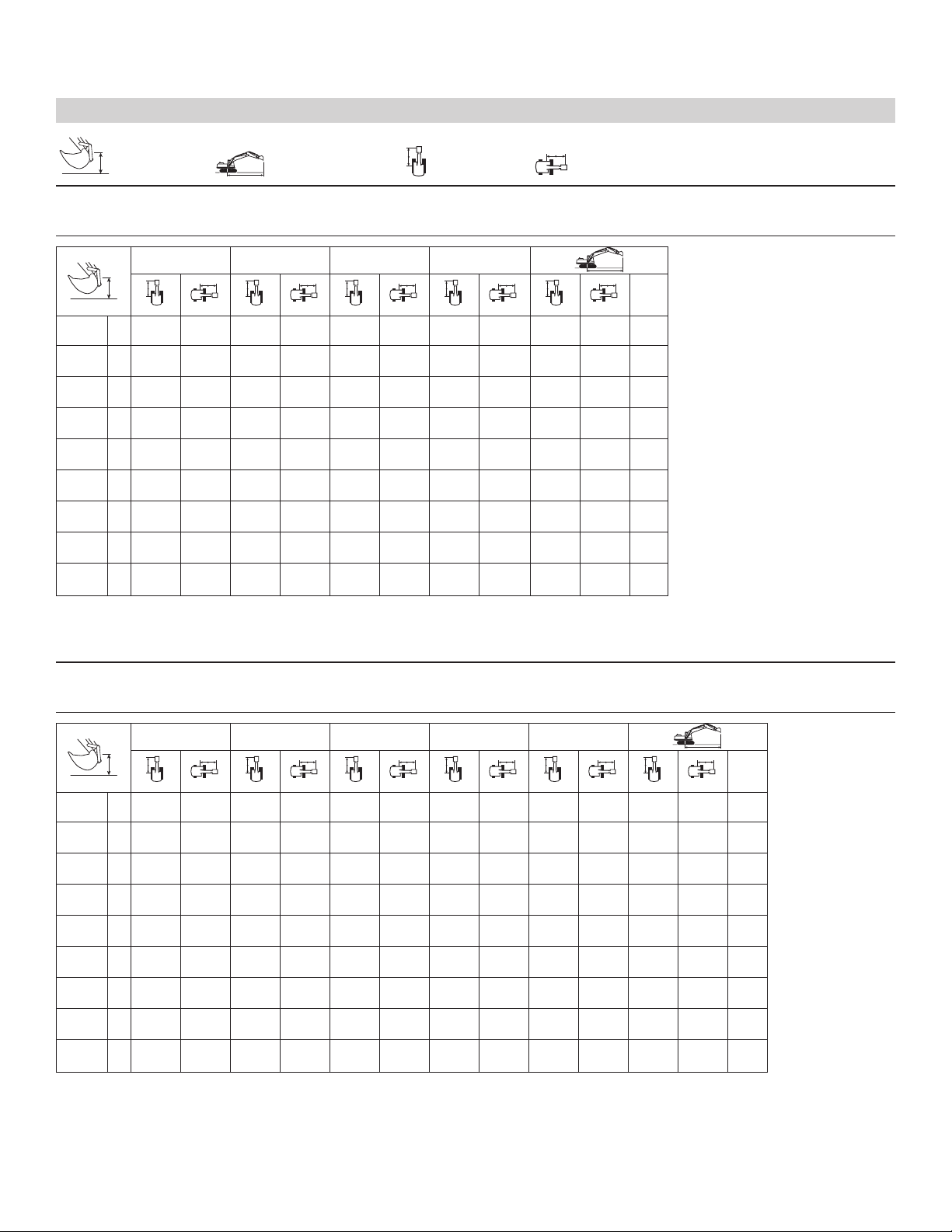
Load at
Maximum Reach
Load Point
Height
Load Radius
Over Front
Load Radius
Over Side
Reach Boom Lift Capacities
R2.7 STICK – 2.7 m (8'10")
BUCKET – 0.77 m3(1.0 yd3)
UNDERCARRIAGE – Long
SHOES – 700 mm (28") triple grouser
BOOM – Reach 5.3 m (17.4 ft)
COUNTERWEIGHT – 3.6 mt (7,940 lb)
* Indicates that the load is limited by hydraulic lifting capacity rather than tipping load. The above loads are in compliance with hydraulic excavator lift
capacity standard ISO 10567:2007. They do not exceed 87% of hydraulic lifting capacity or 75% of tipping load. Weight of all lifting accessories must be
deducted from the above lifting capacities. Lifting capacities are based on the machine standing on a firm, uniform supporting surface.
3.0 m (10.0 ft) 4.5 m (15.0 ft) 6.0 m (20.0 ft) 7.5 m (25.0 ft)
m
ft
7.5 m kg *1750 *1750 6.03
25.0 ft lb *3,700 *3,700 19.43
6.0 m kg *3700 *3700 *2300 *2300 7.09
20.0 ft lb *8,000 *8,000 *5,000 *5,000 23.09
4.5 m kg *4050 3700 *3000 2400 *2350 2250 7.71
15.0 ft lb *8,800 7,900 *5,150 5,000 25.20
3.0 m kg *6200 5650 *4800 3500 *4250 2350 *2450 2000 8.10
10.0 ft lb *13,300 12,100 *10,450 7,500 *8,850 4,950 *5,350 4,350 26.54
1.5 m kg *8100 5150 *5700 3300 4250 2250 *2600 1850 8.24
5.0 ft lb *17,400 11,100 *12,300 7,050 9,150 4,750 *5,700 4,100 27.04
Ground kg *9050 4900 6050 3150 4200 2150 *2900 1900 8.08
Line lb *19,500 10,550 12,950 6,700 8,950 4,600 *6,400 4,150 26.50
–1.5 m kg *7300 *7300 *9050 4850 5950 3050 *3500 2100 7.59
–5.0 ft lb *15,750 *15,750 *19,550 10,400 12,800 6,550 *7,700 4,600 24.87
–3.0 m kg *10550 9900 *8300 4900 6000 3100 *4600 2600 6.74
–10.0 ft lb *23,900 21,200 *17,900 10,550 *12,900 6,650 *10,200 5,700 21.98
–4.5 m kg *8650 *8650 *6250 5100 *5000 4000 5.27
–15.0 ft lb *18,400 *18,400 *13,200 11,000 *10,950 9,050 16.99
R3.2 STICK – 3.2 m (10'6")
BUCKET – 0.77 m3(1.0 yd3)
UNDERCARRIAGE – Long
SHOES – 700 mm (28") triple grouser
BOOM – Reach 5.3 m (17.4 ft)
COUNTERWEIGHT – 3.6 mt (7,940 lb)
* Indicates that the load is limited by hydraulic lifting capacity rather than tipping load. The above loads are in compliance with hydraulic excavator lift
capacity standard ISO 10567:2007. They do not exceed 87% of hydraulic lifting capacity or 75% of tipping load. Weight of all lifting accessories must be
deducted from the above lifting capacities. Lifting capacities are based on the machine standing on a firm, uniform supporting surface.
Always refer to the appropriate Operation and Maintenance Manual for specific product information.
1.5 m (5.0 ft) 3.0 m (10.0 ft) 4.5 m (15.0 ft) 6.0 m (20.0 ft) 7.5 m (25.0 ft)
m
ft
7.5 m kg *1750 *1750 6.84
25.0 ft lb *3,750 *3,750 22.11
6.0 m kg *3150 *3150 *1850 *1850 7.78
20.0 ft lb *6,950 *6,950 *4,050 *4,050 25.37
4.5 m kg *3600 *3600 *3250 2450 *1900 *1900 8.32
15.0 ft lb *7,800 *7,800 *6,850 5,200 *4,150 *4,150 27.24
3.0 m kg *5450 *5450 *4400 3550 *3900 2350 *2000 1750 8.63
10.0 ft lb *11,700 *11,700 *9,500 7,600 *8,500 5,000 *4,350 3,800 28.30
1.5 m kg *7500 5250 *5350 3300 4300 2250 *2100 1650 8.76
5.0 ft lb *16,100 11,300 *11,550 7,100 9,150 4,750 *4,600 3,600 28.73
Ground kg *8750 4950 6050 3150 4200 2150 *2300 1650 8.61
Line lb *18,900 10,600 13,000 6,700 8,950 4,550 *5,100 3,600 28.24
–1.5 m kg *7100 *7100 *9100 4800 5950 3050 4100 2100 *2700 1800 8.16
–5.0 ft lb *16,300 *16,300 *19,650 10,350 12,750 6,500 8,800 4,450 *6,000 3,950 26.73
–3.0 m kg *7800 *7800 *11 600 9750 *8600 4850 5950 3050 *3450 2200 7.35
–10.0 ft lb *16,950 *16,950 *26,100 20,850 *18,600 10,350 12,750 6,500 *7,700 4,800 24.05
–4.5 m kg *10 100 10 050 *7150 5000 *4700 3100 6.07
–15.0 ft lb *21,550 21,500 *15,200 10,700 *10,300 6,950 19.66
17
Page 18
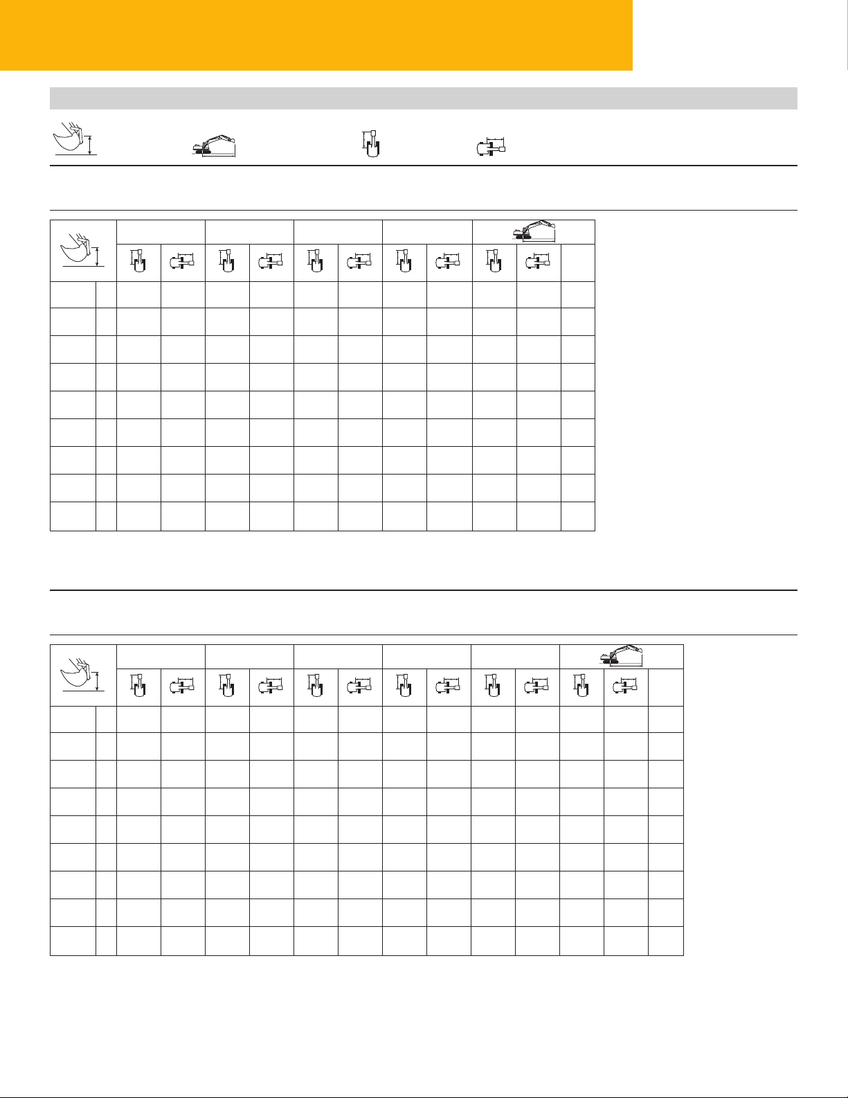
Load at
Maximum Reach
Load Point
Height
Load Radius
Over Front
Load Radius
Over Side
Reach Boom Lift Capacities
R2.7 STICK – 2.7 m (8'10")
BUCKET – 0.77 m3(1.0 yd3)
UNDERCARRIAGE – Long
SHOES – 790 mm (31") triple grouser
BOOM – Reach 5.3 m (17.4 ft)
COUNTERWEIGHT – 3.6 mt (7,940 lb)
* Indicates that the load is limited by hydraulic lifting capacity rather than tipping load. The above loads are in compliance with hydraulic excavator lift
capacity standard ISO 10567:2007. They do not exceed 87% of hydraulic lifting capacity or 75% of tipping load. Weight of all lifting accessories must be
deducted from the above lifting capacities. Lifting capacities are based on the machine standing on a firm, uniform supporting surface.
3.0 m (10.0 ft) 4.5 m (15.0 ft) 6.0 m (20.0 ft) 7.5 m (25.0 ft)
m
ft
7.5 m kg *1750 *1750 6.03
25.0 ft lb *3,700 *3,700 19.43
6.0 m kg *3700 *3700 *2350 *2300 7.09
20.0 ft lb *8,000 *8,000 *5,000 *5,000 23.09
4.5 m kg *4050 3750 *3000 2450 *2350 2300 7.71
15.0 ft lb *8,800 8,000 *5,150 5,100 25.20
3.0 m kg 6200 5700 *4800 3550 *4250 2350 *2450 2050 8.10
10.0 ft lb 13,300 12,250 *10,450 7,600 *8,850 5,050 *5,350 4,450 26.54
1.5 m kg 8100 5250 *5700 3350 4350 2250 *2600 1900 8.24
5.0 ft lb 17,400 11,250 *12,300 7,150 9,300 4,850 *5,700 4,150 27.04
Ground kg 9050 5000 6150 3200 4250 2200 *2900 1900 8.08
Line lb 19.500 10,700 13,150 6,800 9,100 4,650 *6,400 4,200 26.5
–1.5 m kg *7300 *7300 *9050 4950 6050 3100 *3500 2100 7.59
–5.0 ft lb *15,750 *15,750 *19,550 10,550 13,000 6,650 *7,700 4,650 24.87
–3.0 m kg *10 550 10 050 *8300 5000 *6000 3150 *4600 2650 6.74
–10.0 ft lb *23,900 21,500 *17,900 10,700 *12,900 6,750 *10,200 5,800 21.98
–4.5 m kg *8650 *8650 *6250 5200 *5000 4050 5.27
–15.0 ft lb *18,400 *18,400 *13,200 11,150 *10,950 9,200 16.99
R3.2 STICK – 3.2 m (10'6")
BUCKET – 0.77 m3(1.0 yd3)
UNDERCARRIAGE – Long
SHOES – 790 mm (31") triple grouser
BOOM – Reach 5.3 m (17.4 ft)
COUNTERWEIGHT – 3.6 mt (7,940 lb)
* Indicates that the load is limited by hydraulic lifting capacity rather than tipping load. The above loads are in compliance with hydraulic excavator lift
capacity standard ISO 10567:2007. They do not exceed 87% of hydraulic lifting capacity or 75% of tipping load. Weight of all lifting accessories must be
deducted from the above lifting capacities. Lifting capacities are based on the machine standing on a firm, uniform supporting surface.
Always refer to the appropriate Operation and Maintenance Manual for specific product information.
1.5 m (5.0 ft) 3.0 m (10.0 ft) 4.5 m (15.0 ft) 6.0 m (20.0 ft) 7.5 m (25.0 ft)
m
ft
7.5 m kg *1750 *1750 6.84
25.0 ft lb *3,750 *3,750 22.11
6.0 m kg *3150 *3150 *1850 *1850 7.78
20.0 ft lb *6,950 *6,950 *4,050 *4,050 25.37
4.5 m kg *3600 *3600 *3250 2500 *1900 *1900 8.32
15.0 ft lb *7,800 *7,800 *6,850 5,250 *4,150 *4,150 27.24
3.0 m kg *5450 *5450 *4400 3600 *3900 2400 *2000 1750 8.63
10.0 ft lb *11,700 *11,700 *9,500 7,700 *8,500 5,100 *4,350 3,900 28.30
1.5 m kg *7500 5350 *5350 3350 4350 2250 *2100 1650 8.76
5.0 ft lb *16,100 11,450 *11,550 7,200 9,300 4,850 *4,600 3,650 28.73
Ground kg *8750 5000 *6100 3200 4250 2150 *2300 1700 8.61
Line
lb *18,900 10,750 13,150 6,800 9,100 4,650 *5,100 3,700 28.24
–1.5 m kg *7100 *7100 *9100 4900 6050 3100 4200 2100 *2700 1850 8.16
–5.0 ft lb *16,300 *16,300 *19,650 10,500 12,950 6,600 8,950 4,500 *6,000 4,050 26.73
–3.0 m kg *7800 *7800 *11 600 9900 *8600 4900 6050 3100 *3450 2200 7.36
–10.0 ft lb *16,950 *16,950 *26,100 21,150 *18,600 10,550 12,950 6,600 *7,700 4,900 24.05
–4.5 m kg *10 100 *10 100 *7150 5050 *4700 3150 6.07
–15.0 ft lb *21,550 *21,550 *15,200 10,850 *10,300 7,100 19.66
319D L/319D LN Hydraulic Excavator Specifications
18
Page 19
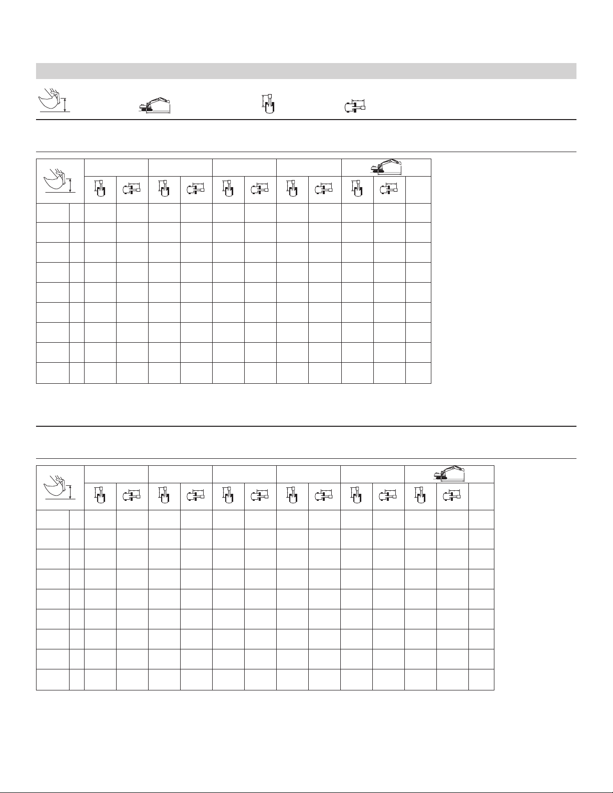
Load at
Maximum Reach
Load Point
Height
Load Radius
Over Front
Load Radius
Over Side
Reach Boom Lift Capacities
R2.7 STICK – 2.7 m (8'10")
BUCKET – 0.77 m3(1.0 yd3)
UNDERCARRIAGE – Long Narrow
SHOES – 600 mm (24") triple grouser
BOOM – Reach 5.3 m (17.4 ft)
COUNTERWEIGHT – 3.9 mt (8,600 lb)
* Indicates that the load is limited by hydraulic lifting capacity rather than tipping load. The above loads are in compliance with hydraulic excavator lift
capacity standard ISO 10567:2007. They do not exceed 87% of hydraulic lifting capacity or 75% of tipping load. Weight of all lifting accessories must be
deducted from the above lifting capacities. Lifting capacities are based on the machine standing on a firm, uniform supporting surface.
3.0 m (10.0 ft) 4.5 m (15.0 ft) 6.0 m (20.0 ft) 7.5 m (25.0 ft)
m
ft
7.5 m kg *1750 *1750 6.03
25.0 ft lb *3,700 *3,700 19.43
6.0 m kg *3700 3500 *2300 *2300 7.09
20.0 ft lb *8,000 7,450 *5,000 *5,000 23.09
4.5 m kg *4050 3400 *3000 2200 *2350 2050 7.71
15.0 ft lb *8,800 7,250 *5,150 4,550 25.20
3.0 m kg *6200 5150 *4800 3200 *4250 2100 *2450 1800 8.10
10.0 ft lb *13,300 11,050 *10,450 6,850 *8,850 4,500 *5,350 3,950 26.54
1.5 m kg *8100 4650 *5700 3000 4350 2000 *2600 1700 8.24
5.0 ft lb *17,400 10,050 *12,300 6,400 9,250 4,300 *5,700 3,650 27.04
Ground kg *9050 4450 6150 2850 4250 1950 *2900 1700 8.08
Line lb *19,500 9,500 13,150 6,050 9,100 4,150 *6,400 3,700 26.50
–1.5 m kg *7300 *7300 *9050 4400 6050 3750 *3500 1900 7.59
–5.0 ft lb *15,750 *15,750 *19,550 9,400 12,950 5,900 *7,700 4,150 24.87
–3.0 m kg *10 550 8800 *8300 4450 *6000 2800 *4600 2350 6.74
–10.0 ft lb *23,900 18,850 *17,900 9,500 *12,900 6,000 *10,200 5,200 21.98
–4.5 m kg *8650 *8650 *6250 4650 *5000 3600 5.27
–15.0 ft lb *18,400 *18,400 *13,200 9,950 *10,950 8,200 16.99
R3.2 STICK – 3.2 m (10'6")
BUCKET – 0.77 m3(1.0 yd3)
UNDERCARRIAGE – Long Narrow
SHOES – 600 mm (24") triple grouser
BOOM – Reach 5.3 m (17.4 ft)
COUNTERWEIGHT – 3.9 mt (8,600 lb)
* Indicates that the load is limited by hydraulic lifting capacity rather than tipping load. The above loads are in compliance with hydraulic excavator lift
capacity standard ISO 10567:2007. They do not exceed 87% of hydraulic lifting capacity or 75% of tipping load. Weight of all lifting accessories must be
deducted from the above lifting capacities. Lifting capacities are based on the machine standing on a firm, uniform supporting surface.
Always refer to the appropriate Operation and Maintenance Manual for specific product information.
1.5 m (5.0 ft) 3.0 m (10.0 ft) 4.5 m (15.0 ft) 6.0 m (20.0 ft) 7.5 m (25.0 ft)
m
ft
7.5 m kg *1750 *1750 6.84
25.0 ft lb *3,750 *3,750 22.11
6.0 m kg *3150 *3150 *1850 *1850 7.78
20.0 ft lb *6,950 *6,950 *4,050 *4,050 25.37
4.5 m kg *3600 3450 *3250 2250 *1900 1750 8.32
15.0 ft lb *7,800 7,350 *6,850 4,700 *4,150 3,850 27.24
3.0 m kg *5450 5250 *4400 3250 *3900 2150 *2000 1550 8.63
10.0 ft lb *11,700 11,350 *9,500 6,950 *8,500 4,550 *4,350 3,450 28.30
1.5 m kg *7500 4750 *5350 3000 4350 2000 *2100 1450 8.76
5.0 ft lb *16,100 10,250 *11,550 6,450 9,300 4,300 *4,600 3,200 28.73
Ground kg *8750 4450 *6100 2850 4250 1950 *2300 1500 8.61
Line lb *18,900 9,550 13,150 6,050 9,050 4,100 *5,100 3,250 28.24
–1.5 m kg *7100 *7100 *9100 4350 6000 2750 4200 1900 *2700 1600 8.16
–5.0 ft lb *16,300 *16,300 *19,650 9,300 12,900 5,850 8,950 4,000 *6,000 3,550 26.73
–3.0 m kg *7800 *7800 *11 600 8650 *8600 4350 6000 2750 *3450 1950 7.36
–10.0 ft lb *16,950 *16,950 *26,100 18,500 *18,600 9,350 12,900 5,850 *7,700 4,350 24.05
–4.5 m kg *10 100 8900 *7150 4500 *4700 2800 6.07
–15.0 ft lb *21,550 19,100 *15,200 9,650 *10,300 6,300 19.66
19
Page 20
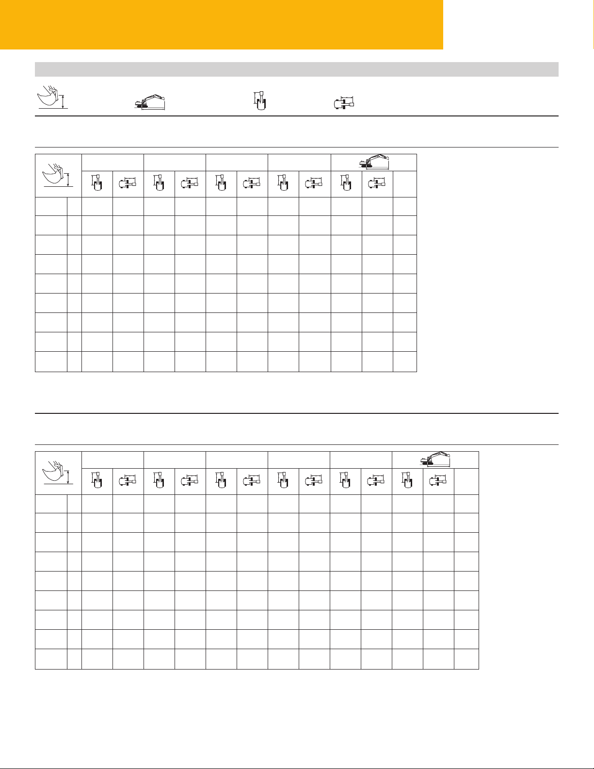
R3.2 STICK – 3.2 m (10'6")
BUCKET – 0.77 m3(1.0 yd3)
UNDERCARRIAGE – Long Narrow
SHOES – 600 mm (24") triple grouser
BOOM – Reach 5.3 m (17.4 ft)
COUNTERWEIGHT – 3.6 mt (7,940 lb)
* Indicates that the load is limited by hydraulic lifting capacity rather than tipping load. The above loads are in compliance with hydraulic excavator lift
capacity standard ISO 10567:2007. They do not exceed 87% of hydraulic lifting capacity or 75% of tipping load. Weight of all lifting accessories must be
deducted from the above lifting capacities. Lifting capacities are based on the machine standing on a firm, uniform supporting surface.
1.5 m (5.0 ft) 3.0 m (10.0 ft) 4.5 m (15.0 ft) 6.0 m (20.0 ft) 7.5 m (25.0 ft)
m
ft
7.5 m kg *1750 *1750 6.84
25.0 ft lb *3,750 *3,750 22.11
6.0 m kg *3150 *3150 *1850 *1850 7.78
20.0 ft lb *6,950 *6,950 *4,050 *4,050 25.37
4.5 m kg *3600 3300 *3250 2100 *1900 1650 8.32
15.0 ft lb *7,800 7,050 *6,850 4,450 *4,150 3,650 27.24
3.0 m kg *5450 5050 *4400 3100 *3900 2000 *2000 1450 8.63
10.0 ft lb *11,700 10,850 *9,500 6,600 *8,500 4,300 *4,350 3,200 28.30
1.5 m kg *7500 4550 *5350 2850 4200 1900 *2100 1350 8.76
5.0 ft lb *16,100 9,800 *11,550 6,150 8,950 4,050 *4,600 3,000 28.73
Ground kg *8750 4250 5900 2700 4050 1800 *2300 1400 8.61
Line lb *18,900 9,100 12,700 5,750 8,700 3,850 *5,100 3,000 28.25
–1.5 m kg *7100 *7100 *9100 4150 5800 2600 4000 1750 *2700 1500 8.16
–5.0 ft lb *16,300 *16,300 *19,650 8,850 12,450 5,550 8,600 3,750 *6,000 3,300 26.73
–3.0 m kg *7800 *7800 *11 600 8250 *8600 4150 5800 2600 *3450 1850 7.36
–10.0 ft lb *16,950 *16,950 *26,100 17,700 *18,600 8,900 12,450 5,550 *7,700 4,100 24.05
–4.5 m kg *10 100 8550 *7150 4300 *4700 2650 6.07
–15.0 ft lb *21,550 18,300 *15,200 9,200 *10,300 6,000 19.66
R2.7 STICK – 2.7 m (8'10")
BUCKET – 0.77 m3(1.0 yd3)
UNDERCARRIAGE – Long Narrow
SHOES – 600 mm (24") triple grouser
BOOM – Reach 5.3 m (17.4 ft)
COUNTERWEIGHT – 3.6 mt (7,940 lb)
* Indicates that the load is limited by hydraulic lifting capacity rather than tipping load. The above loads are in compliance with hydraulic excavator lift
capacity standard ISO 10567:2007. They do not exceed 87% of hydraulic lifting capacity or 75% of tipping load. Weight of all lifting accessories must be
deducted from the above lifting capacities. Lifting capacities are based on the machine standing on a firm, uniform supporting surface.
Always refer to the appropriate Operation and Maintenance Manual for specific product information.
3.0 m (10.0 ft) 4.5 m (15.0 ft) 6.0 m (20.0 ft) 7.5 m (25.0 ft)
m
ft
7.5 m kg *1750 *1750 6.03
25.0 ft lb *3,700 *3,700 19.43
6.0 m kg *3700 *3350 *2300 *2300 7.09
20.0 ft lb *8,000 *7,150 *5,000 *5,000 23.09
4.5 m kg *4050 3250 *3000 2100 *2350 1950 7.71
15.0 ft lb *8,800 6,900 *5,150 4,300 25.20
3.0 m kg *6200 4900 *4800 3050 *4250 2000 *2450 1700 8.10
10.0 ft lb *13,300 10,600 *10,450 6,500 *8,850 4,250 *5,350 3,700 26.54
1.5 m kg *8100 4450 *5700 2850 4150 1900 *2600 1600 8.24
5.0 ft lb *17,400 9,600 *12,300 6,050 8,950 4,050 *5,700 3,450 27.04
Ground kg *9050 4200 5900 2700 4100 1850 *2900 1600 8.08
Line lb *19,500 9,050 12,650 5,750 8,750 3,900 *6,400 3,500 26.50
–1.5 m kg *7300 *7300 *9050 4150 5850 2600 *3500 1750 7.59
–5.0 ft lb *15,750 *15,750 *19,550 8,950 12,500 5,600 *7,700 3,900 24.87
–3.0 m kg *10 550 8400 *8300 4200 5850 2650 *4600 2200 6.74
–10.0 ft lb *23,900 18,000 *17,900 9,050 12,600 5,650 *10,200 4,900 21.98
–4.5 m kg *8650 *8650 *6250 4400 *5000 3450 5.27
–15.0 ft lb *18,400 18,400 *13,200 9,500 *10,950 7,800 16.99
Load at
Maximum Reach
Load Point
Height
Load Radius
Over Front
Load Radius
Over Side
Reach Boom Lift Capacities
319D L/319D LN Hydraulic Excavator Specifications
20
Page 21

319D L/319D LN Standard Equipment
Standard equipment may vary. Consult your Caterpillar dealer for details
Alternator, 50 amp
Automatic engine speed control
Automatic swing brake
Bolt-on Falling Object Guard System
(FOGS) capability
Cab
• AM/FM radio, 24-volt
• Ashtray with cigar lighter
• Coat hook
• Drink holder
• Economy mode
• Horn
Counterweight 3.6 mt (7,940 lb)
Language display monitor (full graphic/full
color display)
• Clock
• Filter/uid change information
• Level check for hydraulic oil, engine oil
and coolant
• Warning messages
Light, interior
Literature holder
Openable front windshield
Openable skylight with sunshade
Positive ltered ventilation
Storage compartment
Travel control pedals with removable
hand levers
Door locks and caps lock with one-key
security system
Light, storage box mounted (1)
319D L/319D LN Optional Equipment
Mirrors (frame and cab)
Power train
• Cat® C4.2 engine with ACERT™
Technology
• 24-volt electric starter
• Air intake heater
• Water separator
Radial seal air lter, double element
Reverse swing damping valve
Undercarriage
• Greased track adjusters
• Idler and center section track guiding
guards
• Track-type undercarriage with grease
lubricated seals
Optional equipment may vary. Consult your Caterpillar dealer for details
Air prelter
Auxiliary hydraulics
Auxiliary hydraulic lines for booms and
sticks
Boom lowering and overload warning
control device
Bucket linkage
Cab mounted working lights
Cab mounted working lights with time
delay function
Cold weather start
Counterweight 3.9 mt (8,600 lb)
Fine swing control
Falling Object Guarding System (FOGS)
Front windshield guard
Hand control pattern changer
Heavy-duty bottom guard
High ambient cooling system
Power supply 12V-7A
Pull down sunscreen
Rain protector
Rear view camera
Right-side boom lights
Secondary exit, rear window
Steel bumper
Stick and boom combinations
• 3.2 m (10 ft 6 in) stick
• 2.7 m (8 ft 10 in) stick
• 2.25 m (7 ft 5 in) stick
Straight travel pedal
Sun visor
Swivel guard
Vandalism protection
Water level indicator with water separator
21
Page 22

Notes
22
Page 23

Notes
23
Page 24

319D L/319D LN Hydraulic Excavator
For more complete information on Cat products, dealer services, and industry solutions, visit
us on the web at www.cat.com
© 2008 Caterpillar Inc.
All rights reserved
Materials and specifications are subject to change without notice. Featured machines in may
include additional equipment. See your Caterpillar dealer for available options.
CAT, CATERPILLAR, ACERT, SAFETY.CAT.COM, their respective logos, “Caterpillar Yellow” and
the POWER EDGE trade dress, as well as corporate and product identity used herein, are
trademarks of Caterpillar and may not be used without permission.
12
AEHQ6010 (10-2008)
 Loading...