

Page 1
版次 : 2017年10月
Wall Mount Bracket YM-81
Wall Mount Bracket YM-81
CN/JA/EN/DE/FR/ES/IT/SV/RU/PT/TR/NL/PL/FI/CS/NO/LT/TH/ID/MS/VI/TW/KO/AR
取扱説明書
日本語
User’s Guide
English
Bedienungsanleitung
Deutsch
Mode d’emploi
Français
Español Italiano Svenska Português
Nederlands Suomi
Norsk
http://world.casio.com/manual/projector/
Page 2
This product provides wall mount bracket for CASIO Data Projectors.
CASIO COMPUTER CO., LTD. shall not be held liable for any loss or lost profits due to any accidents
or damages due to improper installation, defective assembly, or improper handling of this product.
The illustrations shown in this manual are for demonstration purposes only and their contents may
be different from the actual appearance of the product.
The contents of this manual are subject to change without notice.
Wall Mount Bracket
YM-81
User’s Guide
Be sure to keep all user documentation handy for future reference.
To obtain the latest version of this manual, visit the website at the URL below.
http://world.casio.com/manual/projector/
Contents
Safety Precautions .................................. EN-2
Operating Precautions ............................ EN-3
Unpacking ................................................ EN-5
Installing the Wall Mount Bracket.......... EN-7
Adjusting the Position, Elevation,
and Angle ............................................... EN-18
Attaching the Covers .............................EN-25
Periodic Inspection ................................EN-27
Contact.................................................... EN-27
Product Specifications ..........................EN-27
EN-1
Page 3
Safety Precautions
Thank you for selecting this CASIO product. Be sure to read these “Safety Precautions” before trying to
use it. After reading this User’s Guide, keep it in a safe place for future reference.
About safety symbols
Various symbols are used in this User’s Guide and on the product itself to ensure safe use, and to
protect you and others against the risk of injury and against material damage. The meaning of each of the
symbols is explained below.
Icon Examples
*
Danger
This symbol indicates information that, if ignored or applied incorrectly,
creates the risk of death or serious personal injury.
*
Warning
This symbol indicates information that, if ignored or applied incorrectly, could
possibly create the risk of death or serious personal injury.
*
Caution
This symbol indicates information that, if ignored or applied incorrectly, could
possibly create the risk of personal injury or material damage.
’
A triangle indicates a situation against which you need to exercise caution. The example shown
here indicates you should take precaution against electric shock.
!
A circle with a line through it indicates information about an action that you should not perform.
The specific action is indicated by the figure inside the circle. The example shown here means
disassembly is prohibited.
$
A black circle indicates information about an action that you must perform. The specific action
is indicated by the figure inside the circle. The example shown here indicates you must unplug
the power cord from the power outlet.
*
Warning
This Projector System is sold under the
assumption that installation will be
performed by specialists who possess an
adequate level of technological
experiences and knowledge. This product
must be installed by trained specialists.
Installation by non-specialists creates the
risk of the bracket and projector falling
down and other problems.
Improper assembly creates the risk of the
bracket and projector falling down and
other problems. Make sure that you
always observe the precautions below.
• Be sure to check that the installation provides
sufficient strength and make sure everything is
assembled correctly.
• Be sure to tighten all screws fully and securely.
EN-2
This product and the projector it supports
weigh approximately 13 kilograms (28.7
lbs). During installation, be sure to take the
actions described below.
• Calculate the allowable load of all anchors and
bolts being used for installation.
• Avoid subjecting the projector to undue force
when installing it.
Make sure that the projector is grounded
during use.
Page 4

Operating Precautions
*
Warning
This product does not have rotary angle
adjustment. After adjusting the elevation
and angle, never rotate the projector
while the screws are tightened. After
installation is complete, leave all
elevation and angle adjustments up to
qualified specialists. Adjustment by
non-specialists creates the risk of the
bracket and projector falling down.
After the Projector System is installed, never
loosen any of its bolts, screws, or nuts.
Adjustment by non-specialists creates the risk
of the bracket and projector falling down.
Should you ever notice any part or component
has fallen from the bracket/projector,
immediately check the installation.
Never allow anything to be hung from the
bracket. Doing so creates the risk of the bracket
and projector falling down and other problems.
After installation is complete, leave all
maintenance work up to qualified specialists.
For information about projector maintenance,
see the projector user’s guide.
Do not place heavy objects on the projector or
wall mount bracket, and do not allow anyone to
climb onto them.
Make sure that the installation does not result in
blocking of the projector’s intake and exhaust
vents. Periodically check the projector to ensure
that its intake and exhaust vents are note
clogged by dust build-up. Should dust build up,
clean the vents before using the projector.
When installing up and adjusting the wall mount
bracket, take care to avoid pinching your hands
between metal parts.
Never use any type of screws except for those
that are specified. Use of non-specified screws
creates the risk of the projector falling down and
other problems.
Never try to modify the wall mount bracket in
any way. (The strength of modified bracket
cannot be guaranteed.)
Installation Location
Precautions
Never install this product in any of the types of
locations below.
• Areas subject to high or low temperatures
•Outdoors
• Areas subject to strong vibration
• Food preparation areas and other locations
where there is the chance of contact with oil
smoke, and areas where there are large
amounts of tobacco smoke present.
• Areas subject to high moisture
• Bathrooms and other areas where the
projector may become wet
• On an unstable and/or slanted surface
• In the vicinity of the entrance to a retail
location (Where there is the risk of exposure
to rain.)
When installing a projector, keep it away from
fluorescent lighting, air conditioning, and other
electrical devices. Some fluorescent lighting can
interfere with operation of the projector’s remote
control system.
Make sure that the projector’s power key is
located in a position where it can be used to turn
off the projector in order recover from projector
operation errors, to protect internal circuitry, and
to save energy.
In order to ensure noise-free projection images,
use of a cable no more than 10 meters long is
recommended when connecting a computer or
other device. Also, keep the connecting cable
away from the AC cord.
In order to avoid soiling of the lens and internal
light source, install the projector in a location
where there is little chance of exposure to dust
and moisture.
When direct sunlight is shining into the room,
the projection image can be made easier to see
by drawing curtains over windows.
Light and heat emitted by the projector may
cause discoloration of its surroundings.
Avoid mounting at a height that allows the
projector to be touched by people. If a relatively
low installation position is unavoidable, take
care to install in a way that avoids head and
other injury.
Make sure that the projection side of the
projector is at least 6 cm (2.4 inches) from the
projection surface (wall), and all other sides are
at least 30 cm (11.8 inches) from surrounding
surfaces. There should be no other objects
within the above distances from the projector.
EN-3
Page 5

Operating Precautions
Concrete
When mounting on a concrete wall, use
appropriate components (M10 nuts,
bolts, etc.) to support the weight of the
projector and bracket, and to prevent
lateral sway. Adjustment by
non-specialists creates the risk of the
bracket and projector falling down.
CASIO COMPUTER CO., LTD. shall be held in
no way liable for any losses due to the bracket
and/or projector falling down due to the use of
installation components of insufficient strength.
Plaster and Similar Material
When anchoring the bracket on a wall made of
plaster or other low-strength material, drive
anchor bolts into the concrete under the wall.
Install using anchor bolts in at least eight
locations.
Recommendations for Wall
Installation
In order to ensure a high level of safety for wall
installation, the CASIO Data Projector wall mount
bracket comes with wire to prevent dropping.
When installing the projector, be sure to have the
wire attached to the projector and bracket.
EN-4
Page 6
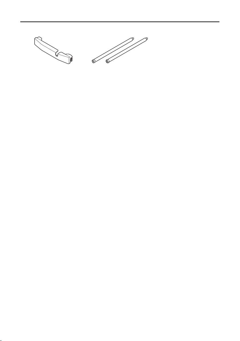
Unpacking
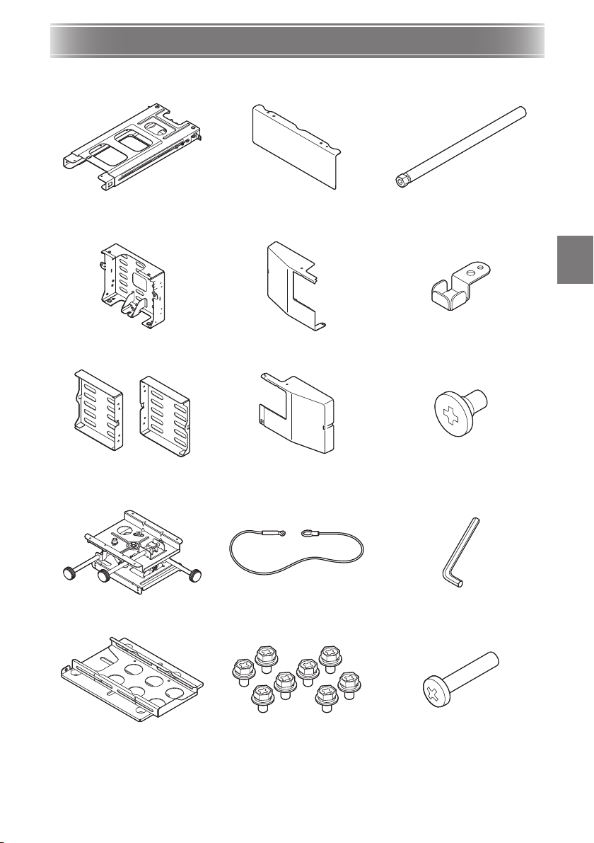
As you unpack the product, check to make sure that all of the items listed below are present.
Values in brackets (< >) indicate quantities.
Arm unit <1> Middle wall anchor plate cover
Middle wall anchor plate <1> Left wall anchor plate cover <1> Arm screw covers <2>
Left and right wall anchor plates
<2>
Adjuster unit <1> Safety wire <1> Hex wrench <1>
Right wall anchor plate cover <1> M5×8mm shoulder screws <3>
<1>
M10×152mm arm vertical
adjustment screw <1>
Bracket (with projector anchor
plate) <1>
M4×8mm hex head screws <22> M4×20mm screw <1>
EN-5
Page 7
Unpacking
Arm cover <1> M10×194mm arm screws <2>
Items that need to be prepared by you
Anchor bolts (M10 – at least 8)
Screwdriver
Positioning sheet <1>
User’s Guide (This Manual)
<1>
EN-6
Page 8
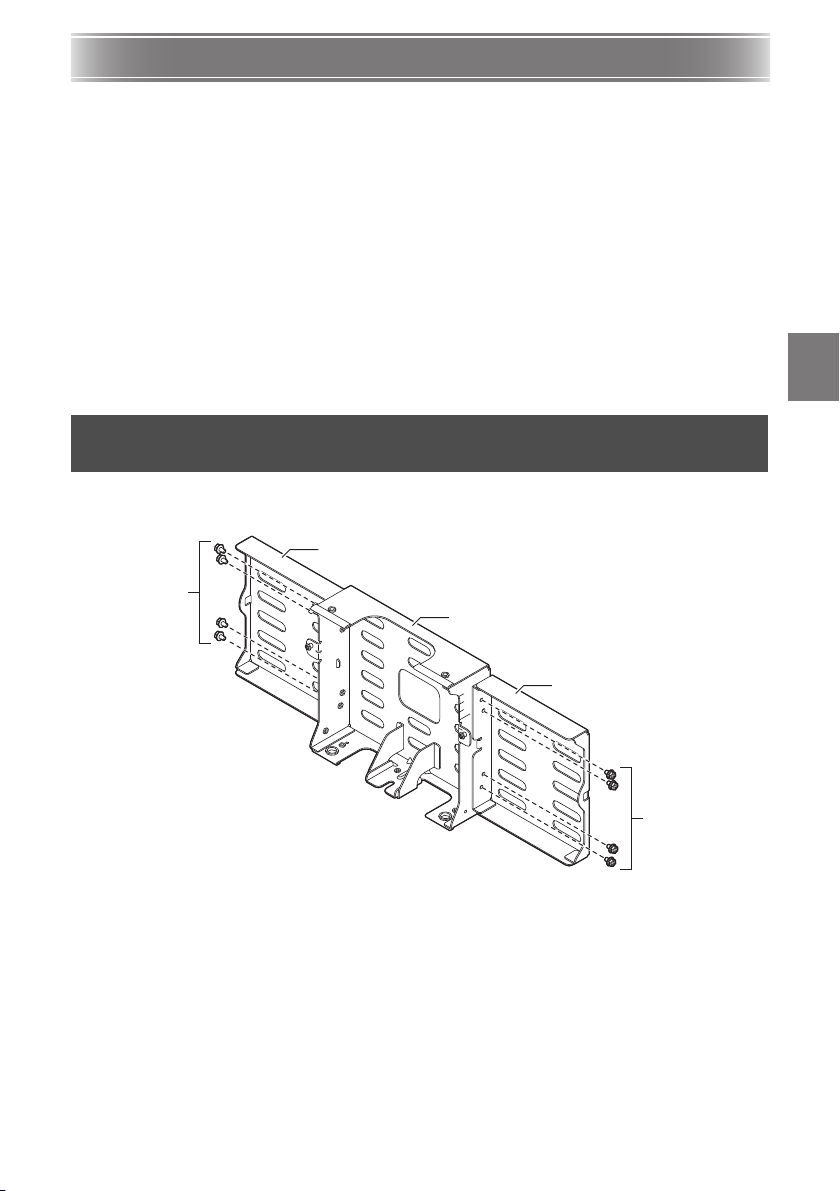
Installing the Wall Mount Bracket
Left wall anchor plate
M4×8mm hex head
screws
Middle wall anchor plate
Right wall anchor plate
M4×8mm hex head
screws
Precautions During Installation
Be sure to follow the procedures in this manual to ensure that installation work is performed correctly.
Make sure that screws, metal parts, and all other components are all installed securely.
Check to make sure that the wall where the bracket is to be installed can support the weight of the
bracket, and arrange for installation plans and installation work.
Before starting installation work, make sure that the projector is turned off and that is power cord is
unplugged.
Take care to avoid dropping the projector.
Take care when handling small components. Small components can be swallowed by children or pets.
Should this happen, contact a physician immediately.
Improperly tightened screws can cause the case to crack and the projector to fall, creating the risk of
accident and personal injury. Do not use any thread locking adhesive, lubricant, oil, or other similar
agents on the screws that anchor the projector to the wall.
After installation and adjustment are complete, check all screws to ensure that they are properly
tightened. Take care that screws are not loose and also avoid over-tightening them.
After installation is complete, store this manual and other items that come with the bracket in a safe
place.
1. Assemble the wall anchor plates and attach them to the
wall.
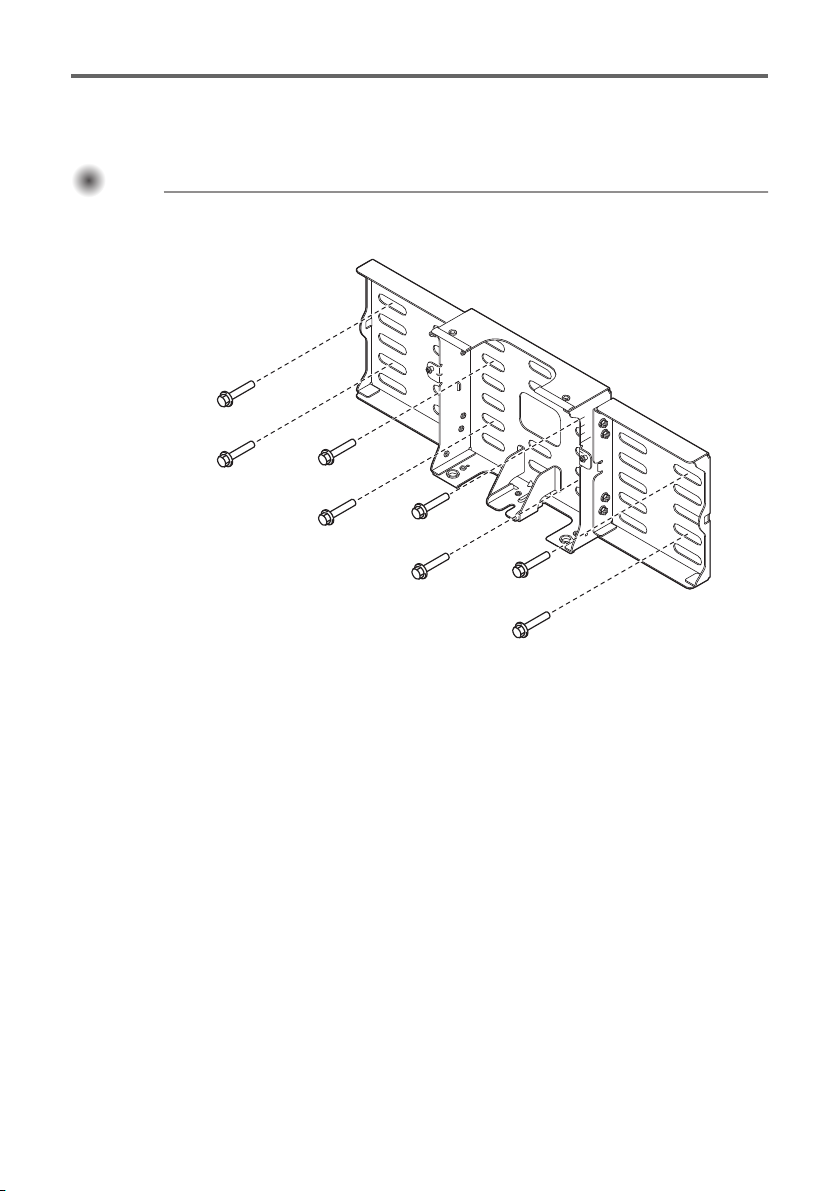
1. Affix the left and right wall anchor plates to the middle wall anchor plate using eight
M4×8mm hex head screws.
2. Referring to “Screen Size and Wall Anchor Plate Mounting Dimension Diagram”
3. Referring to “Positioning the Installation Holes of the Wall Anchor Plates” (page
(page EN-9), determine the installation position.
EN-10), drill holes in the wall.
EN-7
Page 9
Installing the Wall Mount Bracket
Important!Important!Important!
Anchor bolts (at least 8)
4. Use the anchor bolts to attach the anchor plates to the wall.
Securely attach the anchor plates to the wall using at least eight anchor bolts: at least four for the
middle wall anchor plate, and at least two each for the left and right wall anchor plate.
With a projector installed, this product weighs approximately 13 kilograms (28.7 lbs). When
attaching this product to a wall, carefully consider pull out strength and installation strength. If
greater strength is required, increase the number of anchor bolts used for attachment.
EN-8
Page 10

Installing the Wall Mount Bracket
413
62.7
205
502.8
200
141
126.1
333 L
205
69
MAX.722.1 - MIN.501.1
161.2
43.8
(233)
76.4
H
Unit : mm
Screen Size
Center of projection screen
Center of wall anchor plate
Screen Thickness
Ceiling
Screen Size and Wall Anchor Plate Mounting Dimension Diagram
Screen
WXGA XGA
Size (inch)L(mm/inch)H(mm/inch)L(mm/inch)H(mm/inch)
50 - / - - / - 121 / 4.8 253 / 10.0
60 128 / 5.0 240 / 9.4 202 / 8.0 288 / 11.3
70 197 / 7.8 267 / 10.5 285 / 11.2 323 / 12.7
80 267 / 10.5 294 / 11.6 366 / 14.4 358 / 14.1
90 336 / 13.2 322 / 12.7 444 / 17.5 393 / 15.5
100 404 / 15.9 348 / 13.7 - / - - / -
110 469 / 18.5 374 / 14.7 - / - - / -
Distance values above are only for reference during installation.
EN-9
Page 11

2.
1.
3.
1.
Installing the Wall Mount Bracket
Positioning the Installation Holes of the Wall Anchor Plates
1. Align the marks on the upper edges of the projection screen printed on the
positioning sheet with the upper edges of the projection screen.
The scales on either side of the positioning sheet indicate millimeter units.
2. Align the positioning sheet with the center of the projection screen.
Position the center of the wall anchor plate 62.7 mm (2.5 inches) to the right of the center of the
projection screen.
3. Drill holes in the wall in accordance with the image on the positioning sheet.
B
EN-10
Page 12

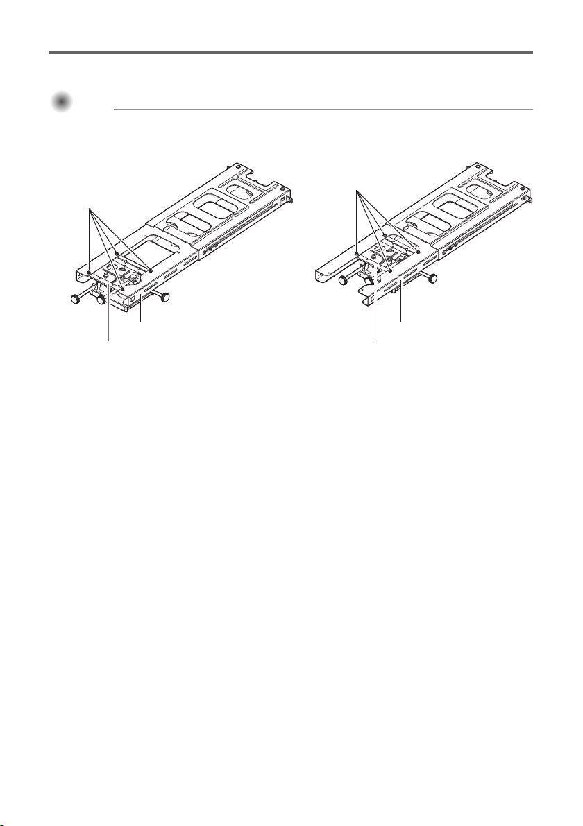
Installing the Wall Mount Bracket
Adjuster unit
Bracket (with projector anchor plate)
Hex head screw
Inner arm
Outer arm
Arm unit
Adjuster unit
2. Install the adjuster unit onto the arm unit.
1. Remove the bracket from the adjuster unit.
The adjuster unit is packed with the bracket attached. Remove the bracket as shown in the
illustration.
2. Loosen the arm unit hex head screw indicated in the illustration and then pull out
the inner arm. Next, orient the adjuster unit as shown in the illustration and insert it
into the inner arm.
EN-11
Page 13
Installing the Wall Mount Bracket
Important!Important!Important!
M4×8mm hex head screws
M4×8mm hex head screws
Inner arm
Adjuster unit
WXGA: 80-inch or larger projection size
XGA: 70-inch or larger projection size
WXGA: 70-inch or smaller projection size
XGA: 60-inch or smaller projection size
Inner arm
Adjuster unit
3. Secure the adjuster unit to the inner arm using four M4×8mm hex head screws.
As shown in the illustrations below, you need to determine the adjuster unit installation location
on the inner arm in accordance with your projector’s resolution (WXGA or XGA) and the desired
projection size.
EN-12
Page 14

Installing the Wall Mount Bracket
Important!Important!Important!
Arm unit
Arm vertical adjustment screw
Red mark
Groove
Middle wall anchor plate
Temporary mounting screws
Arm unit
Slide the groove of the hex head end of the arm
vertical adjustment screw into the U-slot of the
middle wall anchor plate.
U-slot
Inner arm
Hex head screw
3. Install the arm unit on the wall anchor plates.
1. Insert the M10×152mm arm vertical adjustment screw into the hole of the arm unit.
Align the red mark of the adjustment screw as shown in the illustration.
2. Temporarily hook the arm unit onto the two screws of the middle wall anchor plate.
You do not need to tighten the screws.
Note that if the hex head screw of the arm unit is loose, the inner arm will tend to move too
easily.
EN-13
Page 15

Installing the Wall Mount Bracket
M4×8mm hex head screws
Arm screws
Arm screw covers
Temporary mounting screws
3. Insert the two M10×194mm arm screws into the holes in the middle wall anchor
plate, and then tighten the screws with the provided hex wrench.
4. Secure the two arm screw covers with the M4×8mm hex head screws.
5. Remove the temporary mounting screws that you hooked the arm onto in step 2 of
this procedure, and then install them in the appropriate locations on the sides of the
middle wall anchor plate.
EN-14
Page 16

Installing the Wall Mount Bracket
Important!Important!Important!
M4×8mm hex head screws
Projector anchor plate
Projector
Bracket
M5×8mm shoulder screws
Bracket
Adjuster unit
M4×8mm hex head screw
4. Install the projector.
1. Attach anchor plate to the projector using four M4×8mm hex head screws.
2. Slide the bracket into the adjuster unit and secure it in place using the screws
specified in the illustration.
Note that you should use the three M5×8mm shoulder screws and one M4×8mm hex head
screw to secure the bracket. Take care that you install the screws in their proper locations.
EN-15
Page 17

Installing the Wall Mount Bracket
Projector anchor plate
Bracket
M4×8mm hex head screw
Make sure the tab at the end of the safety wire is
positioned as shown in the illustration before
securing the wire with the screw.
5. Attach the safety wire.
1. Pass the safety wire thorough the outer arm of the arm unit as shown in the
illustration.
2. Use an M4×8mm hex head screw to secure the safety wire to the projector anchor
plate.
EN-16
Page 18

Installing the Wall Mount Bracket
6. Connect the cables to the projector.
1. Pass the cables to be connected to the projector through the arm hole as shown in
the illustration.
If you want to run cables along the top of the arm instead of the bottom, install the left and right
wall anchor plate covers (page EN-26) and then run the cables through the openings in the top of
the covers.
2. Refer to the projector’s User’s Guide for information about how to connect power
and external equipment cables.
EN-17
Page 19

Adjusting the Position, Elevation, and Angle
Important!Important!Important!
Firmly support the projector from below whenever adjusting the elevation and/or angle.
After adjustment is complete, re-tighten all of the screws. Installation by non-specialists
creates the risk of the bracket and projector falling down and other problems.
Unless specifically instructed otherwise, adjustment should be performed with the
projector in its initial factory default state. Adjustments will be affected if you have
changed the keystone correction or other settings.
For information about projector operation, see the projector’s User’s Guide.
Precautions when Adjusting the Projection Screen
Project onto a board type screen or other suitable flat, even surface. Projecting onto a roll type screen
or other uneven surface is not recommended because doing so will cause distortion of the projected
image. Use of a wide viewing angle screen (matte type) is recommended. A bead type screen is not
suitable due to its high screen gain.
First adjust focus. Next, adjust the screen position and angle. Adjusting focus changes the size of the
projected image.
The projected image position and/or focus may change slightly as operation stabilizes during the first
30 minutes after the projector is turned on, or after there is a change in the ambient temperature,
humidity, or other environmental conditions. If this happens, refocus.
To allow for any changes that may be required after the projector is set up, configure the initial setup
so the projected image is a bit smaller than the size of the screen being used.
For some time after installation, vibration of wall mount hardware and/or the mirror or other internal
projector components may cause the position of the projector to shift. To allow for this, and for any
fluctuation due to an uneven projection surface, set up the projector with margins around the
projected image as shown in the illustration below.
Screen size (A)
(inches)
60 20 / 0.8 25 / 1
80 25 / 1 30 / 1.2
100 30 / 1.2 35 / 1.4
Upper and lower margins (B) (D)
(mm / inches)
Left and right margins (C) (E)
EN-18
(mm / inches)
Page 20

Adjusting the Position, Elevation, and Angle
Important!Important!Important!
(1) (2) (3) (4)
1. Start adjustment.
1. Turn on the projector.
If the projector is in its initial factory default setup, it will project a blue screen (when there is no
input signal).
Projection of a test pattern is recommended, if possible. For more information, refer to the
projector’s User’s Guide.
Take care to keep your hands away from the area around the projector’s exhaust vents while
the projector is turned on. The locations of exhaust vents depend on the projector model. For
information about your projector operation, refer to its User’s Guide.
2. To begin adjustment, loosen the four screws shown in the illustration.
Use the included hex wrench to loosen Screw (4).
EN-19
Page 21

Adjusting the Position, Elevation, and Angle
Arm
Wall anchor plates
2. Adjust the projected image.
While monitoring the projected image, make the adjustments listed below.
Projected image size
Projected image vertical position
Projected image horizontal position
Projected image horizontal tilt
Projected image vertical keystoning
Projected image horizontal keystoning
EN-20
Page 22

Adjusting the Position, Elevation, and Angle
Hex head screw
Image Size Scale
Upper: WXGA (red)
Lower: XGA (green)
Hex head screw
Image Size Scale
Upper: WXGA (black)
Lower: XGA (black)
Projected image size adjustment
Adjustment range:
WXGA: 60 to 110 inches
XGA: 50 to 90 inches
1. Slide the arm forward or back to adjust the size of the projected image.
While checking the applicable scale on the side of the arm unit, slide the arm forward or back.
WXGA: 80-inch or larger projection size
XGA: 70-inch or larger projection size
WXGA: 70-inch or smaller projection size
XGA: 60-inch or smaller projection size
2. Adjust the focus.
Adjusting the focus can cause the projected image size to change. Adjust the size and focus as
required.
EN-21
Page 23

Adjusting the Position, Elevation, and Angle
Arm vertical adjustment screw
Middle wall anchor plate
Projected image vertical position adjustment
Adjustment range: ±35 mm (1.4 inches)
Use the included hex wrench to rotate the arm vertical adjustment screw.
When viewed from the bottom of the middle wall anchor plate, rotating the screw clockwise lowers the
arm position, while counterclockwise rotation raises it.
Projected image horizontal position
adjustment
Adjustment range: ±50 mm (2.0 inches)
Slide the projector to the left or right as required.
EN-22
Page 24

Projected image horizontal tilt adjustment
Adjustment range: ±5°
Rotate the red adjustment knob.
Projected image vertical keystoning
adjustment
Adjustment range: ±5°
Rotate the blue adjustment knob.
Adjusting the Position, Elevation, and Angle
Projected image horizontal keystoning
adjustment
Adjustment range: ±5°
Rotate the green adjustment knob.
EN-23
Page 25

Adjusting the Position, Elevation, and Angle
(5)
(1) (2) (3) (4)
3. Complete the adjustment procedure.
Securely tighten the five screws shown below.
Use the included hex wrench to tighten Screw (4).
EN-24
Page 26

Attaching the Covers
Arm cover
Inner arm
Arm unit
M4×8mm hex head screws Middle wall anchor plate cover
1. Attach the arm cover to the end of the arm unit.
Press the arm cover until the tabs on its left and right sides engage with the holes on either side of
the inner arm.
2. Attach the cable cover to the projector.
For information about attaching the cable cover to the projector, refer to the projector’s User’s
Guide.
3. Secure the middle wall anchor plate cover to the bottom of the arm with two
M4×8mm hex head screws.
EN-25
Page 27

Attaching the Covers
Left wall anchor plate cover
Right wall anchor plate cover
M4×20mm screw
4. Attach the left and right wall anchor plate covers.
As shown in the illustration, attach the right cover first and then the left cover.
5. Install an M4×20mm screw into the screw holes in the bottom of the left and right
wall anchor plate covers and tighten it to secure the covers.
EN-26
Page 28

Periodic Inspection
Contact
Product Specifications
Perform the inspections described below once a year.
1. Check to make sure that none of the wall mount bracket screws are loose.
2. Check to make sure that the wall mount bracket, the covers, the projector, and other items are not
scratched, damaged, etc.
Whenever you have any questions or concerns, contact your CASIO retailer.
Approximate Dimensions: 500 (W) × 470 (D) × 190 (H) mm (19.7" x 18.5" x 7.5")
(minimum depth, excluding adjusting knob and covers)
Approximate Weight: 6.4 kg (14.1 lbs) (excluding projector)
EN-27
Page 29

MA1710-B
 Loading...