

Page 1

(with price)
INDEX
POCKET TELEVISION
TV-5100D
SEPTEMBER 1994
Page
Specifications.............................................................................................1
Block Diagram ...........................................................................................2
Adjustment
Linear PCB..........................................................................................3
PCB ...........................................................................................................8
Wiring Diagram........................................................................................10
Electrical Parts List ..................................................................................11
Mechanical Parts List...............................................................................18
Exploded View / Disassembly..................................................................19
IC and Transistor Lead Identification and Internal Circuitry.....................20
Schematic Diagrams and Waveforms .....................................................23
R
Page 2
SPECIFICATIONS
Item Specification
1. Reception channels VHF : — UHF : 21 ~ 68 ch
2. Power voltage DC 6.0 V
3. Power consumption Approx. 3.0 W
4. Current consumption Approx. 500 mA
5. Battery life (with alkaline batteries) Approx. 2.0 hours
Batteries : 4 AA size batteries
6. Power supply Car adaptor : CA-K65
AC adaptor : AD-K65
Earphone jack : 3.5ø mini
7. Connection terminals External power jack : 6.0 V DC IN
External antenna jack : 3.5ø mini
Audio / Video jack : 3.5ø
8. Screen size 1.8 inches
9. No. of Picture element 61,380 (220 × 279) dots
10. Dimensions 92 mm (H) × 105 mm (W) × 80 mm (D)
3-11/16" (H) × 4-1/5" (W) × 3-1/5" (D)
11. Weight 290 g excepting batteries
10.2 oz excepting batteries
12. Standard accessories Test batteries (R6 x 4)
13. Options AC adaptor :AD-K65
Car adaptor :CA-K65
RF connector :CF-13
Antenna matching device :AS-35S
14. Body color Black
— 1 —
Page 3
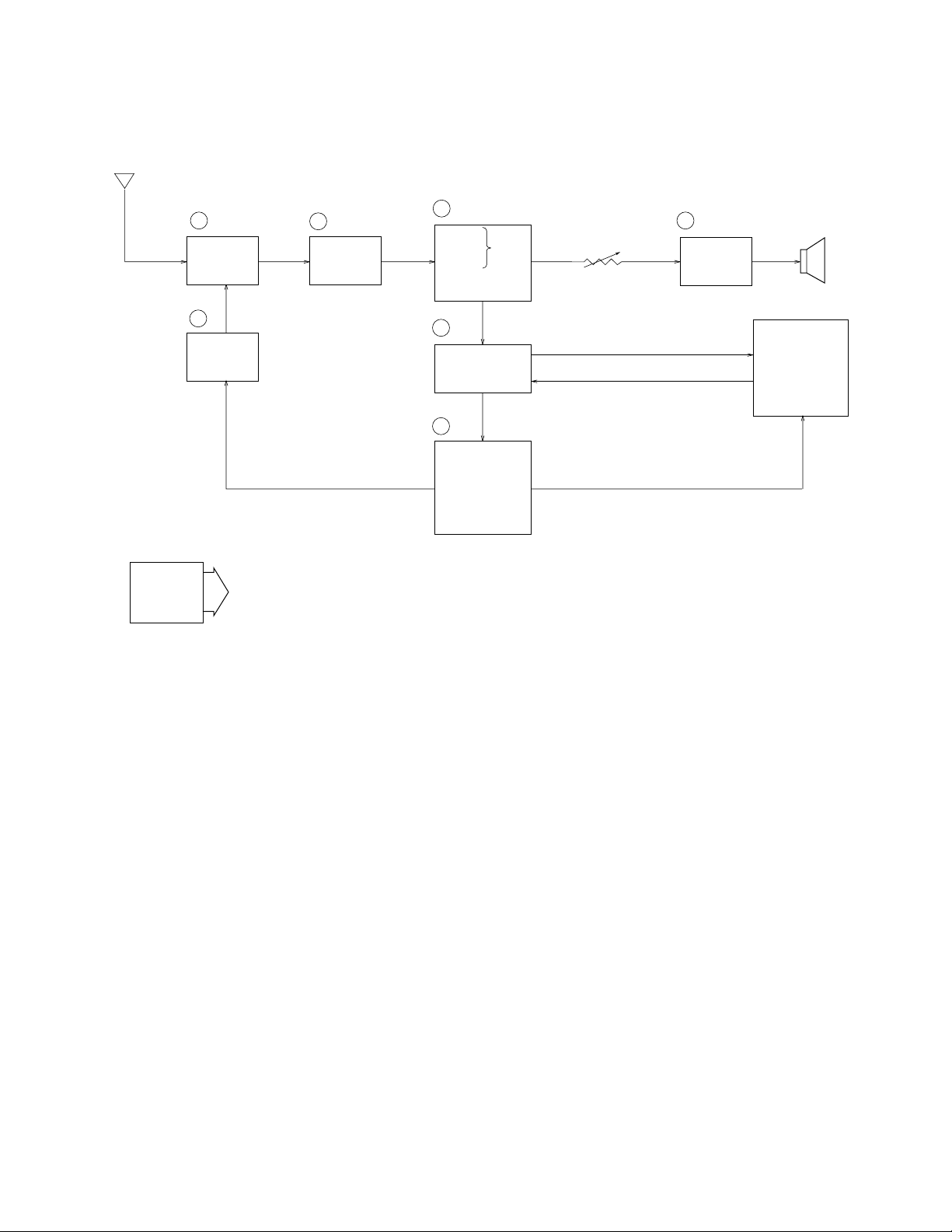
Antenna
BLOCK DIAGRAM
Power
Supply
1 TU200 2 Q200
IF Amp.Tuner
7
IC270
Tuning
Voltage
Generator
VCC2 (4.5±0.02V)
VCC7 (26.5~31.3V)
VCC6 (10.8~12.5V)
VEE1 (–8.5~–7.5V)
VEE2 (–19.8~–17.2V)
3 IC200
Video
Sound Det.
FM
AFT Circuit
AGC Circuit
5
6
Det
IC300
Chroma
Circuit
IC700
Display
Control
Auto-Tuning
Control
4 IC600 Speaker
VR600
Audio
Amp.
Volume
Control
LCD
1 — Color Tuner: TU200 TEPB5-02
Selects a desired radio wave and changes it to the video IF signal.
2 — Video IF Amp.: Q200 2SC4670
Amplifies the video IF signal output from the tuner TU by 10 times (20 dB).
3 — Video Det./Sound Det./FM Det./AFT/AGC: IC200 M51348FP
Eliminates the carrier wave in the video IF signal, and picks up the video signal and the sound IF signal.
Also, the sound signal is picked up from the sound IF signal by FM detection.
4 — Audio Amp.: IC600 NJM2070M
Sound amplification.
5 — Chroma Circuit: IC300 IR3P96B
Generates the tricolor (red, green, and blue) from the video signal.
6 — Display Control/ Auto-Tuning Control : IC700 MSM6770GS
Controls the display.
7 — Tuning Voltage Generator: IC270 BA10358F
Generates the tuning voltage with the tuning pulse (TU) output from 6.
— 2 —
Page 4
ADJUSTMENT
LINEAR PCB
Items To Be Adjusted
Item Measuring Instrument
VCC2-1 voltage setting Voltmeter
Video detection coil adjustment TV signal generator, pattern generator, oscilloscope,
low-pass filter
AFT coil adjustment Sweep generator, oscilloscope, voltmeter
Contrast adjustment TV signal generator, pattern generator, oscilloscope
AGC adjustment TV signal generator, pattern generator, IF levelmeter
Clock adjustment Voltmeter
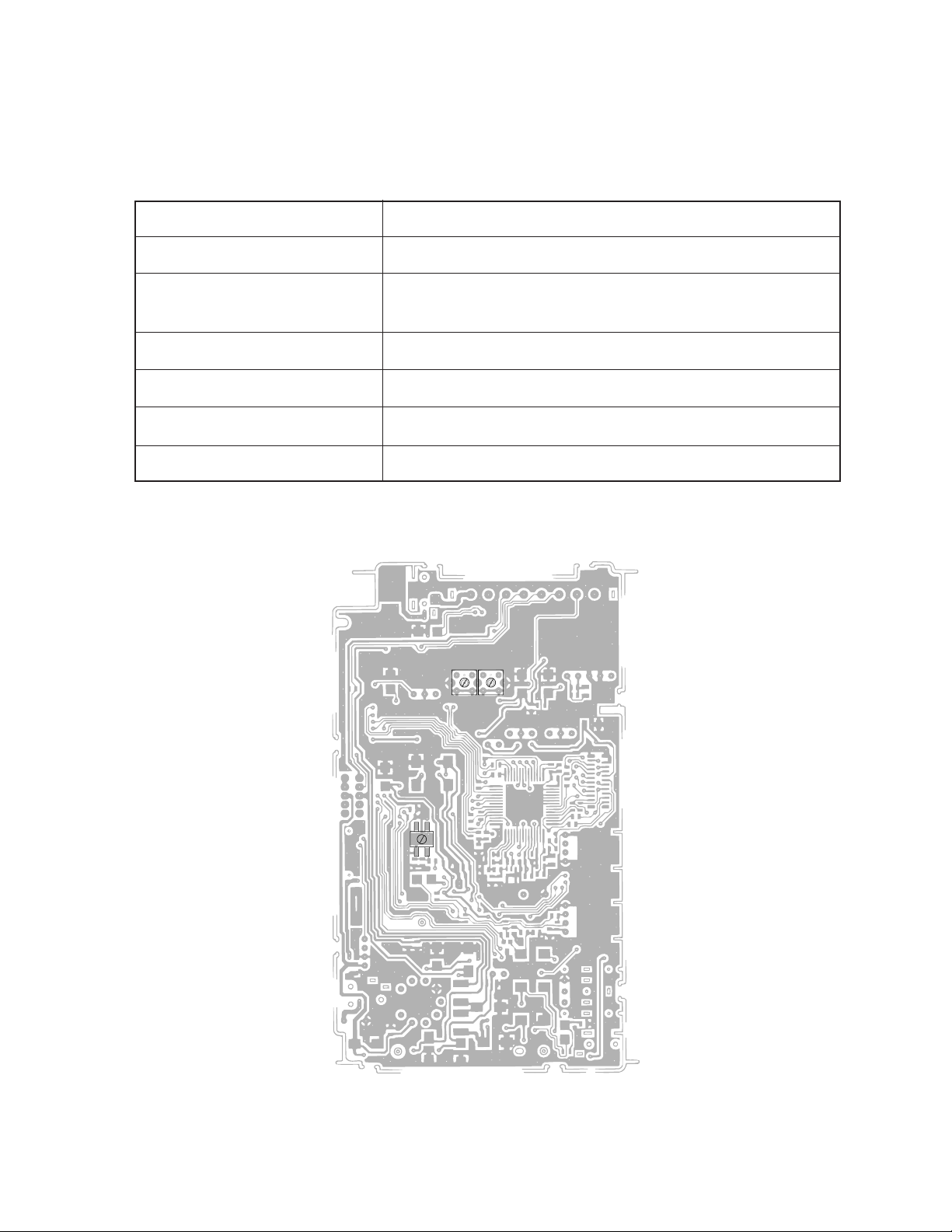
Adjustment And Test Point Locations
T300
T201
T200
Top View
— 3 —
Page 5
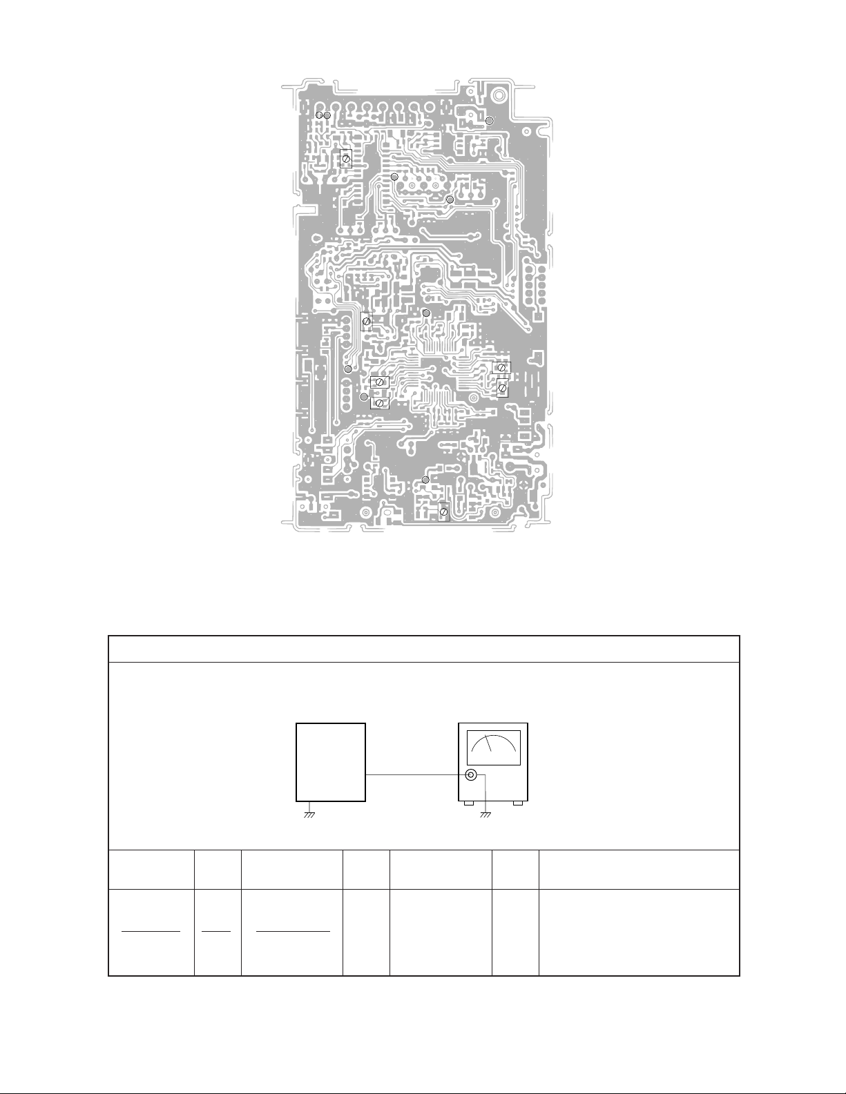
Pad IF
TP2
TP7
VR204
TP3
TP4
VR748
TP5
VR302
TP8
VR303
TP6
TP1
VR100
Bottom View
Equipment Connection / Adjustment Procedure
VCC2-1 Voltage Setting
TV-5100
Set
VR301
VR300
Voltmeter
Output
TP1
Input Input Input Output Output
Connection Point Signal Connection Point
Adjust Result
VR100
Voltmeter
— 4 —
TP1
Adjust for 4.50 ± 0.02 V
reading on voltmeter.
Page 6
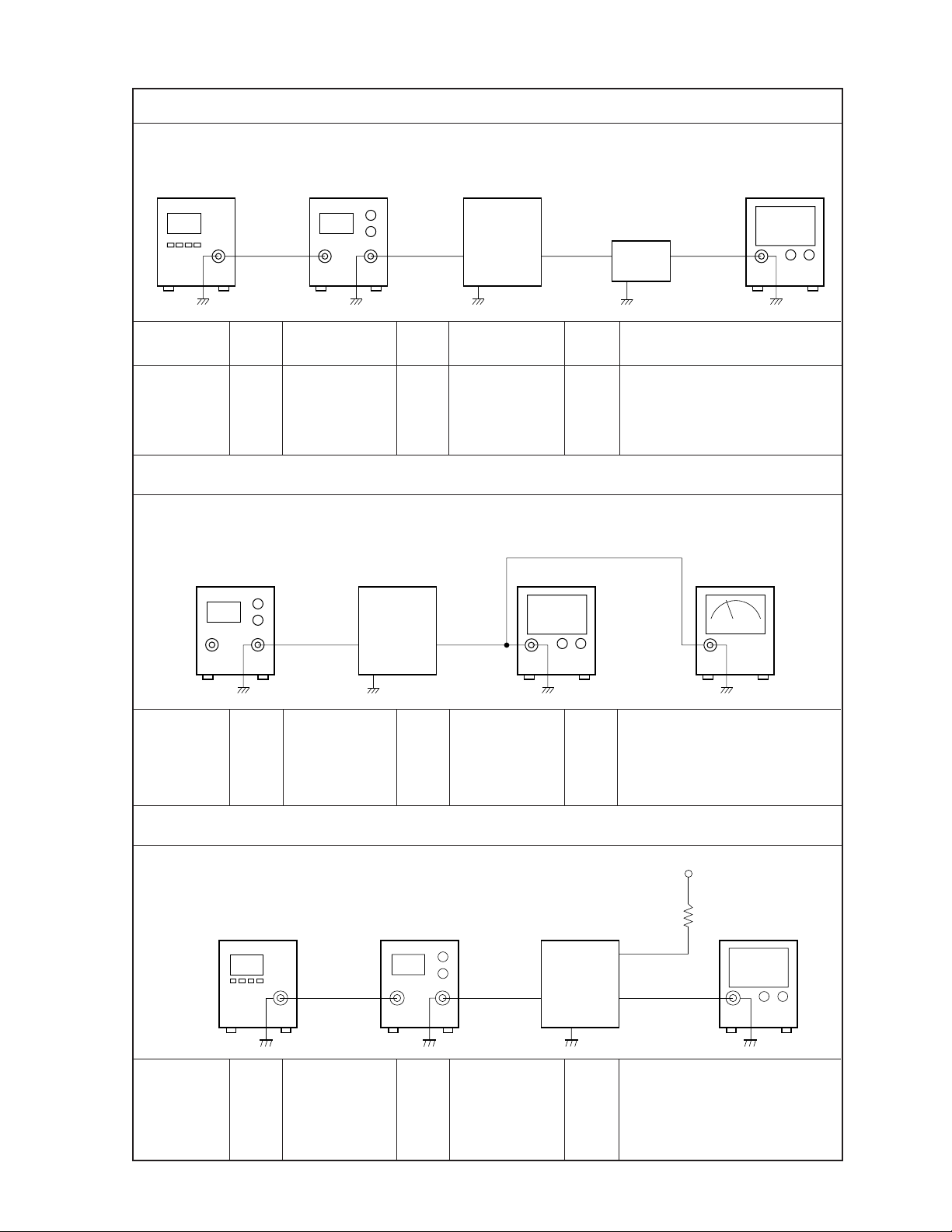
* Open soldering pad IF.
Pattern
generator
Signal
generator
Video Detection Coil Adjustment
TV-5100
Set
Input Output
TP2
TP3
Oscilloscope
Low-pass
filter
Input Input Input Output Output
Connection Point Signal Connection Point
Adjust Result
Pattern
generator
Signal
generator
TP2 T200 TP3
Color bar
39.5 MHz
48 ± 3 dBµ
Low-pass filter
Oscilloscope
AFT Coil Adjustment
* Open soldering pad IF.
Sweep
generator
Input
TP2
TV-5100
Set
Oscilloscope Voltmeter
Output
TP4
39.5±5 MHz
Sweep
generator
(Sweep) Marker:
TP2 T201 TP4
39.5 MHz
Voltmeter
Oscilloscope
70 dBµ
Adjust for DC level at mini-
Adjust for 1.4 ± 0.2 V reading
on voltmeter.
Confirm that the marker is at
the middle of S-curve on oscilloscope.
* Open soldering pad IF.
Pattern
generator
Pattern
generator
Signal
TP2 VR300 TP5
Color bar
39.5 MHz
70 dBµ
generator
Contrast Adjustment
Signal
generator
Input
TP2
Oscilloscope
— 5 —
TV-5100
Set
VCC2-3(5V)
10 kohm
Oscilloscope
CP327
Output
TP5
Adjust step form wave to read
2.6 ± 0.1 Vp-p.
Page 7
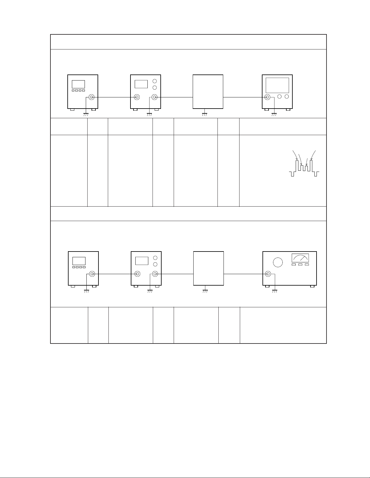
* Open soldering pad IF.
Pattern
generator
Signal
generator
Color, BCC Adjustment
TV-5100
Set
Oscilloscope
Input
TP2
Input Input Input Output Output
Connection Point Signal Connection Point
Pattern
generator
Signal
TP2 Oscilloscope TP5
Color bar
39.5 MHz
70 dBµ
Adjust Result
VR301
T300
generator
AGC Adjustment
Pattern
generator
Signal
generator
TV-5100
Set
Output
TP5
Adjust VR301 so that the
difference
Pulse A
between pulse
A and B is less
than 0.5 ± 0.1V.
Adjust T300 so
that the difference between
pulse C and D is less than
0.1V.
IF levelmeter
Pulse C
Pulse D
Pulse B
Pattern
generator
TV Signal
generator
Input
TP7
Color bar
TP7 VR204 IF levelmeter TP2
65 ± 5 dBµ
Output
TP2
Adjust for 84 ±1 dBµ
reading on the IF levelmeter
— 6 —
Page 8
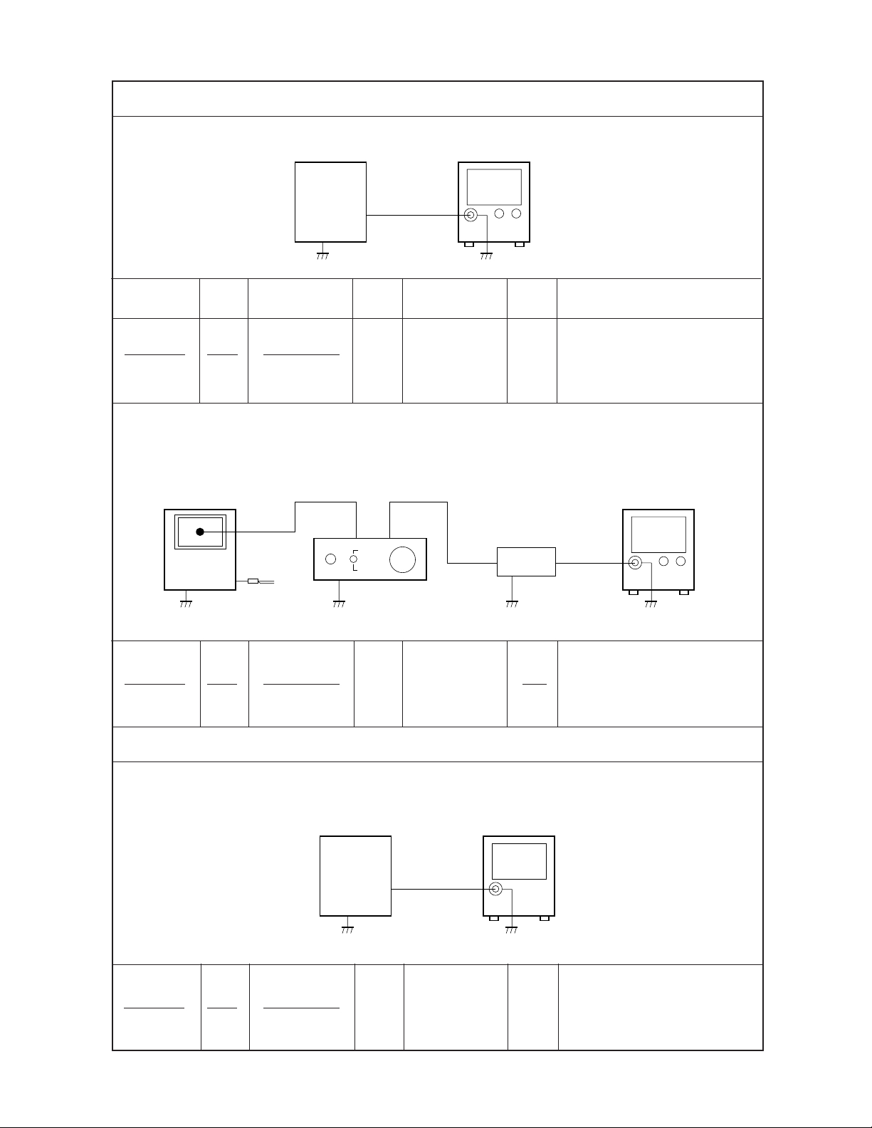
Vcom Adjustment
TV-5100
Set
Oscilloscope
Output
TP8
Input Input Input Output Output
Connection Point Signal Connection Point
Adjust Result
VR302
Oscilloscope TP8
VR303
* Place a photo diode on the middle of the display plate.
Photo senser amp.
TV-5100
Set
Photo
diode
ON
OFF
Band-pass
H
M
L
filter
Adjust VR302 so that squarewave to read 5.0 ±0.1V.
Adjust VR303 so that high level
of the square-wave is at
0.5±0.1V.
Oscilloscope
AV-C1
Photo sensor
amp.
VR303
Band pass filter
Oscilloscope
Free-running Frequency Adjustment
TV-5100
Set
Frequency
Counter
Output
TP6
VR748 TP6
Frequency
Counter
Adjust for ripple at minimum.
Adjust for a reading of 15.625 ±
0.1 KHz.
— 7 —
Page 9
PRINTED CIRCUIT BOARDS
TOP VIEWS
Linear
R290
SW100
C795
D180
ANT
JK200
C305
FU100
CN701
JK100
C100
C210
1
T
C202
T
TU200
F203
1
R706
R
701
R703
R324
R208
C242
GSRT
GRES
VGL
SRT
MCLK
CLR
R704
R702
JK250
C792
VSS2
VB
Vg
F200
L201
CN700
VR640
VR343
VCOM
VGH
GPCK
VSS1
VA
VC
VSL
VSH
VSS3
HCNT
1
T
T201
F203
T
C329
R781
C317 T300
C308
C160
C331
R780
C315
C306
R308
610D-L-B
C110
C162
AFT
R738
R739
C332 R747
C330
R339
L102L101
R727
R729
C771
R743
C717
T200
LLD
R728
IC700
R
R745 R744
C774
R353
Q300
C350
C156 C112
C116
C207
F202
F202
OM675
740
L760
C
772
1
R761
IC701
R748
H300
R350
C351
R351 R352
C603
C208
R222
F201
1
F201
R716
R715
1
L756
R323
R325
T100
C606
C130
C120
C114
C118
R600
JK600
BL
C925L950
C927
T950
— 8 —
Page 10

BOTTOM VIEWS
Linear
R201
R203
R205
R206
C238
C236
C240
VEE2
CP780
CP707
CP705
CP704
CP701
IF
CP115
R770
R705
SP
CP620
R620
HP
+
C254
1
R204
C248
CP702
R641
R642
C642
SP
IFIN
C239
C249
Q750
R759
CP774
CP769
CP769
CP719
+
–
CP339B
10
11
C233
C243
C794
C726
CP337G
C641
R777
C745
C783
C773
R749
CP750
R318
R319
R320
5
EAR
BS
R213
VR204
R225
C790
CP718
R758
VR748
R317
CP334
C334
C252
CP717
1
R607
BT
1
IC
200
11
VR303
R232
R640
C287
R230
R722
R725
IC
600
C793
CP724
C746
L749
R721
L780
R322
R231
R643
C217
R238
C789
R751
C630
C201
R286
VIDEO
C257
R229
AUDIO
R316
C328
C200
R270
C270
R285
C261
C264
R250
R228
CP768
C747
C333
C336
C335
VCC6
Vcc2-0
R606
TM100
R271
R272
C263 C262
R226
Q751
D715
C769
L740
C770
IR3P90B
C337
C338
C340
D110
R100
C105
8
C230
AGC
1
TU
ATT
C251
KDB
R736
CP
326
C318
IC300
C152
C154
D154
D100
R107
VR100
R246
C314
R331R330
C341
AFT
L303
R310
CP320
R329
D152
Q111
Q101
C271
IC270
C310
C343
D158
C158
Q270
R238
R266
Vcc2-2
L302
R734
C344
VR305
R332
R160
C299
C253
R732
R304
1
C150
C140
C161
L202
L300
R302
R110
D160
R247
C311
R309
R303
VR306
D150
R115
1
ANT
R275
R276
SyOUT
C782
VIDEO1
R733
R307
C
C304
R113
H/L
VEE1
309
Vcc2-1
C300
C145
R108
Q110
Vcc1-1
Vcc7
R306
VR301
R301
VR300
C180
3
R117
C137
R731
Vcc1
1
R738
BV
BU
Vcc2-1
1
DB
DB
DB
FU100
C185
+
BL
FU900
R795
Q950
R950
— 9 —
Q951
R953
SW701
R796
SW700
C796
FU901
Page 11

TOP VIEWS
BL PCB
WIRING DIAGRAM
41
Linear PCB
41
— 10 —
Page 12

ELECTRICAL PARTS LIST
Linear PCB No. 1
FOB Japan
N Item Code No. Parts Name Specification M N.R.Yen R
Unit Price
Capacitors
C100 2807 6595 Electrolytic ECE-V0JV101Z-P 10 33 C
C105 2895 0595 Tantalum ECST0JY225R 10 30 C
N C110 2803 6421 Electrolytic ECE-V1CA220SR 20 20 C
N C112 2807 6896 Electrolytic ECE-V1CA470S-P 20 23 C
C114 2807 6595 Electrolytic ECE-V0JV101Z-P 10 33 C
C116 2807 6595 Electrolytic ECE-V0JV101Z-P 10 33 C
N C118 2803 6421 Electrolytic ECE-V1CA220SR 20 20 C
N C120 2807 7169 Electrolytic ECE-V1VA220S-P 20 23 C
C130 2897 1099 Ceramic GR39Y5V103Z50PT 10 4 C
N C137 2897 2135 Ceramic UMK107B682K-T 20 4 C
C140 7103 5861 Ceramic GR39CH471J50PT 10 10 C
N C145 2845 4053 Ceramic 10N1HB152K-T1 20 3 C
C150 2897 1099 Ceramic GR39Y5V103Z50PT 10 4 C
C152 2897 1099 Ceramic GR39Y5V103Z50PT 10 4 C
C154 2897 1099 Ceramic GR39Y5V103Z50PT 10 4 C
C156 2892 0059 Ceramic GR40Y5V103Z50PT 10 9 C
C158 2897 1099 Ceramic GR39Y5V103Z50PT 10 4 C
C160 2892 0059 Ceramic GR40Y5V103Z50PT 10 9 C
C162 2897 1099 Ceramic GR39Y5V103Z50PT 10 4 C
N C180 2845 4473 Ceramic UMK212F104Z-T 20 4 C
N C200 2895 0630 Tantalum SK-1V104M-R 20 22 C
N C201 2895 0630 Tantalum SK-1V104M-R 20 22 C
N C202 2807 6791 Electrolytic ECE-V0JA470S-R 20 20 C
C205 2895 0189 Tantalum ECST0JY335R 10 30 C
N C207 2807 6791 Electrolytic ECE-V0JA470S-R 20 20 C
N C208 2807 6791 Electrolytic ECE-V0JA470S-R 20 20 C
C210 2807 6609 Electrolytic ECE-V1CA100S-R 1 19 C
N C217 2895 2030 Tantalum SK-1V474M-R 20 22 C
C230 2897 1099 Ceramic GR39Y5V103Z50PT 10 4 C
C236 2897 1099 Ceramic GR39Y5V103Z50PT 10 4 C
C237 2897 1099 Ceramic GR39Y5V103Z50PT 10 4 C
N C239 2845 4921 Ceramic 10N1HCH160J-T1 20 3 C
C240 2897 1099 Ceramic GR39Y5V103Z50PT 10 4 C
C243 2897 1099 Ceramic GR39Y5V103Z50PT 10 4 C
C245 2897 1134 Ceramic GR39W5R103K50PT 10 5 C
C246 2897 1099 Ceramic GR39Y5V103Z50PT 10 4 C
C247 2897 1099 Ceramic GR39Y5V103Z50PT 10 4 C
C248 2897 1099 Ceramic GR39Y5V103Z50PT 10 4 C
C249 2897 1057 Ceramic GR40Y5V474Z16PT 10 16 C
C252 2897 1141 Ceramic GR39W5R223K25PT 20 7 C
N C257 2845 4081 Ceramic 10N1HCH270J-T1 20 3 C
C259 2897 1134 Ceramic GR39W5R103K50PT 10 5 C
N C261 2897 2065 Ceramic GR39PH560G50PT 20 9 C
C262 2897 1099 Ceramic GR39Y5V103Z50PT 10 4 C
N C263 2897 2065 Ceramic GR39PH560G50PT 20 9 C
N C264 2845 4165 Ceramic 10N1HCH0R5C-T1 20 3 C
C270 2897 1134 Ceramic GR39W5R103K50PT 10 5 C
C271 2897 1365 Ceramic GR39Y5V473Z50PT 10 5 C
N C287 2845 4935 Ceramic 10N1HB332K-T1 20 3 C
C299 2897 1099 Ceramic GR39Y5V103Z50PT 10 4 C
C300 2897 1099 Ceramic GR39Y5V103Z50PT 10 4 C
Notes: N – New parts
M – Minimum order/supply quantity
R – Rank
— 11 —
Page 13

Linear PCB No. 2
FOB Japan
N Item Code No. Parts Name Specification M N.R.Yen R
Unit Price
C301 2897 1099 Ceramic GR39Y5V103Z50PT 10 4 C
C302 2897 1358 Ceramic GR39Y5V104Z25PT 10 7 C
C303 2897 1099 Ceramic GR39Y5V103Z50PT 10 4 C
N C304 2845 4998 Ceramic 10N1HB681K-T1 20 3 C
N C305 2807 6896 Ceramic ECE-V1CA470S-P 20 23 C
C306 2897 1099 Ceramic GR39Y5V103Z50PT 10 4 C
C307 2897 1358 Ceramic GR39Y5V104Z25PT 10 7 C
C308 2807 6609 Electrolytic ECE-V1CA100S-R 1 19 C
C309 2897 1099 Ceramic GR39Y5V103Z50PT 10 4 C
C310 2895 0126 Tantalum ECST1CY105R 10 27 C
N C311 2845 4081 Ceramic 10N1HCH270J-T1 20 3 C
C312 2897 1127 Ceramic GR39W5R222K50PT 10 4 C
N C313 2845 5012 Ceramic 10N1HF153Z-T1 20 4 C
N C314 2807 6896 Electrolytic ECE-V1CA470S-P 20 23 C
C315 2897 1099 Ceramic GR39Y5V103Z50PT 10 4 C
C316 2897 1099 Ceramic GR39Y5V103Z50PT 10 4 C
N C318 2897 1792 Ceramic TMK107F104Z-T 10 4 C
N C319 2897 1792 Ceramic TMK107F104Z-T 10 4 C
C320 2897 1099 Ceramic GR39Y5V103Z50PT 10 4 C
C321 2897 1099 Ceramic GR39Y5V103Z50PT 10 4 C
C322 2897 1365 Ceramic GR39Y5V473Z50PT 10 5 C
N C323 2897 1792 Ceramic TMK107F104Z-T 10 4 C
C324 2897 1099 Ceramic GR39Y5V103Z50PT 10 4 C
N C325 2897 1337 Ceramic GR39CH160J50PT 20 4 C
C326 2897 1099 Ceramic GR39Y5V103Z50PT 10 4 C
C327 2895 0133 Tantalum ECST1EY474R 10 27 C
C328 2897 1099 Ceramic GR39Y5V103Z50PT 10 4 C
N C329 2807 7176 Electrolytic 10RV2-47-T 20 23 C
C330 2897 1099 Ceramic GR39Y5V103Z50PT 10 4 C
N C331 2828 5553 Electrolytic 16RV2-47-T 20 23 C
C332 2897 1099 Ceramic GR39Y5V103Z50PT 10 4 C
N C334 2895 1596 Tantalum ECST1CY475R 10 27 C
C335 2897 1099 Ceramic GR39Y5V103Z50PT 10 4 C
C336 2897 1358 Ceramic GR39Y5V104Z25PT 10 7 C
C337 2897 1358 Ceramic GR39Y5V104Z25PT 10 7 C
C338 2897 1358 Ceramic GR39Y5V104Z25PT 10 7 C
C339 2897 1099 Ceramic GR39Y5V103Z50PT 10 4 C
C340 2897 1099 Ceramic GR39Y5V103Z50PT 10 4 C
C341 2897 1099 Ceramic GR39Y5V103Z50PT 10 4 C
C342 2897 1099 Ceramic GR39Y5V103Z50PT 10 4 C
C343 2897 1099 Ceramic GR39Y5V103Z50PT 10 4 C
C344 2897 1099 Ceramic GR39Y5V103Z50PT 10 4 C
C350 2807 6560 Electrolytic 6.3RV2BP-47-T 10 37 C
C351 2897 1099 Ceramic GR39Y5V103Z50PT 10 4 C
C600 2807 6602 Electrolytic ECE-V0JA220S-R 10 19 C
N C603 2807 6742 Electrolytic ECE-V0JA101S-P 20 23 C
N C606 2807 6742 Electrolytic ECE-V0JA101S-P 20 23 C
C641 2897 1120 Ceramic GR39W5R102K50PT 10 4 C
N C642 2897 2128 Ceramic TMK212B104K-T 20 9 C
C717 2897 1099 Ceramic GR39Y5V103Z50PT 10 4 C
N C725 2895 2023 Tantalum SK-1V224M-R 20 22 C
N C746 2897 1792 Ceramic TMK107F104Z-T 20 4 C
C751 2897 1099 Ceramic GR39Y5V103Z50PT 10 4 C
C769 2897 1099 Ceramic GR39Y5V103Z50PT 10 4 C
Notes: N – New parts
M – Minimum order/supply quantity
R – Rank
— 12 —
Page 14

Linear PCB No. 3
FOB Japan
N Item Code No. Parts Name Specification M N.R.Yen R
Unit Price
N C770 2845 4802 Ceramic EMK316F225Z-T 20 16 C
N C771 2845 3794 Ceramic 10N1HB222K-T1 20 3 C
C772 2897 1099 Ceramic GR39Y5V103Z50PT 10 4 C
N C773 2845 4802 Ceramic EMK316F225Z-T 20 16 C
C774 2897 1099 Ceramic GR39Y5V103Z50PT 10 4 C
N C781 2897 1722 Ceramic UMK107B562K-T 20 4 C
N C783 2845 4802 Ceramic EMK316F225Z-T 20 16 C
N C786 2845 4081 Ceramic 10N1HCH270J-T1 20 3 C
N C787 2897 2030 Ceramic GR39UJ270J50PT 20 4 C
C788 2897 1099 Ceramic GR39Y5V103Z50PT 10 4 C
N C789 2845 5005 Ceramic 10N1HF102Z-T1 20 4 C
N C790 2897 1792 Ceramic TMK107F104Z-T 20 4 C
N C791 2897 1792 Ceramic TMK107F104Z-T 20 4 C
C792 2897 0273 Ceramic GR42-6Y5V104Z25PT 10 12 C
N C793 2897 1792 Ceramic TMK107F104Z-T 20 4 C
N C794 2897 1792 Ceramic TMK107F104Z-T 20 4 C
Connector
N CN700 3501 8316 Connector 52559-2090 5 70 C
Diodes
D100 7101 1194 Chip MA111(TX) 10 18 C
D110 2315 0158 Chip, Zener MA3051-L(TX) 10 30 C
D150 7101 1194 Chip MA111(TX) 10 18 C
D152 2390 1379 Chip, Schottoky MA729-(TX) 10 30 C
D154 2390 1379 Chip, Schottoky MA729-(TX) 10 30 C
D158 7101 1194 Chip MA111(TX) 10 18 C
D160 2390 1470 Chip MA143A-(TX) 10 16 C
D180 2390 1190 Chip ERA15-01Y 20 9 C
D715 2390 1379 Chip, Schottoky MA729-(TX) 10 30 C
Filters and Traps
F200 3025 0210 SAW Filter SAF39.5MZ60Z 1 150 C
F201 3025 0721 SIF Filter SFSL6.0MDB12 1 33 C
F202 3851 1141 Ceramic Discriminator CDSL6.0MC30B12 1 48 C
F203 3851 0553 SIF Trap TPS6.0MB 1 30 C
Fuse
N FU100 3632 0469 Fuse PI-251001(F10)1A 5 52 B
Oscillator
H300 2590 1239 Crystal HC-49 1 110 C
ICs
IC200 2114 1827 Linear M51348FP-T1 1 190 B
IC270 2116 0119 OP AMP BA10358F-T1 10 39 B
N IC300 2114 3479 Linear IR3P96-1 1 670 B
IC600 2114 2464 Linear NJM2070M-T1 1 65 B
IC700 2011 7784 LSI MSM6770GS-VK-675 1 300 B
IC701 2114 3458 IC S-81230SG-QB-T1 1 50 B
Jacks
JK100 3501 8281 Jack HEC0811-010010 10 30 C
JK200 3501 5439 Jack HSJ1456-01-210 1 27 C
JK250 3501 3773 Jack HSJ6063-01-410 1 88 C
JK600 3501 5439 Jack HSJ1456-01-210 1 27 C
Inductors
L101 3013 1022 Chip NLC453232-101K-TP 1 28 C
N L102 3013 1638 Chip NL453232-331K-TP 20 27 C
L200 3013 1393 Chip LK2125-R82K-TP 1 26 C
N L202 3013 1400 Chip LK2125-120K-TP 1 30 C
Notes: N – New parts
M – Minimum order/supply quantity
R – Rank
— 13 —
Page 15

Linear PCB No. 4
FOB Japan
N Item Code No. Parts Name Specification M N.R.Yen R
Unit Price
L300 3013 1092 Chip NLC322522-470K-TP 1 28 C
L301 3013 1204 Chip MLF2012C330K-TP 1 29 C
L302 3013 1092 Chip NLC322522-470K-TP 1 28 C
L303 3013 1092 Chip NLC322522-470K-TP 1 28 C
L740 3013 1043 Chip NLC322522-101K-TP 1 28 C
L749 3013 1043 Chip NLC322522-101K-TP 1 28 C
L753 3013 1043 Chip NLC322522-101K-TP 1 28 C
L756 3013 1204 Chip MLF2012C330K-TP 1 29 C
L780 3013 1043 Chip NLC322522-101K-TP 1 28 C
Transistors
Q101 2253 0133 Chip 2SD1819A-R 10 12 B
Q110 2253 0133 Chip 2SD1819A-R 10 12 B
Q111 2253 0308 Chip 2SD1119-R(TX) 10 37 B
Q200 2252 0994 Chip 2SC4670-(TX) 10 23 C
Q300 2251 0189 Chip 2SB1218A-R(TX) 10 10 C
Q750 2251 0189 Chip 2SB1218A-R(TX) 10 10 C
Resistors
R100 2795 3360 Chip jumper MCR03EZHJ000 20 2 C
R105 2797 1995 Chip resistor ERJ-3GEYJ332V 20 10 C
R107 2797 1827 Chip resistor ERJ-3GEYJ333V 20 2 C
R108 2797 2464 Chip resistor ERJ-3GEYJ274V 20 2 C
R110 2791 1131 Chip resistor ERJ-6GEYJ271V 20 3 C
R113 2797 2044 Chip resistor ERJ-3GEYJ222V 20 2 C
R115 2797 1813 Chip resistor ERJ-3GEYJ101V 20 2 C
R117 2795 3360 Chip jumper MCR03EZHJ000 20 2 C
R160 2791 1692 Chip resistor ERJ-6GEYJ680V 20 3 C
N R200 2797 3689 Chip resistor ERJ-3GEYJ220V 20 2 C
R201 2797 1813 Chip resistor ERJ-3GEYJ101V 20 2 C
R202 2797 2443 Chip resistor ERJ-3GEYJ682V 20 2 C
R203 2797 2422 Chip resistor ERJ-3GEYJ272V 20 2 C
R204 2797 2401 Chip resistor ERJ-3GEYJ681V 20 2 C
N R205 2797 3689 Chip resistor ERJ-3GEYJ220V 20 2 C
R206 2795 3360 Chip jumper MCR03EZHJ000 20 2 C
R207 2797 2674 Chip resistor ERJ-3GEYJ151V 20 10 C
R208 2797 2422 Chip resistor ERJ-3GEYJ272V 20 2 C
R209 2797 2303 Chip resistor ERJ-3GEYJ103V 20 2 C
R210 2797 2065 Chip resistor ERJ-3GEYJ472V 20 2 C
R211 2797 1764 Chip resistor MCR03EZHJ104 20 2 C
R212 2797 2044 Chip resistor ERJ-3GEYJ222V 20 2 C
R214 2797 1862 Chip resistor ERJ-3GEYJ473V 20 2 C
R222 2797 2373 Chip resistor ERJ-3GEYJ470V 20 2 C
R223 7102 2193 Chip resistor ERJ-3GEYJ184V 20 2 C
R225 2797 2408 Chip resistor ERJ-3GEYJ821V 20 2 C
R227 2795 3360 Chip jumper MCR03EZHJ000 20 2 C
R229 2797 2002 Chip resistor ERJ-3GEYJ471V 20 2 C
R230 2797 2093 Chip resistor ERJ-3GEYJ271V 20 10 C
R231 2797 2436 Chip resistor ERJ-3GEYJ562V 20 2 C
R236 2797 2464 Chip resistor ERJ-3GEYJ274V 20 2 C
R240 2797 2030 Chip resistor ERJ-3GEYJ223V 20 2 C
R241 2797 2457 Chip resistor ERJ-3GEYJ124V 20 2 C
R242 2795 3360 Chip jumper MCR03EZHJ000 20 2 C
R246 2797 2380 Chip resistor ERJ-3GEYJ331V 20 2 C
R247 2797 2044 Chip resistor ERJ-3GEYJ222V 20 2 C
R250 2797 2303 Chip resistor ERJ-3GEYJ103V 20 2 C
Notes: N – New parts
M – Minimum order/supply quantity
R – Rank
— 14 —
Page 16

Linear PCB No. 5
FOB Japan
N Item Code No. Parts Name Specification M N.R.Yen R
Unit Price
R270 2797 1827 Chip resistor ERJ-3GEYJ333V 20 2 C
R271 2797 2884 Chip resistor ERJ3GEYF333V 20 3 C
R272 2797 2429 Chip resistor ERJ3GEYF392V 20 2 C
R285 2797 2093 Chip resistor ERJ-3GEYJ271V 20 10 C
R286 2797 1764 Chip resistor MCR03EZHJ104 20 2 C
R290 2795 3360 Chip jumper MCR03EZHJ000 20 2 C
R300 2797 2681 Chip resistor ERJ-3GEYJ393V 20 2 C
R301 2797 1827 Chip resistor ERJ-3GEYJ333V 20 2 C
N R302 7720 1491 Chip resistor ERJ-3GEYJ106V 20 2
R303 2797 1820 Chip resistor ERJ-3GEYJ105V 20 2 C
R305 2797 2856 Chip resistor ERJ-3GEYJ823V 20 2 C
R306 2797 2226 Chip resistor ERJ-3GEYJ563V 20 2 C
N R307 2797 3787 Chip resistor ERJ3GEYF272V 20 3 C
R309 2797 1820 Chip resistor ERJ-3GEYJ105V 20 2 C
R310 2797 2093 Chip resistor ERJ-3GEYJ271V 10 10 C
R311 2797 2401 Chip resistor ERJ-3GEYJ681V 10 2 C
R312 2797 1827 Chip resistor ERJ-3GEYJ333V 20 2 C
R313 2795 3360 Chip jumper MCR03EZHJ000 20 2 C
N R315 2797 3353 Chip resistor ERJ-3GEYF393V 20 3 C
R316 2797 2884 Chip resistor ERJ-3GEYF333V 20 3 C
R317 2797 2436 Chip resistor ERJ-3GEYJ562V 20 2 C
R318 2797 2247 Chip resistor ERJ-3GEYJ822V 20 2 C
R319 2797 1827 Chip resistor ERJ-3GEYJ333V 20 2 C
R320 2797 1827 Chip resistor ERJ-3GEYJ333V 20 2 C
R321 2797 2303 Chip resistor ERJ-3GEYJ103V 20 2 C
R322 2797 2681 Chip jumper ERJ-3GYJY393V 20 2 C
R323 2797 1827 Chip resistor ERJ-3GEYJ333V 20 2 C
R324 2797 2303 Chip resistor ERJ-3GEYJ103V 20 2 C
N R325 2797 3451 Chip resistor ERJ-3GEYJ203V 20 2 C
N R326 2797 3682 Chip resistor ERJ-3GEYF183V 20 3 C
N R327 2797 3444 Chip resistor ERJ-3GEYF203V 20 3 C
R328 2797 2891 Chip resistor ERJ-3GEYF363V 20 3 C
R329 2797 2905 Chip resistor ERJ-3GEYF513V 10 3 C
R330 2797 2877 Chip resistor ERJ-3GEYF243V 20 3 C
R331 2797 3220 Chip resistor ERJ-3GEYF273V 10 3 C
R350 2797 1813 Chip resistor ERJ-3GEYJ101V 20 2 C
R351 2797 2030 Chip resistor ERJ3GEYJ223V 10 2 C
R352 2797 2436 Chip resistor ERJ-3GEYJ562V 20 2 C
R353 2797 2394 Chip resistor ERJ-3GEYJ561V 20 2 C
R600 2797 2674 Chip resistor ERJ-3GEYJ151V 10 10 C
N R601 2797 2527 Chip resistor ERJ-3GEYJ512V 20 2 C
R606 2795 0294 Chip jumper MCR18EZHJ000 20 3 C
R620 2791 0696 Chip resistor ERJ-6GEYJ470 20 4 C
R640 2797 1855 Chip resistor ERJ-3GEYJ102V 20 2 C
R642 2795 3360 Chip jumper MCR03EZHJ000 20 2 C
R643 2797 1988 Chip resistor ERJ-3GEYJ183V 20 2 C
R701 2797 2303 Chip resistor ERJ-3GEYJ103V 20 2 C
R702 2797 2303 Chip resistor ERJ-3GEYJ103V 20 2 C
R703 2797 2303 Chip resistor ERJ-3GEYJ103V 20 2 C
R704 2797 2303 Chip resistor ERJ-3GEYJ103V 20 2 C
R705 2797 2303 Chip resistor ERJ-3GEYJ103V 20 2 C
R706 2797 2303 Chip resistor ERJ-3GEYJ103V 20 2 C
R707 2797 2303 Chip resistor ERJ-3GEYJ103V 20 2 C
R714 2795 3360 Chip jumper MCR03EZHJ000 20 2 C
Notes: N – New parts
M – Minimum order/supply quantity
R – Rank
— 15 —
Page 17

Linear PCB No. 6
FOB Japan
N Item Code No. Parts Name Specification M N.R.Yen R
Unit Price
R716 2795 3360 Chip jumper MCR03EZHJ000 20 2 C
R719 2795 3360 Chip jumper MCR03EZHJ000 20 2 C
R721 2795 3360 Chip jumper MCR03EZHJ000 20 2 C
R724 2795 3360 Chip jumper MCR03EZHJ000 20 2 C
R727 2797 2065 Chip resistor ERJ-3GEYJ472V 20 2 C
N R728 2797 3773 Chip resistor ERJ-3GEYJ511V 20 2 C
R731 2797 2065 Chip resistor ERJ-3GEYJ472V 20 2 C
R733 2797 1855 Chip resistor ERJ-3GEYJ102V 20 2 C
R734 2797 2065 Chip resistor ERJ-3GEYJ472V 20 2 C
R736 2797 2065 Chip resistor ERJ-3GEYJ472V 20 2 C
R737 2797 2065 Chip resistor ERJ-3GEYJ472V 20 2 C
R738 2797 2065 Chip resistor ERJ-3GEYJ472V 20 2 C
R739 2797 2016 Chip resistor ERJ-3GEYJ225V 20 2 C
N R740 2797 3766 Chip resistor ERJ-3GEYF394V 20 3 C
N R741 2797 2527 Chip resistor ERJ-3GEYJ512V 20 2 C
R748 2797 2450 Chip resistor ERJ-3GEYJ153V 20 2 C
R749 2797 2436 Chip resistor ERJ-3GEYJ562V 20 2 C
R750 2797 1988 Chip resistor ERJ-3GEYJ183V 20 2 C
R751 2797 2443 Chip resistor ERJ-3GEYJ682V 20 2 C
R756 2797 1855 Chip resistor ERJ-3GEYJ102V 20 2 C
R757 2797 1855 Chip resistor ERJ-3GEYJ102V 20 2 C
N R758 2797 3353 Chip resistor ERJ-3GEYF393V 20 3 C
R759 2797 2898 Chip resistor ERJ-3GEYF473V 20 3 C
R760 2797 1876 Chip resistor MCR03EZHJ224 20 2 C
R761 2797 1876 Chip resistor MCR03EZHJ224 20 2 C
R770 2797 1764 Chip resistor MCR03EZHJ104 20 2 C
R777 2795 3360 Chip jumper MCR03EZHJ000 20 2 C
R780 2795 3360 Chip jumper MCR03EZHJ000 20 2 C
Switch
SW100 3412 0938 Switch ESD-11V231 1 45 C
Coils and Converter
N T100 3065 0476 DC-DC Converter LC12U-32 5 73 C
N T200 3841 1260 Coil S5E-05 5 73 C
N T201 3841 1253 Coil S5E-04 5 73 C
N T300 3841 1267 Coil 5CDM-01 1 110 C
Thermister
TM100 2775 1085 Chip 157-102-53031-TP 1 26 C
Tuner
TU200 1013 5525 Tuner TEPB5-02 1 820 C
Variable Resistor
N VR100 2775 1645 Semi-Fixed Resistor EVM-1XSX50B23 20 28 C
N VR204 2775 1484 Semi-Fixed Resistor EVM-1XSX50B24 20 28 C
N VR300 2775 1484 Semi-Fixed Resistor EVM-1XSX50B24 20 28 C
N VR301 2775 1484 Semi-Fixed Resistor EVM-1XSX50B24 20 28 C
N VR302 2775 1484 Semi-Fixed Resistor EVM-1XSX50B24 20 28 C
N VR303 2775 1491 Semi-Fixed Resistor EVM-1XSX50B54 20 28 C
N VR304 2765 0632 Volume RK09H11T20KB 5 64 C
VR640 2765 0462 Volume RK09H11T50KB 5 80 C
N VR748 2775 1477 Semi-Fixed Resistor EVM-1XSX50B14 20 28 C
Notes: N – New parts
M – Minimum order/supply quantity
R – Rank
— 16 —
Page 18

BL PCB
FOB Japan
N Item Code No. Parts Name Specification M N.R.Yen R
Unit Price
Capacitors
C796 2892 0059 Chip GR40Y5V103Z50PT 10 9 C
C925 2825 0392 TF ECQ-V1H154JL 10 19 C
N C927 2813 3472 Ceramic DE0705SL820J2K 20 13 C
Connector
CN702 3501 7182 Connector 52287-0411 1 22 C
Fuses
FU900 3632 0308 Temperature EYP-1BF102L 1 27 B
FU901 3632 0308 Temperature EYP-1BF102L 1 27 B
Coil
L950 3013 0756 Choke RCH-875-101K 5 55 C
Lamp
LA900 3851 1337 Fluorescent 8.61AD1P2-CA4 1 340 B
Transistors
Q950 2253 0308 Transistor 2SD1119-R(TX) 10 37 B
Q951 2253 0308 Transistor 2SD1119-R(TX) 10 37 B
Resistors
R795 2791 0305 Chip ERJ-6GEYJ472V 20 3 C
R796 2791 0305 Chip ERJ-6GEYJ472V 20 3 C
R950 2792 0500 Chip MCR18EZHJ471 20 2 C
R953 2792 0110 Chip ERJ-6GEYOR00V 20 3 C
Switches
N SW700 3412 1239 Switch SKHHAJ 20 12 C
N SW701 3412 1239 Switch SKHHAJ 20 12 C
Transformer
N T950 3012 1141 Inverter trans EW12H-01-CU 1 120 B
Notes: N – New parts
M – Minimum order/supply quantity
R – Rank
— 17 —
Page 19

MECHANICAL PARTS LIST
FOB Japan
N Item Code No. Parts Name Specification Q N.R.Yen R
Unit Price
N 1 6609 2004 Speaker ass'y K412107*1 1 100 C
2 6607 4720 Cushion A-K614 K410316-7 1 7 C
N 3 6609 1530 Battery spring A-K610 K412012-1 10 35 C
N 4 6609 1520 Flat cable A-K610 K311586-1 1 29 C
5 6601 1700 Insulation tape A-K60 K4117-3 2 3 C
N 6 6630 5552 BL ass'y K211264*1 1 2,010 B
N 6-1 6609 2070 Shield case E-K610 K311634-1 1 28 C
N 6-2 6609 2080 Insulation plate B-K610 K41212-1 1 6 C
6-3 6607 0690 Insulation plate D-K508 K410441-3 1 7 C
6-4 6606 6201 Adhesive tape C-K502 K410903A-3 1 3 C
N 6-5 6609 2240 Shield case F-K610 K311674-1 1 26 C
N 6-6 6609 1330 Shield case C-K610 K311528-1 1 40 C
N 6-7 6609 1350 Reflection tape A-K610 K412014-1 1 13 C
N 6-8 6609 1340 Shield case D-K610 K311529-1 1 43 C
6-9 3851 1337 Fluorescent lamp 8.61AD1P2-CA4 1 340 B
6-10 3632 0308 Temperature fuse EYP-1BF102L 2 27 B
N 7 6630 5683 Battery cover K412106*1 1 520 C
8 6609 1320 Switch knob A-K610 K311527-1 1 20 C
N 9 6630 5754 Upper case ass'y K211263*3 1 630 C
N 9-1 6020 7658 Battery spring B1 G513 P408A-1 1 25 C
9-2 6606 4920 Battery spring C-K603 K410883-1 1 14 C
9-3 6020 7666 Battery spring B2 G513 P409A-1 1 23 C
N 9-4 6609 1400 Blind tape A-K610 K412066-1 1 16 C
N 9-5 6609 1390 Adhesive tape A-K610 K412015-1 1 18 C
10 6609 1360 Tuning button A-K610 K311521-1 1 20 C
N 11 6609 1480 Adhesive tape B-K610 K412016-1 2 15 C
N 12 6609 1490 Insulation plate A-K610 K412018-1 1 8 C
N 13 2725 0966 Display Unit TAD18T1001NB 1 4,000 B
N 14 6609 1370 Earth plate A-K610 K412013-1 1 30 C
N 15 6609 1410 Spacer for Display A-K610 K211183-1 1 55 C
N 16 6609 1270 Lower case A-K610 K110739-1 1 120 C
N 17 6606 2130 Stand A-K331 K310518-1 1 36 C
18 3851 1470 Rod antenna VR70100GA 1 180 C
N 19 6630 5685 PCB-K610D-L ass'y K211312*1 1 10,880 B
19-1 6604 7630 Insulation plate A-K332 K4670-17 1 3 C
N 19-2 6603 7100 Insulation plate B-K420 K4330-16 1 2 C
N 20 6609 2460 Display plate DAM-K610 K412011-3 1 160 C
N 21 6609 2470 Rating plate DAM-K610 K412010-3 1 32 C
22 5112 0868 Tapping screw (+) BT3, 1.7x5Bk 6 3 X
23 5860 0301 Tapping screw (+) BT3, 1.7x5Ni 3 3 X
24 5860 0805 Tapping screw (+) BT3,1.7x10Bk 2 3 X
25 5860 1477 Tapping screw (+) BT3,1.7x3.5Bk 1 1 X
N 26 6609 1290 Screw A-K610 K412031-1 1 3 X
Notes: N – New parts
M – Minimum order/supply quantity
R – Rank
— 18 —
Page 20

EXPLODED VIEW / DISASSEMBLY
22
10
6-9
20
9
9-5
11
12
13
23
14
25
11
1
15
9-3
9-1
8
22
7
9-4
6
6-1
6-2
22
6-10
5
4
9-2
6-4
3
2
6-6
6-9
6-3
6-5
6-7
6-8
19
19-2
18
22
Disassembly
1. Slide the battery cover 7.
2. Remove five screws L, N and P.
3. Remove the rod antenna H.
4. Remove the lower case F.
5
19-1
16
24
26
24
17
21
— 19 —
Page 21

IC AND TRANSISTOR LEAD IDENTIFICATION AND
INTERNAL CIRCUITRY
TRANSISTORS
IC/LSI
C
BEC
2SD1119
IC200 IC270
M51348FP BA10358F
BE
2SB1218A 2SC4760
2SD1819A DTA143TUW
DTC144EUW
C
IF AGC OUT 1 24 IF AGC ADJ
IF AGC IN 2 23 SyOUT
RF AGC 3 22 SyIN
AGCDL 4 21 AFTC
VCCv 5 20 LLD
IFIN 6 19 LLD
IFIN 7 18 VIDEO
GNDv 8 17 AFT
VCCs 9 16 SIFOUT
SIFIN 10 15 FMD
FB 11 14 ATT
GNDs 12 13 AUDIO
OUT1 1 8 VCC
– IN 2 7 OUT2
+IN 3 6 IN2–
GND 4 5 IN2+
IC600
NJM2070M
NC 1 8 NC
+IN 2 7 VCC
–IN 3 6 OUT
GND 4 5 GND
GND 1 5 NC
VIN 2
OUT 3 4 NC
18
27
36
45
IC701
S-81230SG
— 20 —
Page 22

B-OUT
OUT.DC.DEF
G-OUT
IC300
IR3P96B
VCC2
R-OUT
COM.OUT
VEE
GND
COM.AMP
APC.F
VCO
PICTURE
KILLER.F
BURST-OUT
KILLER.F
VIDEO
F.ADJ
ACC.F
APC.F
VCO
HD
9
11
19
8
30
27
29
26
RGB.AMP
B-SUB-BRI
R-SUB-BRI
BRIGHT
GAMMA2
GAMMA1
PEEK-LIMITER
B-SUB-CONT
R-SUB-CONT
TRAP
H.F.OUT
17
H filter
Trap
ACC
ACC DET
APC
VCO
141821
SYNC SEP
KILLER
PAL SW
F/F
6
VEE
FRP1
FRP2
SW
NC
SYNC-SEP
D.L
BPF
7
SYNC-OUT
COLOR
10
VCC1
39383736353433323130292827
40
41
42
43
44
45
46
47
48
49
50
51
52
1
2
3
4
5
6
7
8
9
101112
VEE
CONT
CLAMP
15
CLAMP
Color control
DEMOD L
EXT-B
EXT-G
AGC.F
131612
AGC detection
AGC. AMP
Picture quality ADJ.
EXT-R
APL
VCC1
IDENT.F
AGC-OUT
MATRIX
Contrast
P
ACC.F
VIDEO
PICTURE
28
22
COLOR
SYNC-IN
INT/EXT
F
36
VCC2
32
GND
33520
VEE
IDENT.F
25
R-Y
CROMA-OUT
24
B-Y
1
CONT
F.ADJ
AGC-OUT
TIME-CONST
23
BGP
GEN
sw
432
51
26
25
24
23
22
21
20
19
18
17
16
15
14
13
AGC.F
OUT.DC.DEF
38
Vref
R GAIN
B GAIN
50
44
B-SUB-CONT
R-SUB-CONT
HD
R-Y
B-Y
TIME-CONST
SYNC-IN
SYNC-OUT
CROMA-OUT
BURST-OUT
SYNC-SEP
H.F.OUT
APL
CLAMP
TRAP
R-OUT
35
INVTINVTINV
G-OUT
37
CLAMP
BRIGHT
COMMON DRIVER
45
BRIGHT
B-OUT
39
T
SWP GEN
RGB.AMP.
40
43
44
46
47
PEEK-LIMITER
48
41
42
31
COM.AMP.
34
OUT
R-SUB-BRI
R-SUB-BRI
GAMMA2
GAMMA1
FRP1
FRP2
— 21 —
EXT RSWEXT G
EXT B
Page 23

IC700
MSM6770GS
KDB
KCB
AVB
AMUTEB
AFTI
KDB
UHF
VLBTUMTB
KCB
VDBM5M6
VDD1
HDB
VDD1
MBUF
C-SPDOSC2
VSS2
SYF
AVBM1M2
OSC1
CK2
VLB
AFT
TU PWM
M1
UHF
M2
VBAR
M3
UBAR
M4
M11
SW
M5
VMUTEB
M6
FRP
TE6
HDB
TE5
CSYNC
TE4
AFTO
TE3
TE2
VDD3
TUO
TE1
VSS2
VSS3
28272625242322212019181716
29
30
31
32
33
34
35
36
37
38
39
40
41
42
43444546474849505152535455
HDB
SRT
VL1
VH1
AD2
AD1
CLROEGPCK
GSRT
V1
B
GRES
R
G
OSC
VREF
K1K2K3K4K5K6K7
ADJ
RLL
PD
VDD1
RHH
VDD2
M7M8M9
VCO
KBUF
VSS1
VDD2
TSI1
M10
AFT1
TSI2
PS1
15
14
13
12
11
10
9
8
7
6
5
4
3
2
1
56
MCLK
VSS1
UHF
KCB
M3
M4
M7
TSI6
TSI5
TSI4
TSI3
GRES
GPCK
GSRT
SRT
OE
HCNT
CLR
KDB
AVB
CK1
ECB
STB
SCB
CNB
CFB
CDB
SNB
D6
D5
D4
D3
D2
D1
VCO
ADJ
OSC
SYF
PD
MCLK
TS1
TS2
TS3
TS4
TS5
TS6
VCO
5.9MHz
Clock
SW
Control
PL1 PL2 PL3
Amplitude
control
Test
CKB
PHO
TAB/COG
SW
Test
circuit
LOE0
Horizontal
control
Vertical
control
VDB
CK2
1/2
FRP
SELFRB
HCNT
Mode control
Mode
POCL
Initial
CK2
SYNC
judgment
VSYNC HSYNC
Mute
AMUTEB
set
VD
AFT
control
Tuning
program control
Tuning
Up/Down counter
PDM
D/A
SYNC
SEP.
CSYNC
Key Control
U/V
SYNC
DET.
SD
Analog
Control
Channel
bar
control
AFTO
VREF
UI
VHI
VLI
TUO
VMUTEB
SW
VBAR
UBAR
TUPWM
VLB
— 22 —
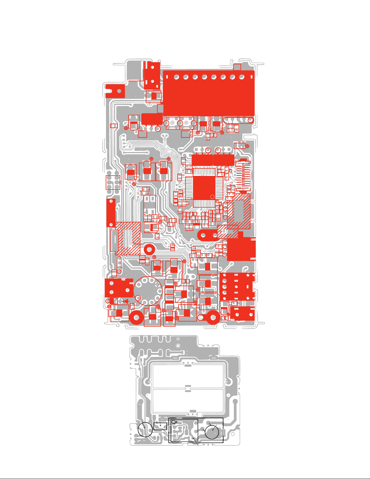
Page 24

Linear PCB
SCHEMATIC DIAGRAMS AND WAVEFORMS
TP3
4
3
TP5
5
19
TP8
6
Pad IF
TP7
BU
BV
BM
UHF
4.0V
0V
4.0V
TP2
0~25
0~2.4
TP4
9
TP6
2
7
1
3.6
1.1
1.8
3.3
1.4
1.3
1.4
28.1
1.5
3.2
0.2
3.2
3.2
2.3
3.2
3.2
1.9
3.9
3.2
1.9
3.2
1.9
3.8
1.4
10
11
TP1
27.7
11.4
3.96
–7.84
–17.98
8
18
16
17
15
14
13
12
— 23 —
Page 25

BL
— 24 —
Page 26

WAVEFORMS
520mV
63.5µs
1
Q200 Collector
63.5µs
4 IC200 Pin 18
2 IC200 Pin 23
1.0V
IC300 Pins 32,34,36
5
2.8V
63.5µs
63.5µs
3.3V
3 IC200 Pins 19,20
4V
6 IC300 Pin 26
3.6V
230mV
63.5µs
0.2V
0.17µs
2.8V
7
IC300 Pin 21
0 Q111 Base
IC700 Pin 2
C
63.5µs
8µs
125µs
IC300 Pins 4,5
8
1.6V
A
Q111 Collector
4.6V
D IC700 Pin 3
63.5µs
8µs
63.5µs
12V
4.8V
9
B
E
125µs
IC300 Pin 39
4.8V
63.5µs
IC700 Pin 1
4.8V
63.5µs
IC700 Pin 4
— 25 —
Page 27

4.8V
4.8V
4.8V
3µs
F IC700 Pin 5
I IC300 Pin 30
125µs
G IC700 Pin 6
6V
63.5µs
63.5µs
H IC700 Pin 7
— 26 —
Page 28

8-11-10, Nishi-Shinjuku
Shinjuku-ku, Tokyo 160, Japan
Telephone: 03-3347-4926
 Loading...